
Development of Bottom-Blowing Copper Smelting Technology: A Review


Faculty of Materials Metallurgy and Chemistry, Jiangxi University of Science and Technology, Ganzhou 341000, China
*
Author to whom correspondence should be addressed.
Metals 2022, 12(2), 190; https://doi.org/10.3390/met12020190
Submission received: 30 December 2021
/
Revised: 18 January 2022
/
Accepted: 19 January 2022
/
Published: 20 January 2022
(This article belongs to the Special Issue Fundamentals of Advanced Pyrometallurgy)
Abstract
:Bottom-blowing copper smelting technology was initiated and developed in China in the 1990s. Injection of oxygen-enriched high-pressure gas strongly stirs the molten bath consisting of matte and slag. Rapid reaction at relatively lower temperatures and good adaptability of the feed materials are the main advantages of this technology. Development and optimisation of bottom-blowing copper smelting technology were supported by extensive studies on the thermodynamics of the slag and the fluid dynamic of the molten bath. The history of technological development and fundamental studies related to this technology are reviewed in this paper.
1. Introduction
Smelting is one of the important processes in the pyrometallurgical production of blister copper in which copper–iron sulphides are oxidised to form molten matte and slag. Flash smelting and bath smelting are the major smelting technologies in copper production. Copper concentrates react with oxygen directly in the flash smelting process which has the advantages of high capacity and automatic control. However, fine and dry feeds are required for the flash smelting furnace to enable fast reactions. As a result, considerable feed preparation is required, and the dust rate is relatively higher. It has limited ability to treat scrap and other copper-containing materials with large sizes. Bath smelting is an alternative technology to flash smelting which involves the reactions of copper concentrate with oxygen in the molten bath. Several technologies have been developed based on the bath smelting principles that include IsaSmelt/Ausmelt, Noranda/El Teniente, Vanyukov, Mitsubishi and recently developed bottom-blowing smelting (BBS) process [1,2,3,4]. Due to its unique technological features, such as good adaptability to raw materials, high oxygen utilisation and thermal efficiency, and flexible capacity, BBS technology has attracted strong interest from the copper industry [5,6,7,8,9,10,11,12,13,14]. In 2016, 13 BBS furnaces were constructed or were under construction with the capacity of 1600 kt/a copper production. The furnace size ranged from Ø3.8 m × 11.5 m to Ø5.8 m × 30 m [5,14]. The fundamental studies including thermodynamics of the slag and fluid dynamic of the molten bath have been extensively conducted in recent years to understand and support the new technology. This review summarises the development of the copper BBS including the history, features and relevant fundamental studies.
2. History of Technology Development
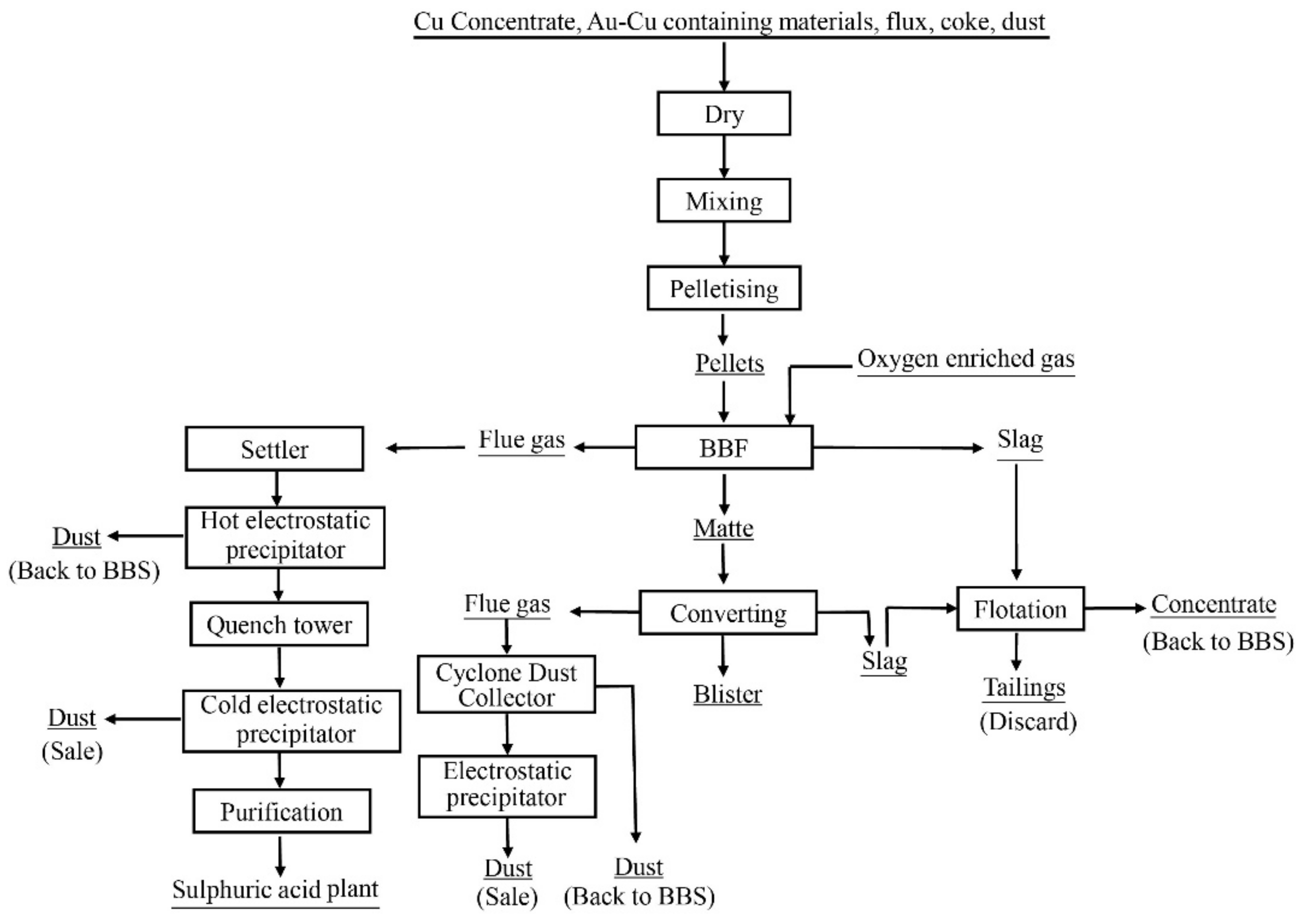
From November 1991 to June 1992, a plant trial was conducted at Shuikoushan (SKS) Smelter for a period of 217 days to smelt copper concentrate in a bottom-blowing furnace [15,16]. The name of SKS Smelting Technology was therefore used initially to represent the bottom-blowing copper smelting technology. Figure 1 below shows the flowsheet of the SKS trial [16]. It can be seen from the figure that carbon fuel was used during the trial, and the feeds were palletised during the trial. The smelting slag was treated by flotation process to recover copper and the concentrate from the flotation was sent back to the bottom-blowing furnace (BBF). Only the coarse flue dust from the BBF and PS converter was sent back to the BBF. The detailed operating parameters are given in Table 1. It can be seen from Table 1 that the BBF treated 50 t feeds per day during the trial and Cu in the concentrate was approximately 20%. Matte with 50% Cu was produced and Cu in the slag was in the range of 1–3%. Oxygen utilization at 100% was claimed and a lance life of 5000 h was estimated.
In 2005 the first industrial scope BBF was built in Sin Quyen smelter in Vietnam. The size of the furnace was Ø3.8 m × 11.5 m and the capacity was designed to be 10,000 t Cu per year [6,17]. However, the BBF in Sin Quyen smelter seemed not operating properly as no operating details were reported. In 2008 the first real commercialised BBF started in Dongying Fangyuan Nonferrous Metals (Fangyuan) [7]. The main equipment was a horizontal cylindrical furnace shown in Figure 2. The size of the furnace was Φ 4.4 m × 16.5 m and it was lined with 380 mm thick chrome-magnesia bricks. The BBF had nine gas lances arranged in two rows on the bottom, five lances at 7 degrees and four lances at 22 degrees towards the outside. Each lance consisted of an inside tube and an external shroud. The inside tube injected pure oxygen and the shroud injected airflow as a coolant to protect the lance. The furnace operated with a rotation mechanism so the lances could be rolled above the molten bath during maintenance, repair, power failure or another emergency. Mixed feed materials with 7–10 wt% moisture were continuously transported by a belt conveyor into the high-temperature melt in the furnace through a feed mouth located above the reaction zone. High-pressure oxygen and air were blown constantly by the lances into the copper matte, in which iron and sulphur were rapidly oxidised. The by-product SO2 was sent to the acid plant and the slag was tapped regularly followed by the flotation process to recover copper. Matte was tapped regularly and sent to the PS converters by a ladle.
Table 2 shows key process parameters in the Fangyuan smelting plant in January 2012 compared with the initial design. The effort made by the management and engineers enabled unexpected performance to be achieved in the first commercialised BBF. Differently from the trials in Shuikoushan, the following advantages were demonstrated in the Fangyuan BBF:
- (1).
- No carbon fuel was used—no CO2 was generated.
- (2).
- Feed preparation was not required—up to 100 mm size could be fed into the BBF directly.
- (3).
- High-grade matte with 70% Cu was produced—more concentrate could be treated.
- (4).
- Concentrate feed rate increased from 32 to 75 dry t/h—the furnace capacity was more than doubled.

Table 2.
Typical process parameters for Fangyuan smelting plant in January 2012. Data derived from [7].
Table 2.
Typical process parameters for Fangyuan smelting plant in January 2012. Data derived from [7].
| Parameter | Unit | Design | January 2012 |
|---|---|---|---|
| Maximum concentrate feed rate | dry t/h | 32 | 75 |
| Average concentrate feed rate | dry t/h | 32 | 70 |
| Average Cu content in concentrate | % | 25 | 22 |
| Average moisture of the feed | % | 8 | 7 |
| Average silica flux feed rate | dry t/h | - | 8 |
| Average coal feed rate | dry t/h | 2.46 | 0–0.8 |
| Total average feed to the furnace | wet t/h | - | 90 |
| Average copper matte grade | % | 55 | 70 |
| Average Fe/SiO2 in slag | - | 1.7 | 1.8 |
| Average Cu in smelting slag | % | 4 | 2.6 |
| Average Cu in flotation tailing slag | % | 0.42 | 0.3 |
| Average oxygen + air flow rate | Nm3/s | - | 4.2 |
| Average oxygen enrichment | % | 70 | 72 |
| Bath temperature range | °C | 1180–1200 | 1150–1170 |
Compared with other bath smelting technologies, BBF shows several advantages:
- (1).
- Less preparation of feeds
Top blowing technology (Ausmelt and Isasmelt) requires pelletised feeds and side blowing technology (Teniente Converter) needs to inject dry and fine particle feeds. BBF can treat a wide range of size feeds up to 100 mm diameter with moisture up to 10%.
- (2).
- High gas pressure and long lance life
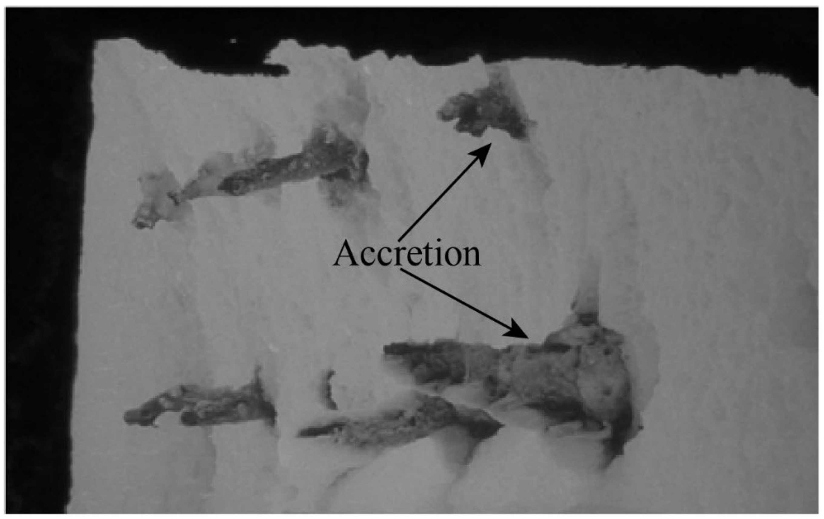
Much higher gas pressure in BBF has many advantages confirmed by Kapusta et al. [18,19,20,21,22,23]. As one of the significant developments at Fangyuan, a series of trials were undertaken to identify the optimum pressures of the oxygen and air in the lances. It was found that optimum gas pressures were related to the feeding rate, the viscosity of the slag, thicknesses of the slag and matte layers. The following requirements need to be met: (1) no backflow of matte into the lances; (2) enough stirring for rapid reactions and generation of the surface wave; (3) no strong splashing of the slag and matte to block the feed mouth and (4) a protection accretion is formed at the tip of the lance. Figure 3 shows the “mushroom” formed at the tip of the lances which enabled the lance life to be over 10 months [7]. These mushroom tips not only protect the lances but also distribute the injected gases to small bubbles.
- (3).
- Autogenous Smelting
Autogenous operation was achieved in the BBF at Fangyuan for smelting of normal copper concentrates. This operation reduced energy consumption and CO2 emission. The autogenous smelting was obtained by (1) low-temperature operation; (2) low slag rate resulting in a high Fe/SiO2 ratio; (3) low off-gas volume resulting in high oxygen concentration; (4) high thermal efficiency as most of the oxidisation reactions occur in the lower part of the bath, the heat generated from these reactions can be efficiently absorbed by the molten matte and slag.
- (4).
- Low-Temperature Smelting
The slag temperatures measured at the taphole of the Fangyuan BBF were usually in the range of 1150 to 1170 °C which was much lower than the liquidus temperature of the slag [7,24]. Approximately 20% solid spinel was present in the slag which increased the slag viscosity significantly. High-pressure gases injected from the bottom of the molten bath can generate surface waves that push the viscous slag out of the furnace through the taphole. The advantages of low-temperature smelting are (1) no extra fuels are required to maintain smelting temperature (although oil jets were available on both ends of the BBF, they were rarely used); (2) low consumption of the refractory. There was no significant erosion of the refractory on most parts of the furnace after one and a half years operation since spinel accretion was formed to protect the refractory [24,25,26,27]; (3) relatively higher viscosities of the matte and slag allowed higher pressures of the injected gases without strong splashing; (4) a higher-grade matte can be produced at a lower temperature at a given oxygen partial pressure.
3. Fundamental Studies to Support Development of BBS Technology
3.1. Slag Chemistry
In the conventional theory of pyrometallurgy, the slag temperature must be higher than its liquidus temperature to avoid the formation of the solid phase. In Fangyuan BBF operation, high matte grade and high Fe/SiO2 in the slag resulted in a high liquidus temperature of the smelting slag. In contrast, the BBF slag temperature was lower than other copper smelting technologies [7,28,29,30]. It was doubted widely that either slag composition or temperature was not reliable. Researchers from the University of Queensland measured the slag tapping temperatures carefully using a K-type thermocouple and collected quenched slag samples. In combination with electron probe X-ray microanalysis (EPMA) and thermodynamic analyses [31], it was confirmed that it is possible to operate BBF with a viscous slag containing solid phase.
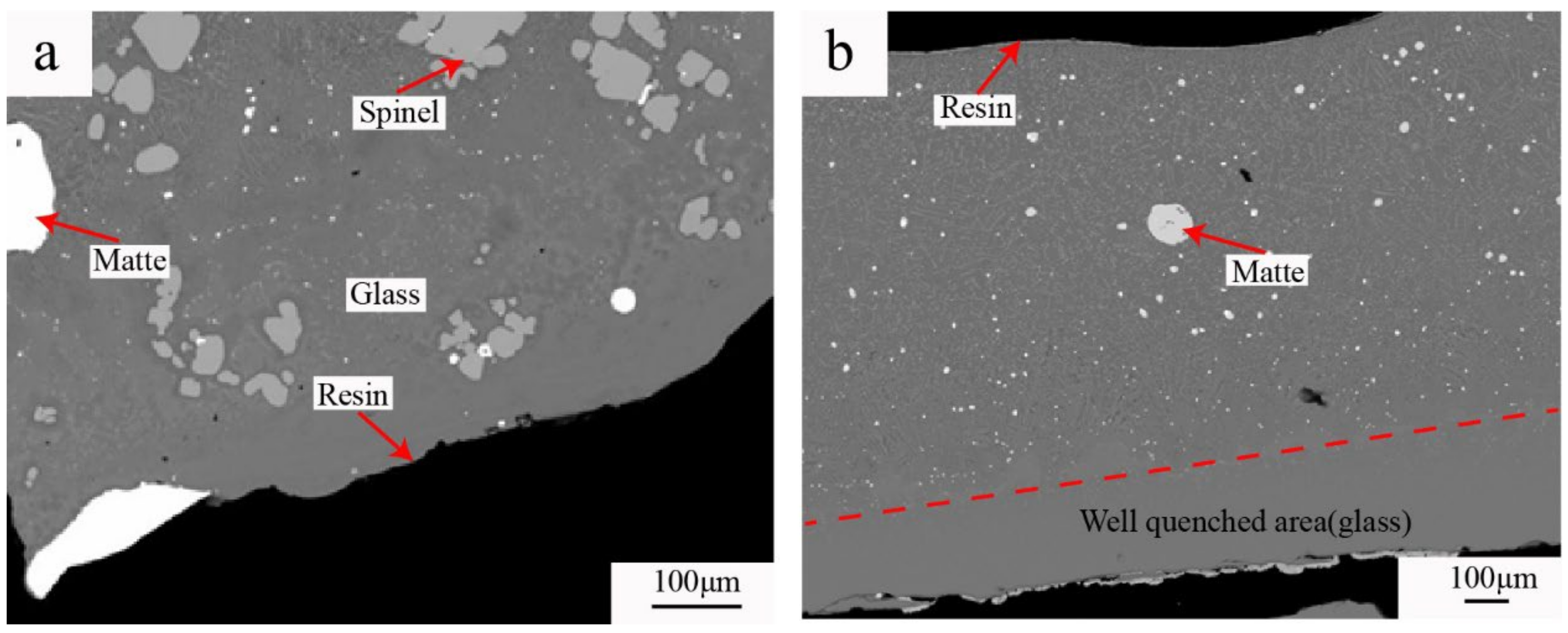
Figure 4 shows a typical microstructure of the quenched BBF slag compared with the FSF slag [7]. It can be seen from Figure 4a that liquid, spinel and matte phases were present in the slag. The shape and size of the spinel phase indicate that the spinel was the primary phase presented at high temperatures. The slag tapping temperature of the BBF was therefore lower than its liquidus temperature. The matte droplets in different sizes were also present in the slag. In contrast, it can be seen from Figure 4b that no solid phase was found in the quenched flash smelting slag. The compositions of the phases present in a quenched BBF slag were measured by EPMA and are shown in Table 3 together with the bulk composition measured by XRF. Both EPMA and XRF can only measure elemental compositions. The compositions shown in the table were calculated by assuming that the elements were present in certain forms of oxides or elements in the slag. It is estimated from the compositions that the proportion of the spinel is approximately 16.8 wt%.
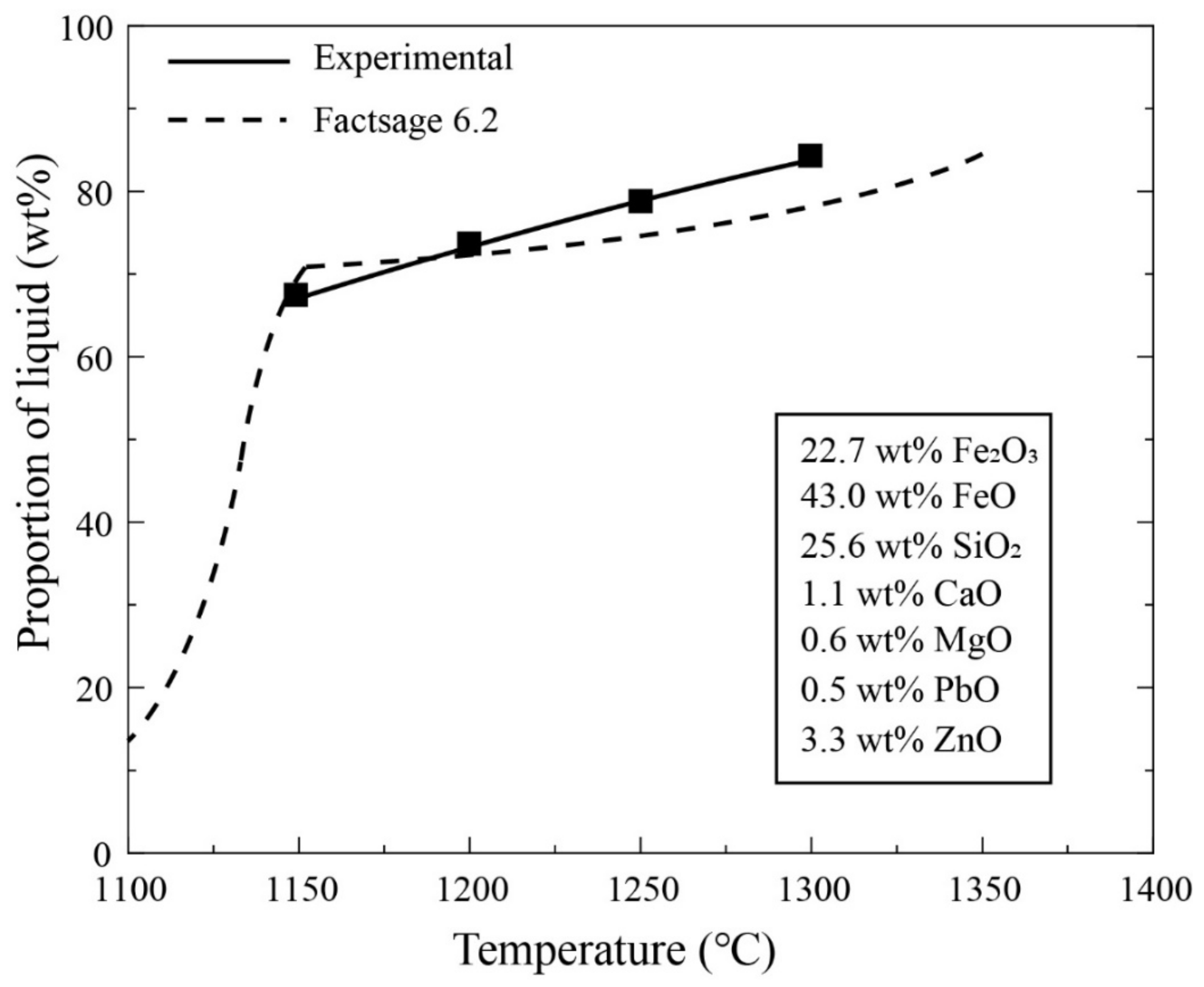
Reheating experiments were carried out using the slag shown in Table 3 under ultra-high purity Ar flow. The experiments were undertaken at 1150, 1200, 1250 and 1300 °C respectively using Pt foil. In these experiments, the oxygen partial pressure was not controlled, it was assumed that there was no oxygen exchange between the slag and Ar gas. FactSage was used to simulate the reheating experiments. The experimentally determined proportion of liquid phase from mass balance was compared with FactSage predictions. It can be seen from Figure 5 that both experimental data and FactSage predictions showed the proportion of liquid phase decreased slowly with decreasing temperature between 1150 and 1300 °C [7]. This indicates that equilibrium was obtained during the reheating experiments and the FactSage predictions were relatively reliable under the condition used. Reheating experiments were not undertaken below 1150 °C. It can be seen from the figure that, according to the FactSage predictions, the proportion of liquid phase decreases sharply if the temperature is lower than 1150 °C due to the formation of other solid phases such as olivine and silica.
3.2. Phase Equilibria
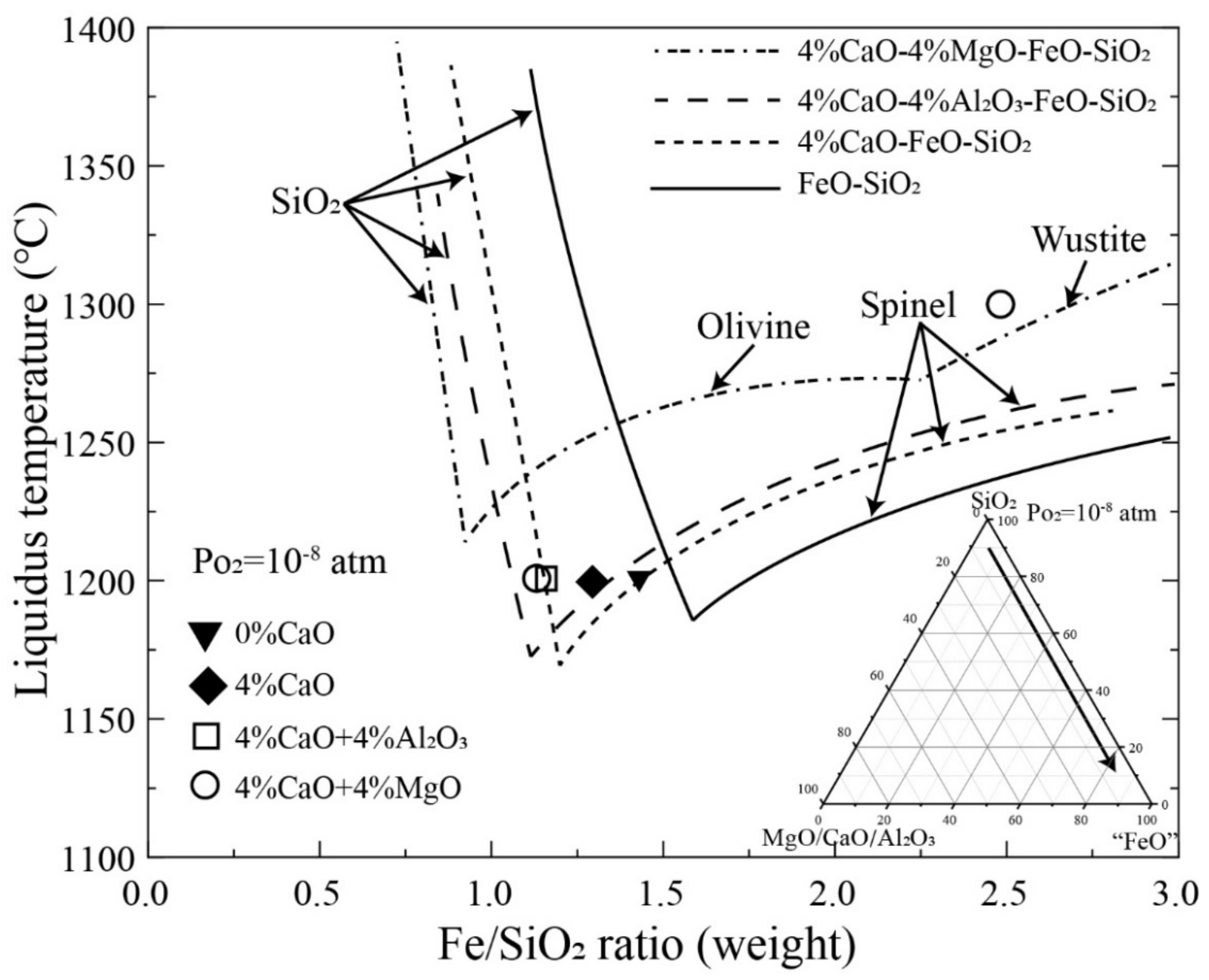
It can be seen from Table 3 that significant amounts of Al2O3, CaO, MgO and ZnO are present in the BBF slag which can influence the liquidus temperature of the slag. Systematic studies were conducted under controlled oxygen partial pressures to evaluate the effects of these components on liquidus temperature of the copper smelting slag [32,33,34,35,36,37,38,39]. Figure 6 shows liquidus temperature as a function of Fe/SiO2 weight ratio at Po2 = 10−8 atm [32]. The lines in the figure were calculated by FactSage 6.2 [31] and the symbols represent experimental data. It can be seen that spinel and tridymite are the primary phases in the composition range investigated for “FeO”–SiO2, “FeO”–SiO2–CaO and “FeO”–SiO2–CaO–Al2O3 slags. Olivine and wustite primary phase fields replaced spinel primary phase fields when 4 wt% CaO and 4 wt% MgO are present in the slag. Additions of CaO and Al2O3 move the low-liquidus region towards a low Fe/SiO2 direction and increase the liquidus temperatures in the spinel primary phase field. FactSage predictions showed similar trends on the liquidus temperature as the experimental results. However, there are significant differences in liquidus temperatures between FactSage predictions and experimental results in some areas indicating that the FactSage database needs to be improved.
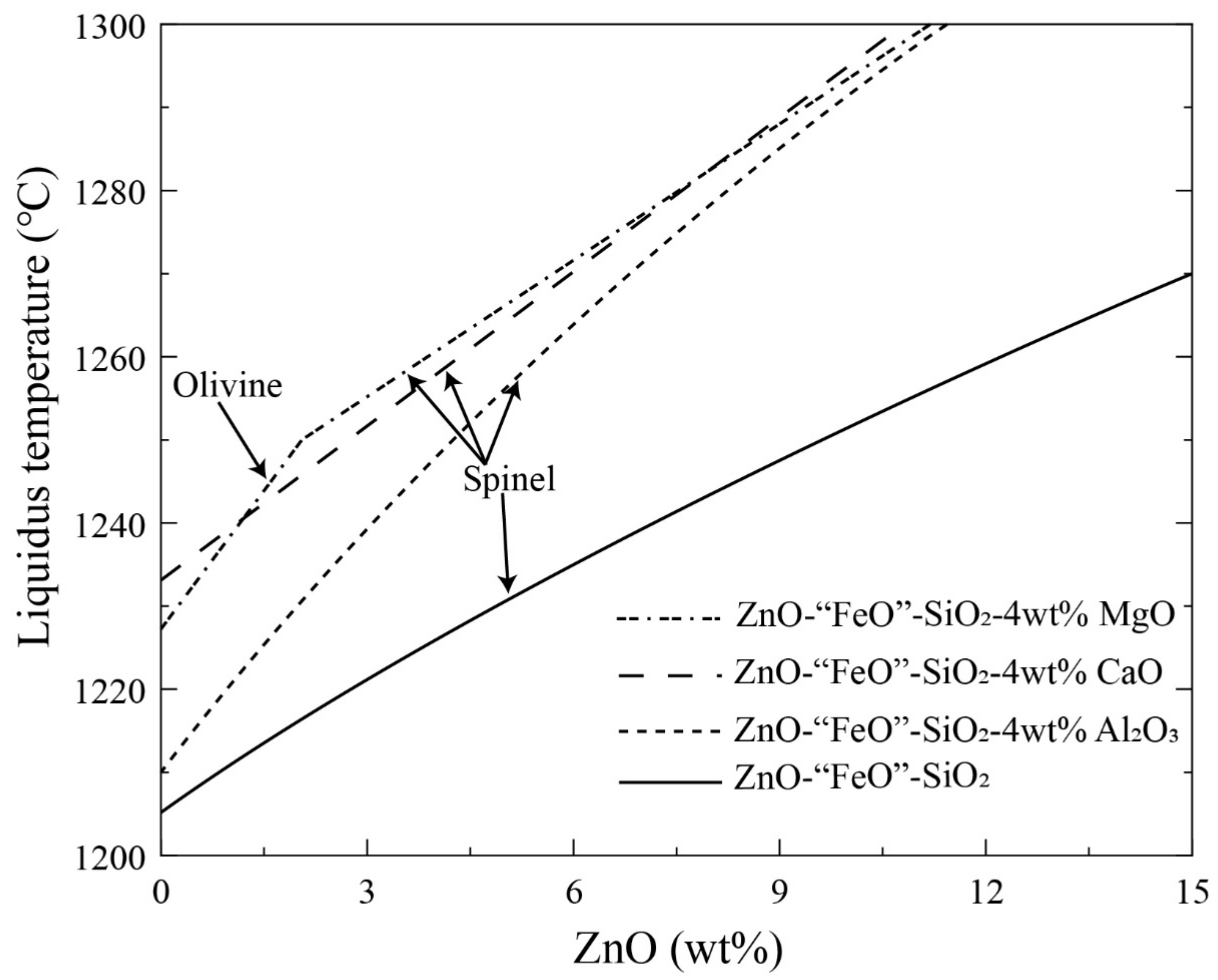
The phase equilibria in the system ZnO–“FeO”–SiO2–Al2O3–CaO–MgO were systematically studied under controlled oxygen partial pressure by Liu et al. [33,34,35,36]. Figure 7 shows the effects of ZnO, Al2O3, CaO and MgO on liquidus temperatures at fixed FeO/SiO2 = 1.9 and Po2 10−8 atm [33]. Spinel is the only primary phase at the given conditions without MgO. Olivine is the primary phase when 4 wt% MgO and less than 2 wt% ZnO are present. It can be seen from the figure that, the liquidus temperatures of the copper smelting slag always increase with increasing ZnO concentration in the slag. The introduction of 4 wt% CaO, MgO or Al2O3 into the ZnO–“FeO”–SiO2 slag significantly increases the liquidus temperature in the spinel primary phase field. It seems that the liquidus temperatures are more sensitive to the CaO and MgO concentrations than that of Al2O3.
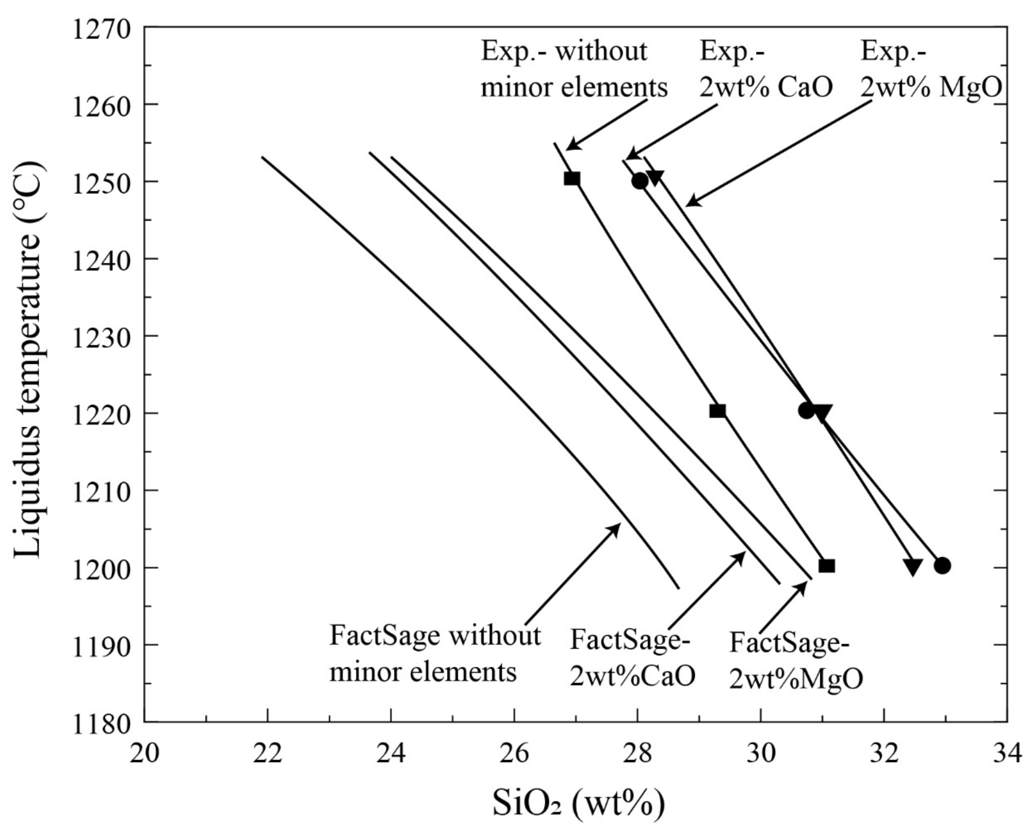
An experimental technique was further developed to determine phase equilibria of the copper smelting slags under conditions closer to the smelting process. The phase equilibria in the systems “FeO”–SiO2, “FeO”–SiO2–CaO and “FeO”–SiO2–CaO–MgO were experimentally investigated at fixed P(SO2) = 0.3 and 0.6 atm and a fixed matte grade 72 wt% Cu [37,38,39]. Figure 8 shows the effects of 2 wt% CaO or MgO on the liquidus temperatures in the spinel primary phase field at fixed P(SO2) = 0.3 atm with a fixed matte grade of 72 wt% Cu [38]. The predictions by FactSage 7.3 were also shown in the figure for comparison. It can be seen from the figure that, both the predictions and experimental results indicate that the liquidus temperatures decrease with increasing SiO2 concentration in the spinel primary phase field. The presence of 2 wt% CaO or MgO significantly increases the liquidus temperatures. To keep a constant liquidus temperature, more SiO2 flux is required which will increase the slag volume. FactSage 7.3 predicted much lower liquidus or less SiO2 flux than the experimental results as no experimental data were reported in such complex conditions for FactSage optimisation.
With increased impurities in copper concentrates, control of the minor elements is an important issue in the copper smelting process. Based on the principle of Gibbs energy minimisation and the technological features of the BBS process, a multiphase equilibrium model SKS simulation software (SKSSIM) was developed [40,41]. Distributions of As, Bi, Sb, Pb and Zn as a function of matte grade can be calculated among slag, matte and gas. The calculated distributions in the BBS process were different from that in the Isasmelt and the flash smelting processes [42,43,44].
3.3. Fluid Dynamic Studies
The major difference between BBS and other bath smelting technologies is the direction of gas injection and gas pressure. High-pressure gas injected from different directions significantly influences stirring energy, surface waves, plume eye and splashing. Fluid dynamics of the molten bath is an important issue to understand the advanced performance of the BBS. Extensive studies were conducted on the fluid dynamic behaviours of the BBF using a water model and CFD (Computational Fluid Dynamic) simulation [45,46,47,48,49,50,51,52,53,54,55,56,57,58,59,60,61,62,63,64,65,66,67,68]. Mixing behaviour [45,46,47,48,49,50,51], surface wave [52,53], plume eye [54], bubble behaviour [55,56,57,58], fluctuating behaviour [59] were studied by water model to simulate the molten bath in BBF. Lance arrangement [60,61,62], gas–liquid multi-phase flows [63,64,65], flow and mixing behaviour [66] and multiphase interface behaviours [67,68] in the BBF were studied by the CFD method. A summary of the research on the fluid dynamic of the molten bath in BBF is presented in Table 4. Some examples are given in the following sections.
In a molten bath, the first step of the reactions is the melting of the concentrate particles and decomposition of the sulphides, such as FeS2 and CuFeS2. These sulphides are then oxidised to form FeS–Cu2S matte and iron oxides (FeO, Fe2O3). The iron oxides generated by the reactions continuously react with SiO2 to form slag which is insoluble to matte and floats on the top of the matte layer. On the other hand, the injected oxygen reacts with iron, copper and sulphur on the bottom of the bath to generate all heat to maintain the temperature of the molten bath. The mass and thermal transfer inside the molten bath significantly affect the reaction efficiency of the BBF. Cai et al. [69] did experiments in a physical model of a bottom-blowing lead smelting furnace to find an optimal lance arrangement and configuration. An empiric calculation formula was concluded by normal hydraulic model test:
where S is the effective stirring diameter of the oxygen lance, W is the space between oxygen lances, D0 is the inner diameter of the export oxygen lance, Fr′ is the modified Froude number, H is the depth of bath pool, D is the inner diameter of the furnace. In a late study, Shui et al. [48] defined effective stirring range De quantitatively and developed the 1st empiric equation to characterise the mixing behaviour of the copper BBF.
S/W = 26.224∙(W/D0)−0.629∙(Fr′)0.122∙(H/D)0.523
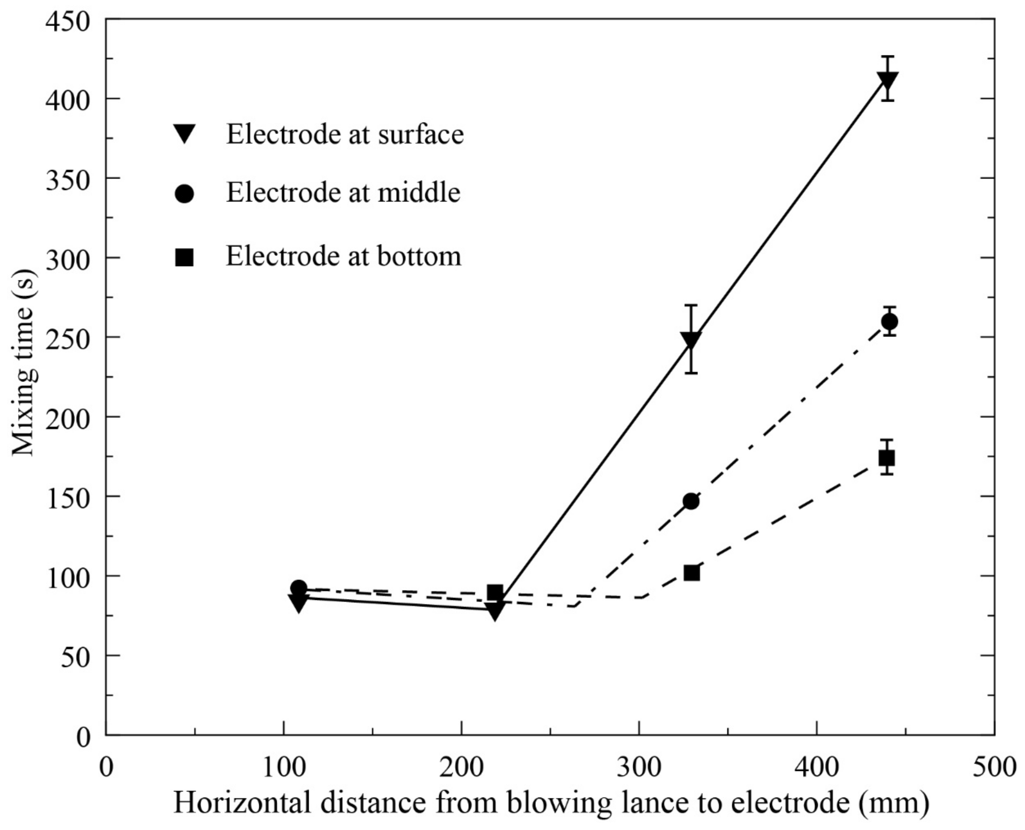
Figure 9 shows the mixing time as a function of distance from the lance at different depths of the bath [48]. In the water model experiments, 4 M KCl solution as a tracer of electric conductivity was added directly on the top of the gas injection lance. An electrode connected to a potentiostat was put in the required position to measure the electric conductivity of that location. The time to reach a stable electric conductivity was defined as “mixing time”. It can be seen that within 220 mm the mixing time on the surface decreases slightly and then increases sharply with increasing the distance between the lance and electrode. However, De is different at different depths of the bath and increases with increasing the depth. When the horizontal distance from the lance is greater than De, the mixing time increases rapidly with increasing the distance. The maximum distance between two neighbour lances is the De on the surface to ensure the whole bath in the reaction zone can be efficiently stirred.
The empiric equation to characterise the mixing behaviour of the copper BBF was obtained from the experimental measurements of the water model [48]
where τ is mixing time, Q is gas flow rate and h is bath height. Several important findings from this study can be directly applied to BBS:
- The effective stirring range can be accurately determined for a single lance which is one of the important parameters to design the number of lances and distance between the lances. The optimum number and distance of the lances enable the bath to be efficiently mixed with minimum energy and gas consumption.
- Within the effective stirring range, the mixing time is not sensitive to the vertical locations. However, the effective stirring range is smaller on the surface and mixing energy decreases much faster at the surface beyond the range. In copper BBF, many reactions occur on the surface of the bath as all solid materials are fed from the top. It is therefore important to ensure the surface area in the reaction zone is fully covered within the effective stirring area by proper arrangement of the lances.
- Equation (2) is the first quantitative expression of the mixing time for copper BBF. Required injection gas flow rate and bath height can be calculated from this equation according to productivity.
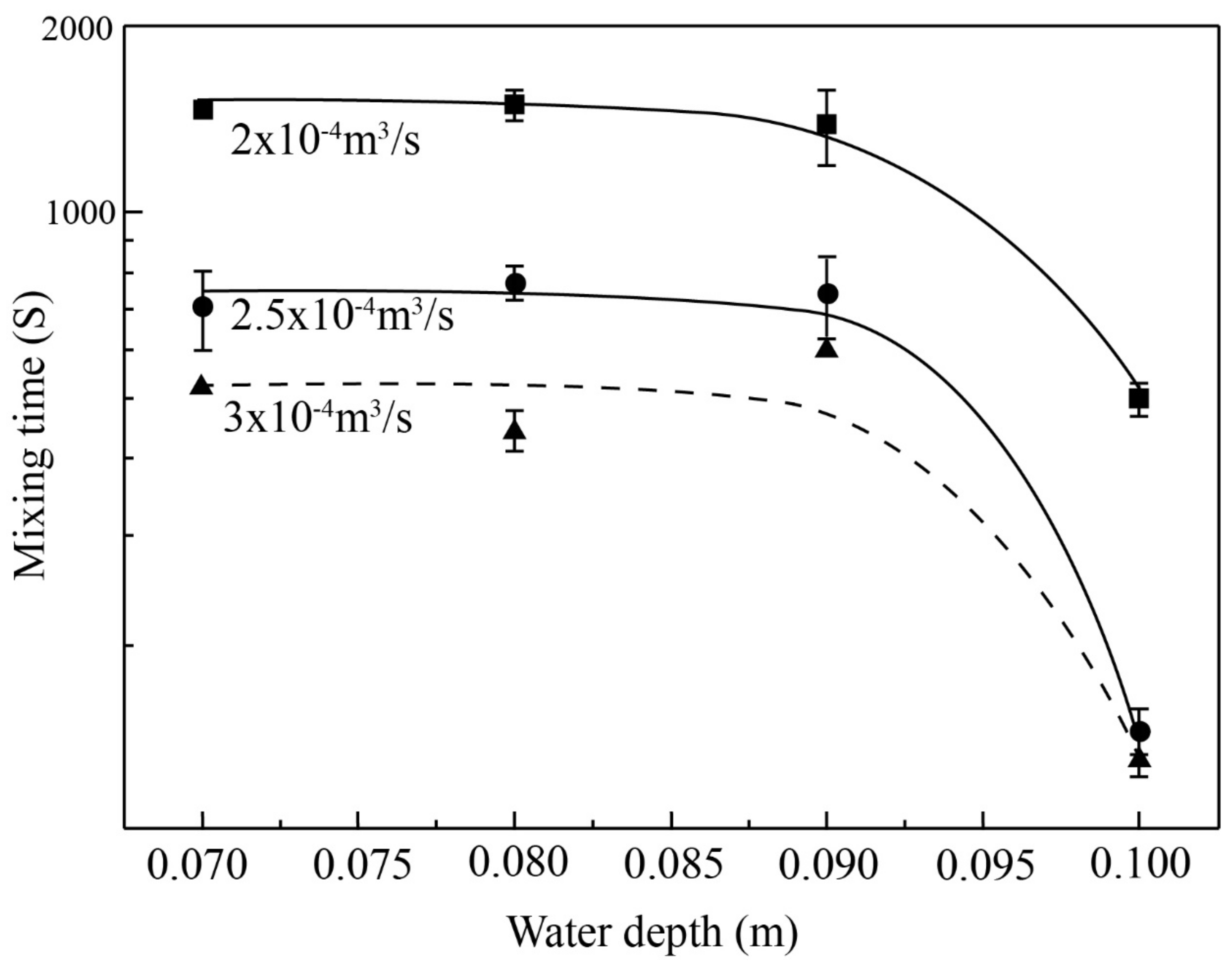
In copper BBF operation, molten matte is covered by a thick slag layer. The fluid dynamic studies for a single layer bath are not enough to accurately describe the molten bath of the copper BBF. Jiang et al. [50] and Shui et al. [49] studied mixing behaviours of two-layer baths by using silicon oil and water to simulate slag and matte, respectively. It can be seen from Figure 10 that the changes in mixing time are not significant when the water thickness increases from 0.07 m to 0.09 m, but there is a sharp decrease when the water thickness exceeds 0.09 m. This indicates that a minimum matte height is required to generate enough stirring energy to mix the bath efficiently. In addition, it can be seen that the trends are similar at different gas flow rates.
An empiric equation was also generated for a two-layer bath in copper BBF [49]. Four variables H, Q, h, νs were converted into SI units and correlated with the experimental mixing time in an overall multiple regression:
where τ is mixing time, Q is gas flow rate, H is water height, h is oil height and is oil viscosity.
The waves formed on the bath surface play important role in the BBF operations. Tapping of the viscous slag, corrosion of the refractory around the surface and settlement of the matte droplets in the slag are all associated with the bath waves. Simulation experiments were carried out to investigate the features of the waves formed on the bath surface of the BBF [52,53]. It was found that the ripples, the 1st asymmetric standing wave and the 1st symmetric standing wave can occur in the BBF bath. Empirical occurrence boundaries were determined from water model experiments. The amplitude of the 1st asymmetric standing wave was found to be much greater than the 1st symmetric standing wave and the ripples. The amplitudes increase with increasing bath height and flow rate but decrease with blowing angle. The frequency of the 1st asymmetric standing wave was found to increase with increasing bath height but be independent of gas flowrate and blowing angle. The dimensionless number can be expressed as
where ρL is liquid density (kg/m3), is the surface tension of the liquid (dyn/cm), D is container inner diameter (mm), Qg is gas flowrate (mL/s).
Figure 11 shows the conditions for the occurrence of the 1st asymmetric standing waves [53]. The solid curves show the correlated boundaries while the points show the experimental results. It can be seen that, in general, the boundaries of different blowing angles are similar in shape. On the right side of the boundary, the 1st asymmetric standing wave is present, while on the left side only minor ripples occur.
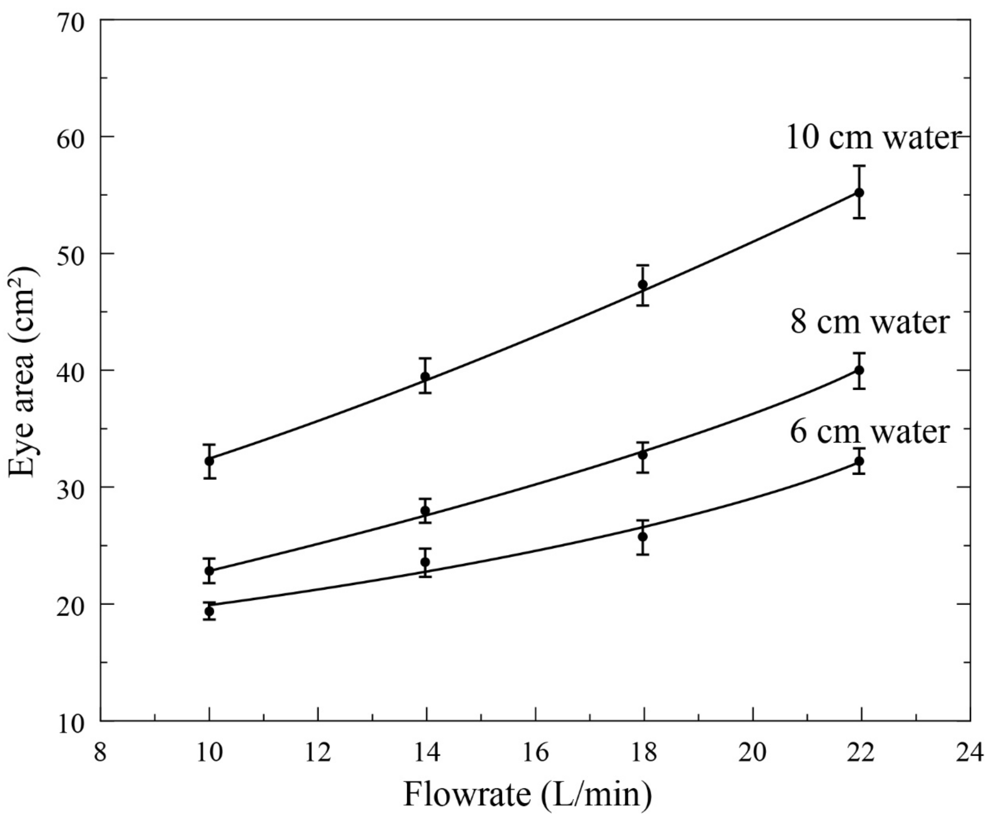
During the Fangyuan BBF operation, it was observed from the feeding mouth that a plume eye was formed on the surface of the bath. The plume eye was initially observed and reported in the steelmaking process to describe the exposure of the lower liquid as the upper-level liquid was pushed away by the bottom injected gas. Through the water model experiments, it was found that the sizes of the plume eyes increase with increasing gas flow rate and lower liquid thickness, decrease with increasing upper liquid thickness [54]. Figure 12 shows the effects of gas flow rate and water height on the plume eye area at a fixed oil thickness.
A modified model was developed in this study from the experimental data to predict the size of the plume eye [54]. Formation of the plume eye is important to understand the rapid reaction of the BBF. The presence of a plume eye below the feeding mouth means that the dropped copper concentrate (considered as low-grade matte) can enter and melt rapidly inside the matte layer where the oxygen partial pressure is relatively high. The formed iron and sulphur oxides in the matte raise to the slag layer.
4. Conclusions
Commercialised bottom-blowing copper smelting technology started in 2008. In less than 15 years this new technology has been developed rapidly to be the second-largest copper smelting technology. Development history and features of the new technology were reviewed from extensive publications. It is demonstrated that fundamental studies on slag chemistry and bath fluid dynamics have played an important role in supporting the development of this new technology. High-pressure gas injected from the bottom of the molten bath showed several advantages: (1.) generating a plume eye to allow the copper concentrate to react with matte directly; (2.) the surface waves assist in the tapping of the viscus slag so that low-temperature operation to produce high-grade matte with high Fe/SiO2 slag is possible; (3.) strong stirring energy to enable fast reactions in the molten bath resulting in high capacity and low-copper in the slag; (4.) high efficiency of oxygen utilization and heat absorption. The flexibility of the BBS on feeding materials and productivity is expected to not only increase its application in the copper industry to treat more complicated concentrates but also to enable the exploration of more applications of this technique in other high-temperature processes.
Author Contributions
Conceptualization, B.Z.; resources, B.Z.; data curation, B.Z. and J.L.; writing—original draft preparation, B.Z.; writing—review and editing, B.Z.; All authors have read and agreed to the published version of the manuscript.
Funding
This research received no external funding.
Data Availability Statement
Not applicable.
Conflicts of Interest
The authors declare no conflict of interest.
References
- Schlesinger, M.; Sole, K.; Davenport, W.; Alvear, G. Chapter 5—Theory to practice: Pyrometallurgical industrial processes. In Extractive Metallurgy of Copper, 6th ed.; Elsevier: Oxford, UK, 2021; pp. 95–117. ISBN 9780128218754. [Google Scholar]
- Gonzales, T.W.; Walters, G.; White, M. Comparison of Smelting Technologies. In Proceedings of the 58th Annual Conference of Metallurgists (COM) Hosting the 10th International Copper Conference 2019, Vancouver, BC, Canada, 18–21 August 2019; p. 602421. [Google Scholar]
- Wang, J. Copper smelting: 2019 world copper smelting data. In Proceedings of the 58th Annual Conference of Metallurgists (COM) Hosting the 10th International Copper Conference 2019, Vancouver, BC, Canada, 18–21 August 2019; p. 592732. [Google Scholar]
- Watt, J.; Kapusta, J.P.T. The 2019 copper smelting survey. In Proceedings of the 58th Annual Conference of Metallurgists (COM) Hosting the 10th International Copper Conference 2019, Vancouver, BC, Canada, 18–21 August 2019; p. 595947. [Google Scholar]
- Cheng, L.; Wang, Z.; Jiang, J.; Huang, Q. The SKS copper smelting process in China. In Volume VI-Smelting, Technology Development, Process Modelling and Fundamentals, Proceedings of Copper 99-Cobre International Conference, Phoenix, AZ, USA, 10–13 October 1999; Diaz, C., Landolt, C., Utigard, T., Eds.; The Minerals, Metals, and Materials Society: Warrendale, PA, USA; pp. 83–91. ISBN 0873394356.
- Liang, S. A review of oxygen bottom blowing process for copper smelting and converting. In Proceedings of the 9th International Copper Conference (Copper 2016), Kobe, Japan, 13–16 November 2016; pp. 1008–1014. [Google Scholar]
- Zhao, B.; Cui, Z.; Wang, Z. A new copper smelting technology—Bottom blown oxygen furnace developed at Dongying Fangyuan Nonferrous Metals. In Proceedings of the 4th International Symposium on High-Temperature Metallurgical Processing, San Antonio, TX, USA, 3–7 March 2013; pp. 3–10. [Google Scholar]
- Cui, Z.; Shen, B.; Wang, Z.; Li, W.; Bian, R. New process of copper smelting with oxygen enriched bottom blowing technology. Nonferr. Met. Extr. Metall. 2010, 3, 17–20. (In Chinese) [Google Scholar]
- Chen, Z. The application of oxygen bottom-blown bath smelting of copper. China Nonferr. Metall. 2009, 5, 16–22. (In Chinese) [Google Scholar]
- Qu, S.; Li, T.; Dong, Z.; Luan, H. Plant practice of and design discussion on oxygen enriched bottom blowing smelting. Nonferr. Met. Extr. Metall. 2012, 3, 10–13. (In Chinese) [Google Scholar] [CrossRef]
- Du, X.; Zhao, G.; Wang, H. Industrial application of oxygen bottom-blowing copper smelting technology. China Nonferr. Metall. 2018, 4, 4–6. (In Chinese) [Google Scholar] [CrossRef]
- Wang, H.; Yuan, J.; He, R.; Wang, X. Plant practice of copper oxygen enrichment bottom blowing smelting. Nonferr. Met. Extr. Metall. 2013, 10, 15–19. (In Chinese) [Google Scholar]
- Su, G.L. Discussion on practice of “blowing oxygen at the end of the catch matte” smelting. China Nonferr. Metall. 2010, 4, 5–8. (In Chinese) [Google Scholar]
- Yan, J. Recent operation of the oxygen bottom-blowing copper smelting and continuous copper converting technologies. In Proceedings of the 9th International Copper Conference (Copper 2016), Kobe, Japan, 13–16 November 2016; pp. 13–16. [Google Scholar]
- He, S.; Li, D. Discussion on issues related to Shuikoushan Copper Smelting process. China Nonferr. Metall. 2005, 34, 19–22. (In Chinese) [Google Scholar]
- He, S.; Li, D. SKS copper smelting process. China Nonferr. Metall. 2006, 35, 6–9. (In Chinese) [Google Scholar]
- Liang, S.; Chen, Z. Application and development of oxygen enriched bottom-blowing copper smelting technology furnace. Energy Sav. Nonferr. Metall. 2013, 4, 16–19. (In Chinese) [Google Scholar]
- Kapusta, J.P.T. Implementation of air liquid shrouded injector (ALSI) technology at the Thai copper industries smelter. In 2007 International Copper Conference: The Carlos Diaz Symposium On Pyrometallurgy, Toronto, ON, Canada, 25–30 August 2007; Warner, A.E.M., Newman, C.J., Vahed, A., George, D.B., Mackey, P.J., Warczok, A., Eds.; Canadian Institute of Mining, Metallurgy and Petroleum: Montreal, QC, Canada, 2007; Volume 3, pp. 483–500. ISBN 1-894475-73-9. [Google Scholar]
- Kapusta, J.P.T.; Larouche, F.; Palumbo, E. Adoption of high oxygen bottom blowing in copper matte smelting: Why is it taking so long? In Proceedings of the Torstein Utigard Memorial Symposium, Toronto, Canada, 23–26 August 2015; The Materials and Metallurgical Society of CIM: Montreal, QC, Canada, 2015; pp. 1–25. [Google Scholar]
- Kapusta, J.P.T. Submerged gas jet penetration: A study of bubbling versus jetting and side versus bottom blowing in copper bath smelting. JOM 2017, 69, 970–979. [Google Scholar] [CrossRef]
- Coursol, P.; Mackey, P.J.; Kapusta, J.P.T.; Cardona Valencia, N. Energy consumption in copper smelting: A new Asian horse in the race. JOM 2015, 67, 1066–1074. [Google Scholar] [CrossRef]
- Kapusta, J.P.T. Gas jet penetration, smelting intensity, and oxygen efficiency in side blowing versus bottom blowing. In Proceedings of the 9th International Copper Conference (Copper 2016), Kobe, Japan, 13–16 November 2016; pp. 1282–1305. [Google Scholar]
- Kapusta, J.P.T.; Lee, R.G.H. The Savard-Lee shrouded injector: A review of its adoption and adaptation from ferrous to non-ferrous pyrometallurgy. In Proceedings of the 6th International Copper Conference (Copper 2013), Santiago, Chile, 1–4 October 2013; pp. 1115–1151. [Google Scholar]
- Chen, M.; Cui, Z.; Wei, C.; Zhao, B. Degradation mechanisms of refractories in a bottom blown copper smelting furnace. In Proceedings of the 9th International Symposium on High-Temperature Metallurgical Processing, Phoenix, AZ, USA, 11–15 March 2018; pp. 149–157. [Google Scholar]
- Chen, M.; Jiang, Y.; Cui, Z.; Wei, C.; Zhao, B. Chemical degradation mechanisms of magnesia–chromite refractories in the copper smelting furnace. JOM 2018, 70, 2443–2448. [Google Scholar] [CrossRef]
- Chen, M.; Zhao, B. Investigation of the accretions in the bottom blown copper smelting furnace. In Proceedings of the 9th International Copper Conference (Copper 2016), Kobe, Japan, 13–16 November 2016; pp. 1184–1194. [Google Scholar]
- Xu, L.; Chen, M.; Wang, N.; Gao, S. Chemical wear mechanism of magnesia-chromite refractory for an oxygen bottom-blown copper-smelting furnace: A post-mortem analysis. Ceram. Int. 2021, 47, 2908–2915. [Google Scholar] [CrossRef]
- Chen, M.; Cui, Z.; Zhao, B. Slag Chemistry of Bottom Blown Copper Smelting Furnace at Dongying Fangyuan. In Proceedings of the 6th International Symposium on High-Temperature Metallurgical Processing, Orlando, FL, USA, 15–19 March 2015; pp. 257–264. [Google Scholar]
- Cui, Z.; Wang, Z.; Zhao, B. Features of the bottom blown oxygen copper smelting technology. In Proceedings of the 4th International Symposium on High-Temperature Metallurgical Processing, San Antonio, TX, USA, 3–7 March 2013; pp. 351–360. [Google Scholar]
- Chen, M.; Zhao, B. Comparison of slag chemistry between Teniente converter and flash smelting furnace. In Proceedings of the 9th International Copper Conference (Copper 2016), Kobe, Japan, 13–16 November 2016; pp. 967–975. [Google Scholar]
- Bale, C.W.; Bélisle, E.; Chartrand, P.; Decterov, S.A.; Eriksson, G.; Gheribi, A.E.; Hack, K.; Jung, I.H.; Kang, Y.B.; Melançon, J.; et al. Reprint of: FactSage thermochemical software and databases, 2010–2016. Calphad 2016, 55, 1–19. [Google Scholar] [CrossRef]
- Zhao, B.; Hayes, P.C.; Jak, E. Effects of CaO, Al2O3 and MgO on liquidus temperatures of copper smelting and converting slags under controlled oxygen partial pressures. J. Min. Metall. Sect. B Metall. 2013, 49, 153–159. [Google Scholar] [CrossRef]
- Liu, H.; Cui, Z.; Chen, M.; Zhao, B. Phase equilibria in the ZnO-“FeO”-SiO2-CaO system at Po2 10−8 atm. Calphad 2018, 61, 211–218. [Google Scholar] [CrossRef]
- Liu, H.; Cui, Z.; Chen, M.; Zhao, B. Phase equilibria study of the ZnO-“FeO”-SiO2-Al2O3 system at Po2 10−8 atm. Metall. Mater. Trans. B 2016, 47, 1113–1123. [Google Scholar] [CrossRef]
- Liu, H.; Cui, Z.; Chen, M.; Zhao, B. Phase equilibria study of the ZnO-‘FeO’-SiO2-MgO system at Po2 10−8 atm. Miner. Process. Extr. Metall. 2018, 127, 242–249. [Google Scholar] [CrossRef]
- Liu, H.; Cui, Z.; Chen, M.; Zhao, B. Phase equilibrium study of ZnO-“FeO”-SiO2 system at fixed Po2 10−8 atm. Metall. Mater. Trans. B 2015, 47, 164–173. [Google Scholar] [CrossRef]
- Chen, M.; Sun, Y.; Balladares, E.; Pizarro, C.; Zhao, B. Experimental studies of liquid/spinel/matte/gas equilibria in the Si-Fe-O-Cu-S system at controlled P(SO2) 0.3 and 0.6 atm. Calphad 2019, 66, 101642. [Google Scholar] [CrossRef]
- Sun, Y.; Chen, M.; Balladares, E.; Pizarro, C.; Contreras, L.; Zhao, B. Effect of MgO on the liquid/spinel/matte/gas equilibria in the Si–Fe–Mg–O–Cu–S system at controlled P(SO2) 0.3 and 0.6 atm. Calphad 2020, 70, 101803. [Google Scholar] [CrossRef]
- Sun, Y.; Chen, M.; Balladares, E.; Pizarro, C.; Contreras, L.; Zhao, B. Effect of CaO on the liquid/spinel/matte/gas equilibria in the Si–Fe–O–Cu–S system at controlled P(SO2) 0.3 and 0.6 atm. Calphad 2020, 69, 101751. [Google Scholar] [CrossRef]
- Guo, X.; Wang, S.; Wang, Q.; Tian, Q. Development and application of oxygen bottom blowing copper smelting simulation software SKSSIM. Nonferr. Met. Sci. Eng. 2017, 27, 946–953. [Google Scholar] [CrossRef]
- Wang, Q.; Guo, X.; Tian, Q.; Jiang, T.; Chen, M.; Zhao, B. Development and application of SKSSIM simulation software for the oxygen bottom blown copper smelting process. Metals 2017, 7, 431. [Google Scholar] [CrossRef] [Green Version]
- Wang, Q.; Guo, X.; Tian, Q.; Chen, M.; Zhao, B. Reaction mechanism and distribution behavior of arsenic in the bottom blown copper smelting process. Metals 2017, 7, 302. [Google Scholar] [CrossRef] [Green Version]
- Wang, Q.; Guo, X.; Tian, Q.; Jiang, T.; Chen, M.; Zhao, B.J. Effects of matte grade on the distribution of minor elements (Pb, Zn, As, Sb, and Bi) in the bottom blown copper smelting process. Metals 2017, 7, 502. [Google Scholar] [CrossRef] [Green Version]
- Wang, Q.; Wang, Q.; Tian, Q.; Guo, X. Simulation study and industrial application of enhanced arsenic removal by regulating the proportion of concentrates in the SKS copper smelting process. Processes 2020, 8, 385. [Google Scholar] [CrossRef] [Green Version]
- Song, K.; Jokilaakso, A. Transport phenomena in copper bath smelting and converting processes–A review of experimental and modeling studies. Miner. Process. Extr. Metall. Rev. 2020, 42, 107–121. [Google Scholar] [CrossRef]
- Wang, D.; Liu, Y.; Zhang, Z.; Shao, P.; Zhang, T. Experimental study of bottom blown oxygen copper smelting process for water model. AIP Conf. Proc. 2013, 1542, 1304–1307. [Google Scholar] [CrossRef]
- Wang, D.; Liu, Y.; Zhang, Z.; Zhang, T.; Li, X. PIV measurements on physical models of bottom blown oxygen copper smelting furnace. Can. Metall. Q. 2017, 56, 221–231. [Google Scholar] [CrossRef]
- Shui, L.; Cui, Z.; Ma, X.; Rhamdhani, M.; Nguyen, A.; Zhao, B. Mixing phenomena in a bottom blown copper smelter: A water model study. Metall. Mater. Trans. B 2015, 46, 1218–1225. [Google Scholar] [CrossRef]
- Shui, L.; Cui, Z.; Ma, X.; Jiang, X.; Chen, M.; Xiang, Y.; Zhao, B. A Water model study on mixing behavior of the two-layered bath in bottom blown copper smelting furnace. JOM 2018, 70, 2065–2070. [Google Scholar] [CrossRef]
- Jiang, X.; Cui, Z.; Chen, M.; Zhao, B. Mixing behaviors in the horizontal bath smelting furnaces. Metall. Mater. Trans. B 2018, 50, 173–180. [Google Scholar] [CrossRef]
- Ma, X.; Cui, Z.; Contreras, L.; Jiang, X.; Chen, M.; Zhao, B. Fluid dynamics studies of bottom-blown and side-blown copper smelting furnaces. In Proceedings of the 58th Annual Conference of Metallurgists (COM) Hosting the 10th International Copper Conference 2019, Vancouver, BC, Canada, 18–21 August 2019; pp. 1–8. [Google Scholar]
- Shui, L.; Ma, X.; Cui, Z.; Zhao, B. An investigation of the behavior of the surficial longitudinal wave in a bottom-blown copper smelting furnace. JOM 2018, 70, 2119–2127. [Google Scholar] [CrossRef]
- Shui, L.; Cui, Z.; Ma, X.; Rhamdhani, M.A.; Nguyen, A.V.; Zhao, B. Understanding of bath surface wave in bottom blown copper smelting furnace. Metall. Mater. Trans. B 2015, 47, 135–144. [Google Scholar] [CrossRef]
- Jiang, X.; Cui, Z.; Chen, M.; Zhao, B. Study of Plume eye in the copper bottom blown smelting furnace. Metall. Mater. Trans. B 2019, 50, 782–789. [Google Scholar] [CrossRef]
- Wang, D.; Liu, T.; Liu, Y.; Zhu, F. Water model study of bubble behavior in matter smelting process with oxygen bottom blowing. J. Northeast. Univ. Nat. Sci. 2013, 34, 1755–1758. [Google Scholar]
- Wang, D.; Liu, Y.; Zhang, Z.; Shao, P.; Zhang, T. Dimensional analysis of average diameter of bubbles for bottom blown oxygen copper furnace. Math. Probl. Eng. 2016, 2016, 4170371. [Google Scholar] [CrossRef]
- Cheng, X.; Cui, Z.; Contreras, L.; Chen, M.; Nguyen, A.; Zhao, B. Introduction of matte droplets in copper smelting slag. In Proceedings of the 8th International Symposium on High-Temperature Metallurgical Processing, San Diego, CA, USA, 26 February–2 March 2017; pp. 385–394. [Google Scholar]
- Cheng, X.; Cui, Z.; Contreras, L.; Chen, M.; Nguyen, A.; Zhao, B. Matte entrainment by SO2 bubbles in copper smelting Slag. JOM 2019, 71, 1897–1903. [Google Scholar] [CrossRef]
- Luo, Q.; Yan, H.; Jin, J.; Huang, Z.; Gong, H.; Liu, L. Gold model experiment on fluctuation behavior of liquid level in setting zone of bottom-blowing furnace. Nonferr. Met. Eng. 2020, 10, 46–53. [Google Scholar] [CrossRef]
- Yan, H.; Liu, F.; Zhang, Z.; Gao, Q.; Liu, L.; Cui, Z.; Shen, D. Influence of lance arrangement on bottom-blowing bath smelting process. Chin. J. Nonferr. Met. 2012, 22, 2393–2400. [Google Scholar] [CrossRef]
- Zhang, Z.; Yan, H.; Liu, F.; Wang, J. Optimization analysis of lance structure parameters in oxygen enriched bottom-blown furnace. Chin. J. Nonferr. Met. 2013, 23, 1471–1478. [Google Scholar] [CrossRef]
- Guo, X.; Yan, S.; Wang, Q.; Tian, Q. Layout optimization of oxygen lances of oxygen bottom blown furnace. Chin. J. Nonferr. Met. 2018, 28, 2450–2550. [Google Scholar] [CrossRef]
- Zhang, Z.; Chen, Z.; Yan, H.; Liu, F.; Liu, L.; Cui, Z.; Shen, D. Numerical simulation of gas-liquid multi-phase flows in oxygen enriched bottom-blown furnace. Chin. J. Nonferr. Met. 2012, 22, 1826–1834. [Google Scholar] [CrossRef]
- Tang, G.; Silaen, A.K.; Yan, H.; Cui, Z.; Wang, Z.; Wang, H.; Tang, K.; Zhou, P.; Zhou, C. CFD study of gas-liquid phase interaction inside a submerged lance smelting furnace for copper smelting. In Proceedings of the 8th International Symposium on High-Temperature Metallurgical Processing, San Diego, CA, USA, 26 February–2 March 2017; pp. 101–111. [Google Scholar]
- Li, D.; Dong, Z.D.; Xin, Y.; Cheng, L.; Guo, T.; Li, B.; Li, P. Research of gas–liquid multiphase flow in oxygen-enriched bottom blowing copper smelting furnace. In Proceedings of the 11th International Symposium on High-Temperature Metallurgical Processing, San Diego, CA, USA, 23–27 February 2020; pp. 975–986. [Google Scholar]
- Shao, P.; Jiang, L. Flow and mixing behavior in a new bottom blown copper smelting furnace. Int. J. Mol. Sci. 2019, 20, 5757. [Google Scholar] [CrossRef] [Green Version]
- Guo, X.; Wang, Q.; Tian, Q.; Zhang, Y. Mechanism and multiphase interface behavior of copper sulfide concentrate smelting in oxygen-enriched bottom blowing furnace. Nonferr. Met. Sci. Eng. 2014, 5, 28–34. [Google Scholar] [CrossRef]
- Guo, X.; Wang, Q.; Tian, Q.; Zhao, B. Performance analysis and optimization of oxygen bottom blowing copper smelting process. Chin. J. Nonferr. Met. 2016, 26, 689–698. [Google Scholar] [CrossRef]
- Cai, C.; Liang, Y.; Qian, Z. A model study on the continuous leadmaking process with bottom oxygen injection. Chin. J. Process. Eng. 1985, 4, 113–121. (In Chinese) [Google Scholar]
Figure 1.
Flowsheet of SKS copper smelting technology, adapted from [16].
Figure 1.
Flowsheet of SKS copper smelting technology, adapted from [16].

Figure 2.
The bottom-blowing furnace at Dongying Fangyuan Nonferrous Metals. Reprinted with permission from ref. [7]. Copyright 2021 John Wiley and Sons.
Figure 2.
The bottom-blowing furnace at Dongying Fangyuan Nonferrous Metals. Reprinted with permission from ref. [7]. Copyright 2021 John Wiley and Sons.

Figure 3.
“Mushroom” tips formed on the lances of the Fangyuan BBF. Reprinted with permission from ref. [7]. Copyright 2021 John Wiley and Sons.
Figure 3.
“Mushroom” tips formed on the lances of the Fangyuan BBF. Reprinted with permission from ref. [7]. Copyright 2021 John Wiley and Sons.

Figure 4.
Typical microstructures of quenched smelting slag from Fangyuan BBF (a) (Reprinted with permission from ref. [7]. Copyright 2021 John Wiley and Sons) and a flash furnace (b).
Figure 4.
Typical microstructures of quenched smelting slag from Fangyuan BBF (a) (Reprinted with permission from ref. [7]. Copyright 2021 John Wiley and Sons) and a flash furnace (b).

Figure 5.
Proportion of liquid as a function of temperature for a typical BBF slag, in comparison between experimental results and FactSage 6.2 predictions. Reprinted with permission from ref. [7]. Copyright 2021 John Wiley and Sons.
Figure 5.
Proportion of liquid as a function of temperature for a typical BBF slag, in comparison between experimental results and FactSage 6.2 predictions. Reprinted with permission from ref. [7]. Copyright 2021 John Wiley and Sons.

Figure 6.
Liquidus temperature as a function of Fe/SiO2 weight ratio, Po2 = 10−8 atm, lines were calculated by FactSage 6.2, symbols are experimental results in spinel (1200 °C) and wustite (1300 °C) primary phase fields [32].
Figure 6.
Liquidus temperature as a function of Fe/SiO2 weight ratio, Po2 = 10−8 atm, lines were calculated by FactSage 6.2, symbols are experimental results in spinel (1200 °C) and wustite (1300 °C) primary phase fields [32].

Figure 7.
Effects of 4 wt% Al2O3, CaO or MgO on liquidus temperatures of the ZnO–“FeO”–SiO2 slag at fixed FeO/SiO2 = 1.9 (in mass) and Po2 10−8 atm. Reprinted with permission from ref. [33]. Copyright 2021 Elsevier.
Figure 7.
Effects of 4 wt% Al2O3, CaO or MgO on liquidus temperatures of the ZnO–“FeO”–SiO2 slag at fixed FeO/SiO2 = 1.9 (in mass) and Po2 10−8 atm. Reprinted with permission from ref. [33]. Copyright 2021 Elsevier.

Figure 8.
Effects of 2 wt% CaO or MgO on the liquidus temperatures in the spinel primary phase field at a fixed P(SO2) = 0.3 atm and matte grade 72 wt% Cu, in comparison between experimental (symbols) and predicted (lines) results by FactSage 7.3. Reprinted with permission from ref. [38]. Copyright 2021 Elsevier.

Figure 9.
Mixing time vs. horizontal distance, at gas flow rate 150 mL/s, bath height 10 cm. Reprinted with permission from ref. [48]. Copyright 2021 Springer Nature.
Figure 9.
Mixing time vs. horizontal distance, at gas flow rate 150 mL/s, bath height 10 cm. Reprinted with permission from ref. [48]. Copyright 2021 Springer Nature.

Figure 10.
Effect of water height on mixing time at different gas flow rates, 0.03 m thick oil with viscosity 5 × 10⁻⁵ m2/s on the top, symbols are experimental points. Reprinted with permission from ref. [49]. Copyright 2021 Springer Nature.
Figure 10.
Effect of water height on mixing time at different gas flow rates, 0.03 m thick oil with viscosity 5 × 10⁻⁵ m2/s on the top, symbols are experimental points. Reprinted with permission from ref. [49]. Copyright 2021 Springer Nature.

Figure 11.
Occurrence condition of the 1st asymmetric standing wave at lance angle 7°, symbols are experimental points. Reprinted with permission from ref. [53]. Copyright 2021 Springer Nature.
Figure 11.
Occurrence condition of the 1st asymmetric standing wave at lance angle 7°, symbols are experimental points. Reprinted with permission from ref. [53]. Copyright 2021 Springer Nature.

Figure 12.
Effects of gas flow rate and water height on the plume eye area at a fixed oil thickness 4 cm. Reprinted with permission from ref. [54]. Copyright 2021 Springer Nature.
Figure 12.
Effects of gas flow rate and water height on the plume eye area at a fixed oil thickness 4 cm. Reprinted with permission from ref. [54]. Copyright 2021 Springer Nature.

Table 1.
Detailed operating parameters during SKS trial. Data derived from [16].
Table 1.
Detailed operating parameters during SKS trial. Data derived from [16].
| Parameter | Unit | SKS |
|---|---|---|
| Capacity | t/d | 50 |
| Cu in Concentrate | % | ~20 |
| Fe in Concentrate | % | ~26 |
| S in Concentrate | % | 25~30 |
| Matte grade | % | ~50 |
| Cu in slag | % | 1~3 |
| Slag clean | - | flotation |
| Cu in tailing | % | 0.34 |
| Fe/SiO2 in slag | - | 1.5~1.7 |
| O2 in gas | vol% | 60~70 |
| Oxygen pressure | Mpa | 0.5~0.7 |
| O2 utilisation | % | 100 |
| Lance life | hour | 5000 |
| Production rate | % | 81.4 |
| SO2 in gas | vol% | >20 |
| Cu direct recovery | % | 93 |
| Cu total recovery | % | 98 |
| Furnace campaign life | day | >330 |
Table 3.
Compositions of the phases present in a quenched BBF slag measured by EPMA and bulk composition measured by XRF (wt%). Data derived from [7].
Table 3.
Compositions of the phases present in a quenched BBF slag measured by EPMA and bulk composition measured by XRF (wt%). Data derived from [7].
| Phases | FeO | Cu2O | CaO | SiO2 | Al2O3 | As2O3 | MgO | S | PbO | ZnO | MoO3 |
|---|---|---|---|---|---|---|---|---|---|---|---|
| bulk-XRF | 62.2 | 3.20 | 1.00 | 24.2 | 3.10 | 0.100 | 0.600 | 1.70 | 0.500 | 3.10 | 0.200 |
| glass | 58.4 | 0.800 | 1.20 | 30.5 | 3.20 | 0.100 | 0.700 | 1.10 | 0.500 | 3.30 | 0.200 |
| spinel | 93.7 | 0.100 | 0.000 | 0.600 | 3.40 | 0.000 | 0.300 | 0.00 | 0.100 | 1.70 | 0.100 |
| matte | 10.1 | 68.9 | 0.000 | 0.000 | 0.00 | 0.100 | 0.000 | 20.3 | 0.100 | 0.200 | 0.300 |
Table 4.
Summary of the research on the fluid dynamic studies for the molten bath of BBF.
| Reference | Research Method | Objects | Main Findings |
|---|---|---|---|
| Wang et al. [46,47] | Water model | Mixing behaviour | Effects of bath height, installation angles of nozzle and gas flow rate on velocity distribution |
| Shui et al. [48] | Water model | Mixing behaviour | Effects of gas flow rate and bath height on mixing time |
| Shui et al. [49] | Water model | Mixing behaviour | Effects of industry-adjustable variables on bath mixing time |
| Jiang et al. [50,51] | Water model | Mixing behaviour | Effect of horizontal distance between tuyeres, gas flow rate and bath height on mixing time |
| Shui et al. [52] | Water model | Surface wave | Effect of blowing angle, gas flow rate and bath height on mixing time on 1st asymmetric standing wave |
| Shui et al. [53] | Water model | Surface wave | Amplitude and frequency of surface longitudinal waves |
| Jiang et al. [54] | Water model | Plume eye | Effects of different operating parameters on the sizes of the plume eyes |
| Wang et al. [55,56] | Water model | Average diameter of bubbles | An empirical formula developed for average bubble diameter |
| Cheng et al. [57,58] | Water model | Copper matte attachment behaviour | Effects of bubble on the copper losses to the smelting slags |
| Luo et al. [59] | Water model | Fluctuation behaviour | Effects of diameter, inclination angle, gas flow rate and liquid surface on the violent level of liquid level. |
| Yan et al. [60] | CFD | Lance arrangement | An optimised lance arrangement (diameter, spacing, inclination) |
| Zhang et al. [61] | CFD | Tuyere structure parameters | An optimised tuyere arrangement (spacing, size, angle) |
| Guo et al. [62] | CFD | oxygen lances | An optimised oxygen lance layout |
| Zhang et al. [63] | CFD, Water model | Gas–liquid multi-phase flows | The effects of bubble parameters, gas holdup distribution, inlet pressure variations and the fluid level fluctuation on oxygen–copper matte flow |
| Tang et al. [64] | CFD | Gas–liquid phase interaction | Gas residence time and liquid copper matte splashing phenomena under varying gas flow rates |
| Li et al. [65] | CFD | Gas–liquid multiphase flow | The characteristics of each flow region in the furnace are obtained |
| Shao and Jiang [66] | CFD Water model | Flow and mixing behaviour | The effect of nozzle arrangement and gas flow rate on mixing time |
| Zhang et al. [21] | CFD | Bubble behaviour | The relation between mixing efficiency and bubble characteristics |
| Guo et al. [67] | CFD | Mechanism and multiphase interface behaviour | The capacity of BBS can be raised by reasonably controlling the potential value in different layers and regions |
| Guo et al. [68] | CFD | Optimisation of smelting process | Matte grade and slag type have deep effect on copper in slag |
Publisher’s Note: MDPI stays neutral with regard to jurisdictional claims in published maps and institutional affiliations. |
© 2022 by the authors. Licensee MDPI, Basel, Switzerland. This article is an open access article distributed under the terms and conditions of the Creative Commons Attribution (CC BY) license (https://creativecommons.org/licenses/by/4.0/).
Share and Cite
MDPI and ACS Style
Zhao, B.; Liao, J. Development of Bottom-Blowing Copper Smelting Technology: A Review. Metals 2022, 12, 190. https://doi.org/10.3390/met12020190
AMA Style
Zhao B, Liao J. Development of Bottom-Blowing Copper Smelting Technology: A Review. Metals. 2022; 12(2):190. https://doi.org/10.3390/met12020190
Chicago/Turabian StyleZhao, Baojun, and Jinfa Liao. 2022. "Development of Bottom-Blowing Copper Smelting Technology: A Review" Metals 12, no. 2: 190. https://doi.org/10.3390/met12020190
Note that from the first issue of 2016, this journal uses article numbers instead of page numbers. See further details here.