

The Hot Ductility of TWIP and TRIP Steels—An Alternative Interpretation

School of Metallurgy and Materials, The University of Birmingham, Birmingham B15 2SE, UK
Metals 2022, 12(12), 2134; https://doi.org/10.3390/met12122134
Submission received: 7 November 2022
/
Revised: 2 December 2022
/
Accepted: 6 December 2022
/
Published: 13 December 2022
(This article belongs to the Special Issue Continuous Casting and Hot Ductility of Advanced High-Strength Steels)
Abstract
:There is significant evidence from light metals that turbulence in casting leads to bifilm defects; enfolded, doubled-over oxide films which act like cracks in the liquid, and are inherited as cracks by the solid. This population of introduced cracks is now known to significantly influence the tensile failure behaviour of light alloys. There is evidence that analogous defects exist in steels. This paper examines the possibility that bifilms may control the hot ductility of TWIP and TRIP steels, and therefore the problems of straightening during continuous casting. Techniques for overcoming these problems are indicated.
1. Introduction
In light alloys, particularly aluminium alloys, tensile properties are dramatically affected by the way in which the metal is cast [1]. In a normal pouring operation, the oxide film on the surface can become entrained by either the folding over of the surface, or by the impingement of drops and splashes. Both mechanisms bring together regions of the dry upper surface of the film, as a dry-surface to dry-surface impingement. Because the surfaces are composed of highly stable ceramics (typically Al2O3) with melting points over 2000 °C and are microscopically rough like sand-paper, there is little or no bonding between the two films. This double film, called a ‘bifilm’ for convenience, now acts like a crack in suspension in the liquid. It has been demonstrated that turbulent pouring can introduce dense populations, a snowstorm of cracks into the liquid, Figure 1. The bifilms can be extremely thin, merely nanometers thick, because the oxide films have limited time to thicken when forming on a surface in the process of expanding and submerging, which will take only milliseconds. However, occasionally, chunks of thickened surface oxide can be involved creating a highly asymmetrical bifilm, with one film mm thick and the other only nm. However, its crack-like behaviour is not expected to be impaired.
There is much evidence that bifilms form even in vacuum melting and pouring conditions, because there always seems to be sufficient oxygen in normal industrial vacuum systems. Naturally, the bifilms are thinner, making them more difficult to detect, and giving the impression that the metal is cleaner, which in a way it is. Nevertheless, the area of the bifilms is probably unchanged, because the accidental geometry of the pour will not have been affected. Clearly, the way to eliminate bifilms is not to attempt to eliminate oxygen in the environment, but simply to avoid the folding over or splashing of the liquid surface. Pouring of metals is to be avoided if possible, and casting systems are now available to achieve this [2]. In the meantime, while we continue to use our current casting technology, there are other ways forward which will be mentioned below.
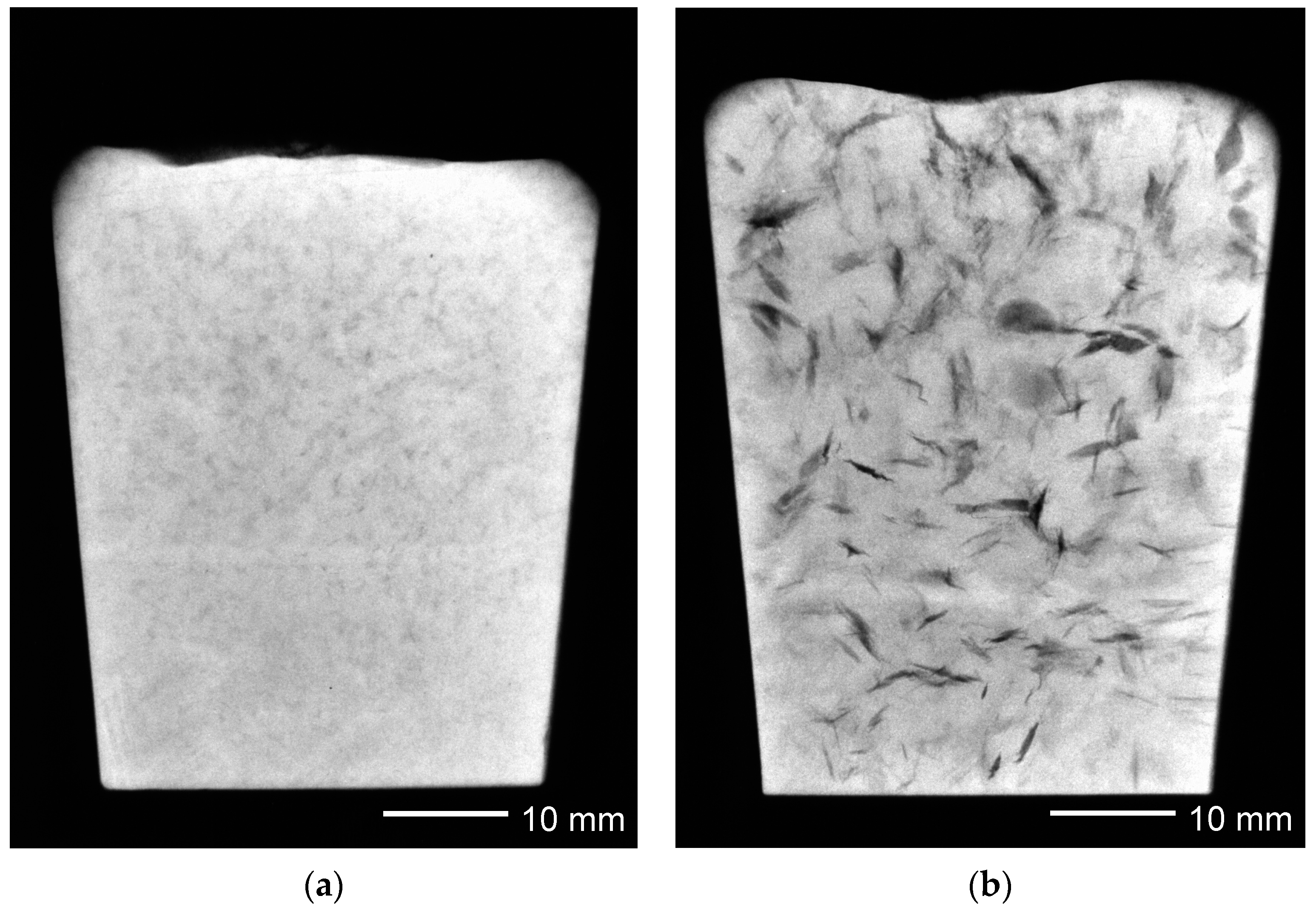
A population of bifilms in an aluminium alloy is shown in Figure 2. Figure 2a is the radiograph of the small sample of metal poured turbulently so that the bifilms are scrambled and ravelled into compact shapes, visible as faint shadows. Figure 2b shows the same metal poured at the same time into a mould over which a bell jar was placed and evacuated to reduce the pressure during cooling. The air trapped in the ‘air-gap’ of the bifilms is thereby expanded to unfurl the defects, showing their true sizes, in the region of 10–15 mm, in the radiograph.
In steels containing aluminium or chromium as a major alloying element, alumina-rich or chromia-rich oxide films can occur [2] which can become entrained as double films (bifilms) in the liquid alloys. Their presence has been confirmed in ultrasonic observations which have been used to monitor their number and size. At lower temperatures in nickel-based alloys containing aluminium, their presence is commonly seen on fracture surfaces, but in steels at higher temperatures and generally lower Al levels, the films have been thinner and often fragmented into particles by Oswald coarsening. In this disguise they have tended to escape identification as originally films [2]. (This point is taken up again later in the discussion of Figure 5).
This paper explores the possibility that the hot ductility of TWIP (twinning induced plasticity) and TRIP (transformation induced plasticity) steels may be explainable, at least in part, by the presence of casting defects although more experimental evidence is required to confirm such a theory.
The hot behaviour of these steels is dauntingly complex, so this author has relied extensively on the recent review by Mintz and Qaban [3]. These authors draw attention to the importance of the poor hot ductility of these steels which is seen in cracking behaviour during straightening subsequent to continuous casting, particularly when the Al is high (1.0–1.5%). This failure mode can be a major limitation to the use of these otherwise highly attractive engineering materials.
2. General Hot Cracking Background in Metals
There is a significant hot tear experiment [4] which has been carried out with the aluminium alloy A206 containing, among other elements, approximately 5%Cu. This alloy is infamous in the world of light alloy casting, being perhaps the most sensitive Al alloy to hot cracking during solidification. The experiment described here is an exemplary model of hot cracking in metal systems, and it related as a relevant background to the behaviour of steels. Both Al alloys and TWIP, and even TRIP steels are metallurgically similar having a face centred cubic (fcc) matrix before the straightening operation and the surface oxide on the liquid metal is expected to be alumina (Al2O3). The experiment was designed to show the difference in hot cracking behaviour in alloys with and without bifilms.
The hot tear behavior of the A206 alloy in this instance was assessed with the most severe of all the hot tear tests, the ring test, in which an annulus of liquid metal was poured into a ring groove around a central steel core and allowed to solidify [2]. As cooling progressed, the cast metal would contract on to the steel core, generating cracks. The hot tearing susceptibility was semi-quantitatively assessed by measuring the total length of cracks. For A206 alloy the total length of the numerous cracks would normally exceed 100 mm.
A second experiment was carried out in which the alloy was poured through a standard 20 ppi (pores per inch) ceramic foam filter to eliminate a proportion of its expected population of bifilms, and introduced into the moulded ring groove from underneath, to avoid turbulence (and avoid the potential re-introduction of bifilms) on entry to the mould. Four ring tests were cast in this way. When finally solidified, all four contained zero cracks, and were contracted on to the steel cores so tightly that they could not be removed. A206 alloy had never previously been cast in this severe test with zero crack results.
This result of zero failures in a highly hot-tear-prone alloy, employing a test designed to maximise hot cracking conditions during freezing, points strongly to the central importance of prior crack defects in the liquid metal.
The paradoxical feature of the bifilm cracks in the A201 aluminium alloy was that the cracks appeared to be brittle cracks, often taking the form of a kind of cleavage fracture, exhibiting minimal plasticity, but in a ductile matrix.
It is interesting therefore to ascertain, so far as possible, whether such a phenomenon may be occurring in the case of TRIP and TWIP steels.
3. Hot Ductility in TWIP and TRIP Steels
It is significant that Al is often a necessary alloying element to achieve the desired properties of TWIP and TRIP steels, but, perversely, has the worst influence on hot ductility [3]. Traditionally, this behaviour has been attributed to the presence of AlN on grain boundaries. Naturally, the AlN has been assumed to be brittle, since it leads to the familiar ‘rock candy’ fractures, in which the prior austenite grains, apparently largely un-deformed, are clearly revealed on the fracture surface (Figure 3).
Interpreting these well-known observations from a bifilm perspective, it is worth drawing attention to the fact that aluminium oxide bifilms are to be expected in liquid steels as a result of the turbulent handling of the liquid metal. If analogous observations from Al alloys apply to steels, the Al2O3 bifilms would form first, followed by AlN which would precipitate later, forming on the alumina substrates provided by the bifilms [2].
On a fracture surface, the precipitated AlN film would be sited on the underside of the thin oxide of the bifilm and would be viewed through the very thin oxide and would normally be overlooked. However, the presence of the oxide could be identified by careful observation in a scanning electron microscope, identifying the oxide by its folds and creases showing that it had been formed on a mobile liquid surface. Such oxide films appear to have been observed on fracture surfaces of TRIP 980 steel [5].
In most metal and alloy systems researched so far, it is the alumina (occasionally chromia) bifilms which form first in the liquid metal [6]. All precipitates of second phases, including carbides and nitrides such as AlN, appear to form subsequently and do so, on the bifilms as a favoured substrate. This is the reason for many carbides and nitrides in steels being seen to be associated with cracks. It has always been assumed that the cracks are due to cooling stresses. However, in view of the extreme strength of most carbides and nitrides, and their atom by atom deposition from solution, one would expect such structures to result in a solid, free from stress-raising defects, and therefore having no sites to initiate failure when stressed. There is little doubt (again with Al alloys and other alloys behaving similarly) that the cracks associated with carbides and nitrides appear because they have formed on a crack, a bifilm, as a favoured substrate. These cracks have not been formed by stress; they have formed by surface entrainment. There is now a large literature confirming this mechanism [2,7].
Hence, the turbulence of casting in air would be expected to produce double oxide films (not nitride films) based on Al2O3, and will take the form of cracks which have an oxidised internal surface.
The extraordinary and unique features of the bifilm consist in its exterior faces consisting of those interfaces which were the original underside of the surface oxide film on the liquid metal, which are therefore in perfect atomic contact with the liquid matrix, and perfectly wetted, in contrast to the interior interface which is perfectly non-wetted (Figure 1). This duality of ‘interior interfaces un-bonded but exterior interfaces perfectly bonded (to the matrix)’ appears to be central in the mechanical and chemical behaviour of the current quality problems with our metals.
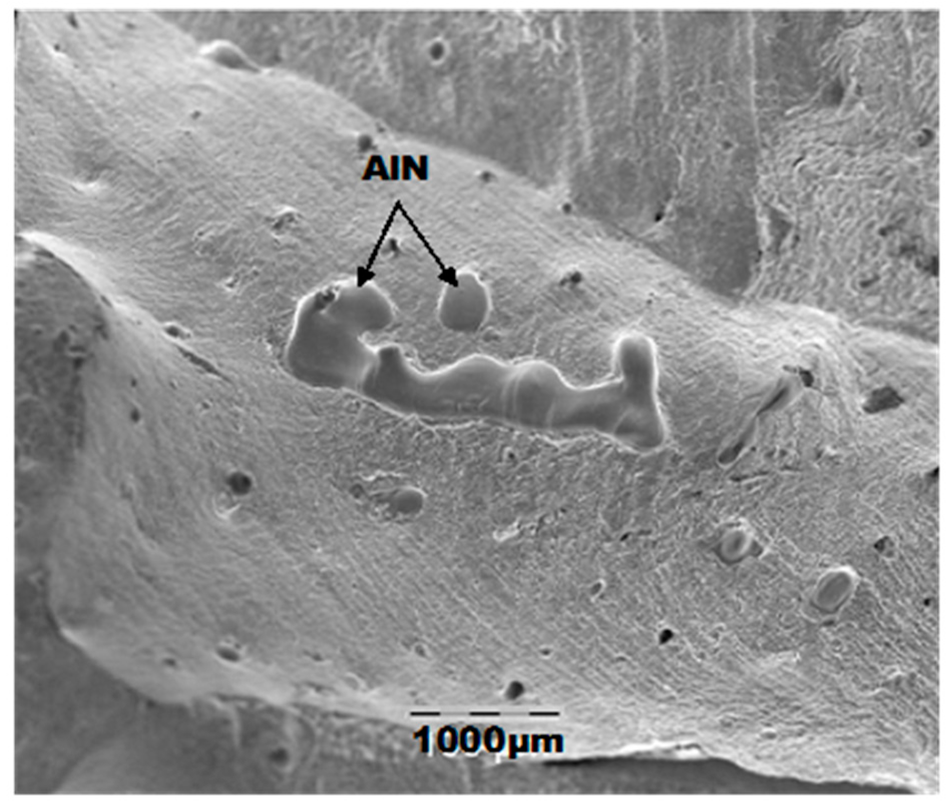
The exterior wetted interface seems to be a favoured substrate for the nucleation and growth of intermetallic and second phases, so if AlN is formed, it is most likely to precipitate on the outer surfaces of oxide bifilms (Figure 4) [2].
AlN might be formed even in the presence of low N in solution in the melt, because trapped air in the bifilm (in the ‘air gap’ between the microscopically rough dry oxide surfaces) might provide its 4/5ths of the entrained air (78%N, 21% oxygen) which would continue to react with the metal, thickening the existing oxide film with a layer of nitride [7]. The aluminium oxide/nitride interchanges have been intensively studied in Al alloys where it is now known that the oxide always forms first, and continues to grow while oxygen in available, but as soon as the oxygen is consumed, then the nitride forms [6]. Because air is mostly nitrogen, the nitride layer can be significantly thicker than the oxide and may obscure the oxide layer. On a fracture surface the nitride from entrained gaseous nitrogen in the air will appear uppermost, on top of the oxide. In contrast, if N in solution is sufficiently high to precipitate as a nitride, the nitride is almost certain to precipitate on the wetter outer surface of the oxide bifilm, so that on the fracture surface the nitride will appear below the oxide. In either case, the oxide is usually the thinner film so it appears that the AlN is the phase causing the fracture. However, once again, the oxide bifilm is the pre-existing crack, and the AlN would be expected to make a negligible contribution to the fracture.
On occasions, probably when the Al content is high, the thickness and stability of the alumina bifilms prevents this breakup under the driving force of reduction of surface energy, and simply remains as slabs of alumina and/or AlN (Figure 4).
At lower temperatures in the light alloys, the oxide films can be clearly seen and identified by their generally smooth surface, crossed with fine folds and ripples derived from its origin as a vanishingly thin film on the surface of a liquid.
In contrast, at steelmaking temperatures the morphology of very thin films is not stable. Because of the higher rate of diffusion in high temperature metals the film tends to break up into particles, coarsening to reduce its surface energy [2,7]. On a polished micrograph the continuous line of a sectioned film becomes separated as beads on a string. Figure 5 gives examples. In these cases, the separate inclusions may be separately nucleated inclusion particles on a fragmented bifilm. Alternatively, the bifilm remains inert and intact, but the inclusions have separated by the coarsening reaction. Just possibly, both the bifilm and inclusion films have together balled up to reduce their combined energies. Only careful research will elucidate the actual mechanism for the formation of this string of particles decorating the bifilms occupying the prior austenite grain boundaries.
The fractures along prior austenite grain boundaries are understandable, because during freezing, the growing austenite grains will push bifilms ahead (the grains cannot, of course, grow through the ‘air gap’ of the bifilms). On impinging against other grains, the bifilms will naturally be trapped at the boundary. In a real sense, the bifilms are the grain boundaries (Figure 1).
An analogous situation occurs in the solid state when recrystallisation occurs: a migrating boundary incurring a bifilm cannot cross its ‘air layer’. For this reason, the majority of bifilms exist in grain boundaries, leading to intergranular failures. Hence, TWIP steels with 0.75%Al and 1.5%Al as shown in Figure 14 of reference [3], numerous alumina bifilms are present causing grain boundary embrittlement and loss of ductility. The TWIP alloy without aluminium will have fewer and/or weaker bifilms, so boundaries will be enabled to migrate more easily, permitting some recrystallization, and so benefiting ductility.
Where recrystallization (or grain growth) occurs by the motion of boundaries at high temperatures, the eventual trapping of all the grain boundaries would bring recrystallization to a halt. At that stage, the continuing cooling strains will activate strain concentration in the grain boundaries, particularly in those boundaries which are composed of large areas of ‘air gap’. These weakened boundaries will shear first. The strain transfer to surrounding boundaries will subsequently tend to shear less weakened boundaries. The grain boundary sliding action will lead to failure, limiting ductility, as shown in Figure 6.
It is interesting that the excessive grain boundary sliding of the un-recrystallised austenite appears to reduce the hot ductility of TWIP steels. It seems probable that this can be understood in terms of the higher bifilm content of un-recrystallised boundaries which will have gathered their bifilms by impingement of the growing austenite grains in the solidifying liquid. Such boundaries will be incapable of migrating as in recrystallization, but will naturally slide easily if parts of the boundary are not in contact, but are separated by a microscopically thin ‘air layer’.
The interesting current confusion in the literature is illustrated by the fracture surface of the tensile test piece shown in Figure 7, which the authors interpret as AlN on the surface of a film. The film is most probably the half of an alumina bifilm, but probably not easily identifiable as alumina because of its extreme thinness. The globular features appear to be a liquid phase, which may have originated as a favoured precipitate on the bifilm (the wetted underside of the film as viewed in the image) but has exuded through holes and cracks in the film. Although the exudate is labelled as AlN, the AlN signal is probably confused by AlN which often precipitates favourably on alumina bifilms (once again on its wetted underside as seen in the image), and in such a thickness as to be easily identified by EDAX through the overlying thin alumina. In any case of course, AlN has a melting point over 2000 C whereas the exudate appears to be a phase with a melting point below that of the matrix steel. A careful re-examination would be worthwhile.
4. The Generation of Liquid Oxides
There appears to be good evidence from multiple sources that additions of extremely low levels of boron improve the hot ductility [2,7]. These levels are often much smaller than the levels of carbon which are required to make any significant contribution to normal alloying. Because boron and carbon are very similar interstitial elements in steels, the difference in response to ductility is surprising. For boron to act at such low levels is suggestive that the element is not acting as a normal alloy in a uniform solution, which would surely be too dilute to be effective, but must somehow be concentrated, akin to the action of a surface active element.
It seems likely that the action of boron is to react with the surface oxide alumina, reducing its melting point from over 2000 °C to below 1000 °C by forming a borate. It therefore liquefies the oxide. This has the dramatic result of eliminating the creation of bifilms when masses of liquid metal impinge or fold. Instead of the solid-oxide-to-solid-oxide impingement, the impingement is a liquid borate to another liquid borate. The impacting liquids fuse seamlessly, spherodise into droplets, and mainly float out. No bifilm is created. The danger of a dense population of cracks in the steel is avoided.
Incidentally, this action of small quantities of boron making significant benefits to hot cracking phenomena is corroborated by the widely observed action boron has on its enhancement of quench sensitivity in steels. The presence of a dense array of bifilms, with their residual air layer forming a barrier to heat flow, naturally lengthens the heat flux paths around the bifilms. The elimination of bifilms by a boron addition permits heat to flow directly down temperature gradients, without hindrance, hence faster and further during a quench, greatly increasing the depth of the quenching action.
Calcium addition is also helpful to reduce bifilm issues in many steels. Calcium oxide reduces the melting point of aluminium oxide to close to 1400 C, so that the liquid/liquid impingements during turbulence merely produce oxide droplets instead of bifilms. The great advance in steel production called ‘inclusion shape control’ [8] benefitted from the elimination of bifilms rather than, as assumed at the time, the greater sphericity of the final inclusion shapes. However, calcium may be relatively ineffective in TWIP and TRIP steels, being overwhelmed by the high levels of aluminium alloying addition, so that calcium additions are insufficient to deal with the masses of aluminium oxide. Having concluded this, this author wonders whether much higher levels of boron may be beneficial; this seems to be an unexplored area of alloying which may eliminate bifilm production to higher levels of aluminium, although, of course, the possibly of the unwanted introduction of penalties for other properties would require to be carefully tested. Even so, if the high boron deals effectively with the high alumina, little or no boron should remain in solution in the alloy; the boron will have achieved its purpose with minimal risk of unwanted side effects.
Manganese is another element which appears to eliminate bifilms in steel as a result of the low melting point of its oxide MnO2. Hadfield Manganese steel at 12 or 13% Mn is well known for its impressive toughness, permitting its use as cast railroad points which undergo massive punishment in service. Although its toughness is commonly attributed to its austenitic structure, it seems to this author that its low bifilm content may be the key important reason. TWIP steels would also be expected to benefit from their high Mn content as a result of this mechanism, although the presence of Al is a complication and may assist to retain the high melting point of the oxide on the liquid metal, as appears to be inferred by the cracks in the high Mn alloy shown in Figure 7 of M&Q’s review [3]! Research is very much needed on the melting points of mixed oxides for precise targeting of developments in steel production, free from damaging cracking problems.
5. Delayed Fracture
The phenomenon of delayed fracture exhibited in Figure 8. is curious. The 1.5%Al might have been expected to create more bifilms, and so lead to greater cracking, which is clearly not observed. The profusion of cracks in the Al-free alloy illustrate that some other element is responsible for bifilm development in this alloy. Also, the fractures take time to occur, strongly suggesting that hydrogen may be diffusing into the alloy, and precipitating into and forcing open the lengthy strain-extended bifilms.
The source of the hydrogen might be a lubricant or moisture in the environment, which reacts with the raw steel surface. In contrast, the Al-containing alloy would have a film of passivating alumina on its surface. Such passive oxides are known to be almost impermeable to hydrogen [11]. Effectively, the aluminium oxide protects the alloy against the ingress of hydrogen.
6. Summary
Many liquid steels, particularly many TRIP and TWIP steels, have solid, stable, high melting point surface oxides, such as alumina and chromia.
Many casting processes suffer from surface turbulence and air entrainment so that the dry surface oxides are folded-in to the liquid as double films, creating large, dense populations of bifilms, as cracks. The entrained bifilms are suspended in the liquid steel, and become frozen into the cast steel.
Hot ductility is predicted to be improved by
- Improved casting processes, avoiding pouring, or using improved pouring techniques, which can reduce the bifilm population by reducing surface turbulence and air entrainment during casting.
- Liquefying the surface oxide film on the liquid metal by the addition of certain alloying elements, particularly boron.
Vacuum melting and casting is predicted to be ineffective in reducing bifilm problems.
Funding
This research received no external funding.
Conflicts of Interest
The author declares no conflict of interest.
References
- Campbell, J. A Personal View of Microstructure and Properties of Al Alloys. Materials 2021, 14, 1297. [Google Scholar] [CrossRef] [PubMed]
- Campbell, J. Complete Casting Handbook; Butterworth & Heinemann: Oxford, UK, 2015. [Google Scholar]
- Mintz, B.; Qaban, A. The influence of precipitation and high levels of Al, Si, P as well as a small B addition on the hot ductility of TWIP and TRIP assisted steels. A critical review. Metals 2022, 12, 502. [Google Scholar] [CrossRef]
- Campbell, J. The Origin of Fracture—The Mechanisms of Metallurgical Failure; Butterworth Heinemann: Oxford, UK, 2020; pp. 180–181. [Google Scholar]
- Zhang, M.; Li, H.; Gan, B.; Zhao, X.; Yao, Y.; Wang, L. The Mechanisms of Metallurgical Failure: The Origin of Fracture. Metall. Mater. Trans. 2018, 49B, 1–12. [Google Scholar]
- Griffiths, W.D.; Raiszadeh, R. A Semi-empirical Mathematical Model to Estimate the Duration of the Atmosphere within a Double Oxide Film Defect in Pure Aluminum Alloy. Metall. Mater. Trans. 2008, 39B, 298–303. [Google Scholar]
- Chadwick, H. Complete Casting Handbook, 2nd ed.; Butterworth Heinemann: Oxford, UK, 2015; p. 426. [Google Scholar]
- Verma, N.; Pistorius, P.C.; Fruehan, R.J. Ca modification of spinel inclusions in Al-killed steel. Metall. Mater Trans. 2012, 43B, 830–840. [Google Scholar] [CrossRef]
- Comineli, O.; Qaban, A.; Mintz, B. Influence of Cu and Ni on the hot ductility of low C steels with respect to the straightening operation when continuous casting. Metals 2022, 12, 1671. [Google Scholar]
- De Cooman, B.C.; Chin, K.G.; Kim, J. High Mn TWIP steels for automotive applications. New Trends Dev. Automot. Syst. Eng. 2011, 1, 101–128. [Google Scholar]
- Schomberg, K.; Grabke, H.J. Hydrogen permeation through oxide and passive films on iron. Steel Res. 1997, 67, 565–572. [Google Scholar] [CrossRef]
Figure 1.
Turbulence in the liquid, causing entrainment of the surface oxide creating bifilms and bubbles.
Figure 1.
Turbulence in the liquid, causing entrainment of the surface oxide creating bifilms and bubbles.

Figure 2.
Radiographs of a single sample of liquid Al alloy solidified (a) at atmospheric and (b) reduced pressure to open and reveal bifilms [2].
Figure 2.
Radiographs of a single sample of liquid Al alloy solidified (a) at atmospheric and (b) reduced pressure to open and reveal bifilms [2].

Figure 3.
The fracture surface of a tensile specimen of a TRIP steel fractured at 800 °C. (The central hole is the site of a thermocouple sheath) [3].
Figure 3.
The fracture surface of a tensile specimen of a TRIP steel fractured at 800 °C. (The central hole is the site of a thermocouple sheath) [3].

Figure 4.
“Rock candy” fracture in a TRIP steel containing 1.05%Al [3].
Figure 4.
“Rock candy” fracture in a TRIP steel containing 1.05%Al [3].

Figure 5.
(a) Line of MnS inclusions situated at pre-existing austenite grain boundary, with a high Cu-rich rim (black areas) in a TRIP steel with 0.5%Cu tested at 800 °C [7]. (b) Nb-Ti carbo-nitrides in a B-containing Al TWIP tested at 1000 °C [3].

Figure 6.
Hot ductility curve for a 0.4%C plain C-Mn steel tested at strain rate of 3 × 10⁻⁴ s−1 having no micro-alloying precipitates present showing all the different regions that are possible in the trough on cooling down through the austenitic temperature range, region (i) deformation induced recrystallized austenite; (ii) un-recrystallized austenite undergoing grain boundary sliding; (iii) DIF (deformation induced ferrite) [3].

Figure 7.
Room temperature fracture surface of a high Al, TWIP steel (0.6C, 18Mn 1.6Al, 0.007N) [3].
Figure 7.
Room temperature fracture surface of a high Al, TWIP steel (0.6C, 18Mn 1.6Al, 0.007N) [3].


Publisher’s Note: MDPI stays neutral with regard to jurisdictional claims in published maps and institutional affiliations. |
© 2022 by the author. Licensee MDPI, Basel, Switzerland. This article is an open access article distributed under the terms and conditions of the Creative Commons Attribution (CC BY) license (https://creativecommons.org/licenses/by/4.0/).
Share and Cite
MDPI and ACS Style
Campbell, J. The Hot Ductility of TWIP and TRIP Steels—An Alternative Interpretation. Metals 2022, 12, 2134. https://doi.org/10.3390/met12122134
AMA Style
Campbell J. The Hot Ductility of TWIP and TRIP Steels—An Alternative Interpretation. Metals. 2022; 12(12):2134. https://doi.org/10.3390/met12122134
Chicago/Turabian StyleCampbell, John. 2022. "The Hot Ductility of TWIP and TRIP Steels—An Alternative Interpretation" Metals 12, no. 12: 2134. https://doi.org/10.3390/met12122134
Note that from the first issue of 2016, this journal uses article numbers instead of page numbers. See further details here.