Article

The Effect of Thickness on Strength of Single Lap Orbital Riveted Aluminum/Composite Joints Used in Marine Environments

Department of Engineering, University of Messina, Contrada di Dio 1, 98166 Messina, Italy
*
Author to whom correspondence should be addressed.
Metals 2022, 12(12), 2068; https://doi.org/10.3390/met12122068
Submission received: 24 October 2022 / Revised: 24 November 2022 / Accepted: 28 November 2022 / Published: 1 December 2022
(This article belongs to the Special Issue Environmental Effect on Metal Joining)

Abstract

:
In an innovative vision of manufacturing, orbital riveting is a joining technique characterized by high efficiency, energy saving, low costs and low noise. It is a cold forming process where a tool rotates at a fixed angle (i.e., typically 3° to 6°) to create a sweeping line of pressure around a rivet. This movement progressively promotes, with each rotation, the collapse of the rivet shank down onto the upper substrate of a joint, permanently forming a rivet head. The aim of this research is to make and test multi-material joints between an aluminum AA5083 H111 sheet and a glass fiber reinforced laminate. Specifically, nine configurations of single lap joints were studied by investigating the effect of the thickness (i.e., 2.5, 3.0 and 4.0 mm for the aluminum and 2.5, 3.0 and 4.0 mm for the composite laminate) both on the mechanical characteristics and on the failure modes.

Graphical Abstract

1. Introduction

The growing demand for lightweight and safe structures, characterized by high strength and durability, has led to the increasing use of composite materials and aluminum in many industrial applications in fields such as aerospace, automotive and naval [1,2,3]. Composite materials have been used since the mid-1980s to reduce acquisition and maintenance costs and improve the structural and operational performance of naval craft in superstructures, decks, bulkheads, propellers and so on [4]. Aluminum alloys are used for their many advantages in the shipbuilding industry compared with steel, such as a reduction of the weight (with a total reduction of up to 65%) and better corrosion properties [5].
In this framework, the design of the composite/metal joint is one of the most critical aspects [6]; in fact, one of the consequences of the differences between these materials, in term of both mechanical and physical properties, is simply the limit in the joining technology [7]. The mechanical properties of composite materials drop down when they are drilled and bolted, due to the stress concentration produced by the fastener holes. For this reason, the failure behavior of the mechanically fastened joints has been the focus of attention over the last several decades. Shan et al. [8] proposed a new progressive fatigue damage model and studied the influence of the thickness ratios of the joined plates on the competing fatigue failure of the joint, determining a critical thickness ratio corresponding to the transition of the failure mode. Montagne et al. [9] performed a failure analysis on aluminum/composite bolted joints, optimizing the main geometrical parameters to avoid the structural failure.
In particular, the thickness of the substrates to be connected is a critical geometrical parameter that influences the performance of the joint. Liu et al. [10] investigated both the joining process and the failure mechanisms of self-piercing riveted joints between carbon fiber reinforced polymer (CFRP) composites and AA5754 aluminum alloy by varying the thickness of the composite sheet. They found that with an increase in CFRP thickness, the damage degree decreased. Cui et al. [11] studied the effect of the CFRP thickness joined to a 5182 aluminum alloy through a process of electromagnetic riveting. They found that by increasing the CFRP thickness, the applied load in a single lap shear test increased rapidly and the peak load of the failure increased gradually. Moreover, the time of the peak load became lag, and displacement of the failure process was reduced. Finally, the main failure position was transferred from the CFRP sheet to the aluminum plate and rivet. Lee et al. [12] evidenced how the failure mode, in a clinching process, changes with the composite substrate thickness.
Among the employed technologies for joining dissimilar and non-metallic materials, different studies were conducted on self-piercing riveting [13,14] and clinching [15,16]. Several authors, to overcome the stress concentration due to the fastener hole, proposed hybrid (bonded/bolted) joining technology [17]; Zhang et al. [18] conducted experimental and numerical investigations demonstrating the advantages of using polyurethane adhesive in comparison with mechanically fastened joints and bonded joints.
A new joining process is represented by orbital forming, which achieves better results at lower costs [19]. The tool, similar to impact and compression forming, applies a compressive axial load to the rivet to join the parts. Moreover, it rotates at a fixed angle (generally 3 to 6°), applying both axial and radial forces to obtain its plastic deformation. This peculiarity leads to the necessity of several tool revolutions, taking 1.5 to 3 s to complete the orbital forming process. During the process, the deformation work only concerns the line of contact between the tool and the rivet, reducing the axial loads by about 80%.
Compared to the other joining techniques, this type of process offers the following strengths:
  • Less stress on the joined components;
  • A smooth surface of the finished components;
  • The elimination of cracks caused by impact rivets;
  • No bending or swelling of the fastener shank due to cold-head forming;
  • Fewer rigid fixtures and longer lasting tools;
  • The use of smaller presses and therefore reduced sizes (dimensions) and costs.
On the other hand, the application of the process is limited by the necessity to have access on both sides of the parts to be joined; moreover, the sheets—two or more—must be pre-drilled for the rivet insertion.
This joining technology represents a new vision in manufacturing, including just-in-time (JIT) manufacturing and measurable process control and the requirement of a joint with less residual stress, which can be employed with different materials, i.e., metals (ferrous and nonferrous) and plastics [20].
Despite these strengths, this topic is rarely discussed in the literature and only few researchers have addressed it recently.
Di Bella et al. [21] studied the durability of steel–aluminum orbital riveted joints in salt spray fog based on other studies conducted on various joining techniques of dissimilar materials: self-piercing riveting, clinching, and clinch-bonding. They observed that the mechanical behavior of the joints is influenced by both the corrosion time and the configuration (i.e., the position of the rivet). In particular, the joint configuration affects both of the failure modes for the untreated samples and the total resistance.
Another study by Di Bella et al. [22] investigated the effects of some geometrical aspects such as sheet thickness and rivet diameter on aluminum joints produced by the orbital forming technique. The main results demonstrated that the symmetry in the joint geometry, by reducing bending phenomena, leads to unbuttoning during tensile tests. For asymmetrical joints it is possible to observe a transition from shear-out to net tension at the increasing of the diameter of the rivet. Finite element analysis both of the orbital riveting process and of the single lap shear test have been performed with a good agreement with experimental results, so a model is proposed to design the joints based on the industrial application requirements. Finally, a failure map predicting fracture for different hole diameters was constructed based on the experimental results.
In naval applications, the joining of dissimilar materials is a critical factor in ensuring a good mechanical performance to weight ratio. Therefore, it is strategic to investigate other technologies that are widely used in other fields.
Thus, the aim of this experimental work is to investigate both the mechanical performances and failure modes of a glass fiber reinforced composite and aluminum AA5083 H111 joints fabricated by orbital riveting, for use in maritime applications.
Specifically, nine different configurations of single-lap joints were fabricated and tested to evaluate the effect of substrate thickness on the joint performances.
Finally, a statistical analysis was performed to further study the influence of the substrates on the results.

2. Experimental Setup

2.1. Material properties

The materials were selected based upon those most common in naval industry. For the selection of the aluminum alloy the main criteria were: (i) great corrosion strength; (ii) high machinability; (iii) low specific weight. These characteristics are well represented by aluminum AA5083 subjected to the heat treatment H111, which is suitable for using in naval applications (i.e., fast sea transportation for commercial and military applications). It is a medium-strength and non-heat-treatable wrought aluminum alloy with magnesium (4.0% to 4.9%) and traces of manganese (0.4% to 1.0%) and chromium (0.05–0.25% max). Its strength increases with increasing Mg content. It is highly resistant to attack by seawater and industrial chemicals. Moreover, it retains exceptional strength after welding.
While a typical glass fiber reinforced composite was used for the composite substrate, the focus was on the type of resin: among the most used thermosetting resins, the unsaturated polyester was the most suitable because of its affordability and versatility. The reinforcement consists of the combination of two layers of mat and woven, that change their areal weight depending on the thickness:
-
Mat 700 g/m2 + woven 500 g/m2 for 2.5 mm thickness,
-
Mat 900 g/m2 + woven 500 g/m2 for 3 mm thickness,
-
Mat 1300 g/m2 + woven 500 g/m2 for 4 mm thickness.
Table 1 and Table 2 summarize the principal mechanical characteristics of the employed substrates.
Finally, the rivets were made of aluminum alloy AA2011. It is an age-hardening material that can be well manufactured both to very close tolerances and with a smooth and bright finish. Moreover, it shows good mechanical properties (see Table 1).

2.2. Geometry

The specimens were manufactured following ASTM D5961 standard [23]. Figure 1 reports the geometry of the sheets to be joined—both of them were pre-drilled—and Figure 2 reports the geometry of the rivet. Specifically, the rivets were manufactured with a turning center Yamazaki Mazak—Quick Turn Nexus 200MY (Yamazaki Mazak Italia Srl, Milan, Italy).
Nine symmetric (i.e., same thickness of aluminum and composite sheets) and asymmetric (i.e., different thickness) joint configurations were manufactured, as summarized in Table 3, based on the needs of some companies involved in the research project THALASSA, funded on the National Operational Programme on Research and Innovation 2014/20020. In particular, the Azimut Benetti Group provided information on the composite materials (i.e., lamination sequences and thicknesses); in turn, Intermarine SpA provided the materials and some application practices for the joining in terms of geometry (i.e., the thickness of the substrates).
All the manufactured samples were identified using the code Ax-Cy, where x represents the thickness of the aluminum substrate and y the thickness of the composite one.

2.3. The Orbital Forming Joining Process

The joints were manufactured with a BK-TAUMEL “BK80” machine [24]. In particular, the forming tool, mounted off-center in the rotating spindle, was inclined to a 5° angle toward the center of the spindle.
In this specific case, the attention was focused on the effect of the substrate’s thickness configuration, keeping constant the technical parameters of the process. For this reason, a preliminary study to obtain the correct parameters (i.e., punch force, working time and displacement of the punch) was conducted. A surface graph of the tensile max load with the same rivet dimension and total thickness of the substrates was evaluated with variations of the above mentioned three parameters. Consequently, the following setup parameters were used to make all samples: displacement of the punch equal to 0.8 mm, working time of 3 s and punch force equal to 0.9 KN.
The views and the section of the manufactured joint are depicted in Figure 3.

2.4. Test Setup

Orbital riveted joints samples were tested through a Zwick/Roell Z600 testing machine (ZwickRoell AG, Ulm, Germany) with a 600 kN load cell, equipped with a 10 kN load cell, in accordance with ISO/CD 12996 [25]. The crosshead rate was set equal to 1 mm/min. For each configuration five samples were tested. During these tests, load–displacement curves were acquired and, at the end, the related failure modes were recorded.

3. Results and Discussion

Figure 4 shows the representative load–displacement curves for each configuration. In all the tests, after an initial settlement, the load shows a quasi-linear increase until it reaches the maximum value, and it then drastically decreases.
In most cases the failure mode, classified according to ASTM D5961 [23], is for net tension (Figure 5a), this last occurs because the area of cross section is small. It is worth noting that in the present experimental campaign, the failure interests only the composite substrate.
This can be explained by the fact that the tensile resistance of the laminate sheets is lower than that of the aluminum ones, and their behavior is typical of a brittle material, thus leading to a premature rupture with respect to the aluminum alloy.
Even if an increase in thickness produces an increase in area, the final value is still too small to induce a transition towards another fracture mode. Thus, it is not always obvious that a change in the joint geometry can lead to different failure modes [19].
In some cases, the failure occurs for cleavage (Figure 5b), which can be regarded as a mixed failure mode between net tension and shear out. This is mainly influenced by the orientation of the composite fibers in the load direction, i.e., especially by the presence of the oriented fibers of the woven layer.
By analyzing the experimental curves of symmetric joints, it is possible to highlight that both maximum load and ultimate displacement increase as the total thickness of the joint increases, whereas for asymmetric joints, the effect of thickness is less evident. This experimental behavior is further investigated through the statistical analysis in the next section.
Table 4 resumes the use of the mean values of maximum load, displacement at the maximum load and failure modes of the fiberglass composite, for all the configurations.

4. Statistical Analysis

The ANOVA of the maximum load and displacement (“Load [N]” and “Disp [mm]”, respectively) data was conducted by means of the MINITAB® software (v17.1.0, Minitab LCC, State College, PA, USA), considering two factors: the thickness of aluminum alloy (named “AA5083”) and the thickness of composite (named “Comp”), both with three levels (i.e., 2.5, 3.0 and 4.0 mm), as summarized in Table 5.
The results are reported in Table 6 and Table 7 for maximum load and displacement, respectively.
DF represents the degrees of freedom, used to calculate the mean square (MS). In general, they measure how much ‘independent’ information is available to calculate each sum of squares (SS). This sum of squares, also called sum of the squared deviations, measures the total variability in the data, which is made up of the following sources: (i) the SS for each of the two factors, which measures how much the level means differ within each factor; (ii) the SS for the interaction, that measures how much the effects of one factor depend on the level of the other factor and (iii) the SS for error, that measures the variability that remains after the factors and interaction are taken into account. The MS is simply the SS divided by the degrees of freedom. The MSs for error is an estimate of the variance in the data left over after differences in the means were accounted for. F is used to determine the p-value (p) that defines if the effect for a term is significant: i.e., if p is less than or equal to a selected level (i.e., 0.05, corresponding to a 95% level of confidence), the effect for the term is significant [26].
From the results in Table 6, it is evident that the value of probability is less than the value of 0.05, which indirectly proves that the developed model is satisfactory [27]. Consequently, it is possible to affirm that both variables have an effect on the maximum load, but that the composite is the most significant one. Furthermore, from the analysis of Table 5, it can be stated that both aluminum and composite are equally significant on the displacement.
The distribution of data and residual were checked showing normal distribution and random distribution of residuals versus fits (see Figure 6); the S value is very low with respect to the values of the response variable, showing a good description of the model of the response. The R2 value is the percentage of variation in the response explained by the model.
The values of about 70% for the maximum load and the displacement (i.e., 71.13% and 68.27%, respectively) indicate that 70% of the variation in the investigated variables is explained by the variation in the thickness of aluminum and composite. This means that there are other factors that could be considered in the analysis that can affect the maximum load or the displacement, though these are not ones that we investigated. By increasing the number of variables, the R2 value should increase [28].
The Two-Way Analysis of Means (ANOM) was aimed to show the interaction effects, as well as the main effects for both the first factor and the second factor. The plots have a centre line and decision limits. If a point falls outside the decision limits, then there is significant evidence that the mean represented by that point is different from the overall mean of the sample. If the interaction effects are statistically significant, it is not possible to interpret the main effects without considering the interaction effects.
From the analysis of the Two Way ANOM for Max Load (Figure 7) it is possible to conclude that there is no interaction between the two factors (aluminum and composite substrates); furthermore, in individually analyzing the main effects of the two factors it can be stated that only the composite variable significantly influences the max load data.
In contrast, studying the Two Way ANOM for displacement reveals an interaction between the two factors; all factors’ levels determine significant changes in displacement.
The above-mentioned results can be further confirmed by the interaction plots in Figure 8; when there is an intersection between two or more curves, then the factors cannot be considered independent of each other.
Furthermore, in the left bottom diagram it is evident that the loads increase with the increasing of the thickness of the composite substrate, i.e., the curves of higher thickness are placed above the others, while in the right upper diagram the curves are overlapped with the varying of the thickness of the aluminum.
While the load carrying capacity is mainly influenced by the thicknesses of composite substrate, the displacement has been determined by the coupling of both substrates.
The graphic representation of the first and third quartile data in the boxplot of loads (see Figure 9) clearly shows the effect of the composite’s increasing thickness.

5. Conclusions

In the present research, orbital riveted joints between a glass fiber reinforced composite and aluminum AA5083 H111 were tested. Nine configurations of single lap joints were realized to investigate the effect of thickness (2.5, 3.0 and 4.0 mm for the aluminum and 2.5, 3.0 and 4 mm for the composite laminate) on both the mechanical resistance and failure modes.
The experimental campaign has led to the following main results:
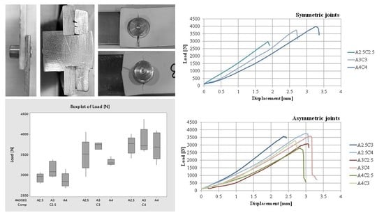
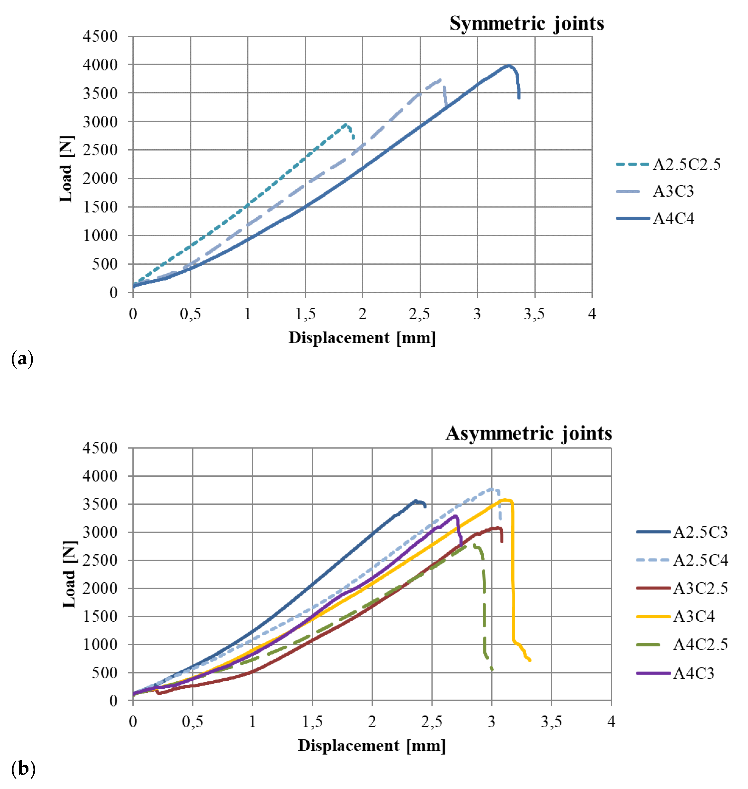
  • In regards to the symmetrical joints, both the maximum load and displacement increase with an increase of the total thickness (i.e., loads: 2932.6, 3772.9, and 3376.9 N; displacements: 2.18, 2.77 and 3.41 mm for A2.5-C2.5, A3-C3 and A4-C4 samples, respectively).
  • For asymmetrical joints, this effect of the thickness is less evident.
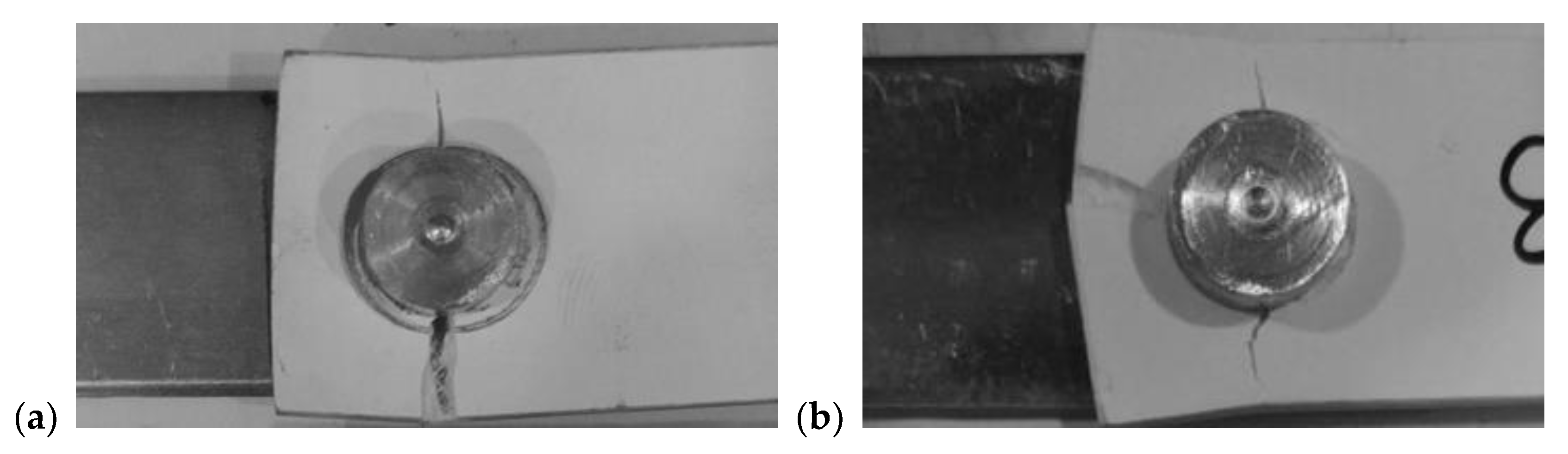
  • The failure always occurs on the composite substrate, by net tension or net tension/cleavage, showing the critical issue of the laminate cross-section and the influence of the fiber orientation along the tensile direction.
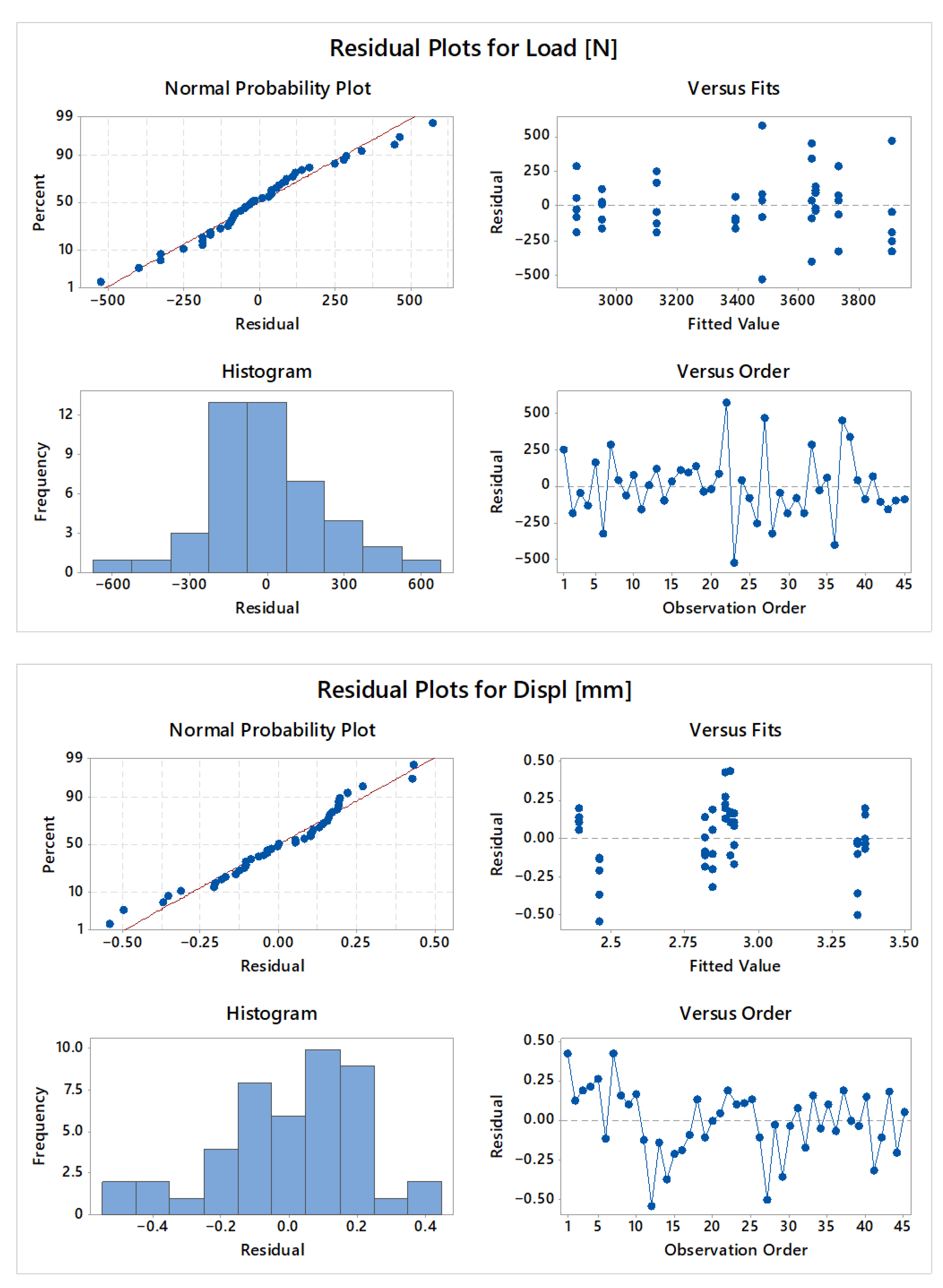
  • The ANOVA performed on the experimental data demonstrates a clear effect of the two substrates’ thicknesses on the final load, mainly due to the composite one—that is, the one directly affected by the fracture.
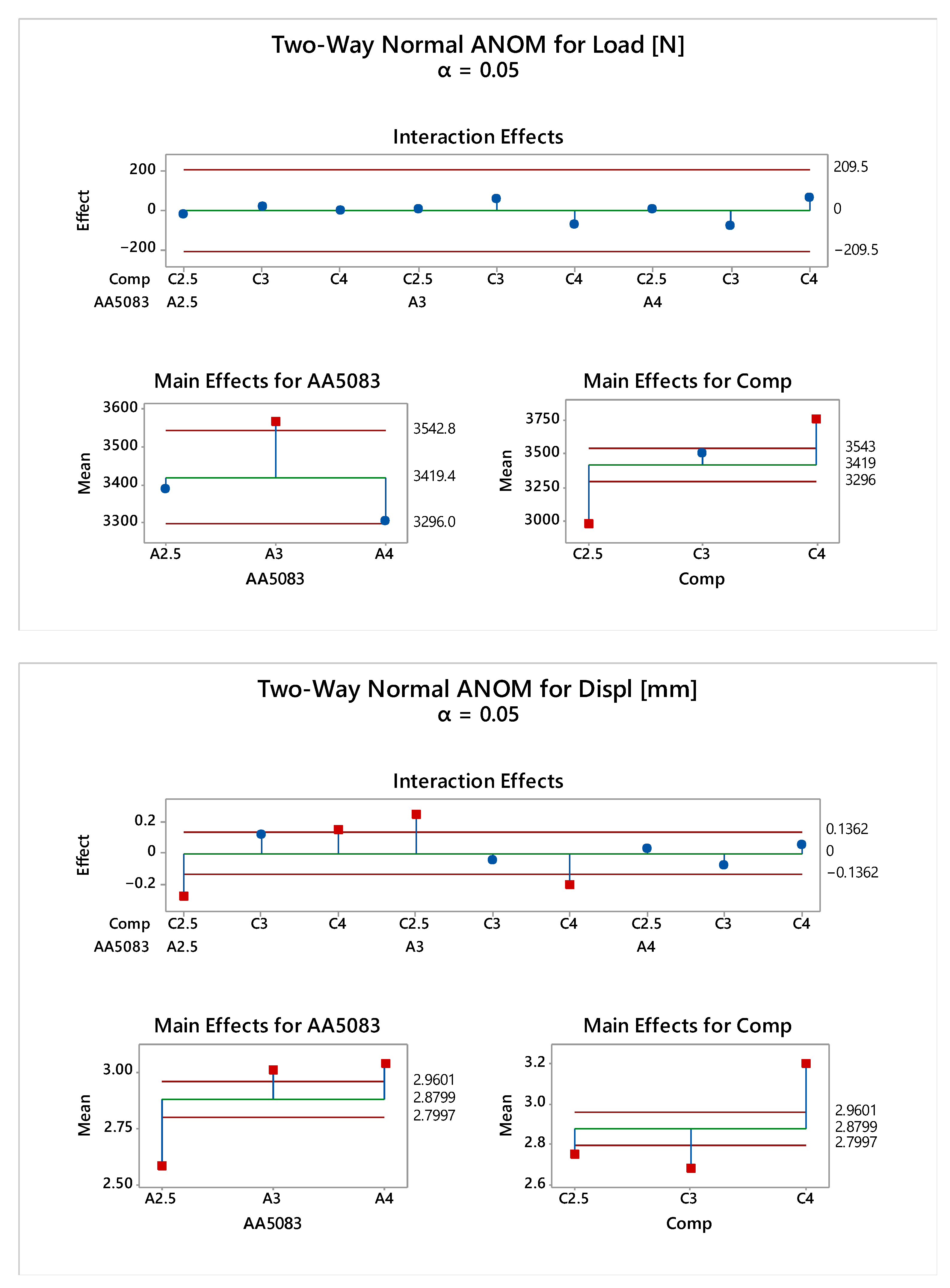
  • The Two-Way ANOM for maximum loading indicates that there is no interaction between the two factors (aluminum and composite substrates). Furthermore, when the main effects of the two factors are analyzed separately, we found that only the composite thicknesses significantly affected the maximum load data (in particular, the load increases with thickness, whether the joint is symmetrical or not). This confirms the critical importance of the laminate thickness, which is a key element in the design of this kind of joint configuration.

Author Contributions

Conceptualization, G.D.B. and C.B.; methodology, G.D.B. and C.B.; software, T.A. and F.F.; validation, T.A.; formal analysis, G.D.B. and C.B.; investigation, G.D.B.; T.A. and C.B.; resources, G.D.B.; data curation, T.A.; writing—original draft preparation, T.A.; writing—review and editing, G.D.B. and T.A.; visualization, G.D.B.; supervision, C.B.; project administration, G.D.B.; funding acquisition, G.D.B. and C.B.. All authors have read and agreed to the published version of the manuscript.

Funding

This research was funded by the Italian Ministry of University and Research on the National Operational Programme “Research and Innovation” 2014–2020 as part of the project “TecHnology And materials for safe Low consumption And low life cycle cost veSSels And crafts (THALASSA)”, grant number ARS01_00293.

Data Availability Statement

Not applicable.

Conflicts of Interest

The authors declare no conflict of interest. The funders had no role in the design of the study; in the collection, analyses, or interpretation of data; in the writing of the manuscript; or in the decision to publish the results.

References

  1. Le Lay, F.; Gutierrez, J. Improvement of the fire behaviour of composite materials for naval application. Polym. Degrad. Stab. 1999, 64, 397–401. [Google Scholar] [CrossRef]
  2. Hassoon, O.H.; Tarfaoui, M.; El Moumen, A. Progressive damage modeling in laminate composites under slamming impact water for naval applications. Compos. Struct. 2017, 167, 178–190. [Google Scholar] [CrossRef] [Green Version]
  3. Gaiotti, M.; Ravina, E.; Rizzo, C.M.; Ungaro, A. Testing and simulation of a bolted and bonded joint between steel deck and composite side shell plating of a naval vessel. Eng. Struct. 2018, 172, 228–238. [Google Scholar] [CrossRef]
  4. Mouritz, A.P.; Gellert, E.; Burchill, P.; Challis, K. Review of advanced composite structures for naval ships and submarines. Compos. Struct. 2001, 53, 21–41. [Google Scholar] [CrossRef]
  5. Gupta, S.; Singh, D.; Yadav, A.; Jain, S.; Pratap, B. A comparative study of 5083 aluminium alloy and 316L stainless steel for shipbuilding material. Mater. Today Proc. 2020, 28, 2358–2363. [Google Scholar] [CrossRef]
  6. Green, E. Design Guide for Marine Applications of Composites; Ship Structure Committee: Washington, DC, USA, 1997. [Google Scholar]
  7. Pramanik, A.; Basak, A.K.; Dong, Y.; Sarker, P.K.; Uddin, M.S.; Littlefair, G.; Dixit, A.R.; Chattopadhyaya, S. Joining of carbon fibre reinforced polymer (CFRP) composites and aluminium alloys—A review. Compos. Part A 2017, 101, 1–29. [Google Scholar] [CrossRef] [Green Version]
  8. Shan, M.; Zhao, L.; Liu, F.; Qi, D.; Zhang, J. Revealing the competitive fatigue failure behaviour of CFRP-aluminum twobolt, double-lap joints. Compos. Struct. 2020, 244, 112166. [Google Scholar] [CrossRef]
  9. Montagne, B.; Lachaud, F.; Paroissien, E.; Martini, D.; Congourdeau, F. Failure analysis of single lap composite laminate bolted joints: Comparison of experimental and numerical tests. Compos. Struct. 2020, 238, 111949. [Google Scholar] [CrossRef]
  10. Liu, Y.; Zhuang, W.; Luo, Y.; Xie, D.; Mu, W. Joining mechanism and damage of self-piercing riveted joints in carbon fibre reinforced polymer composites and aluminium alloy. Thin-Walled Struct. 2023, 182, 110233. [Google Scholar] [CrossRef]
  11. Cui, J.; Dong, D.; Zhang, X.; Huang, X.; Lu, G.; Jiang, H.; Li, G. Influence of thickness of composite layers on failure behaviors of carbon fiber reinforced plastics/aluminum alloy electromagnetic riveted lap joints under high-speed loading. Int. J. Impact Eng. 2018, 115, 1–9. [Google Scholar] [CrossRef]
  12. Galińska, A.; Galiński, C. Mechanical Joining of Fibre Reinforced Polymer Composites to Metals—A Review. Part II: Riveting, Clinching, Non-Adhesive Form-Locked Joints, Pin and Loop Joining. Polymers 2020, 12, 1681. [Google Scholar] [CrossRef] [PubMed]
  13. Liu, Y.; Zhuang, W. Self-piercing riveted-bonded hybrid joining of carbon fibre reinforced polymers and aluminium alloy sheets. Thin-Walled Struct. 2019, 144, 106340. [Google Scholar] [CrossRef]
  14. Wang, J.; Zhang, G.; Zheng, X.; Li, J.; Li, X.; Zhu, W.; Yanagim, J. A self-piercing riveting method for joining of continuous carbon fiber reinforced composite and aluminum alloy sheets. Compos. Struct. 2021, 259, 113219. [Google Scholar] [CrossRef]
  15. Menghari, H.G.; Babalo, V.; Fazli, A.; Soltanpour, M.; Ziaeipoor, H. A study on the electro-hydraulic clinching of aluminum and carbon fiber reinforced plastic sheets. Int. J. Lightweight Mater. Manuf. 2020, 3, 239–249. [Google Scholar] [CrossRef]
  16. Wang, J.; Yu, Y.; Fu, C.; Xiao, H.; Wang, H.; Zheng, X. Experimental investigation of clinching CFRP/aluminum alloy sheet with prepreg sandwich structure. J. Mater. Process. Technol. 2020, 277, 116422. [Google Scholar] [CrossRef]
  17. Zhang, H.; Zhang, L.; Liu, Z.; Qi, S.; Zhu, Y.; Zhu, P. Numerical analysis of hybrid (bonded/bolted) FRP composite joints: A review. Compos. Struct. 2021, 262, 113606. [Google Scholar] [CrossRef]
  18. Zhang, H.; Zhang, L.; Liu, Z.; Zhu, P. Research in failure behaviors of hybrid single lap aluminum-CFRP (plain woven) joints. Thin-Walled Struct. 2021, 161, 107488. [Google Scholar] [CrossRef]
  19. Patel, V.; Rathod, H.; Lalit, V.; Pratik, P.; Vipul, P. Design and manufacturing of orbital riveting machine (ORM). Int. J. Adv. Res. Eng. Sci. Technol. 2017, 4, 136–142. [Google Scholar]
  20. Jagtap, S.; Kavade, M. Orbital Riveting—A design and development of new machine. Int. J. Mech. Prod. Eng. Res. Dev. 2014, 2, 6–10. [Google Scholar]
  21. Di Bella, G.; Borsellino, C.; Calabrese, L.; Proverbio, E. Durability of orbital riveted steel/aluminium joints in salt spray environment. J. Manuf. Process. 2018, 35, 254–260. [Google Scholar] [CrossRef]
  22. Di Bella, G.; Calabrese, L.; Borsellino, C.; Alderucci, T. Effect of Sheets’ Thickness and Rivet Geometry on Mechanical Properties of Orbital Riveted Aluminium Joints: Experimental and Numerical Analysis. J. Manuf. Mater. Process. 2021, 5, 102. [Google Scholar] [CrossRef]
  23. ASTM D5961/D5961M-17; Standard Test Method for Bearing Response of Polymer Matrix Composite Laminates. American Society for Testing and Materials (ASTM): West Conshocken, PA, USA, 2017.
  24. Taumel Homepage. Available online: https://www.taumel.com (accessed on 3 March 2021).
  25. ISO 12996:2013; Mechanical Joining—Destructive Testing of Joints—Specimen Dimensions and Test Procedure for Tensile Shear Testing of Single Joints. ISO: Geneva, Switzerland, 2013.
  26. Di Bella, G.; Palomba, G. Cork/aluminium double-layer sandwich panels under impact loading for lightweight ship structures. Int. J. Crashworthiness 2022. [Google Scholar] [CrossRef]
  27. Satheesh, C.; Sevvel, P.; Kumar, R.S. Experimental Identification of Optimized Process Parameters for FSW of AZ91C Mg Alloy Using Quadratic Regression Models. Stroj. Vestn.-J. Mech. Eng. 2020, 66, 736–751. [Google Scholar]
  28. Chicco, D.; Warrens, J.; Jurman, G. The coefficient of determination R-squared is more informative than SMAPE, MAE, MAPE, MSE and RMSE in regression analysis evaluation. Peer. J. Comput. Sci. 2021, 7, 623. [Google Scholar] [CrossRef] [PubMed]
Figure 1. Geometry of the aluminum and composite substrates [mm].
Metals 12 02068 g001
Figure 2. Geometry of the manufactured rivet [mm].
Metals 12 02068 g002
Figure 3. Orbital riveted composite/aluminum joints.
Metals 12 02068 g003
Figure 4. Typical load–displacement trend of the orbital riveted joints. (a) Symmetric joints. (b) Asymmetric joints.
Metals 12 02068 g004
Figure 5. Failure modes. (a) Net tension. (b) Cleavage.
Metals 12 02068 g005
Figure 6. Residual plots for max load and displacement.
Metals 12 02068 g006
Figure 7. Two-Way ANOM for max load and displacement by aluminum, composite.
Metals 12 02068 g007
Figure 8. Interaction for max load and displacement by aluminum, glass.
Metals 12 02068 g008
Figure 9. Boxplot of max load by aluminum, composite.
Metals 12 02068 g009
Table 1. AA5083 H111 Aluminum mechanical properties.
SubstrateYoung’s Modulus
[GPa]
Ultimate Tensile
Strength [MPa]
Elongation
at Break [%]
Density
[g/cm3]
Aluminum7125022.02.7
Table 2. Composite mechanical properties.
Mechanical PropertiesUnitMean
Glass contents%31
Barcol Hardness ASTM D 2583 °Barcol37
Tensile Strength ISO 527-4Mpa93
Elastic Modulus ISO 527-4Gpa7.4
Elongation at Break ISO 527-4 %1.4
Weightkg/m²4.1
Densityg/cm31.3
Thermal Expansion Coefficient10–5/°K2.6
Table 3. Geometry of the manufactured samples.
Joint IDTop Sheet
(AA5083)
[mm]
Bottom Sheet
(Composite)
[mm]
Rivet Total Height
[mm]
A2.5-C2.52.52.56.5
A2.5-C32.53.07.0
A2.5-C42.54.08.0
A3-C2.53.02.57.0
A3-C33.03.07.5
A3-C43.04.08.5
A4-C2.54.02.58.0
A4-C34.03.08.5
A4-C44.04.09.5
Table 4. Test results: maximum load, displacement at the maximum load and failure modes.
Joint IDFmax
[N]
dL
[mm]
Failure Mode
(Fiberglass Composite)
MeanSt.dev.MeanSt.dev.
A2.5-C2.52932.6110.9292.180.1773Net-tension/Cleavage
A2.5-C33588.5167.2112.510.0537Net-tension
A2.5-C43735.5221.6093.060.1939Net-tension
A3-C2.53140.6189.5343.140.1131Net-tension
A3-C33772.9180.6922.770.1239Net-tension
A3-C43623.7215.8933.130.2129Net-tension/Cleavage
A4-C2.52876.2177.4742.940.1332Cleavage/Net-tension
A4-C33326.0101.2002.770.2008Net-tension
A4-C43776.6205.0233.410.1174Cleavage/ Net-tension
Table 5. ANOVA: Factors and levels.
FactorTypeLevelsValues
AA5083Fixed3A2.5; A3; A4
CompositeFixed3C2.5; C3; C4
Table 6. ANOVA: Analysis of Variance for Max Load [N] (C3).
SourceDFSSMSFP
AA50832545,256272,6285.070.011
Comp24,758,7202,379,36044.220.000
Error4053,81353,813--
Total447,456,508---
S = 232.0R-Sq = 71.13%R-Sq (adj) = 68.25%
Table 7. ANOVA: Analysis of Variance for Displacement [mm].
SourceDFSSMSFP
AA508321.97080.985419.530.000
Comp22.37211.186123.510.000
Error402.01830.0505--
Total446.3613---
S = 0.225R-Sq = 68.27%R-Sq (adj) = 65.10%
Publisher’s Note: MDPI stays neutral with regard to jurisdictional claims in published maps and institutional affiliations.

