1. Introduction
As a consequence of progressive efficiency improvements in energy conversion, high-inductance, low-loss soft magnet components are desirable for high-torque electrical machines used at high frequencies. Most soft magnetic components used today are made of either rolled electrical steel or soft magnetic composite (SMC) materials. However, there exist limits to the desired component geometry due to their mechanical properties and manufacturing-related material shape. Depending on the desired component geometry, even material improvement with regard to the magnetic and mechanical properties cannot fully compensate these limitations. As a result, more complex components may only be manufactured at great expense in terms of time and money.
Additive manufacturing offers new opportunities in this respect: The manufacturing method allows the use of further materials, e.g., electrical steel with higher Si content for higher electrical resistance, that until now have rarely been used due to their difficult, complex and cost-intensive production in order to overgo inadequate ductility and limited formability [
1]. The method also offers greater design freedom [
2,
3,
4,
5]. This enables material- and weight-saving designs and thus improved component dynamics, such as shorter start-up time of electric motors without compromising mechanical stability [
6,
7,
8]. Another possibility for component optimization is the integration of cavities and slits in the volume that spatially limit the eddy currents and thus reduce the iron losses compared to the bulk material [
2,
9,
10] and increase the electromagnetic efficiency of the component. Thus, the production of special components with optimized soft magnetic properties for the respective special application in electrical machines is possible [
11,
12].
One possible use case for L-PBF additively manufactured magnetic circuit components is the transverse flux machine (TFM) [
13,
14,
15]. In this design, the magnetic flux runs along the axis of rotation and to the current flowing through an annular coil arranged around the axis of rotation. Such a component is characterized by both high torque density and relatively high torque at low speeds. This makes it very suitable for direct drive applications, such as in traction motors for electric vehicles [
14]. Another advantage of this design is the decoupling of the magnetic and electric circuits, which allows independent dimensioning of the two components [
14]. However, a transverse flux machine requires a more complex geometry than conventional radial axis machines. Furthermore, due to the magnetic flux guidance, laminated electrical steels, which are normally the preferred construction material of conventional radial axis machines [
13,
14], cannot be used. Therefore, the common transverse flux machines are usually made of sintered soft magnetic composites (SMCs) [
16,
17]. SMCs have low iron losses at high frequencies but also low magnetic moment densities, which in turn require more component volume in the design [
15]. Moreover, SMCs exhibit low permeabilities, low mechanical strengths and high coercivities leading to high hysteresis losses. In addition, the overall component must be assembled from several sintered individual parts [
14]. Secondly, powder metallurgical processes are not suitable for all sizes and highly complex shapes of soft magnetic cores [
18].
Additive manufacturing, on the other hand, allows the fabrication of the entire component in fewer construction steps using better suited magnetic materials (e.g., with high electrical resistance and relatively high induction) such as Fe-6.7%Si [
1]. The present publication is intended to show the feasibility in principle of loss reduction by means of laser-assisted additive manufacturing as well as the verification of loss reduction by means of non-destructive magnetic characterization methods using the application example of a stator of a transverse flux machine.
A suitable slit configuration for the component to be optimized was found by means of simulation. This configuration, as well as comparable reference samples, was then realized by additive manufacturing. Subsequently, the components were characterized with regard to the build and process quality as well as the soft magnetic properties in order to demonstrate the feasibility and potential of additive manufacturing of electric machine components.
4. Discussion
The additively manufactured components were built up without cracks or external defects (e.g., delamination, excessive surface roughness). The CT analyses also showed that soft magnetic components with integrated slits can be assembled close to final contour with the aid of additive manufacturing. It was furthermore possible to introduce a tailored heat treatment without any deterioration in dimensional accuracy. The resulting slits tended to have slightly smaller widths than predefined in the corresponding CAD model. The reasons for this are both the deliquescence of the locally melted starting material and the extension of the laser focus of approx. 55 µm that results in a smaller track distance between two adjacent lines during the manufacturing process. This should be taken into account when creating the CAD model for the L-PBF process; i.e., for a desired slit width, a correspondingly higher nominal value of the slit width must be used for the CAD model.
Magnetic response investigation is a measurement method for qualitative comparison of the magnetic flux within the same or similar components. This allows conclusions to be drawn about the iron losses. The values obtained cannot be explicitly traced back to individual loss components but reflect the total losses.
The iron losses measured using the commercial measuring device are all normalized to the measured value of the compact component as built at 100 Hz. The reason for the normalized specification is the fact that, unlike a conventional measurement, the measurement setup is not a closed magnetic circuit and the ring geometries used for calculating H and J do not correspond to reality. Therefore, it cannot be assumed that the measured values also correspond to the actual losses. However, since the components have the same global dimensions among themselves, the results are comparable. Therefore, a qualitative statement can be made about the influence of the inserted slits and the heat treatment.
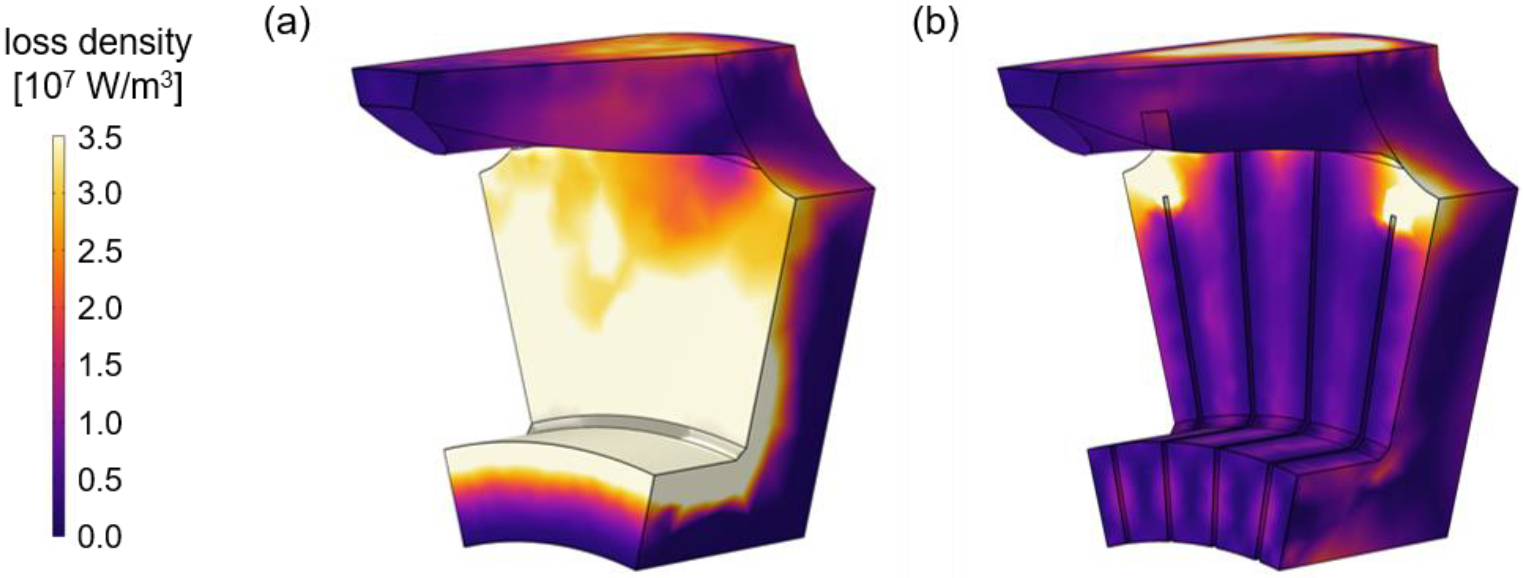
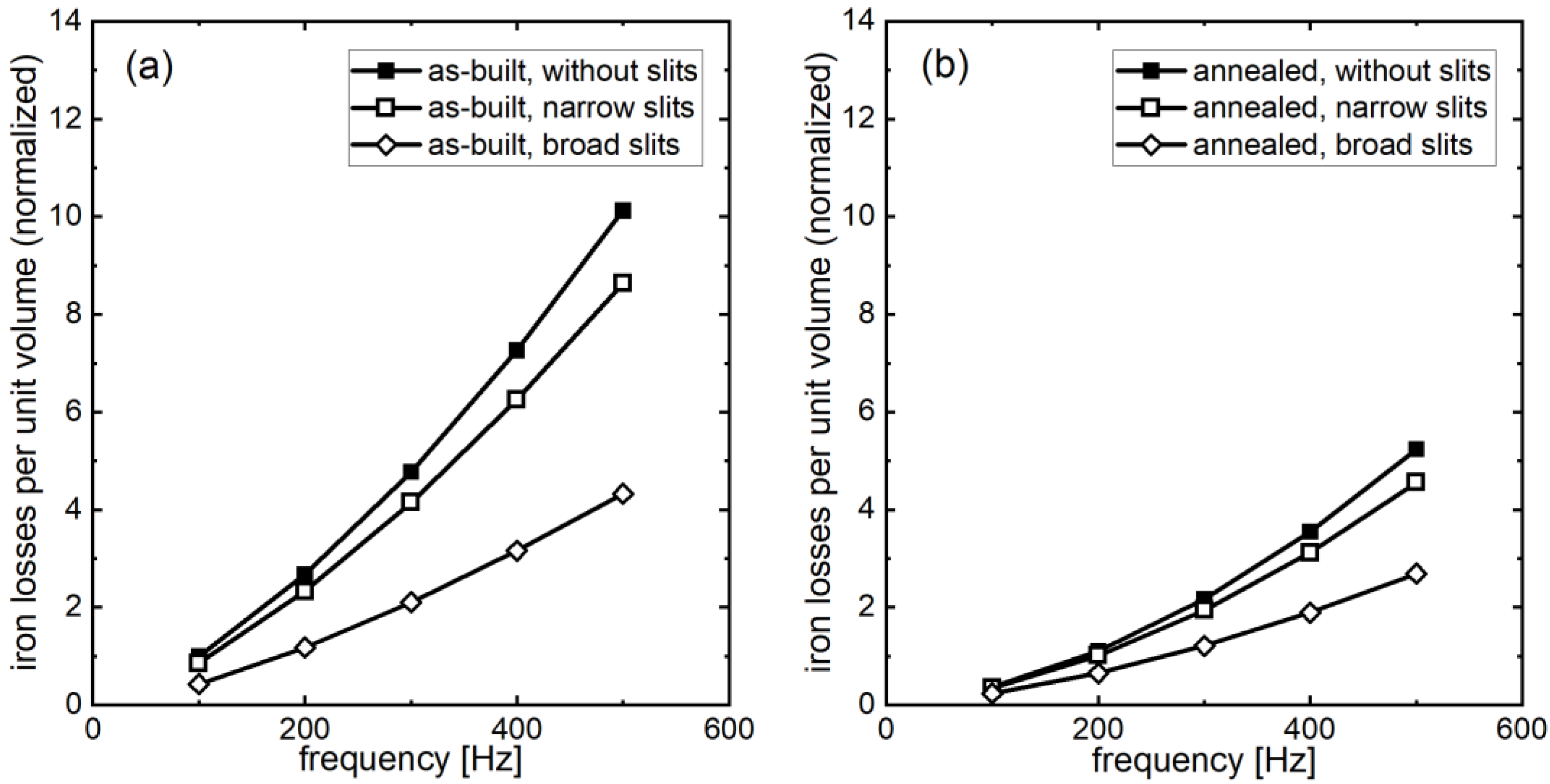
The integration of radially arranged slits leads to spatially lower eddy currents and thus to a lower proportion of eddy currents in the total losses. Therefore, the iron loss is highest in the component without slits. The higher reduction with wider slits is due to the fact that, in this case, there are fewer connection points along the slit, and the slit is relatively continuous, thus not allowing larger eddy currents. The narrow slits, on the other hand, are less continuous due to the manufacturing process, resulting in spatially larger eddy currents due to bridges between the slits. These results are consistent with other studies where the integration of slits oriented along the flux direction in 3%SiFe ring samples also resulted in lower iron losses [
23,
24,
25,
26,
27]. However, the slits in these studies are provided with several bridges due to mechanical stability and therefore not continuous.
The heat treatment reduces internal stresses and inhomogeneities in the microstructure. Furthermore, the grain structure is coarsened leading to a lower density of grain boundaries that generally act as pinning centers for domain walls and thus hinder the magnetization of the material. As a result, the proportion of hysteresis losses in the total losses decreases after the annealing. This effect was also observed by Tiismus et al. [
23,
24]. The reduction of iron losses by heat treatment has a somewhat greater effect on components without or with only narrow slits, since in these cases a larger contiguous defective magnet volume is restored or improved. However, restoration of the microstructure slightly reduces the resistivity of the material, which at high frequencies (outside the operating frequencies of the transverse flux machine) leads to increased eddy current losses and counteracts the lower hysteresis losses. For this reason, the heat treatment carried out is counterproductive from an excitation frequency of just over 1000 Hz, since from this frequency onwards the eddy current losses take on a significantly higher weighting and cancel out the improved hysteresis losses. As seen in
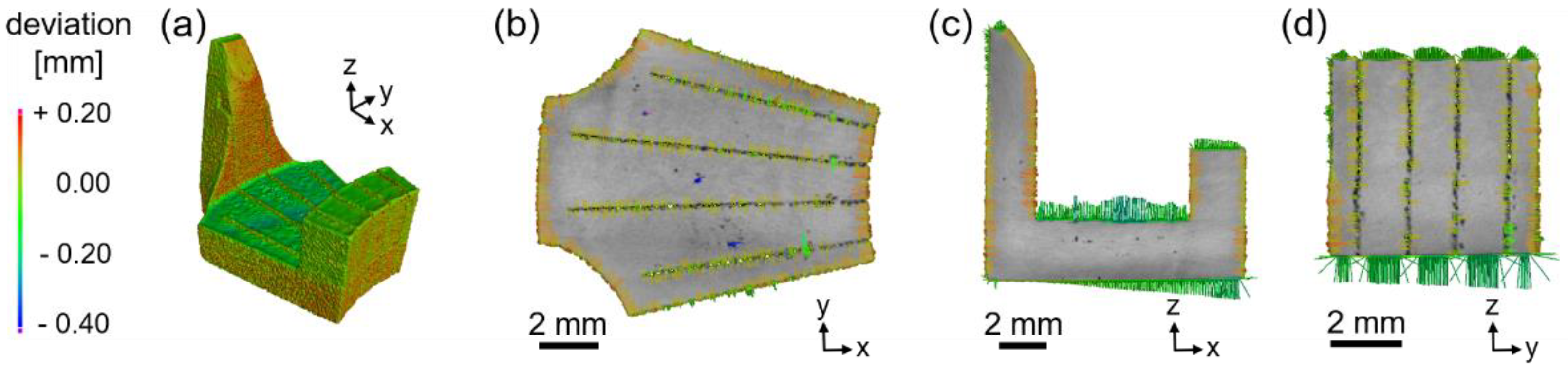
Figure 9, the annealing process of the components has no effect on the thermal stability of the slits, so that an increase of the eddy current losses due to merging of the slits can be ruled out.
The percentage differences between the measurements can largely be attributed to the deviating target polarization, which is significantly lower in the case of the measurement with the commercial device at 0.1 T than in the magnetic response experiment. The reason for this is that, with the magnetic response setup, the correct current for an intended maximum polarization of up to 0.8 T can flow immediately and the measurement can be made within a very short time. The coil system experiences almost no significant heating in this setup. However, in the commercial instrument, it takes time for the correct current to build up to achieve the desired maximum polarization. During this time, the thin coil windings would already heat up too much and destroy the coil system. Therefore, a lower target polarization, at which a non-destructive operation of the coil system was guaranteed, was selected for this measurement method.
Author Contributions
Conceptualization, D.G., T.K. (Thomas Kresse), J.S., G.S., M.S. and N.P.; powder analysis, T.K. (Torsten Kunert); sample manufacturing and heat treatment, J.S. and T.K. (Torsten Kunert); magnetic response measurements, M.L.; microscopy, T.K.(Torsten Kunert); Brockhaus measurements, T.K. (Thomas Kresse); CT analyses, T.K. (Torsten Kunert), CAD conception, M.S.; writing—original draft preparation, T.K. (Thomas Kresse), J.S., D.G. and G.S.; writing—review and editing, D.G., T.K. (Thomas Kresse), G.S. and N.P.; supervision, D.G. and G.S.; project administration, D.G. and N.P.; funding acquisition, D.G. and N.P. All authors have read and agreed to the published version of the manuscript.
Funding
This research was funded by the Ministry of Science, Research and the Arts Baden-Württemberg (MWK) within the scope of the project TopoMAG (grant number: EM-1 TopoMAG) in the framework of ICM (InnovationsCampus Mobilität der Zukunft).
Data Availability Statement
Not applicable.
Acknowledgments
The authors gratefully acknowledge G. Martinek and F. Willburger (both Aalen University) for their support in setting up and performing measurements using the magnetic response method.
Conflicts of Interest
The authors declare no conflict of interest.
References
- Xie, J.; Pan, H.; Fu, H.; Zhang, Z. High Efficiency Warm-cold Rolling Technology of Fe-6.5wt%Si Alloy Sheets. Procedia Eng. 2014, 81, 149–154. [Google Scholar] [CrossRef] [Green Version]
- Goll, D.; Schuller, D.; Martinek, G.; Kunert, T.; Schurr, J.; Sinz, C.; Schubert, T.; Bernthaler, T.; Riegel, H.; Schneider, G. Additive manufacturing of soft magnetic materials and components. Addit. Manuf. 2019, 27, 428–439. [Google Scholar] [CrossRef]
- Wrobel, R.; Mecrow, B. Additive Manufacturing in Construction of Electrical Machines—A Review. In Proceedings of the 2019 IEEE Workshop on Electrical Machines Design, Control and Diagnosis (WEMDCD), Athens, Greece, 22–23 April 2019; pp. 15–22. [Google Scholar]
- Garibaldi, M.; Ashcroft, I.; Simonelli, M.; Hague, R. Metallurgy of high-silicon steel parts produced using Selective Laser Melting. Acta Mater. 2016, 110, 207–216. [Google Scholar] [CrossRef]
- Kallaste, A.; Vaimann, T.; Rassãlkin, A. Additive Design Possibilities of Electrical Machines. In Proceedings of the 2018 IEEE 59th International Scientific Conference on Power and Electrical Engineering of Riga Technical University (RTUCON), Riga, Latvia, 12–13 November 2018. [Google Scholar]
- Lammers, S.; Quattrone, F.; Ponick, B. Additive Manufacturing of a lightweight rotor for a permanent magnet synchronous machine. In Proceedings of the 2016 6th International Electric Drives Production Conference (EDPC), Nuremberg, Germany, 30 November–1 December 2016. [Google Scholar]
- Metsä-Kortelainen, S.; Lindroos, T.; Savolainen, M.; Jokinen, A.; Revuelta, A.; Pasanen, A.; Ruusuvuori, K.; Pippuri, J. Manufacturing of topology optimized soft magnetic core through 3D printing. In Proceedings of the NAFEMS Exploring the Design Freedom of Additive Manufacturing through Simulation, Helsinki, Finland, 22–23 November 2016. [Google Scholar]
- Garibaldi, M.; Gerada, C.; Ashcroft, I.; Hague, R. Free-Form Design of Electrical Machine Rotor Cores for Production Using Additive Manufacturing. J. Mech. Design 2019, 141, 71401. [Google Scholar] [CrossRef]
- Plotkowski, A.; Pries, J.; List, F.; Nandwana, P.; Stump, B.; Carver, K.; Dehoff, R.R. Influence of scan pattern and geometry on the microstructure and soft-magnetic performance of additively manufactured Fe-Si. Addit. Manuf. 2019, 29, 100781. [Google Scholar] [CrossRef]
- Andreiev, A.; Hoyer, K.-P.; Dula, D.; Hengsbach, F.; Haase, M.; Gierse, J.; Zimmer, D.; Tröster, T.; Schaper, M. Soft-magnetic behavior of laser beam melted FeSi3 alloy with graded cross-section. J. Mater. Process. Technol. 2021, 296, 117183. [Google Scholar] [CrossRef]
- Gargalis, L.; Madonna, V.; Giangrande, P.; Rocca, R.; Hardy, M.; Ashcroft, I.; Galea, M.; Hague, R. Additive Manufacturing and Testing of a Soft Magnetic Rotor for a Switched Reluctance Motor. IEEE Access 2020, 8, 206982. [Google Scholar] [CrossRef]
- Zhang, Z.Y.; Jhong, K.J.; Cheng, C.W.; Huang, P.W.; Tsai, M.C.; Lee, W.H. Metal 3D printing of synchronous reluctance motor. In Proceedings of the 2016 IEEE International Conference on Industrial Technology (ICIT), Taipei, Taiwan, 14–17 March 2016. [Google Scholar]
- Kastinger, G. Design of a novel transverse flux machine. In Proceedings of the 2002 International Conference on Electrical Machines (ICEM), Bruges, Belgium, 26–28 August 2002. [Google Scholar]
- Arshad, W.M.; Backstrom, T.; Sadarangani, C. Analytical design and analysis procedure for a transverse flux machine. In Proceedings of the IEEE International Electric Machines and Drives Conference (IEMDC), Cambridge, MA, USA, 17–20 June 2001; pp. 115–121. [Google Scholar]
- Kaiser, B.; Parspour, N. Transverse Flux Machine—A Review. IEEE Access 2022, 10, 18395. [Google Scholar] [CrossRef]
- Wan, Z.; Ahmed, A.; Husain, I.; Muljadi, E. A novel transverse flux machine for vehicle traction applications. In Proceedings of the 2015 IEEE Power & Energy Society General Meeting, Denver, CO, USA, 26–30 July 2015. [Google Scholar]
- Guo, Y.G.; Zhu, J.G.; Watterson, P.A.; Wu, W. Development of a PM transverse flux motor with soft magnetic composite core. IEEE Trans. Energy Convers. 2006, 21, 426–434. [Google Scholar] [CrossRef] [Green Version]
- Shokrollahi, H.; Janghorban, K. Soft magnetic composite materials (SMCs). J. Mater. Process. Technol. 2007, 189, 1–12. [Google Scholar] [CrossRef]
- Keller, M.; Müller, S.; Parspour, N. Design of a permanent magnetic excited transverse flux machine for robotic applications. In Proceedings of the 2016 XXII International Conference on Electrical Machines (ICEM), Lausanne, Switzerland, 4–7 September 2016; pp. 1520–1525. [Google Scholar]
- Keller, M.; Müller, S.; Parspour, N. Design of a transverse flux machine as joint drive for an articulated six-axis robot arm. In Proceedings of the 2016 International Symposium on Power Electronics, Electrical Drives, Automation and Motion (SPEEDAM), Capri, Italy, 22–24 June 2016; pp. 849–854. [Google Scholar]
- Keller, M.; Parspour, N. Experimental identification and validation of model parameters of a permanent magnetic excited transverse flux machine for robotic applications. In Proceedings of the 2017 11th IEEE International Conference on Compatibility, Power Electronics and Power Engineering (CPE-POWERENG), Cadiz, Spain, 4–6 April 2017; pp. 352–357. [Google Scholar]
- Kumar, S.; Czekanski, A. Optimization of parameters for SLS of WC-Co. Rapid Prototyp. J. 2017, 23, 1202. [Google Scholar] [CrossRef]
- Tiismus, H.; Kallaste, A.; Belahcen, A.; Tarraste, M.; Vaimann, T.; Rassãlkin, A.; Asad, B.; Ghahfarokhi, P.S. AC Magnetic Loss Reduction of SLM Processed Fe-Si for Additive Manufacturing of Electrical Machines. Energies 2021, 14, 1241. [Google Scholar] [CrossRef]
- Tiismus, H.; Kallaste, A.; Vaimann, T.; Lind, L.; Virro, I.; Rassãlkin, A.; Dedova, T. Laser Additively Manufactured Magnetic Core Design and Process for Electrical Machine Applications. Energies 2022, 15, 3665. [Google Scholar] [CrossRef]
- Tiismus, H.; Kallaste, A.; Vaimann, T.; Rassãlkin, A. State of the art of additively manufactured electromagnetic materials for topology optimized electrical machines. Addit. Manuf. 2022, 55, 102778. [Google Scholar] [CrossRef]
- Tiismus, H.; Kallaste, A.; Naseer, M.U.; Vaimann, T.; Rassãlkin, A. Design and Performance of Laser Additively Manufactured Core Induction Motor. IEEE Access 2022, 10, 50137–50152. [Google Scholar] [CrossRef]
- Baco-Carles, V.; Huguet, T.; Llibre, J.-F.; Baylac, V.; Pasquet, I.; Tailhades, P. Laser powder bed fusion applied to the manufacture of bulk or structured magnetic cores. J. Mater. Res. Technol. 2022, 18, 599–610. [Google Scholar] [CrossRef]
Figure 1.
Simulated spatial distribution of the electromagnetic loss density per unit volume within a pole of the stator half-shell to be manufactured. (a) Pole without integrated slits. (b) Pole with 4 integrated slits.
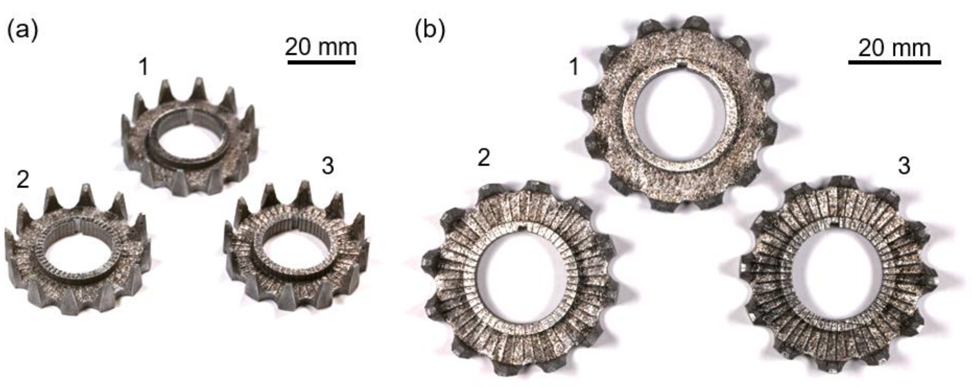
Figure 2.
Additively manufactured stator half-shells made of 99.9% pure iron, (1) without slits, (2) with 150 µm nominal slit width and (3) with 300 µm nominal slit width. (a) Aerial view. (b) Top view.
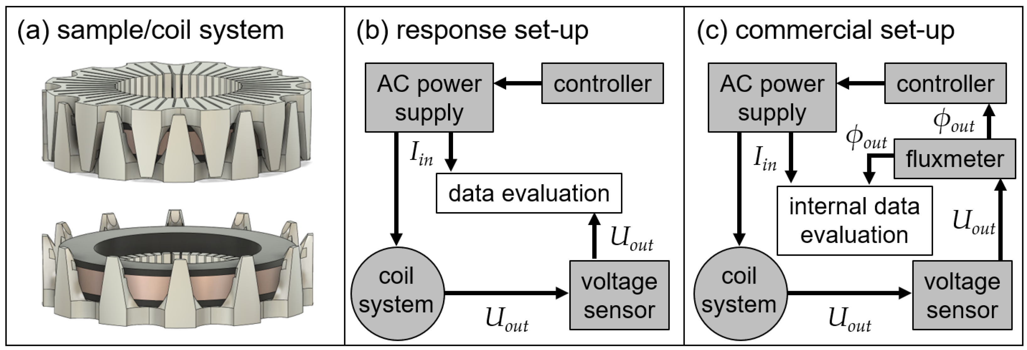
Figure 3.
Schematic of the measurement set-up for the magnetic analysis of the additively manufactured stator half-shells. (a) Arrangement of the sample and the measurement coil system consisting of a black plastic shaft and the wound primary and secondary coil. (b) Schematic of the commercial measuring device MPG 200 D (Dr. Brockhaus Measurements GmbH). (c) Schematic of the self-constructed measurement set-up.
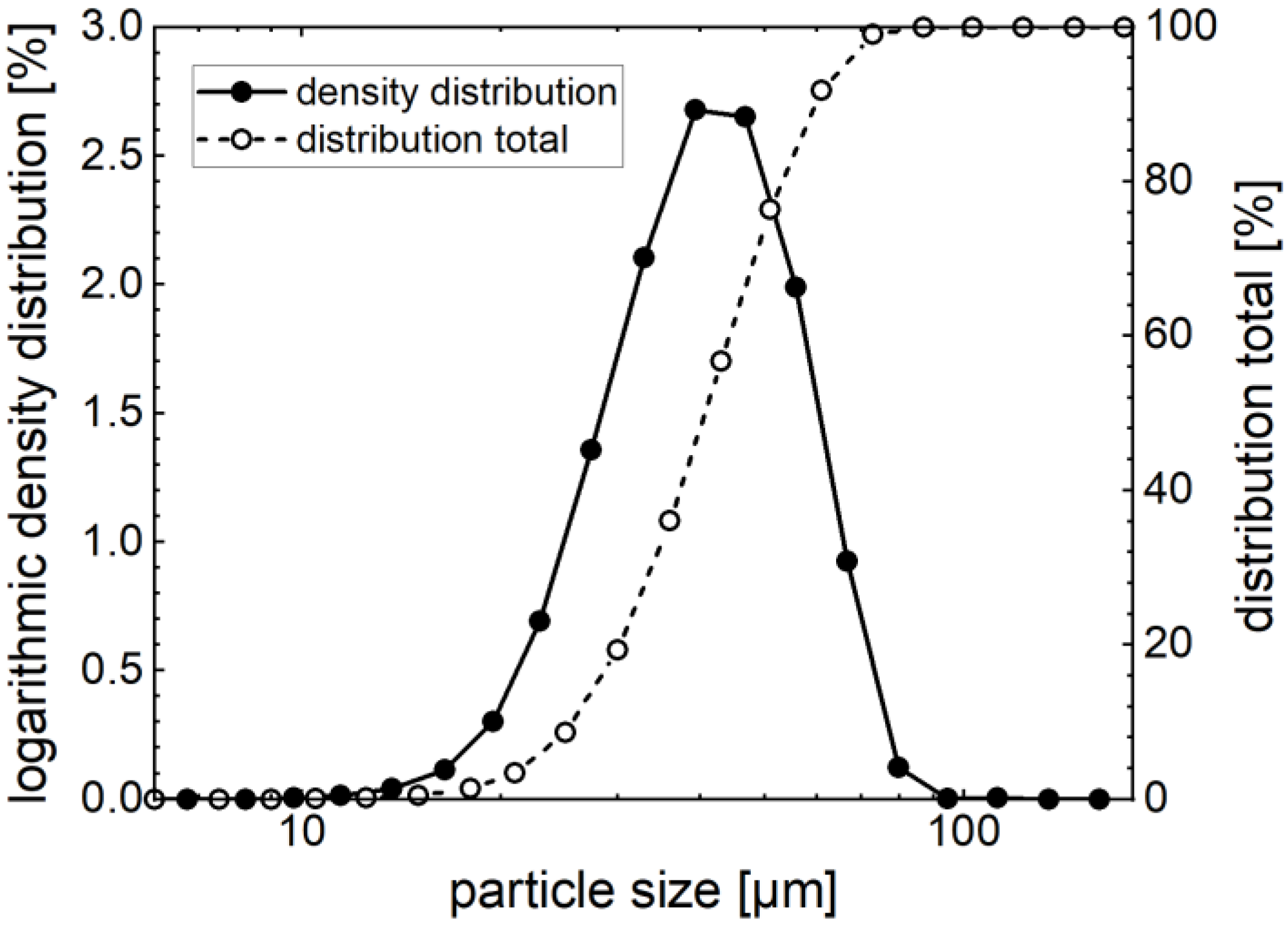
Figure 4.
Volume-specific particle size distribution of the powder used for additive manufacturing (99.9% pure iron) determined by laser diffraction. The median of the particle size distribution is about 41 µm.
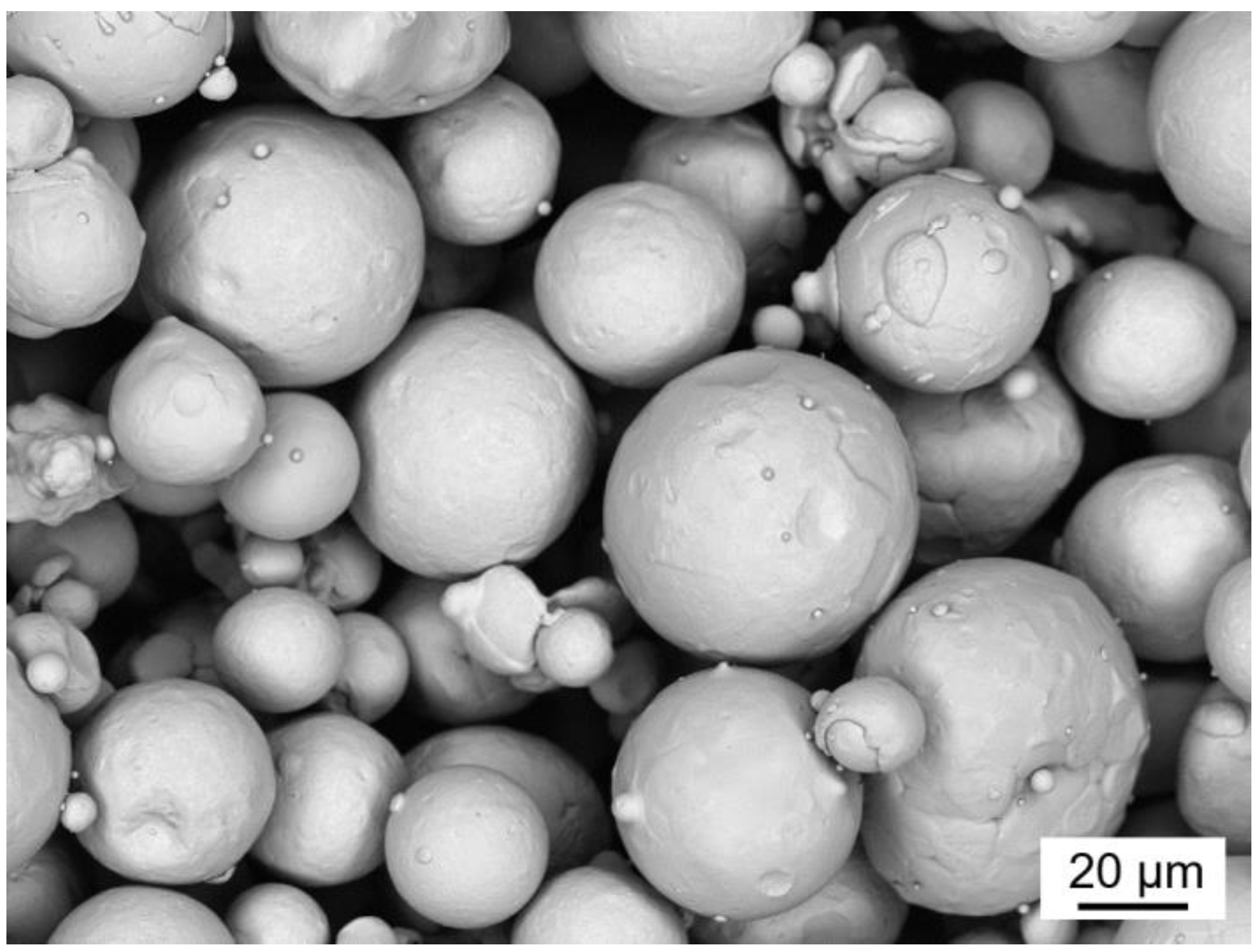
Figure 5.
SEM image of the powder (99.9% pure iron) taken by backscattered electron detector.
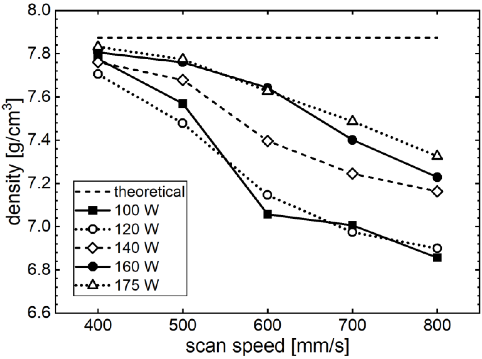
Figure 6.
Density of additively manufactured specimens made of 99.9% pure iron (as-built) as a function of the scanning speed and laser power used.
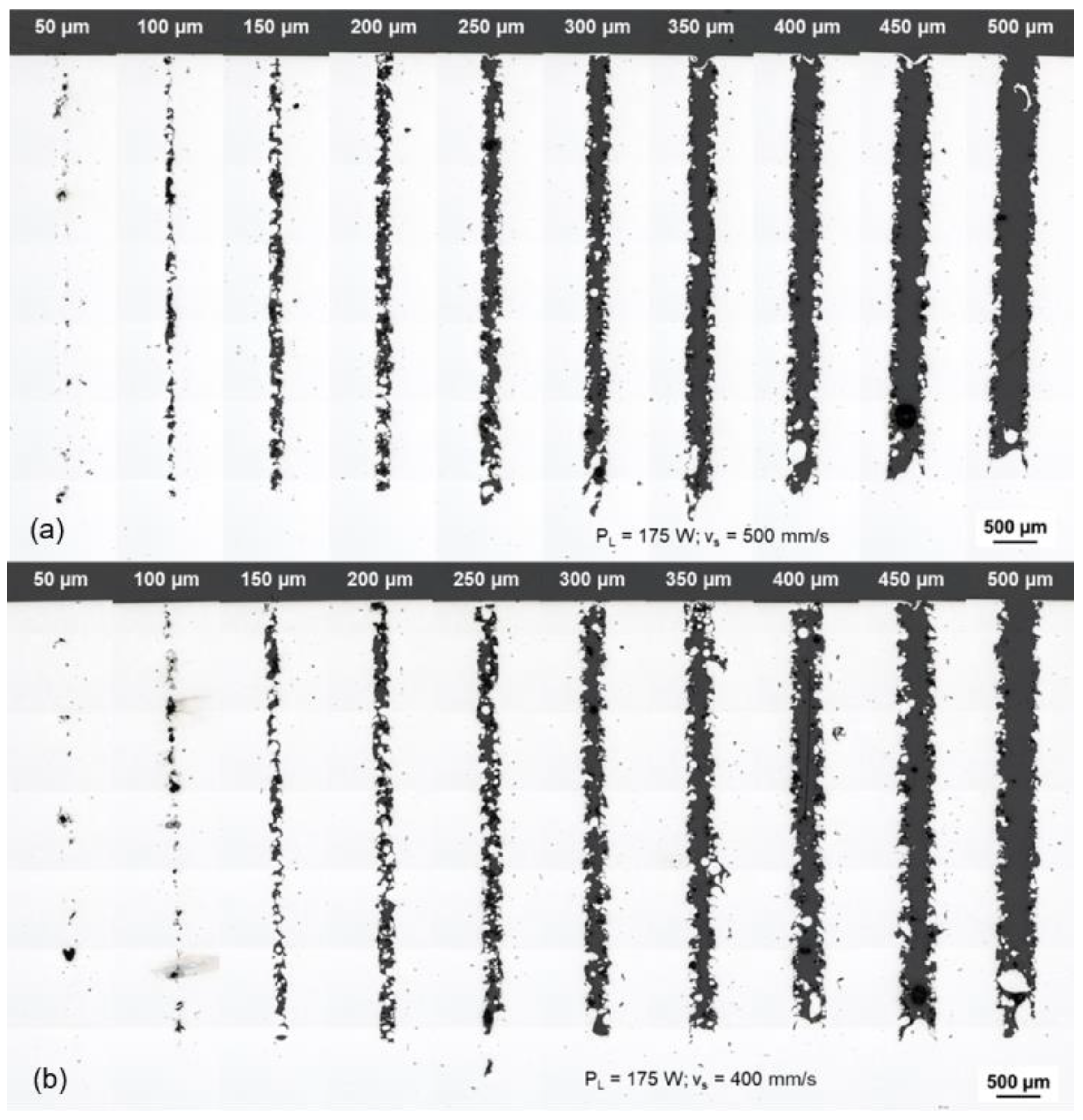
Figure 7.
Cross-sections of the slits of different widths in the additively manufactured 99.9% pure iron specimen taken by optical microscopy at constant laser power (PL = 175 W) and different scanning speeds: (a) vs = 400 mm/s. (b) vs = 500 mm/s.
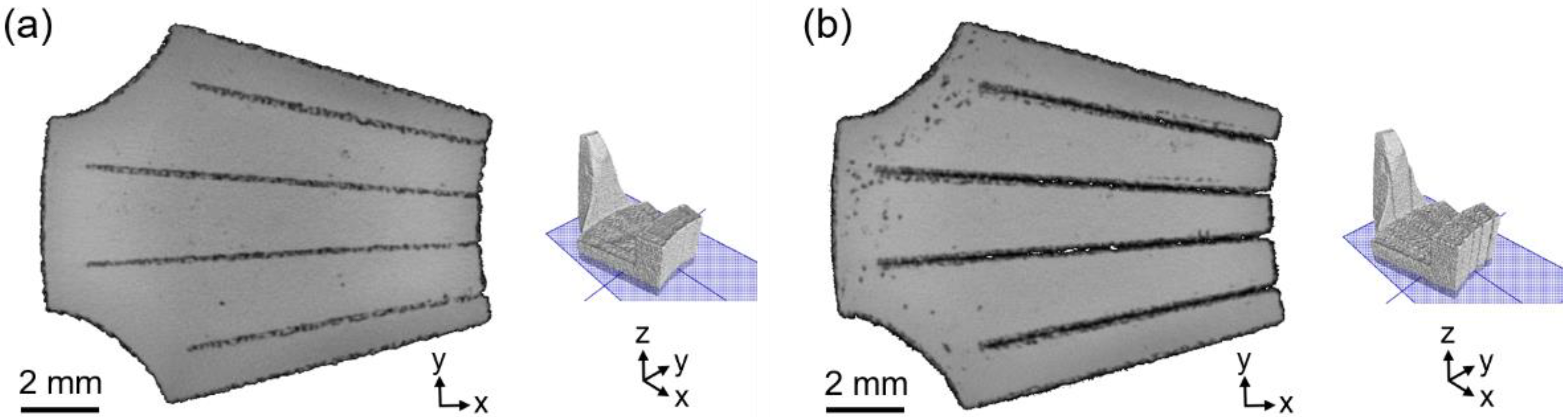
Figure 8.
CT analysis of additively manufactured individual teeth of a modeled stator half-shell made of 99.9% pure iron with integrated as-built slits. (a) Nominal slit width 150 µm. (b) Nominal slit width 300 µm.
Figure 9.
CT analysis of an additively manufactured and heat-treated (6 h @ 1450 °C) single tooth of a modeled stator half-shell made of 99.9% pure iron with integrated slits of 150 µm nominal width each. The colored deflections indicate the deviation of the edge geometries from the modeled template. The colored lines in the right subfigures representing the extent of the deviation in the range of +/-150 µm are shown enlarged for better illustration. (a) Aerial view. (b) View from above (z direction). (c) View from the side (y direction). (d) View from the side (x direction).
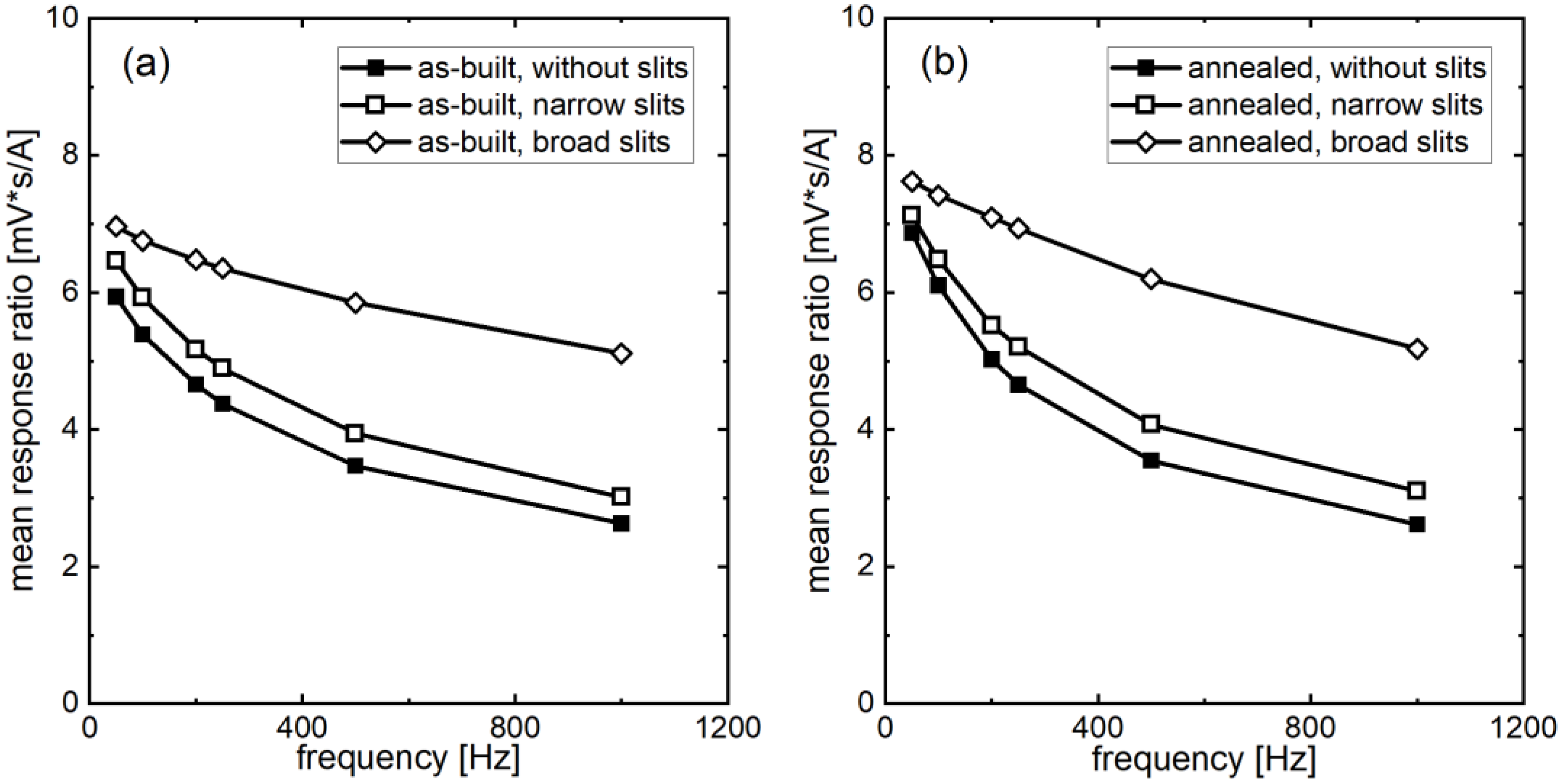
Figure 10.
Mean response ratio of the 99.9% pure iron stator half-shells investigated using the magnetic response setup as a function of the frequency used. The response ratio is the induced sensor voltage Uout of the secondary coil divided by the excitation current Iin of the primary coil and the applied frequency f. (a) As-built state. (b) Annealed state (1150 °C; 6 h).
Figure 11.
Normalized iron losses of the transverse flux components made of 99.9% pure iron at 0.1 T peak polarization, measured with the commercial measuring instrument MPG 200 D (Dr. Brockhaus Measurements GmbH). The reference value (=1) is the iron losses of the as-built compact component at 100 Hz. (a) As-built state. (b) Annealed state (1150 °C; 6 h).
| Publisher’s Note: MDPI stays neutral with regard to jurisdictional claims in published maps and institutional affiliations. |
© 2022 by the authors. Licensee MDPI, Basel, Switzerland. This article is an open access article distributed under the terms and conditions of the Creative Commons Attribution (CC BY) license (https://creativecommons.org/licenses/by/4.0/).


 ,
, 


