Article

Optimization of Heavy Reduction Process on Continuous-Casting Bloom

1
National Engineering and Research Center for Continuous Casting Technology, Central Iron and Steel Research Institute, Beijing 100081, China
2
School of Metallurgical and Ecological Engineering, University of Science and Technology Beijing, Beijing 100083, China
3
Department of Chemistry and Chemical Engineering, Lvliang University, Lvliang 033001, China
4
Material Digital R&D Center, China Iron & Steel Research Institute Group, Beijing 100081, China
*
Authors to whom correspondence should be addressed.
Metals 2022, 12(11), 1873; https://doi.org/10.3390/met12111873
Submission received: 30 September 2022 / Revised: 28 October 2022 / Accepted: 29 October 2022 / Published: 2 November 2022
(This article belongs to the Special Issue Numerical Simulation of Solidification Processes)

Abstract

:
Heavy reduction (HR) is an effective technique to control V segregation in continuous casting bloom, but the effect of segregation improvement is limited by the parameters such as reduction position and reduction amounts. In order to improve the macrosegregation of bloom, numerical simulation and plant experiments are adopted in this research. A heat transfer model and a reduction model with comprehensive thermo-physical parameters were established. The two models were verified by comparing the measured surface temperature and the theoretical strain at the solidification front. It is determined that the position of the HR of the bearing steel bloom is 20.82 m~24.97 m from the meniscus, and the solid fraction in the center of the bloom is 0.6~1. The total reduction of the HR is set to 30 mm, and the reduction of each roller in the reduction range is set to 4 mm, 5 mm, 9 mm, 7 mm, and 5 mm, respectively, to prevent the formation of internal cracks. Plant trials were conducted to verify the effect of the optimized HR. The results show that the carbon segregation degree on the V channel and non-channel of the bloom decreases from 1.2 to 1.16 and increases from 0.93 to 0.95, respectively, and the central carbon segregation degree decreases from 1.17 to 1.15. Meanwhile, the internal crack was not found in the bloom.

1. Introduction

Bearing steel is the basic steel of the advanced manufacturing industry. With the transformation and upgrading of the manufacturing industry, higher requirements are put forward for the quality of bearing steel [1]. Bearing steel is mostly produced by bloom continuous casting. Due to its high carbon content, macrosegregation occurs easily in the continuous casting process [2,3]. However, is difficult to eliminate or greatly improve segregation in subsequent rolling and heat treatment [4]. Therefore, macrosegregation has greatly affected the quality of products.
Low superheat pouring technology [5], electromagnetic stirring technology [6,7], and billet reduction technology [8,9] are considered effective in improving the macrosegregation of the billet. Low superheat casting technology can improve the equiaxed crystal rate of the billet, but whether it can reduce the equiaxed crystal size has not been determined. In addition, the size of equiaxed grains is directly related to the point segregation, and the relationship between superheat and the size, shape, distribution, and solute enrichment of point segregation in continuous casting billet is the theoretical basis for formulating control measures, but there are few reports [10]. Therefore, it is still difficult to improve the macroscopic point segregation by adjusting the superheat.
Oh K S et al.studied the effect of different electromagnetic stirring modes on V segregation in 250 mm × 300 mm bloom, and the results showed that S-EMS had the best effect on regulating V segregation [11]. According to the formation theory of V segregation, the effects of M-EMS and S-EMS on segregation are embodied in solidification structure and molten steel fluidity. The conclusions of different scholars are contradictory as to whether or not it can regulate the size and area ratio of V segregation [10].
In the above technologies, billet reduction technology includes mechanical soft/heavy reduction [12,13,14,15], thermal soft reduction [16,17,18,19,20,21], and hot core heavy reduction technology. Among them, the hot core reduction technology is mainly used for welding the shrinkage of the casting blank, the hot reduction technology is to rely on the end surface cooling to achieve a rapid temperature drop of the billet surface corresponding to the center of the billet, thereby compensating for the solidification shrinkage of the central area and inhibiting the flow of the enriched liquid to the center of the billet [17]. Mechanical soft reduction is generally implemented in the solid phase ratio of 0.6~0.8 range, the amount of reduction is generally not more than 10 mm [22].
With the improvement and upgrading of the continuous casting machine, the section of the billet is becoming larger and larger. The single hot reduction technology and soft reduction technology obviously cannot meet the requirements of improving the macrosegregation of the bloom. Heavy reduction (HR) technology of the final Solidifying End is considered to be an effective means to improve the macrosegregation of bloom [23]. Macrosegregation mainly includes central segregation and V segregation. The formation of central segregation can be attributed to the flow of enriched molten steel in the two-phase region during the final solidification process [24,25,26,27], which can be caused by many factors, such as bulging, roll offset, solidification and heat shrinkage during continuous casting. Many scholars have proposed mechanical soft or heavy reduction [12,13,14,15] and thermal soft reduction [16,17,18,19,20] to improve central segregation and achieved remarkable results.
Different scholars have different views on the causes of V segregation. Tomono believes that V segregation is due to the fact that the enriched liquid between the equiaxed crystals is sucked in and flows downwards, and that the enriched liquid accumulates along certain planes as the accumulated equiaxed crystals forcefully move toward the center of the bloom [28]. Abbott [29] believed that V segregation is caused by the erosion and thermal tearing of the solid by the flowing enrichment liquid. Li et al. believe that V segregation is caused by solidification shrinkage tearing cracks in the equiaxed dendritic network [30]. Therefore, the reasons for the formation of bloom V segregation remain to be further explored, from the principle of control V segregation has not yet formed a unified view.
At present, the research on reducing spot segregation and V segregation by roller soft reduction has been widely reported [22,31,32]. However, the casting machine, steel, casting speed, and production environment have a certain degree of difference, so the use of HR control V segregation still needs a separate analysis. In this paper, the 380 mm × 450 mm bearing steel bloom was studied. This production line is newly built, the initial production of bloom specifications 380 mm × 450 mm, and there are problems such as macrosegregation in the bloom. In order to determine the solid phase rate at the solidification end of the bloom, a solidification heat transfer model was established. Then a reasonable reduction interval was determined. At the same time, a series of reduction parameters was proposed based on the thermal-mechanical coupling model, which theoretically controlled the generation of internal cracks. Finally, plant experiments were carried out to verify the improvement effect of the optimized HR parameters on V segregation.

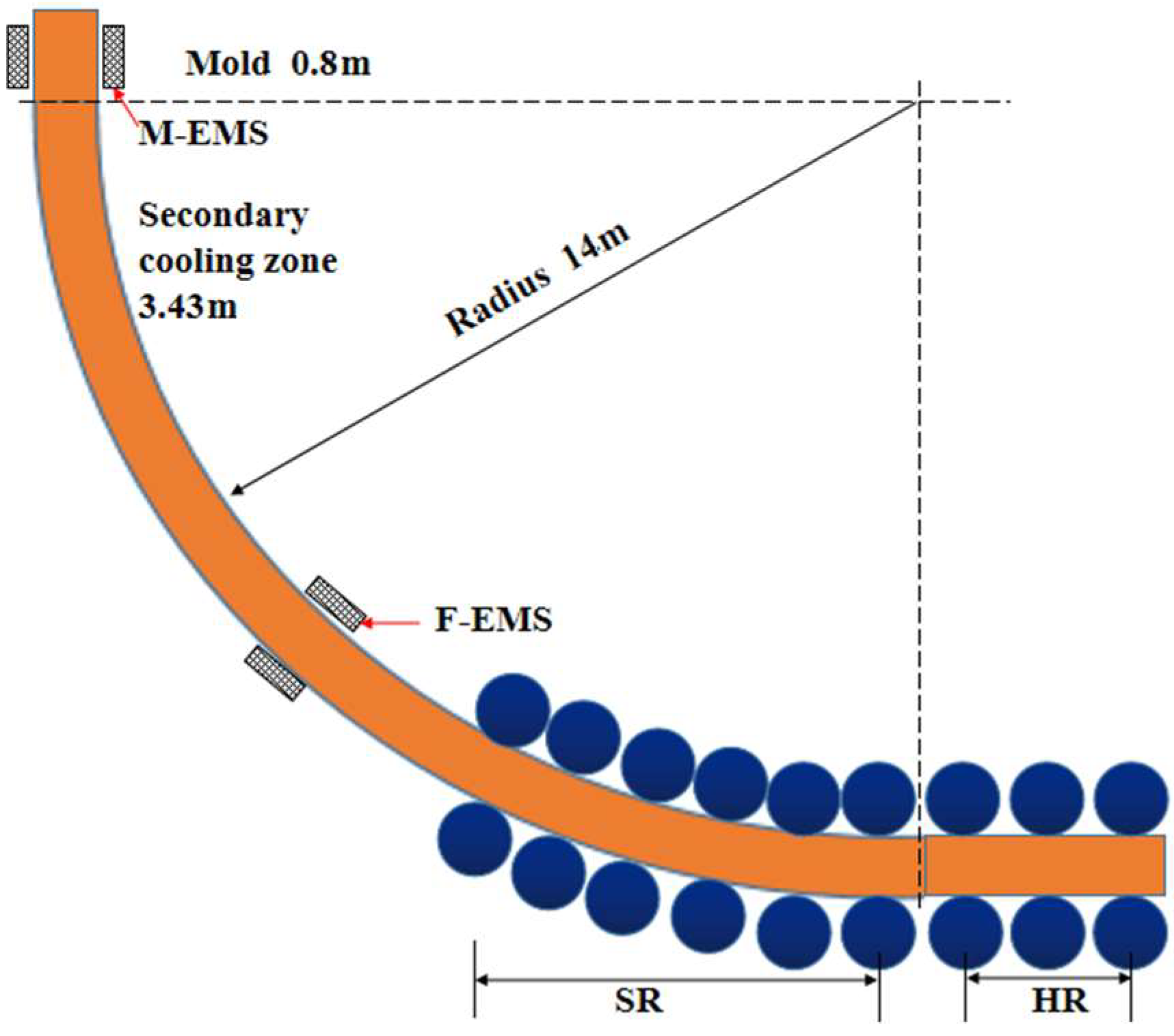
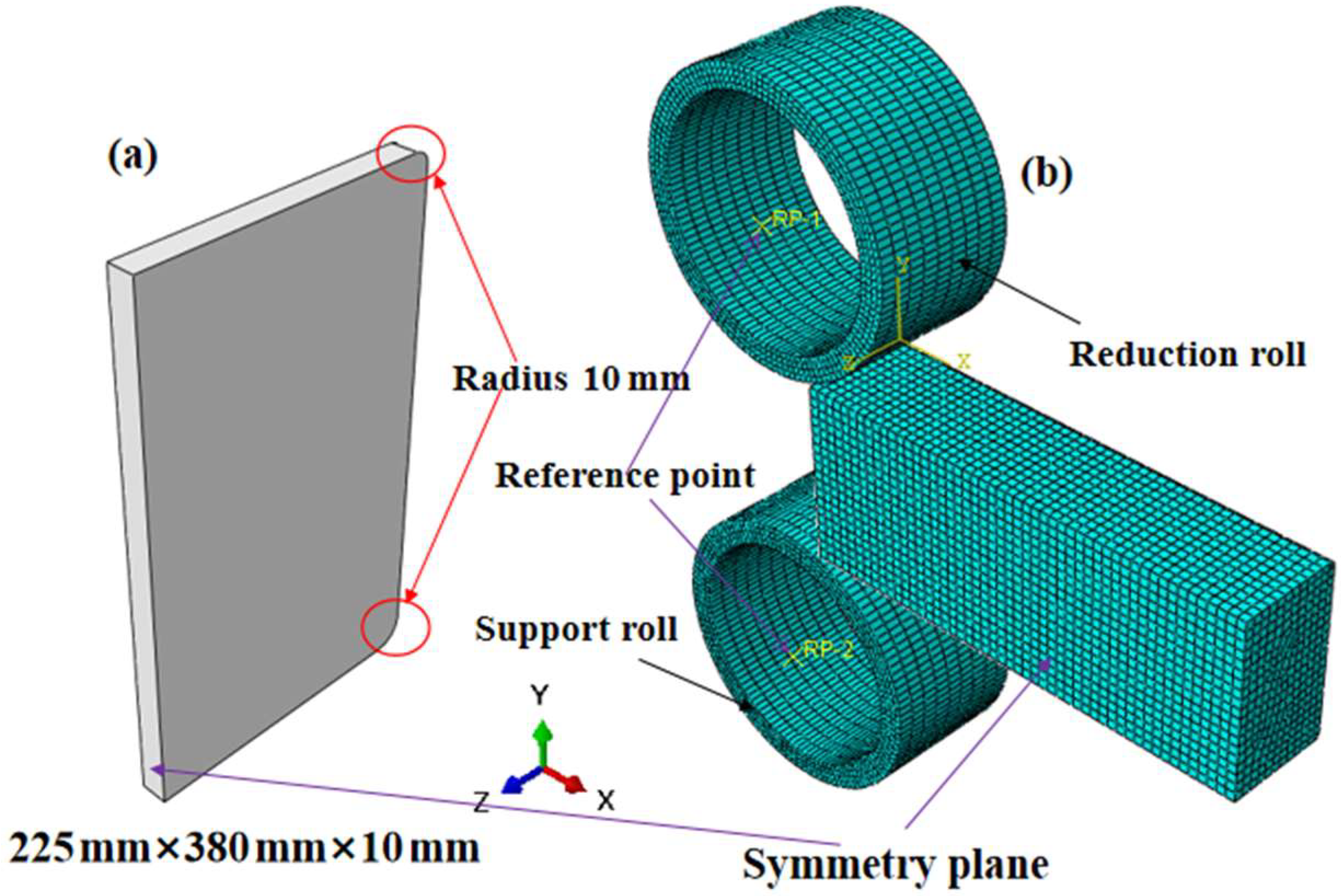
2. Model Description

A circular-arc caster with a curved mold was studied. The caster has five strands and mainly produces the bloom with a section size of 250 mm × 250 mm and 380 mm × 450 mm. Its arc radius is 14 m. The schematic diagram of the bloom caster is shown in Figure 1. The effective lengths of the mold and the secondary cooling zone are 0.8 m and 3.43 m, respectively. Mold electromagnetic stirring (M-EMS), final electromagnetic stirring (F-EMS), and a casting and rolling system of solidification end are applied to improve the quality of the bloom. In the secondary cooling zone, air-mist nozzles are used to ensure uniform cooling. The distance from the roll-casting system of the solidification end to the meniscus is 18.67 m~27.17 m, mainly including six pairs of soft reduction(SR) rollers and three pairs of heavy reduction rollers. Among them, the first six pairs of reduction rollers are soft reduction equipment, which is installed in the arc section. The last three pairs of reduction rollers are heavy reduction equipment, which is installed in the horizontal section. The diameter of all reduction rollers is 500 mm. In the solidification end, HR is applied to improve the inner quality of the bloom, while its technical parameters are underdetermined.

2.1. Model Establishment

A slice-moving method was applied to the heat transfer model. Figure 2a shows the coordinate system and geometric model of the slice. To simplify the calculation, the geometric model adopted half of the transverse section of the bloom with a thickness of 10 mm, namely with a dimension of 225 mm × 380 mm × 10 mm. The geometric model also considered the round corner according to the final bloom size. The radius of the round corner was 10 mm. During the simulation, it was assumed the slice moved from the mold to the secondary cooling zone and the air-cooling zone. Figure 2b shows the reduction finite element of the bloom, including the reduction roller, support roller, and bloom. The reduction roller and support roller are rigid materials, while the bloom is an elastic material. Considering the symmetry of the width direction of the bloom, the geometric size of the bloom in the model is 225 mm × 380 mm × 1000 mm. The radius, thickness, and length of the two rollers are 300 mm, 50 mm, and 300 mm. The total number of model grids is 72,000.

2.1.1. Assumption

Under the premise of ensuring calculation accuracy, the following assumptions are made for the heat transfer model and the reduction model, respectively:
(1)
The heat transfer was neglected in the casting direction and the meniscus.
(2)
The convective heat transfer was equivalent to conductive heat transfer.
(3)
Deformation at the solidification end of the bloom conforms to the small deformation theory.
(4)
The influence of ferrostatic pressure and bending straightening force in casting direction on bloom deformation was ignored.
(5)
The high-temperature creep of the bloom is neglected and the reduction process is steady-state process.

2.1.2. Governing Equation

Based on the above assumptions, a two-dimensional unsteady state heat transfer equation was expressed as follows. The equivalent specific heat method is used to express the effect of solidification latent heat on the solidification process, referring to Reference [22].
ρ c T t = x ( k T x ) + y ( k T y )
where, ρ is density, kg/m2; c is the specific heat capacity, J/(kg·°C); k is the thermal conductivity, w/(m·°C); T is temperature, °C; and x and y are the distance in the width direction of the bloom transverse section, m.
The total deformation of bloom during reduction consists of thermal deformation, elastic deformation increment, and plastic deformation increment.
d ε = [ α ] d T + [ D e ] 2 d σ + dk φ σ
where, dε is the total deformation; [α] is thermal expansion coefficient matrix; T is temperature, °C; [ D e ] is an elastic matrix, σ is stress, Pa; k is a constant, φ is Mises yield function.

2.1.3. Boundary Conditions and Initial Condition

(1)
Initial condition
For the solidification heat transfer process, the casting temperature is the same as the temperature of the molten steel in the tundish, and the meniscus in the mold is the initial time. For the reduction process, the thermally calculated temperature field is loaded into the initial conditions of the reduction model. The casting speed is 0.45 m/min, the roller speed is 0.025 rad/s, and the initial temperature of the roller is 300 °C.
(2)
Boundary Conditions
The boundary conditions of heat transfer analysis refer to Reference [22] to set the mold zone, secondary cooling zone, and air cooling zone respectively. The Coulomb friction model is used to treat the interface friction in the three-dimensional bloom reduction model, and the friction coefficient is set to 0.33. The heat transfer coefficient between the reduction roller and the bloom during the continuous casting process is 8000 W/(m2·°C). The plastic deformation energy of the reduction process is converted into heat energy, and the transformation coefficient of plastic energy is 0.9. The convective heat transfer coefficient between bloom and environment is 165 W/(m2·°C).

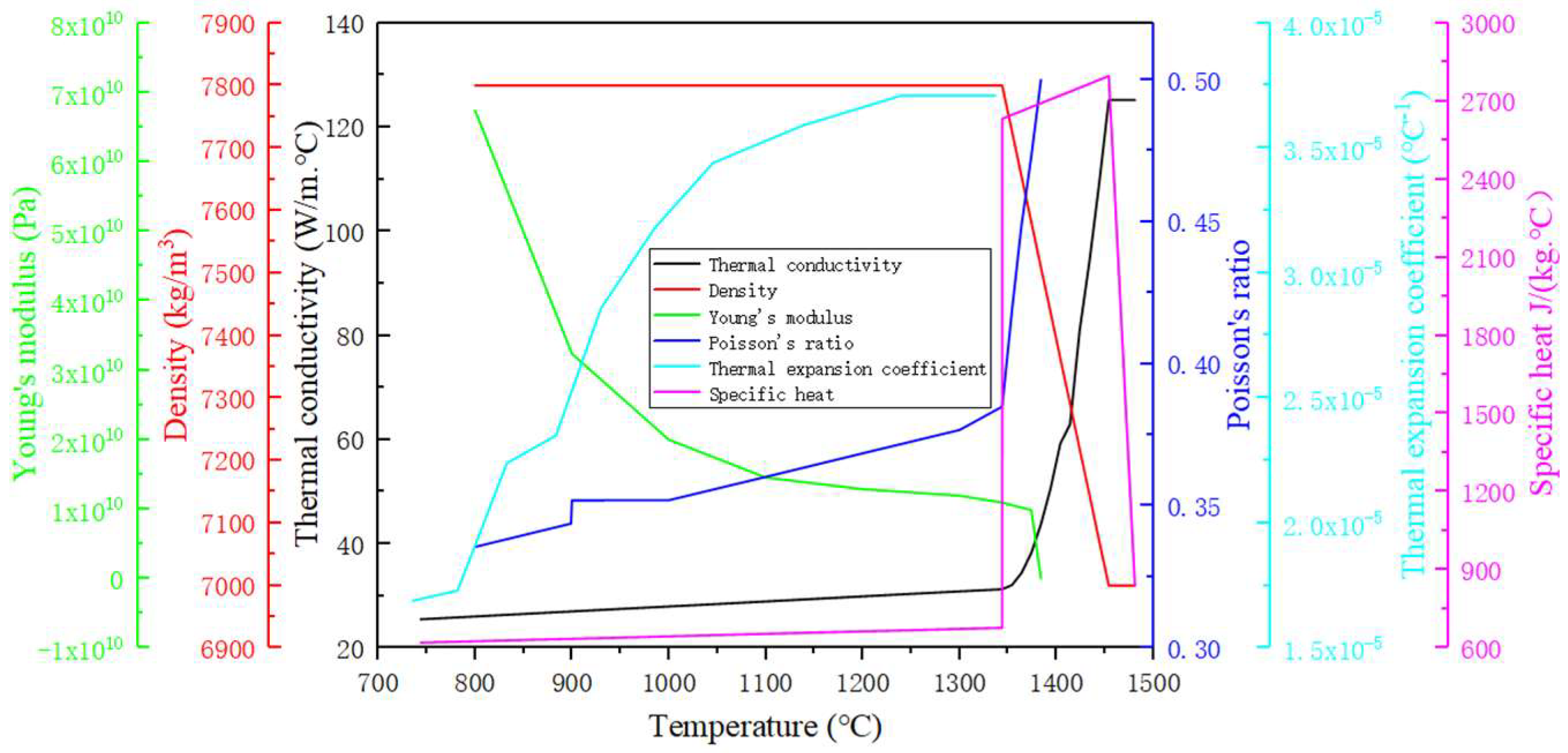
2.2. Material Properties

GCR15-bearing steel was studied and its chemical composition is given in Table 1. The variations of thermal conductivity, density, specific heat, young’s modulus, poisson’s ratio, and thermal expansion coefficient with temperature were calculated using the thermodynamic database from JMatPro software (Material Digital R&D Center, Beijing, China), as shown in Figure 3. The physical parameters of bearing steel are related to temperature. Plastic strain parameters refer to Reference [33], which are related to deformation temperature and strain rate. The elastic modulus decreases with increasing temperature, and the value in the liquid region is infinitely close to 0, while the Poisson‘s ratio is 0.5 at the liquidus.

3. Results and Discussion

3.1. Model Validation

The main casting parameters of GCR15-bearing steel are shown in Table 2. As shown in Figure 4, it is the distribution of center temperature and surface temperature of 380 mm × 450 mm bearing steel bloom. In the range of 14.1 m~17 m from the meniscus, the infrared thermometer is used to measure the temperature of the bloom surface in actual production. Table 3 shows the numerical simulation values and measured values of four temperature measuring points. According to the data in the table, the maximum error is 1.16%, which is less than 5%. It shows that the solidification heat transfer model in this study can accurately simulate the solidification process of the bloom.

3.2. Location of HR

The HR technology at the solidification end can inhibit the thermal expansion and volume shrinkage of the bloom, and reduce its suction effect on the concentrated solute in the center of the bloom. Choosing a reasonable reduction location is the key to improving the segregation of bloom under HR. Kojima S et al. [34] reduced the central solid fraction to between 0.8 and 1.0 of the bloom, the spot segregation on the cross-section of the bloom was greatly reduced, and there was no obvious V segregation on the longitudinal section. Nabeshima et al. [35] performed continuous reduction with a compression ratio of 0.92 on a 400 mm × 560 mm bloom at a central solid fraction of 0.87, and the V segregation effect was significantly improved. In fact, the reasonable reduction position to improve central segregation and V segregation is different. Some experts believe that the center solid fraction of the reasonable reduction range for improving the center segregation is 0.3–0.8 [34,35], but some scholars believe that the center solid fraction range of the reasonable reduction position is 0.6–0.8 [22,36]. The central solid fraction at the appropriate reduction position for improving V segregation should be higher than 0.8 [34,35]. Therefore, in this study, the reasonable range of central solid fraction is 0.6~1 to improve the macrosegregation of bloom by using the technology of HR at the end of solidification.
In the production process, the solidification end point of the bloom is mainly affected by the casting speed, cooling water, and superheat. Among them, the production line adopts intelligent water distribution, and the cooling intensity is a fixed value. Therefore, in this study, the influence of cooling water change on the solidification end point of bloom is ignored, and only the influence of casting speed and superheat change is considered. Figure 5 shows the effect of casting speed on the solidification end when the superheat is 26 °C. As can be seen from the figure, the black line, red line, and green line represent the changing trend of the center temperature of the billet with the position when the casting speed is 0.44 m/min, 0.45 m/min, and 0.46 m/min, respectively. It can be seen from the figure that when the casting speed is 0.45 m/min, the solidification end point of 380 mm × 450 mm bearing steel bloom is 23.13 m away from the meniscus. When the casting speed decreases by 0.01 m/min, the solidification end point moves 0.51 m. Therefore, when the casting speed changes in the range of 0.44~0.46 m/min, the solidification end point of 380 mm × 450 mm bearing steel bloom changes in the range of 22.62~23.64 m from the meniscus.
As shown in Figure 6, the effect of different superheats on the center temperature of 380 mm × 450 mm bearing steel bloom was studied when the casting speed was 0.45 m/min. As can be seen from the figure, the black line, red line, and blue line represent the superheat of 11 °C, 26 °C, and 41 °C, billet center temperatures change the trend with the position. It can be seen from the figure that the superheat mainly affects the liquidus disappearance position and the solidification end point during the solidification process of the bloom. When the superheat is 11 °C, 26 °C, and 41 °C respectively, the liquids disappearance position of 380 mm × 450 mm bearing steel bloom is 5.98 m, 6.48 m, and 6.98 m respectively from the meniscus, and the solidification end point is 22.81 m, 23.13 m, and 23.45 m respectively from the meniscus. In other words, for every 15 °C change in the superheat, the distance from the liquidus of the bearing steel bloom to the meniscus changes by 0.5 m, and the solidification end point changes by 0.32 m. When the superheat changes in the range of 11~41 °C, the disappearance position of the liquidus of the 380 mm × 450 mm bearing steel bloom moves within the range of 5.98~6.98 m from the meniscus, and the solidification end point fluctuates within the range of 22.81~23.45 m from the meniscus.
Comparing Figure 5 and Figure 6, when the casting speed is 0.45 m/min and the superheat is 26 °C, the effect of casting speed on the solidification end point of 380 mm × 450 mm bearing steel bloom is much greater than that of superheat. It can be seen from Figure 1 that the arrangement range of the end casting roller 1 #~7 # of the bloom continuous caster is 18.67~27.17 m. As shown in Figure 7, the curve of center temperature and solid fraction of 380 mm × 450 mm bearing steel bloom with casting speed of 0.45 m/min and average superheat of 26 °C. It can be seen from the figure that the central solid fraction of the bloom at the 1 #~6 # roller is 0.45, 0.51, 0.6, 0.71, 0.9, and 1, respectively, and the central solid fraction of the bloom at the 7 #~9 # roller is 1. Combined with the roller arrangement and reasonable reduction range, the action position of HR is determined to be 3 #~6 # roller. Considering that the influence of casting speed and superheat on the solidification end point of the bloom can be up to 0.51 m, and that the local high-temperature phase or shrinkage cavity may aggravate the central segregation of the bloom, the actual reduction range is extended back to the 7 #. Therefore, the HR range at the solidification end of 380 mm × 450 mm bearing steel bloom with a casting speed of 0.45 m/min and an average superheat of 26 °C is 20.82 m~24.97 m from the meniscus, and the corresponding reduction roller is 3 #~7 #.

3.3. Reduction Amounts of HR

During the reduction process, plastic strain may occur at the solidification front. When the stress and strain exceed the critical value, the bloom solidification front forms an internal crack, which deteriorates the quality of the bloom. Therefore, the amount of reduction depends on the high-temperature critical stress and strain value of the bloom at the reduction position. There are critical strain hypothesis, critical stress hypothesis, and critical time hypothesis to measure whether the solidification front of the bloom can produce cracks [37]. In this study, the critical strain of the solidification front was used as the criterion to determine the reduction amount. Generally, the solidification front is defined as the region between the solidus and liquidus. Some scholars [38,39,40] divided the solidification front into three parts according to the temperature, as shown in Figure 8 [41], which are the liquid phase region (ZST ≤ T ≤ Tl), the filling region (LIT ≤ T ≤ ZST), and the crack high-incidence region (ZDT ≤ T ≤ LIT). Where Tl is the liquidus of liquid steel, and the liquidus of bearing steel in this study is 1454 °C; ZST, LIT, and ZDT are called zero strength temperature, viscosity temperature, and zero ductility temperature, respectively, and their corresponding solid fractions are 0.8, 0.9, and 1, respectively [42].
When the cumulative strain in the temperature brittleness interval exceeds the critical strain, the solidification front will produce internal cracks [41]. The molten steel in the liquid phase zone has good fluidity. The filling zone can be filled with molten steel in time [42]. Therefore, the range from ZDT to LIT in the solidification front is prone to cracks. In this paper, the temperature range of the high crack area of the bearing steel is from the solidus to 1355 °C. Cai [43] studied the critical strain solution criterion for internal cracks in the solidification front, as shown in Figure 9 [44], which is the relationship between carbon equivalent and critical strain.
C e q = [ C ] + 0.02 [ M n ] + 0.04 [ N i ] 0.1 [ S i ] 0.04 [ C r ] 0.1 [ M o ]
According to Formula (3), the carbon equivalent of GCR15 bearing steel is 0.65%, and w[Mn] ⁄ w[s] = 175, so the critical strain of GCR15 steel at the solidification front is 0.4%. As long as the reduction amount causes the single or cumulative strain of the bearing steel bloom to be less than 0.4% in the solidus to 1355 temperature range, the solidification front will not crack.
According to the solidification heat transfer model, the temperature fields of the bloom cross-section corresponding to the central solid fraction of 0.6, 0.71, and 0.9 are obtained respectively, as shown in Figure 10. The area covered between the white semicircles (solidus to 1355 °C) in the diagram is the high crack area of the bloom at this reduction position. The high-incidence area of cracks is regarded as a concentric circle. When the central solid fraction of the bearing steel bloom is 0.60, 0.71 and 0.9, the corresponding ranges of the high-incidence area of cracks are 41 mm ≤ r ≤ 55 mm, 31.6 mm ≤ r ≤ 44.6 mm, and 0 ≤ r ≤ 19 mm, respectively. In short, when different reduction amounts are applied to the positions of 3 #~5 #, the plastic strain in the high crack area is lower than the critical strain value, which is a reasonable parameter.
Zhong [45] studied the effect of different total reduction amounts on the center segregation of 350 mm × 470 mm bearing steel bloom. The results show that after applying the total reduction of 4.5 mm, 6 mm, 9 mm, and 13 mm respectively, the total reduction of 6 mm is the most obvious to improve the center segregation, while the total reduction of 9 mm is the second. Wu et al. [44] studied the effect of reduction on macrosegregation of high carbon steel bloom, and the results showed that for 400 mm thickness bloom, the reasonable total reduction was 20~30 mm. The thickness of the bearing steel bloom in this study is 380 mm. According to the research conclusions of Wu et al., the total reduction was set to 30 mm.
Isobe et al. [46] found that the reasonable reduction rate for improving macrosegregation is 1.8~6.6 mm/m or 0.72~4.7 mm/m, and the reduction efficiency is 7~34%. In this study, the roller spacing between 3 #~7 # reduction rollers in the reduction zone of bearing steel bloom is the distance from 3 # to 4 # roller is 900 mm, the distance from 4 # to 5 # roller is 1200 mm, the distance from 5 # to 6 # roller is 900 mm, and the distance from 6 # to 7 # roller is 1100 mm. When the casting speed is 0.45 m/min and the superheat is 26 °C, the solidification end point of the bloom is between 5 # and 6 # rollers. Therefore, according to the Isobe research conclusion, the reduction rate of improving the macrosegregation of the bloom was set to 4.7 mm/m, and the corresponding reasonable reduction amounts of 3 # to 5 # rollers are 4.23 mm, 5.64 mm, and 4.23 mm respectively.
In the original continuous multi-roller reduction process, the corresponding reduction amounts of 1 #~8 # rollers are 2 mm, 4 mm, 2 mm, 4 mm, 6 mm, 6 mm, 6 mm, and 6 mm respectively. The macrosegregation is serious under the original process conditions. In order to improve the macrosegregation, the reduction of 3 # and 4 rollers is increased to 4 mm and 5 mm respectively. According to the solid fraction distribution in the center of the bloom, the 5 # roller is mainly to improve the V segregation. Compared with the original process, the reduction amounts of the 5 # roller should be greater than 6 mm. Considering that the maximum reduction amount of single rollers is 9 mm, the range of reduction of 5 # is 6 mm~9 mm. Based on the thermal-mechanical coupling model in Figure 2 and the temperature field in Figure 10, the numerical simulation of casting and rolling with different reductions on the inner arc side of the bloom with the central solid phase rate fs of 0.9 is carried out.
Figure 11 shows the equivalent plastic strain distribution on the cross-section of the bloom under different reduction amounts at the solid fraction of 0.9, and the left side of the cross-section is a symmetrical surface. It can be seen from Figure 11 that the plastic strain of the bloom is mainly concentrated on the inner arc side (top surface) and the outer arc side (down surface). The maximum equivalent plastic strain of the bloom is mainly distributed in the corner. Taking the intersection of the center line and the symmetry line in the thickness direction of the bloom as the center, it can be seen from the figure that when the reduction amount is 7 mm, the maximum equivalent plastic strain of the bloom in the range of 0 ≤ r ≤ 57 mm is 0.2%. When the reduction amount is 8 mm, the maximum equivalent plastic strain is 0.33% in the range of 37 mm ≤ r ≤ 84 mm; when the reduction amount is 9 mm, the maximum equivalent plastic strain is 0.36% in the range of 2 mm ≤ r ≤ 87 mm. Compared to the temperature field with the central solid fraction of 0.9 in Figure 10, it can be seen that when the reduction amount of 7 mm, 8 mm, and 9 mm is applied to the inner arc side of the bloom respectively, the maximum equivalent plastic strain at the solidification front is less than 0.4%, so the solidification front will not produce internal cracks.
Formula (4) is obtained by Zhong [45] modifying Barber’s [47] solidification front strain formula. According to the range of the brittle zone at the solidification front of the 3 # and 4 # rollers, the shell thickness of the 3 # and 4 # rollers is 135 mm and 145.4 mm when the central solid fraction of the bloom is 0.6 and 0.71, respectively. Based on the above-mentioned roller spacing, the strain at the solidification front of the bloom is 0.09% and 0.005%, respectively, when the reduction amounts of 3 # and 4 # rollers are 4 mm and 5 mm respectively, which is less than the critical strain value of 0.4%. Therefore, when the reduction amount of 3 # roller and 4 # roller is 4 mm and 5 mm respectively, there will be no internal cracks in the solidification front of the bloom reduction by a single roller.
ε = 300 k a S δ l 2 f s
In the formula, k is the correction coefficient, 1.05; a is the width shape coefficient, 1.01; s is shell thickness, mm; δ is the reduction amounts, mm; l is the roller spacing, mm; fs is the central solid fraction.
As shown in Figure 12, the equivalent plastic strain distribution of the cross-section of the bloom under different reduction amounts conditions of 3 #~7 # rollers in turn. It can be seen from the figure that the equivalent plastic strain of the bloom gradually increases as the bloom passes through the 3 #~7 # rollers in turn. When the bloom passes through the 3 # roller, the reduction amount is 4 mm, the equivalent plastic strain in the center of the bloom is 0, and the equivalent plastic strain range of the solidification front in the high-incidence area of the crack is 0.066~0.13%. The theoretical calculation value of the plastic strain at the solidification front of the bloom is 0.009% when the reduction amount of the 3 # roller is 4 mm, which is almost equal to the average value of 0.098% using the thermal coupling of the reduction model, indicating that the calculation result of the reduction model is accurate. When the bloom passes through the 4 # roller, the reduction amount is 5 mm, the maximum equivalent plastic strain at the center of the bloom is 0.13%, and the cumulative equivalent plastic strain at the solidification front in the high crack area is 0.13~0.24%. When the bloom passes through the 5 # roller, the reduction amount is 9 mm, the maximum equivalent plastic strain in the center of the bloom is 0.35%, and the cumulative equivalent plastic strain range of the solidification front in the high-incidence area of cracks is 0.17~0.35%. The cumulative strain is less than 0.4%, after the high-temperature bloom in turn passes through 3 #~7 # roller, bloom solidification front will not produce internal cracks. In summary, the macrosegregation of 380 mm × 450 mm bearing steel bloom can be improved when the reduction amount of 3 #~7 # rollers is 4 mm, 5 mm, 9 mm, 7 mm, and 5 mm respectively in the range of 20.82 m~24.97 m from meniscus under the condition of casting speed of 0.45 m/min and average superheat of 26 °C, and the solidification front of the bloom will not occur internal Crack.

3.4. Plant Trails

Plant trials were conducted at the first strand of the continuous caster. The casting speed, pouring temperature, and secondary cooling intensity in the trials were 0.45 m/min, 1481 °C, and 0.11 L/kg, respectively, and the casting conditions were kept at a relatively steady state. Before the experiment, the reduction amounts of 3 #~7 # roller were set in the straightening machine system. After the bloom was out of the air cooling zone, the bloom under different processes was sampled by an offline flame cutter, and the high-temperature blooms were taken out and placed in the slow cooling zone until room temperature. In order to reveal the improvement of V segregation and central segregation of bloom, each sample was sliced, polished, and etched, and the macrosegregation of bloom was quantitatively analyzed by drilling cuttings method and direct reading spectrometer.
Aiming at the analysis of the macrosegregation, the bloom slices were sampled in both transverse and longitudinal directions, as shown in Figure 13a. Thereafter, the samples were etched for 15 min using a hydrochloric acid solution with a concentration of 50% and a temperature of 75 °C and then photographed, as shown in Figure 13b. On the longitudinal sample, no optimized HR, there are continuous V segregation and centerline segregation in the bloom, and the segregation channel is particularly obvious, which is a concentric ellipse in the transverse sample. After optimization, there is no continuous V segregation on the longitudinal sample, the segregation channel is not obvious, the centerline segregation degree is also reduced, and the projection of V segregation on the cross-section is not obvious. Without HR, V segregation is found on the longitudinal sample. The V segregation exhibits lots of discontinuous black strips and distributes non-uniformly near the bloom center, which can be regarded as the flow channels of enriched liquid and has a close relationship with central segregation [48,49]. As for the transverse sample, severe central segregation is observed around the bloom center. By applying HR, the V segregation and the central segregation are alleviated, especially for the V segregation on the transverse sample. This phenomenon indicates that the liquidity of the enriched liquid is enhanced and the central segregation of the bloom is improved by HR. Moreover, no surface or internal cracks were observed in the above samples. It indicates that the optimized HR can effectively avoid the formation of cracks.
In order to quantitatively explore the improvement of V segregation by HR, a part of the longitudinal sample is intercepted from Figure 13a, the back of the longitudinal sample is drawn and traced, and the interval between each line and each point is 10 mm, respectively. The carbon content of each point is measured using a direct-reading spectrometer, and the carbon content of one point in the V segregation channel and one point in the non-channel are randomly extracted on each line, as shown in Figure 14a. Among them, the point of the triangle is located in the V segregation channel, and the point of the circle is located in the non-channel. As shown in Figure 14b, the curves of carbon content in the V segregation channel and non-channel at different positions optimize before and after HR are shown. It can be seen from the diagram that optimizes before and after HR, the average carbon content in the V segregation channel is 1.2% and 1.16% respectively; the average carbon content in the non-segregation channel is 0.93% and 0.95% respectively, and the average range of carbon content is 0.27% and 0.21% respectively. With the optimized HR, the average carbon content in the V segregation channel of 380 mm × 450 mm bearing steel bloom is reduced by 0.04%, the average carbon content in the non-segregation channel is increased by 0.02%, and the average range of carbon content is reduced by 0.06%. This indicates that the optimized HR improves the V segregation of the bearing steel bloom.
The central segregation degree is represented by a carbon segregation index of the bloom center. For the bloom sample, the 30 mm flame-cutting range was removed at both ends of the sample, as shown in Figure 15a. A thin slice with a thickness of 20 mm was taken at both ends of the bloom. The center and diagonal quarter of each sample were drilled to 10 mm depth by alloy drills with a diameter of 5 mm. All the drillings were analyzed by a carbon-sulfur analyzer. The carbon segregation index is defined as 4 C/(N1 + N2 + W1 + W2), where C is the carbon content in the central position, N1, N2 and W1, W2 are the carbon content in the quarter position near the inner and outer arc diagonal, respectively. Figure 15b is the distribution of the central carbon segregation degree of bearing steel bloom. It can be seen that the central segregation degree of each condition distributes non-uniformly. Without HR optimization, the carbon segregation degree of the 1 # center of the bloom cross section is 1.23, the carbon segregation degree of the 2 # center is 1.11, and the average carbon segregation degree is 1.17. After optimized HR, the average central carbon segregation degree of the bloom cross section decreases from 1.17 to 1.15. It shows that the optimized HR can improve the central segregation of the bloom.

4. Conclusions

In this study, the solidification heat transfer model of 380 mm × 450 mm GCR15 bearing steel bloom was established and verified. On this basis, a thermal-mechanical coupling model was established. Based on the above two models, the reasonable reduction location and reduction amounts were discussed and determined to optimize the macrosegregation of bloom. Thereafter, plant trials were conducted to verify the effect of the optimized HR on the inner quality of the bloom.
The following conclusions can be drawn.
(1)
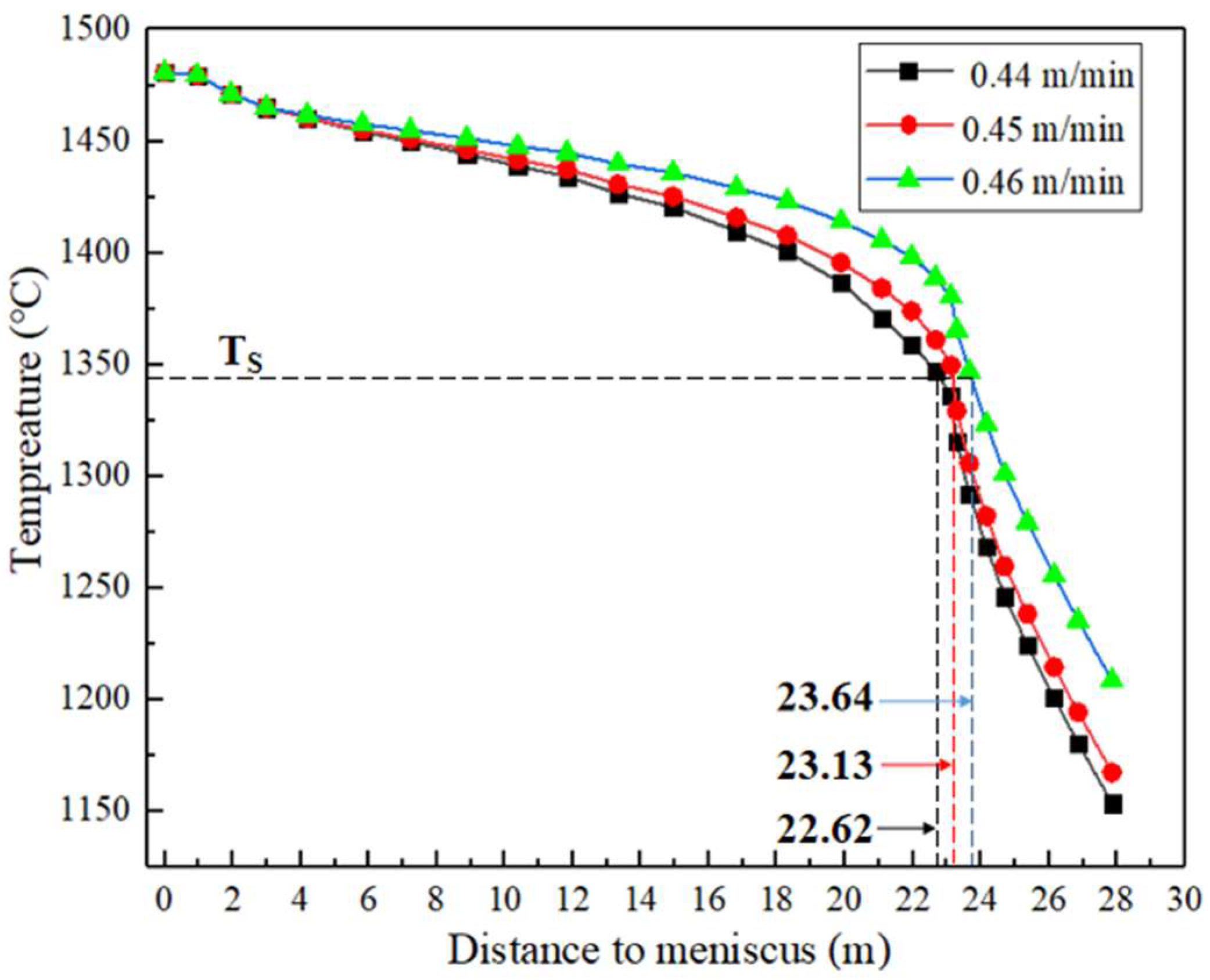
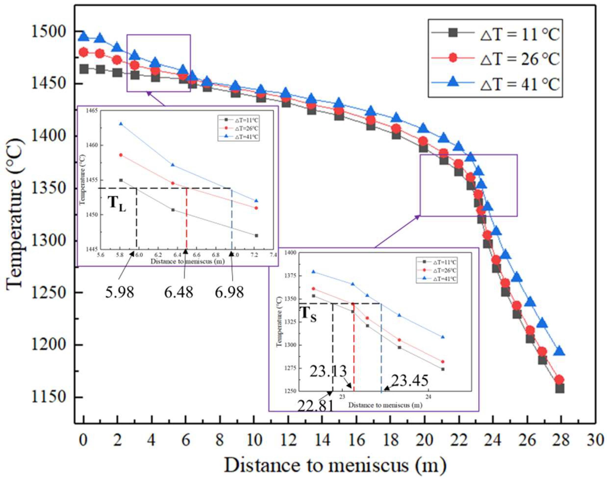
The solidification end point of 380 mm × 450 mm bearing steel bloom is 23.13 m from the meniscus. When the casting speed changes 0.01 m/min, the solidification end point changes 0.51 m. For every 15 °C change in superheat, the liquidus end-point of the bloom changes by 0.5 m, and the solidification end point changes by 0.32 m.
(2)
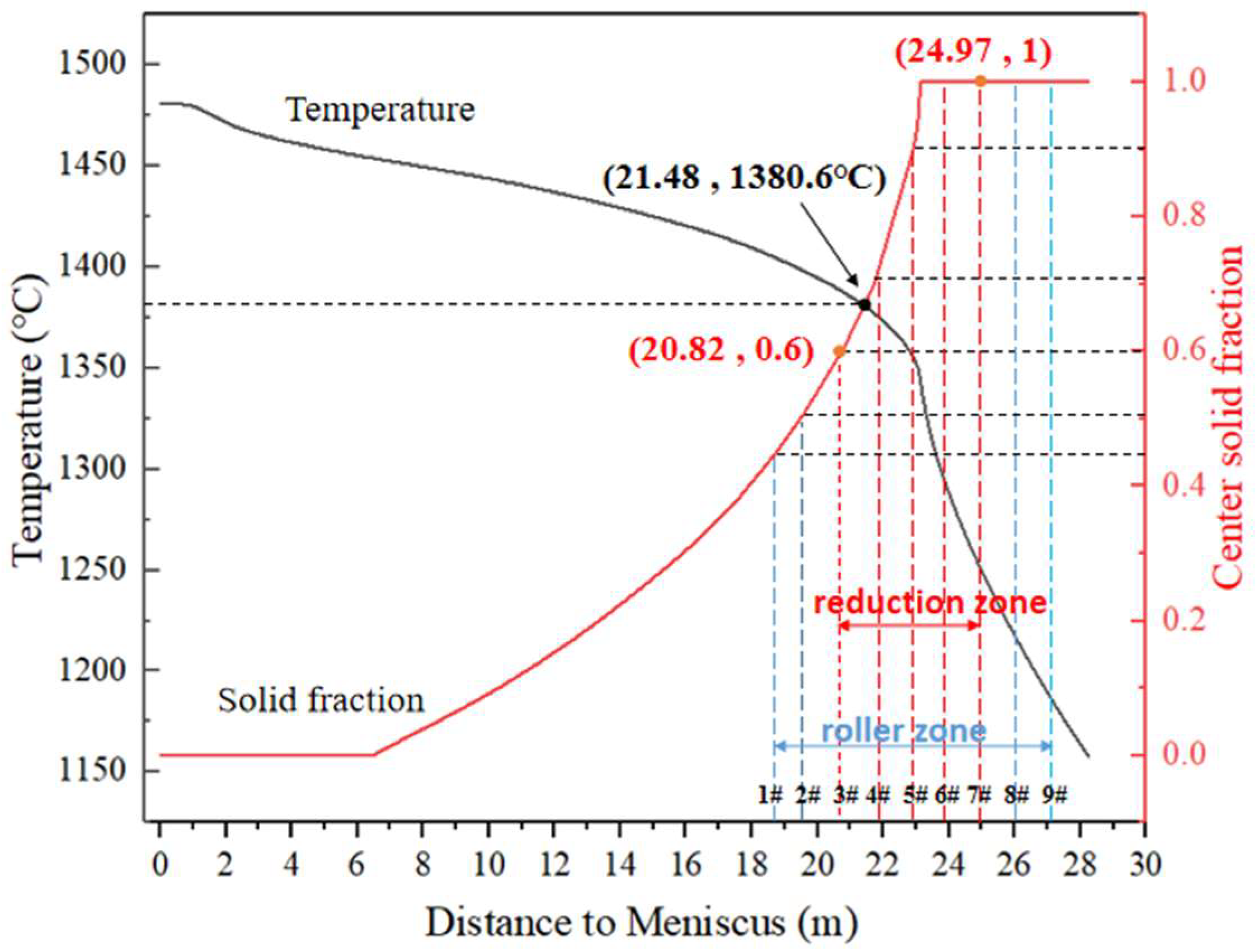
The central solid fraction of the solidification end of the 380 mm × 450 mm bearing steel bloom at the position of the 1 #~9 # pressure roller is 0.45, 0.51, 0.6, 0.71, 0.9, 1, 1,1, and 1, respectively. After optimizing HR, the central solid fraction range of the bloom reduction position is 0.6~1, the required reduction roller range is 3 #~7 #, and the distance to the meniscus is 20.82 m~24.97 m.
(3)
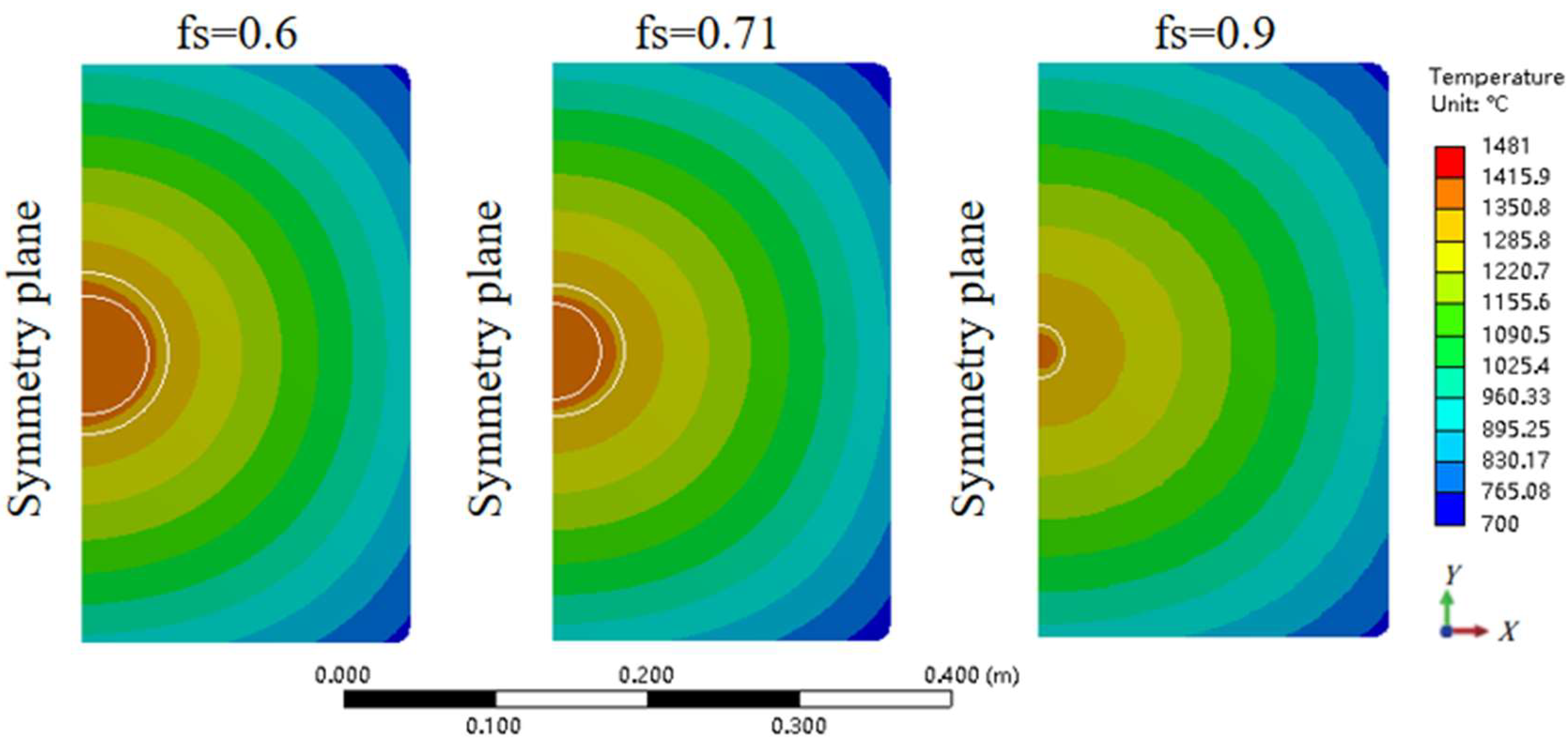
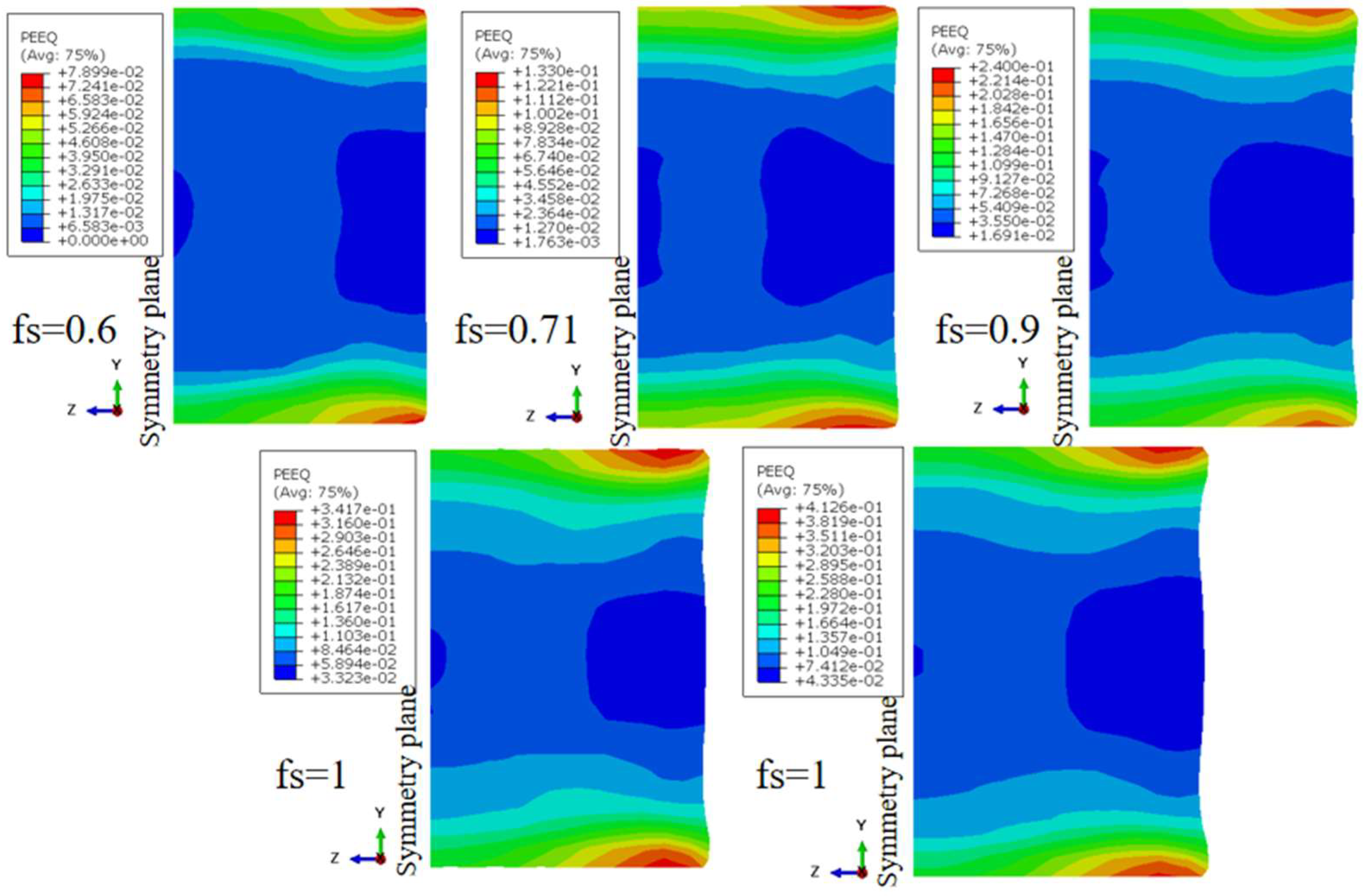
When the central solid fraction of 380 mm × 450 mm bearing steel bloom is 0.6, 0.71, and 0.9, the radius range of the high-incidence area of solidification front crack is 41 mm ≤ r ≤ 55 mm, 31.6 mm ≤ r ≤ 44.6 mm, and 0 ≤ r ≤ 19 mm, respectively.
(4)
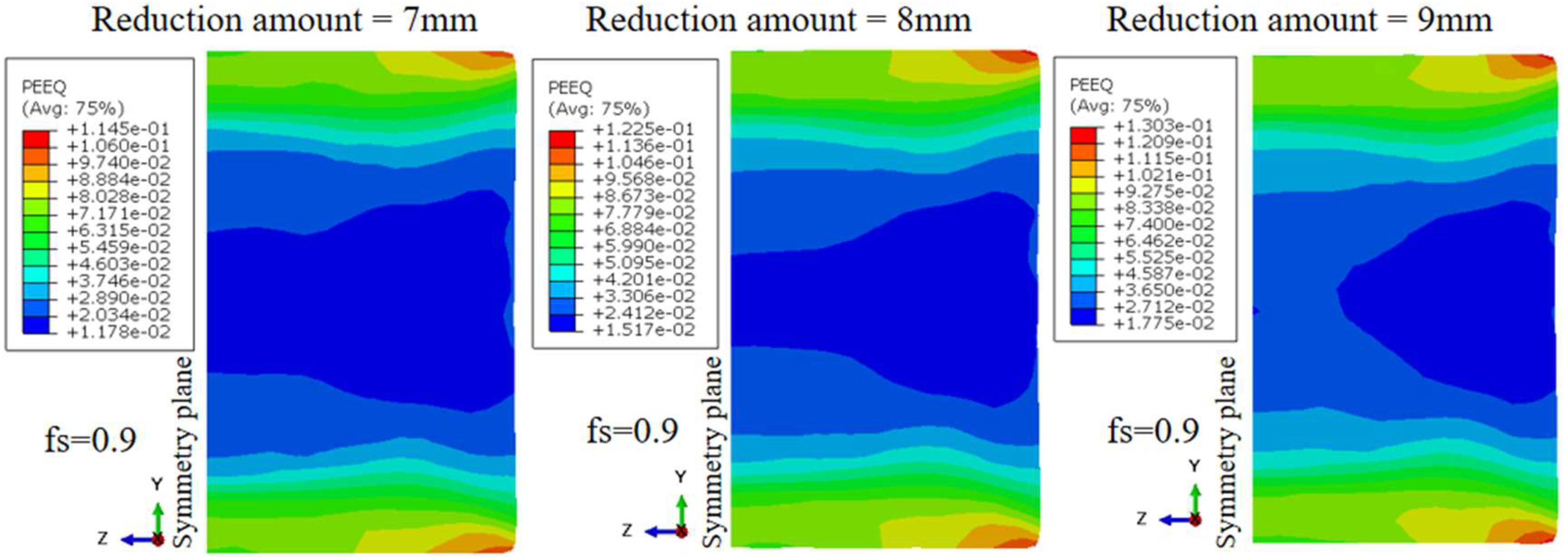
After optimization, the total reduction amounts of HR is 30 mm, and the reduction of 3 #~7 # rollers are 4 mm, 5 mm, 9 mm, 7 mm, and 5 mm respectively. The reduction will not make the bearing steel bloom solidification front crack.
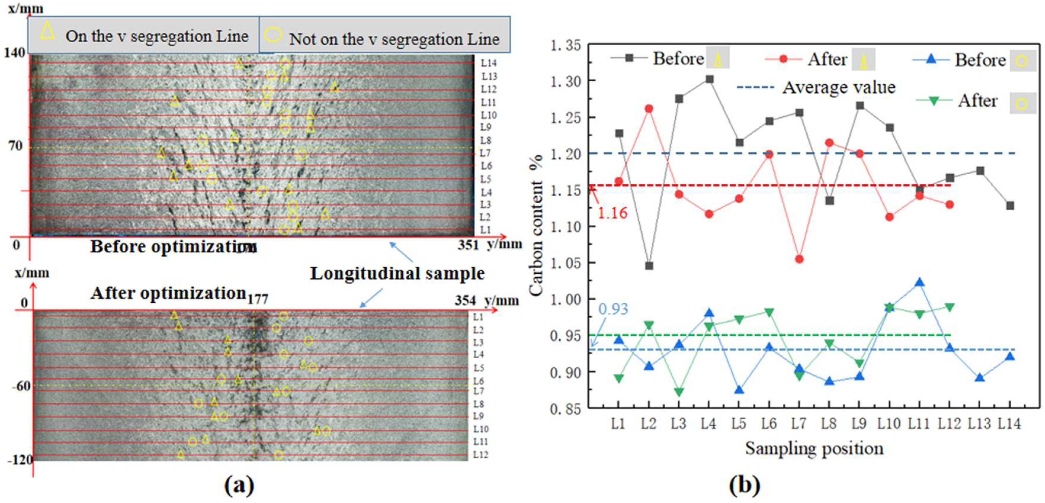
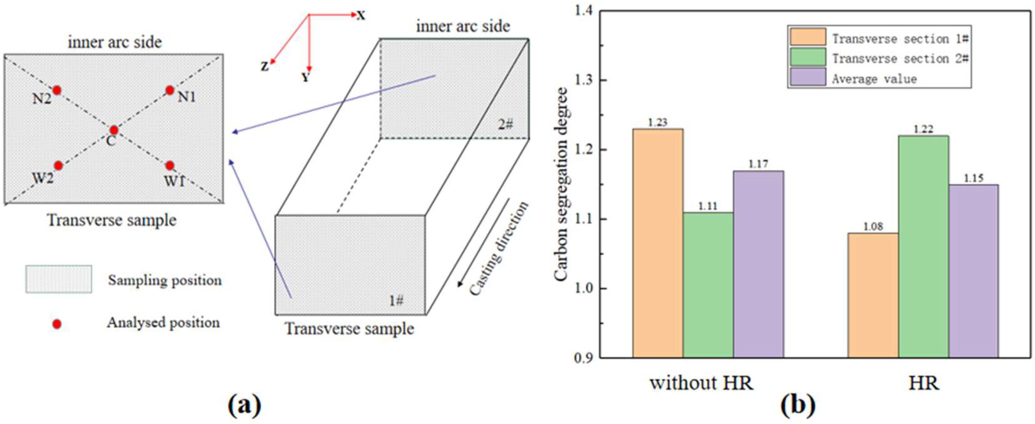
(5)
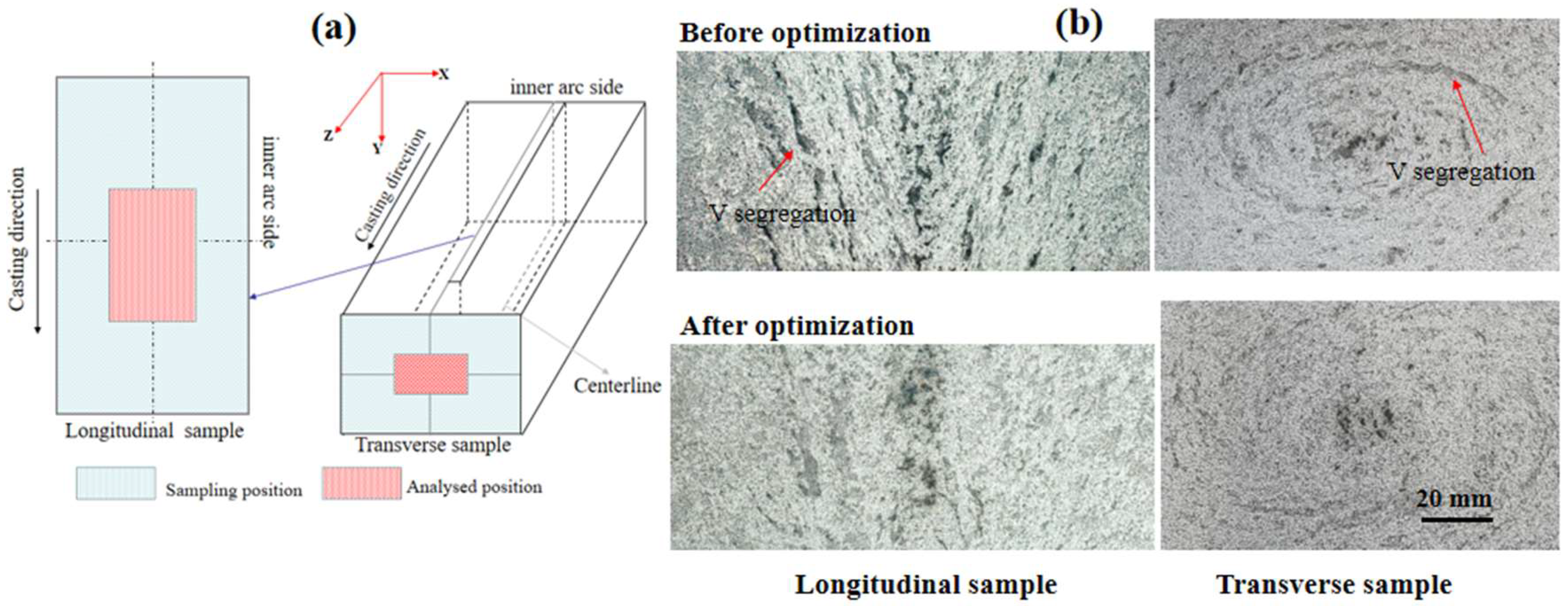
The results of plant experiments show that the optimized HR can effectively improve the macrosegregation of bearing steel GCR15 bloom. The average carbon content in the V segregation channel is reduced from 1.2% to 1.16%, and the average carbon content in the non-channel is increased from 0.93% to 0.95%. Meanwhile, the central carbon segregation degree decreased from 1.17 to 1.15.

Author Contributions

Conceptualization, M.W. and H.Z.; methodology, H.Z.; software, X.W.; validation, B.Y., M.W. and H.Z.; formal analysis, B.Y.; investigation, G.W.; resources, H.Z.; data curation, S.L.; writing—original draft preparation, B.Y.; writing—review and editing, M.W. and B.Y. All authors have read and agreed to the published version of the manuscript.

Funding

This research received no external funding.

Informed Consent Statement

Informed consent was obtained from all subjects involved in the study.

Conflicts of Interest

The authors declare no conflict of interest.

References

  1. Cen, Y.D.; Chen, L.; Dong, R. Effect of self-tempering on fatigue crack growth of heavy rail steel. Mater. Rep. 2021, 35, 12–36. [Google Scholar] [CrossRef]
  2. Li, H.G.; Ji, C.; Jiang, D.B.; Chen, T.M.; Guan, R.; Chen, L. Formation mechanism and control of semi-micro-segregation in rail steel bloom. Iron Steel 2021, 56, 59. [Google Scholar] [CrossRef]
  3. Wang, Y.D.; Zhang, L.F.; Zhang, H.J. Simulation of the macrosegregation in the gear steel billet continuous casting process. Chin. J. Eng. 2021, 43, 561. [Google Scholar] [CrossRef]
  4. Zhai, Y.Y.; Li, Y.; Yan, C.; Zhang, Y. Computational Prediction Model of Macrosegregation in Continuously Casting Steel Blooms. In Proceedings of the Second International Conference on Digital Manufacturing & Automation, Zhangjiajie, China, 5–7 August 2011; pp. 316–319. [Google Scholar]
  5. Sun, H.; Li, L. Application of swirling flow nozzle and investigation of superheat dissipation casting for bloom continuous casing. Ironmak. Steelmak. 2016, 43, 228. [Google Scholar] [CrossRef]
  6. Ren, B.; Chen, D.-F.; Wang, H.-D.; Long, M.-J.; Han, Z.-W. Numerical simulation of fluid flow and solidification in bloom continuous casting mould with electromagnetic stirring. Ironmak. Steelmak. 2015, 42, 401. [Google Scholar] [CrossRef]
  7. Wang, S.; De Toledo, G.A.; Välimaa, K.; Louhenkilpi, S. Magnetohydrodynamic phenomena, fluid control and computational modeling in the continuous casting of billet and bloom. ISIJ Int. 2014, 54, 2273. [Google Scholar] [CrossRef] [Green Version]
  8. Domitner, J.; Wu, M.; Kharicha, A.; Ludwig, A.; Kaufmann, B.; Reiter, J.; Schaden, T. Modeling the effects of strand surface bulging and mechanical softreduction on the macrosegregation formation in steel continuous casting. Metall. Mater. Trans. A 2014, 45, 1415. [Google Scholar] [CrossRef]
  9. Han, Y.; Yan, W.; Zhang, J.; Chen, W.; Chen, J.; Liu, Q. Optimization of Thermal Soft Reduction on Continuous-Casting Billet. ISIJ Int. 2022, 60, 106–113. [Google Scholar] [CrossRef] [Green Version]
  10. Lan, P.; Tie, Z.P.; Zhang, W. Research Progress on Spot Segregation Defects in Continuously Cast semi-products. Iron Steel 2020, 55, 11–20. [Google Scholar]
  11. Oh, K.S.; Chang, Y.W. Macrosegregation Behavior in Continuously Cast High Carbon Steel Blooms and Billets at the Final Stage of Solidification in Combination Stirring. ISIJ Int. 1995, 35, 866. [Google Scholar] [CrossRef] [Green Version]
  12. Han, Z.; Chen, D.; Feng, K.; Long, M. Development and Application of Dynamic Soft-reduction Control Model to Slab Continuous Casting Process. ISIJ Int. 2010, 50, 1637. [Google Scholar] [CrossRef]
  13. Moon, C.H.; Oh, K.S.; Lee, J.D.; Lee, S.J.; Lee, Y. Effect of the Roll Surface Profile on Centerline Segregation in Soft Reduction Process. ISIJ Int. 2012, 52, 1266. [Google Scholar] [CrossRef] [Green Version]
  14. Zhao, X.; Zhang, J.; Lei, S.; Wang, Y. The Position Study of Heavy Reduction Process for Improving Centerline Segregation or Porosity with Extra-Thickness Slabs. Steel Res. Int. 2014, 85, 645. [Google Scholar] [CrossRef]
  15. Rogberg, B.; Ek, L. Influence of Soft Reduction on the Fluid Flow, Porosity and Center Segregation in CC High Carbon- and Stainless Steel Blooms. ISIJ Int. 2018, 58, 478. [Google Scholar] [CrossRef] [Green Version]
  16. Sivesson, P.; Raihle, C.-M.; Konttinen, J. Thermal soft reduction in continuously cast slabs. Mater. Sci. Eng. A 1993, 173, 299. [Google Scholar] [CrossRef]
  17. Raihle, C.M.; Sivesson, P.; Tukiainen, M.; Fredriksson, H. Improving inner quality in continuously cast billets: Comparison between mould electromagnetic stirring and thermal soft reduction. Ironmak. Steelmak. 1994, 21, 487. [Google Scholar]
  18. Sivesson, P.; Örtlund, T.; Widell, B. Improvement of inner quality in continuously cast billets through thermal soft reduction and use of multivariate analysis of saved process variables. Ironmak. Steelmak. 1996, 23, 504. [Google Scholar]
  19. Sivesson, P.; Häilen, G.; Widell, B. Improvement of inner quality of continuously cast billets using electromagnetic stirring and thermal soft reduction. Ironmak. Steelmak. 1998, 25, 239. [Google Scholar]
  20. Ray, A.; Bhor, P.; Basu, D.; Sahay, S.; Paul, A.; Pradhan, N.; Tiwary, C.; Das, S.; Bandyopadhyay, A.; Bohidar, N. Improvement in internal quality of boiler plates at Bhilai Steel Plant. Ironmak. Steelmak. 2000, 27, 189. [Google Scholar] [CrossRef]
  21. Jung, Y.J.; Kim, J.J.; Kim, S.K.; Kang, C.G.; Korean, J. Investigated TSR on the centerline macro-segregation of stainless steel slab by numerical simulation and industrial test. Inst. Met. Mater. 2003, 41, 797. [Google Scholar]
  22. Yim, C.H.; Kil Park, J.; You, B.D.; Yang, S.M. The effect of soft reduction on center segregation in C.C. slab. ISIJ Int. 1996, 36, 231. [Google Scholar] [CrossRef]
  23. Chiang, L.K. Application of soft reduction technique for improving centerline segregation in continuously cast slab. In Steelmaking Conference Proceeding; Iron and Steel Society: Chicago, IL, USA, 1989; Volume 81. [Google Scholar]
  24. Engstrom, G.; Fredriksson, H.; Rogberg, B. On the mechanism of macrosegregation formation in continuously cast steels. Scand. J. Metall. 1983, 12, 3. [Google Scholar]
  25. Raihle, C.M.; Fredriksson, H. On the formation of pipes and centerline segregates in continuously cast billets. Metall. Mater. Trans. B 1994, 25, 123. [Google Scholar] [CrossRef]
  26. Han, Z.Q.; Lewis, R.W.; Liu, B.C. Modelling of the thermosolutal convection and macrosegregation in the solidification of an Fe-C binary alloy. Int. J. Numer. Methods Heat Fluid Flow 2007, 17, 313–321. [Google Scholar] [CrossRef]
  27. Jiang, D.; Wang, W.; Luo, S.; Ji, C. Mechanism of Macrosegregation Formation in Continuous Casting Slab: A Numerical Simulation Study. Metall. Mater. Trans. B 2017, 48, 3120–3131. [Google Scholar] [CrossRef]
  28. Tomono, H.; Hitomi, Y.; Ura, S.; Teraguchi, A.; Iwata, K.; Yasumoto, K. Mechanism of formation of the V-shaped segregation in the large section continuous cast bloom. ISIJ Int. 1984, 24, 917–922. [Google Scholar] [CrossRef]
  29. Abbott, T.B.; Hoyle, I.B.; Woodyatt, A.S. The 3-dimensional structure of macrosegregation in continuously cast high-carbon steel. Steel Res. 1994, 65, 28–131. [Google Scholar] [CrossRef]
  30. Ma, X.P.; Li, D.Z. Characterization, Mechanism and Control Measures of V Segregation in Continuous Casting Billet of C-Mn Steel. Metall. Mater. Trans. B 2019, 50, 1161–1170. [Google Scholar] [CrossRef]
  31. Zeng, Z.; Ji, C.X.; Zhang, H.Y.; Li, X.K.; Li, F.; Yang, X.S. Optimization experiment of soft reduction of continuous casting slab. Contin. Cast. 2018, 43, 23. [Google Scholar]
  32. Wang, W.; Hu, X.; Ning, L. Improvement of Center Segregation in High Carbon Steel Billets using Soft Reduction. J. Beijing Univ. Sci. Technol. Miner. Metall. Mater. 2006, 13, 490. [Google Scholar] [CrossRef]
  33. Wang, Z.M.; Wang, Y.H.; Cao, W.Q. Hot deformation behavior and processing maps of GCr15 bearing steel. Trans. Mater. Heat Treat. 2017, 38, 193. [Google Scholar]
  34. Kojima, S.; Mizota, H.; Kushida, K. Concept of continuous forging process and experimental analysis of forged blooms. Kawasaki Steel Tech. Rep. 1994, 26, 1. [Google Scholar]
  35. Nabeshima, S.; Nakato, H.; Fujii, T.; Fujimura, T.; Kushida, K.; Mizota, H. Control of centerline segregation of continuously cast billet by continuous forging process. Testu Hagane 1993, 79, 479. [Google Scholar] [CrossRef] [Green Version]
  36. Preßlinger, H.; Ilie, S.; Reisinger, P.; Schiefermüller, A.; Pissenberger, A.; Parteder, E.; Bernhard, C. Methods for assessment of slab center segregation as a tool to control slab continuous casting with soft reduction. ISIJ Int. 2006, 46, 1845. [Google Scholar] [CrossRef] [Green Version]
  37. Gan, Y.; Ni, M.S.; Yu, Z.X. Handbook of Modern Continuous Casting; Metallurgical Industry Press: Beijing, China, 2010. [Google Scholar]
  38. Clyne, T.W.; Wolf, M.; Kurz, W. The effect of melt composition on solidification cracking of steel, with particular reference to continuous casting. Metall. Mater. Trans. B 1982, 13, 259. [Google Scholar] [CrossRef]
  39. Li, C.S.; Thomas, B.G. Thermomechanical finite-element model of shell behavior in continuous casting of steel. Metall. Mater. Trans. B 2004, 35, 1151. [Google Scholar] [CrossRef]
  40. Kim, K.; Han, H.N.; Yeo, T. Analysis of surface and internal cracks in continuously cast beam blank. Ironmak. Steelmak. 1997, 24, 249. [Google Scholar]
  41. Won, Y.M.; Yeo, T.J.; Seol, D.J.; Oh, K.H. A new criterion for internal crack formation in continuously cast steels. Metall. Mater. Trans. B 2000, 31, 779. [Google Scholar] [CrossRef]
  42. Cai, Z.Z.; Ji, C.; Wang, W.L. Study on crack sensitivity of solidified billet shell in thick and wide slab continuous casting mould. In Proceedings of the 2012 Symposium on Crack Control Technology forContinuous Casting of Micro Alloyed Steel, Jiujiang, China, 1 May 2012; Volume 22. [Google Scholar]
  43. Cai, K.K. The Quality Control of the Continuous Casting Billet; Metallurgical Industry Press: Beijing, China, 2010. [Google Scholar]
  44. Wu, M.H.; Josef, D.; Andreas, L. Using a Two-Phase Columnar Solidification Model to Study the Principle of Mechanical Soft Reduction in Slab Casting. Metall. Mater. Trans. A 2012, 43, 945–964. [Google Scholar] [CrossRef]
  45. Zhong, X.D. Research on the Theory and Process of Soft Reduction in 350 mm × 470 mm Billet Continuous Casting; Northeast University: Shenyang, China, 2018. [Google Scholar]
  46. Kohichi, I. The realities of v segregation and the formation mechanism of segregation of continuously cast billets. Camp-ISIJ 2008, 21, 102–105. [Google Scholar]
  47. Barber, B.; Perkins, A. Strand deformation in continuous casting. Ironmak. Steelmak. 1989, 16, 406–411. [Google Scholar]
  48. Moore, J.J.; Shah, N.A. Mechanisms of formation of A- and V-segregation in cast steel. Int. Mater. Rev. 2013, 28, 336–356. [Google Scholar] [CrossRef]
  49. Santos, R.G.; Melo, M.L.N.M. Permeability of interdendritic channels. Mater. Sci. Eng. A 2005, 391, 151–158. [Google Scholar] [CrossRef]
Figure 1. Schematic diagram of the bloom continuous caster.
Metals 12 01873 g001
Figure 2. Solidification heat transfer model and cast-rolling model: (a) Geometric model of the slice, (b) Reduction finite-element of the bloom.
Metals 12 01873 g002
Figure 3. Physical parameters of the steel bearing GCR15.
Metals 12 01873 g003
Figure 4. Variation tendency diagram of center and surface temperature of bloom with distance to the meniscus.
Metals 12 01873 g004
Figure 5. Effect of casting speed on the final solidifying end.
Metals 12 01873 g005
Figure 6. Effect of superheat on the center temperature of bloom.
Metals 12 01873 g006
Figure 7. Variations of the temperature and solid fraction of bloom center of the case of casting speed of 0.45 m/min and average superheat of 26 °C.
Metals 12 01873 g007
Figure 8. Temperature distribution at the solidification front in the bloom.
Metals 12 01873 g008
Figure 9. Relationship between the carbon equivalent and critical strain.
Metals 12 01873 g009
Figure 10. Temperature distribution at different central solidification fractions.
Metals 12 01873 g010
Figure 11. Equivalent plastic strain under different reductions.
Metals 12 01873 g011
Figure 12. Equivalent plastic strain distribution on the transversal section of bloom under HR.
Metals 12 01873 g012
Figure 13. Schematic diagram of (a) sampling positions and (b) macrographs of etched samples.
Metals 12 01873 g013
Figure 14. Schematic diagram of (a) sampling positions and (b) carbon content of different positions.
Metals 12 01873 g014
Figure 15. Schematic diagram of (a) sampling positions and (b) comparison of carbon segregation at different positions.
Metals 12 01873 g015
Table 1. Chemical composition of the steel bearing GCR15.
CompositionCSiMnPSCrNiVCuAlFe
Mass fraction (%)0.980.280.350.0090.0021.460.020.0070.030.01996.76
Table 2. Main casting parameters of steel bearing GCR15.
ItemValue
Sectional dimension380 mm × 450 mm
Casting speed0.45 m/min
Pouring temperature1481 °C
Water flux of mold cooling222 m3/h
Temperature difference between
inlet and outlet of mold water
6 °C
Specific water of secondary cooling0.11 L/kg
E-MES parameters2.0 Hz/600 A
F-EMS parameters6.0 Hz/650 A
Table 3. The comparison of the simulated and measured surface temperatures.
Distance from the Meniscus (m)Simulated Temperature (°C)Measured Temperature (°C)Error Value
14.1102310351.16%
151011.810200.8%
16.29989950.3%
179899900.1%
Publisher’s Note: MDPI stays neutral with regard to jurisdictional claims in published maps and institutional affiliations.

