Article

Plasma Electrolytic Oxidation (PEO) Coating on γ-TiAl Alloy: Investigation of Bioactivity and Corrosion Behavior in Simulated Body Fluid

by
Fatemeh Salahshouri
1,
Ehsan Saebnoori
1,*,
Sina Borghei
2,
Majid Mossahebi-Mohammadi
3,
Hamid Reza Bakhsheshi-Rad
1 and
Filippo Berto
4,*
1
Advanced Materials Research Center, Department of Materials Engineering, Najafabad Branch, Islamic Azad University, Najafabad, Iran
2
School of Metallurgy and Materials Engineering, College of Engineering, University of Tehran, Tehran 16846, Iran
3
School of Pharmaceutical Sciences and International Collaborative Center on Growth Factor Research, Wenzhou Medical University, Wenzhou 325015, China
4
Department of Mechanical and Industrial Engineering, Norwegian University of Science and Technology, 7491 Trondheim, Norway
*
Authors to whom correspondence should be addressed.
Metals 2022, 12(11), 1866; https://doi.org/10.3390/met12111866
Submission received: 7 August 2022 / Revised: 12 September 2022 / Accepted: 26 October 2022 / Published: 1 November 2022
(This article belongs to the Special Issue Fatigue Behavior and Crack Mechanism of Metals and Alloys)

Abstract

:
The effect of applied voltage (400, 450, and 500 V) on the microstructure, bioactivity, and corrosion rate of plasma electrolytic oxidation (PEO) coatings on γ-TiAl alloy was investigated. The microstructure and chemical composition of the achieved coatings were studied, along with their corrosion and bioactivity behaviors in simulated body fluid (SBF). The results demonstrated that the higher the coating′s surface pore, the greater the number of suitable sites for the formation of hydroxyapatite with a spherical structure. The coatings applied utilizing 400, 450, and 500 V displayed 59.4, 96.6, and 145 Ω.cm2 as their inner layer electrical resistances, respectively. The findings of the biological examination revealed that Mesenchymal stem cells (MSCs) displayed more cytocompatibility and had a higher capacity for cell attachment in the PEO-coated sample than in γ-TiAl, as a result of better initial cell attachment made possible by the topography of the 500 V PEO coatings. The latter has significant potential to be employed in orthopedic applications.

1. Introduction

Titanium and its alloys are extensively used as biomaterials due to their preferable biocompatibility [1,2,3,4,5,6,7]. Although Ti6Al4V is the most prevalent titanium alloy in bone regeneration and replacement applications, its usage as a biomaterial is accompanied by some serious difficulties like the possibility of toxic element release, particularly vanadium, and low wear resistance [1,5,8,9,10]. Therefore, ever-increasing attention has been paid to vanadium-free titanium alloys as biocompatible materials over the past decades [11,12,13]. New generations of the γ-TiAl alloy, developed for aerospace and automotive applications, have emerged as viable candidates. This alloy has low density (3.8 g/cm3), high mechanical strength (up to 1000 MPa for ultimate tensile strength), elevated atmospheric corrosion, and high-temperature oxidation resistance [14,15,16]. The satisfactory biocompatibility of titanium alloys is mainly related to their reactive oxide layer, whose thickness is approximately 4–6 nm [1,6]. This amorphous or low-crystallinity oxide layer provides enhanced corrosion resistance against most aggressive media due to the chemical stability of this passive layer. However, there is still a high probability of the release of metallic ions when titanium alloys are exposed to corrosive physiologic media [17,18,19]. Researchers showed that long-term usage of titanium-based implants leads to severe diseases such as osteomalacia, neuropathy, and Alzheimer′s due to aluminum and vanadium ions released into the body [9,20,21]. Various methods of modifying and coating titanium surfaces have been proposed to overcome these drawbacks, such as plasma spray, sol-gel, and physical vapor deposition [22,23].
In recent years, plasma electrolytic oxidation (PEO), also known as micro-arc oxidation (MAO), has received growing attention because of its outstanding efficiency in ceramic coating and its utilization of environmentally-benign non-acidic electrolytes [24,25]. In addition, PEO-formed coatings are thicker, denser, and harder than other surface engineering techniques, leading to superior erosion, corrosion, thermal shock, electrical resistance, and strong bond strength of the substrate [26,27,28]. PEO coatings have untapped potential to improve the biocompatibility of titanium alloys. At the same time, the type, as well as, concentration, of the electrolyte profoundly affect the properties of the coating [29,30,31]. Inorganic phosphates have been widely used as the main electrolyte in biological applications to provide a sufficiently bioactive phosphorous [31,32,33]. Although there is some possibility for titanium alloys to release ions and make compounds like titanium nickelise causing aseptic inflammation for the surrounding tissues, it is believed that new 3D coatings have considerable potential to suppress this deterioration and release and accelerate the repair process by inducing osteogenic differentiation of the recipient bed stem cells [34,35,36]. These coatings must be biocompatible by maintaining periosteal stromal stem cell differentiation and facilitating cell colonization through structural porosity [37,38]. If these coatings increase the corrosion resistance against biological fluids, they will benefit titanium body implants [39,40,41].
To the best of the authors′ knowledge, no research has yet been done to examine the interactions between the PEO process operating parameters, acquired properties, corrosion, and bioactivity behaviors of PEO-coated γ-TiAl substrates. The impact of various PEO process parameters on the phase composition, microstructure, corrosion behavior, and biological characteristics of PEO coatings was therefore assessed in this research.

2. Experimental

2.1. Material and Coatings Preparation

Using electric discharge machining, cubic specimens were extracted from a γ-TiAl alloy and cut into 10 mm × 10 mm × 2 mm dimensions. The chemical composition of the alloy employed is shown in Table 1.
Before the PEO process, the specimens were manually ground using a series of abrasive SiC papers from 100 to 2000 grit, followed by chemical cleaning to remove surface oxides through immersion in hydrofluoric acid (48% purity), nitric acid (70% purity), and distilled water at a volume fraction ratio of 4:3.3:1 for 20 s (all reagents were of analytical grade). Then, the specimens were thoroughly washed by sonication in pure ethanol, rinsed with distilled water, and dried by blowing air. A unipolar pulsed DC power supply was utilized with various voltage modes set at 400, 450, and 500 V; and 2 A, 1000 Hz, and 10% as the maximum electric current, applied frequency, and duty cycle, respectively, were employed for the PEO process over a 10 min coating time. γ-TiAl specimens connected to the positive output of the power supply served as the working electrode (anode), and two stainless steel sheets (AISI 304) served as the counter electrode (cathode). The electrolyte temperature was maintained at about 25 °C throughout the coating process using a water-recirculating cooling system. One liter of distilled water was utilized to dissolve an alkaline calcium phosphate-based solution, containing 2.0 g of disodium phosphate (Na2HPO4) and 5.0 g of calcium acetate (Ca(C2H3O2)2), which served as the electrolyte.

2.2. Coating Characterization

The surface and cross-sectional morphology of the PEO coatings were examined using a scanning electron microscope (SEM; JEOL JSM -6380LA, Tokyo, Japan). Elemental detection of the coatings was evaluated with energy-dispersive X-ray spectroscopy (EDS). The quantitative examination of the pores on the PEO coating surface was obtained from the SEM image via ImageJ software. The crystal phases were identified using X-Ray Diffraction (XRD). The radiation source of the XRD (Philips PW3040, Eindhoven, The Netherlands) was CuKα generated at 40 and 100 mA and in a 2θ range of between 10° and 80°. Thickness measurements and percent of pore calculations were carried out on a cross-section micrograph of the coating utilizing Digimizer and ImageJ 1.44p image analysis software (Wayne Rasband, USA), respectively.

2.3. Corrosion Tests

Electrochemical impedance spectroscopy (EIS) measurements made by applying a sinusoidal perturbation potential of 10 mV (peak to peak) at the open circuit potential (OCP) in the frequency range of 100 kHz to 10 mHz were used on the specimens immersed in SBF (Table 2) to investigate the corrosion behaviors of the applied PEO coating. Before the electrochemical tests, samples were allowed to stabilize at their OCP in SBF for 30 min. These tests were performed in SBF (pH = 7.4) at 37 °C using Parstat 2273 potentiostat/galvanostat (EG&G, Oak Ridge, TN, USA) and a conventional three-electrode cell. In this cell, a saturated calomel electrode (SCE) was used as a reference electrode, a graphite rod was used as the auxiliary electrode, and the prepared specimens (with an exposed area of 1 cm2) were used as the working electrode. Zview (Serial No. 2402) software was served to analyze EIS results.

2.4. Bioactivity Assessment

To evaluate the bioactivity of the calcium phosphate-based coatings applied on γ-TiAl substrates, the specimens were immersed in SBF prepared based on [42] for 28 days at 36.5 °C using an incubator (BD 23 BINDER). The specimens were taken out, rinsed, and subsequently air-dried at the end of designated periods. SBFs have been developed to better mimic the physiological conditions, i.e., the chemical composition, in the body. In this study, the fluid was prepared by dissolving various reagent-grade compounds according to Bohner′s procedure [42]. SBF, whose ion concentrations and pH were nearly equal to those of the human blood plasma, can facilitate simultaneous nucleation and growth of bone-like calcium carbonate apatite at physiological pH and temperatures. Table 2 lists the reagent-grade ingredients used for the SBF preparation. The bioactivity of the PEO coating was assessed by examining the formation of apatite layers over the course of their immersion in SBF.

2.5. Biocompatibility Experiments

Mesenchymal stem cells (MSC) were isolated from bone marrow aspirates from three healthy individuals after obtaining informed consent, according to the medical ethics committee guidelines, of the Ministry of Health I.R, Iran. In brief, 10 ml of bone marrow aspirates were diluted with an equal volume of phosphate buffer saline (PBS; Invitrogen, USA), and three parts of diluted aspirates layered on one part of ficoll-paque in 50 ml conical tubes. (1.077) (GE Healthcare, USA). Following that, tubes were centrifuged at 400 G for 30 min at room temperature. Finally, the mononuclear cells layer was transferred to a T75 cell culture flask and incubated at 37 °C, 5% CO2 in low Glucose Dulbecco′s modified Eagle′s medium (DMEM; Invitrogen, USA). The medium was changed every 3 to 4 days until a confluent monolayer was achieved. Cells were differentiated into adipocytes and osteocytes to confirm the stem cell potential of the isolated MSCs. Flow cytometry was used to confirm isolated cells for cell surface markers: FITC-conjugated CD45, CD34, CD90, and PE-conjugated CD105, CD73, and HLA-DR. All antibodies were purchased from ebiosciences and assessed using FACSCalibur flow cytometry (Becton-Dickinson, San Diego, CA, USA).
Before cell seeding, PEO-coated γ-TiAl specimens (scaffolds) were immersed in 70% ethanol for sterilization. After 24 hours, the prepared scaffolds were air-dried and incubated in a DMEM culture medium to ensure that there was no contamination. Cells were harvested using Trypsin-EDTA (0.25%) (Sigma-Aldrich, St. Louis, MO, USA) and seeded on the scaffolds at the concentration of 5 × 10⁴ cells cm−2 and incubated at 37 °C and 5% CO2 for 72 h. After 72 hours of cell seeding, the scaffolds were assessed for cell attachment using SEM. The scaffolds were fixed with 2.5% glutaraldehyde for 2 h and washed twice with PBS. Samples were examined using a scanning electron microscope (S-4500; Hitachi, Tokyo, Japan) at an accelerating voltage of 20 kV.

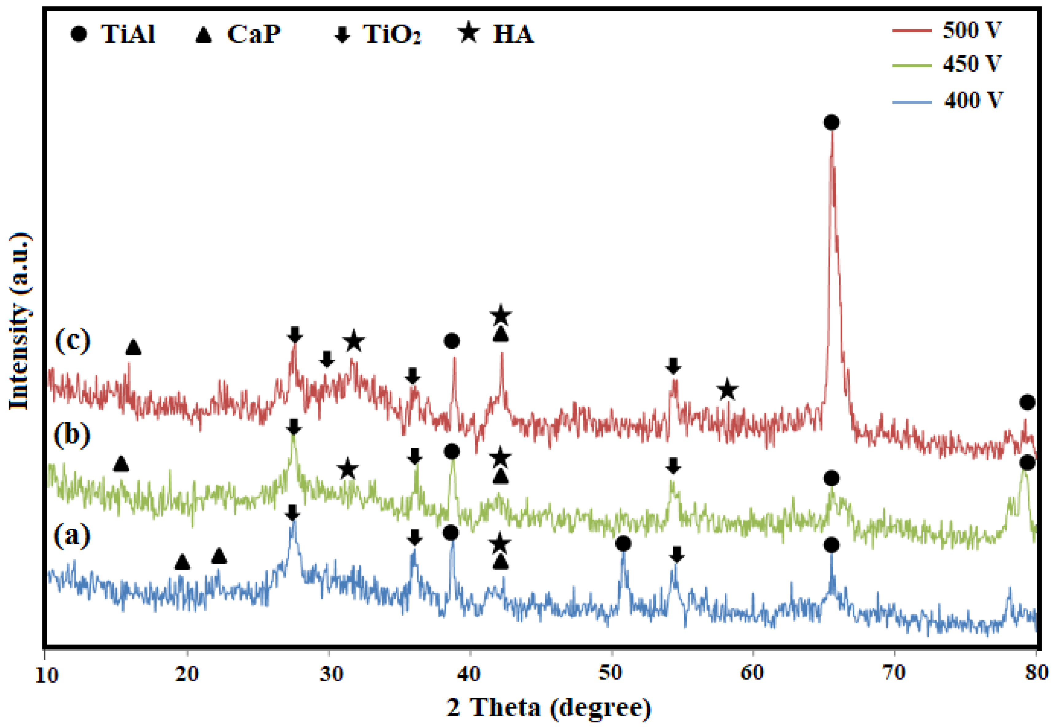
3. Results and Discussion

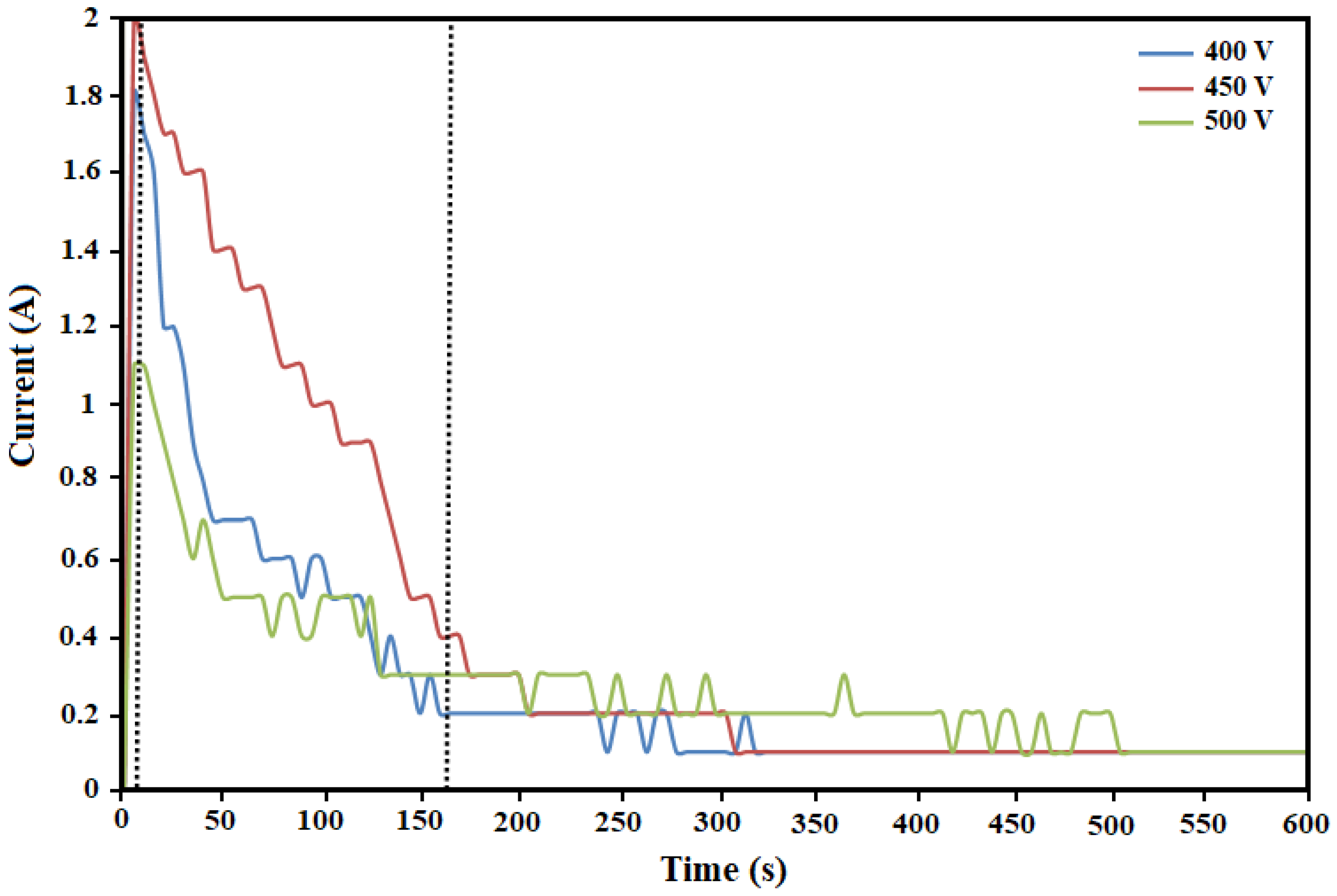
3.1. Characterization of Current Density during the PEO Process

Figure 1 shows the current-time curves of the specimens during the treatment process. The development of the anodic film with increasing current at constant voltage consists of three stages. During the first stage, a rapid rise in current density took place through a short period to values of 1.1, 1.8, and 2 A for the pre-set voltages of 400, 450, and 500 V, respectively, which was attributed to the formation of a thin surface layer corresponding to the conventional titanium alloy anodic oxidation process [27]. Oxygen evolution reactions partly occurred on the surface of the anode just before the dielectric breakdown of the protective layer (previously created by the conventional anodic oxidation of the substrate) and subsequent plasma discharge [43]. Meanwhile, the linear ohmic increase of current corresponded to the uniform formation of the oxide film. Although ion transport controlled the current rise, this became less dominant as the oxide layer thickened and increased electrical resistance [44]. Moreover, the substrates gradually darkened and lost their brightness over this stage, which was in agreement with prior studies [45]. At the beginning of the second stage, the surfaces of the specimens were illuminated with white glossy luminescence. At the same time, porous layers formed due to fluctuations and tiny sparks (when voltage surged to the breakdown value) over the working electrode surface [46]. The breakdown voltage of the oxide film is defined as a point when the potential reaches a threshold value that is sufficient to initiate ionization at the electrode-electrolyte interface [33]. As indicated in Figure 1, these values were about 1.1 A in 10 s, 1.8 A in 13 s, and 2 A in 25 s at voltages of 400, 450, and 500 V, respectively. A stronger electric field on the coating accompanied by a faint sound ascribed to intensive gas liberation on the surface of the anode characterized the second stage [47]. As the main characteristic of the PEO process, infinitesimal blue sparks first appeared at the edge of the specimens and then quickly spread across the surfaces in line with previous results [33,46,48]. During the second stage, the sparks enlarged and turned white, and their lifespan extended, indicating that the development of the coating had mostly already occurred [31]. In addition, the electric current did not alter until the specimens reached a stable constant potential, which is visible in the coating created by the applied voltage of 400 V. Hereafter, the PEO process was carried out at constant potential and falling current density for 3-4 min, which was mostly similar for all the specimens. The recorded differences in coating time and current among the samples likely pertain to the parallel effects of applied voltage on the rates of oxide film dissociation and the sparking process [43]. The third stage was characterized by sizeable and powerful yellow-colored sparks and a stable current density at its end [49]. The measured current diminished slowly to 0.2 A in the coating created at 400 V. However, at 450 V, the rate of current fall was dramatic until 0.4 A was reached and then decelerated to 0.2 A. At 500 V, there was a drastic decline to 0.7 A and only minor changes afterward. As seen in Figure 1, as the voltage rises, the current also rises quickly. This rapid increase in current is caused by the substrate dissolving and the creation of the porous anodized coating. When the voltage rises to the constant voltage, the current achieves its maximum value. The current then gradually diminishes and stabilizes with an extension of the PEO process time [27]. It has been reported [23] that as deposition time is increased, the current density drops as a result of the substrate′s increased surface resistance. This implies that the coating develops on the substrate surface progressively. The surface resistance won′t change once the coating has deposited on the substrate. The current density, therefore, maintains a specific value. The coating size does, however, steadily grow during the duration of the deposition process. This implies that the coating develops concurrently in the vertical and lateral directions.
XRD analysis (Figure 2) indicated that the PEO-coated γ-TiAl specimens prepared under applied voltages of 400 V, 450 V, and 500 V were mainly composed of titanium oxide (TiO2), titanium aluminide (TiAl), calcium titanate (CaTiO3), and hydroxyapatite (HA). In accordance with the applied voltages utilized throughout the PEO process, the peak intensities varied. The high intensity of titanium aluminide peaks correlated to whether the coating thickness was lower than the theoretical X-ray penetration depth or its porous structure facilitated interaction between the substrate and the X-rays [50]. Due to the great depth of X-ray penetration further into the pores and the fairly thin film, the TiAl substrate peaks were detected in all samples. According to earlier studies [23], raising the voltage of the PEO process to prepare nanocomposite coating could lead to an escalation in the extent and size of pores in the PEO coating, which could cause a reduction in the intensity of the peaks associated with the TiAl substrate [23,28]. Nevertheless, it was evident that raising the voltage from 400 V to 500 V increased the HAp peak intensity. As reported previously, CaTiO3 and Ca3(PO4)2 are the main constituents, and HA and TCP are found to be the minor structural phases in the PEO coating formed in calcium phosphate-based electrolytes [51,52,53]. The required activation energy for ionization of water, calcium, and phosphorous-containing compounds in the electrolyte and formation of complex structure ceramics like CaTiO3, and HA came from local temperature rises and the intense sparks due to requisite coating creation voltage increase along with higher applied current densities [50]. In this regard, it has been demonstrated [29] that calcium, titanium, and hydroxyl ions react to generate CaTiO3 phases, whereas calcium and phosphate, which are present at lower temperatures, react with each other to generate hydroxyapatite phases in the deposited film. Studies [29,34] have shown that CaTiO3 layers can assist in strengthening the bonding between titanium and hydroxyapatite as well as slow down the hydroxyapatite dissolving process in the acidic medium that is formed by osteoclastic resorption in the body. It is consequently assumed that by enhancing its osteogenic capabilities, the inclusion of these crystalline phases on the coated surface may favorably affect Ti′s bioactivity and cell response.
Figure 3 illustrates typical EDS spectra and SEM micrographs of surface morphology, and weight fractions for the five most-abundant elements in the coatings. The abundance of titanium, aluminum, calcium, phosphorous, and oxygen proved the incorporation of the electrolyte and substrate into the coating. The accelerated movement of chelating agent ions under a charge-transfer controlled mechanism toward the anodic oxidation coatings along with higher application voltage was inferred by the abundance of measured calcium content in the 500 V applied-voltage coating [54]. Moreover, the phosphorous content in the anodic oxidation coatings directly related to its source and presence along with oxygen corresponded to the formation of the phosphate group in the obtained PEO coatings [54,55]. As the microstructure of the PEO coating is closely connected to the applied current and voltage, it was expected to observe various characteristics in terms of surface morphology, and the number and size of pores considering the different recorded I-t curves (Figure 1) and applied voltages used in preparing the specimens. All coatings had a pancake-like structure, as a typical feature of the PEO process, with a non-uniform distribution of craters (discharge channels) over the surface [56,57]. These discharge channels are presented as dark circular spots in Figure 3. The reason for the pancake-like structure formation is the rapid ejection of the superficial melt (caused by process sparks) through discharge channels and its quick solidification (as a result of reaction with oxygen), leaving pores and boundaries [58]. It is probable for as-developed discharge channels to be fabricated on their former counterparts activating the sparks over the surface haphazardly and blocking adjacent channels. Even though a tiny percent of surface pores could develop to the substrate-coating interface, they were likely to be blocked by the molten material and subsequent solidification [59,60]. There is also an apparent difference between the coating and the electrolyte temperature as they reach thousands of degrees and 30–40 °C during plasma electrolytic oxidation, respectively. So along with such thermal shock, the abrupt solidification and its related shrinkage cause micro-cracks to form on the surface of the PEO coating [50].

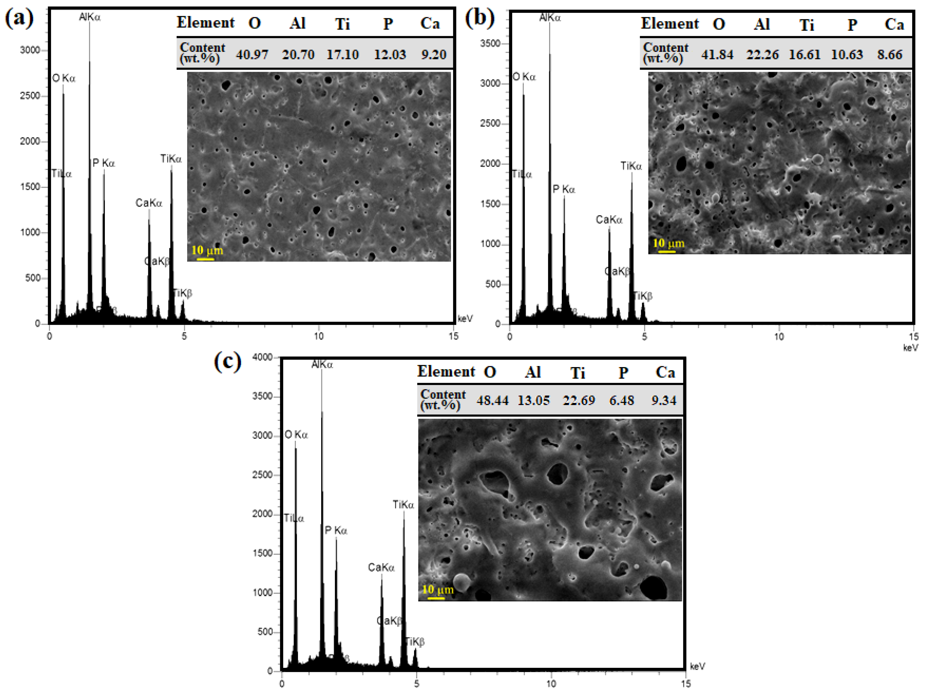
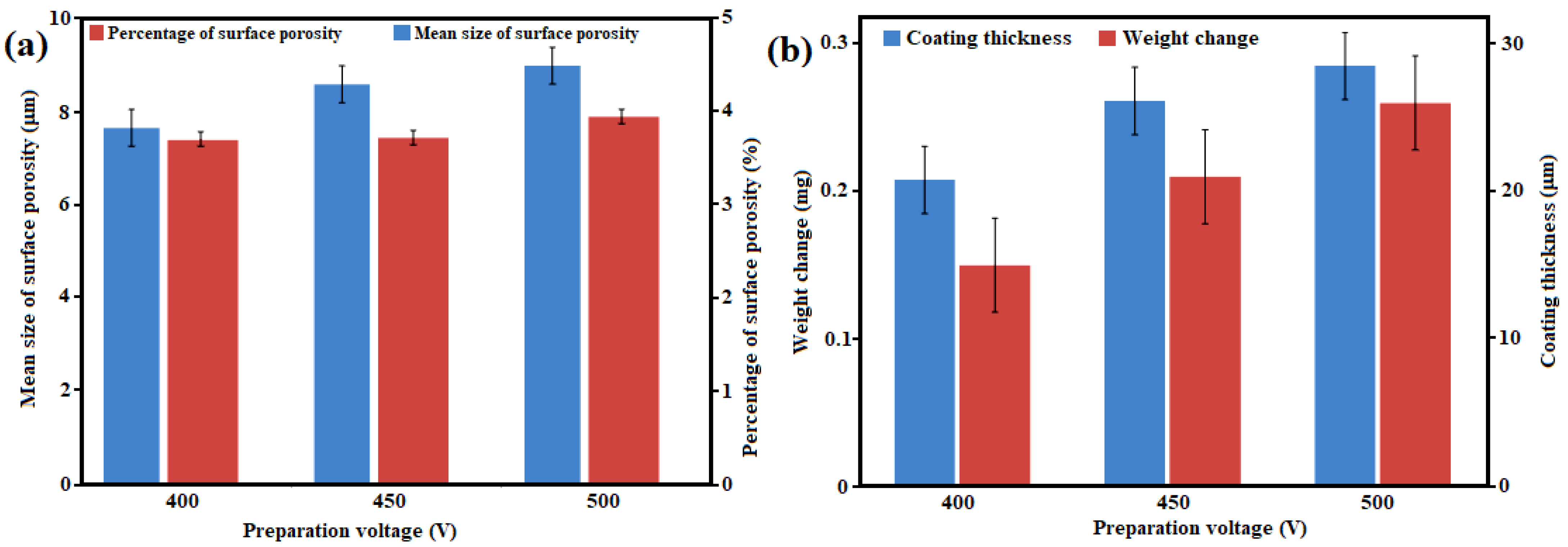
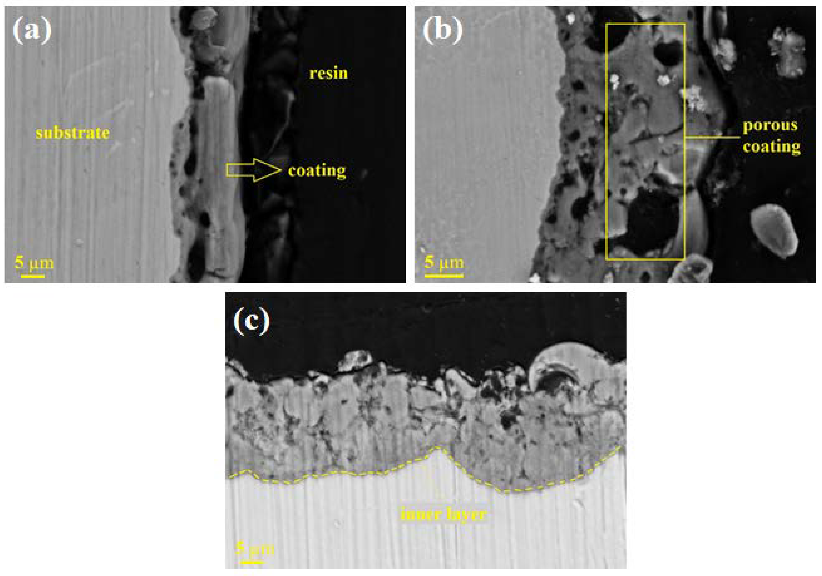
3.2. Pore, Weight Change, and Thickness Measurements

Figure 4a represents the percentage, and average surface pore of PEO coating prepared under different applied voltages. The results demonstrate that the decrease in the number of discharging sites through which greater anodic current can flow is responsible for the increase in the percentage and size of pores with rising voltage and time of the PEO process. Each spark-made pore is a preferred starting point for electric discharge due to its lower breakdown voltage in the coating microstructure. As previously reported, frequent electric discharge of sparks in a specific coating structure point results in greater pore formation [61]. In addition, the erratic pattern of electric discharge in terms of its location and time of occurrence triggers more intersections during PEO coating growth over the surface of the substrate [31]. Based on the results of Figure 4, the percentage of surface pores and their average size increased from 7.4 % and 3.83 µm to 7.9 % and 4.59 µm in parallel with the coating voltage increase from 400 V to 500 V, respectively. These results confirmed the variations in morphology observed in the micrographs presented in Figure 4 and can be explained by the intensification of applied current densities (Ohm′s law), leading to stronger imposed sparks. In addition, higher voltages boosted the provided energy for micro discharges, enlarging the magnitude of their channels, and increasing the coating surface roughness accordingly [62]. Similarly, the applied PEO voltage had a significant impact on the coating′s thickness and the specimen′s mass gain. In this respect, when the voltage rises, the specimen′s mass and coating thickness escalate steadily and roughly linearly (Figure 4b). Calculations based on Equation (1), as depicted in Figure 4b, proved that the induced current caused dissolution of the γ-TiAl substrate at the beginning of the process. When the accumulated electric charges on the surface of the substrate exceeded a critical value, dielectric breakdown occurred, and subsequently, plasma was discharged on the surface of the substrate [43]. Consequently, the plasma electrolytic oxidation coating started with the conversion of titanium to titanium oxides and calcium phosphate-based compounds. The main reason for the greater measured weight gain of specimens coated under higher voltages was faster conversion reactions leading to greater amounts of calcium phosphate-based compounds overcoming the accelerated substrate dissolution at the preliminary steps of PEO coating [24]. The weight change was calculated using Equation (1):
Δ W = M 2 M 1 M 2
where M1, M2, and ΔW represent the mass of the specimen before coating (mg), the mass of the specimen after coating (mg), and the weight change of the specimen (mg), respectively.
Cross-section micrographs of the PEO coatings prepared under different voltages are presented in Figure 5. The coating thickness was measured to be 20.78 µm, 26.13 µm, and 28.5 µm for the coatings formed at 400, 450, and 500 V, respectively. Internal pores may arise from oxygen evolution and solidification shrinkage during the PEO process. It is well-defined that the extreme process pressures and temperatures are responsible for the presence of dissolved oxygen in the molten materials [63]. This evolved oxygen is likely to be entrapped due to instant discharge sparks and rapid solidification [57]. A comparison between Figure 4a,b shows that the coating thickness and specimen′s weight increased at higher voltages. The low-voltage PEO process featured weak discharge sparks (a source of heat energy) and a ponderous coating growth rate. Therefore, the surrounding electrolyte possessed a dominant cooling capability against this small low-temperature melt [24]. The resultant quick solidification created a less porous network in the microstructure of the coating prepared under 400 V (Figure 5). The obtained coatings included a partly uniform outer layer and a dense inner layer. Fine pores in the inner layer were consolidated in the boundary region (with the outer layer) and formed larger pores. It is noteworthy that such pores grew as the applied voltage was enhanced. Large pores were the main cause of the thinning of the outer layer and they were filled with the used resin in the specimen preparation treatment by ultramicrotome. Since electric discharge sparks are generated by dielectric breakdown through weak sites in the coating, it is required for the PEO processing time to be short when high current densities and voltages are used for coating.

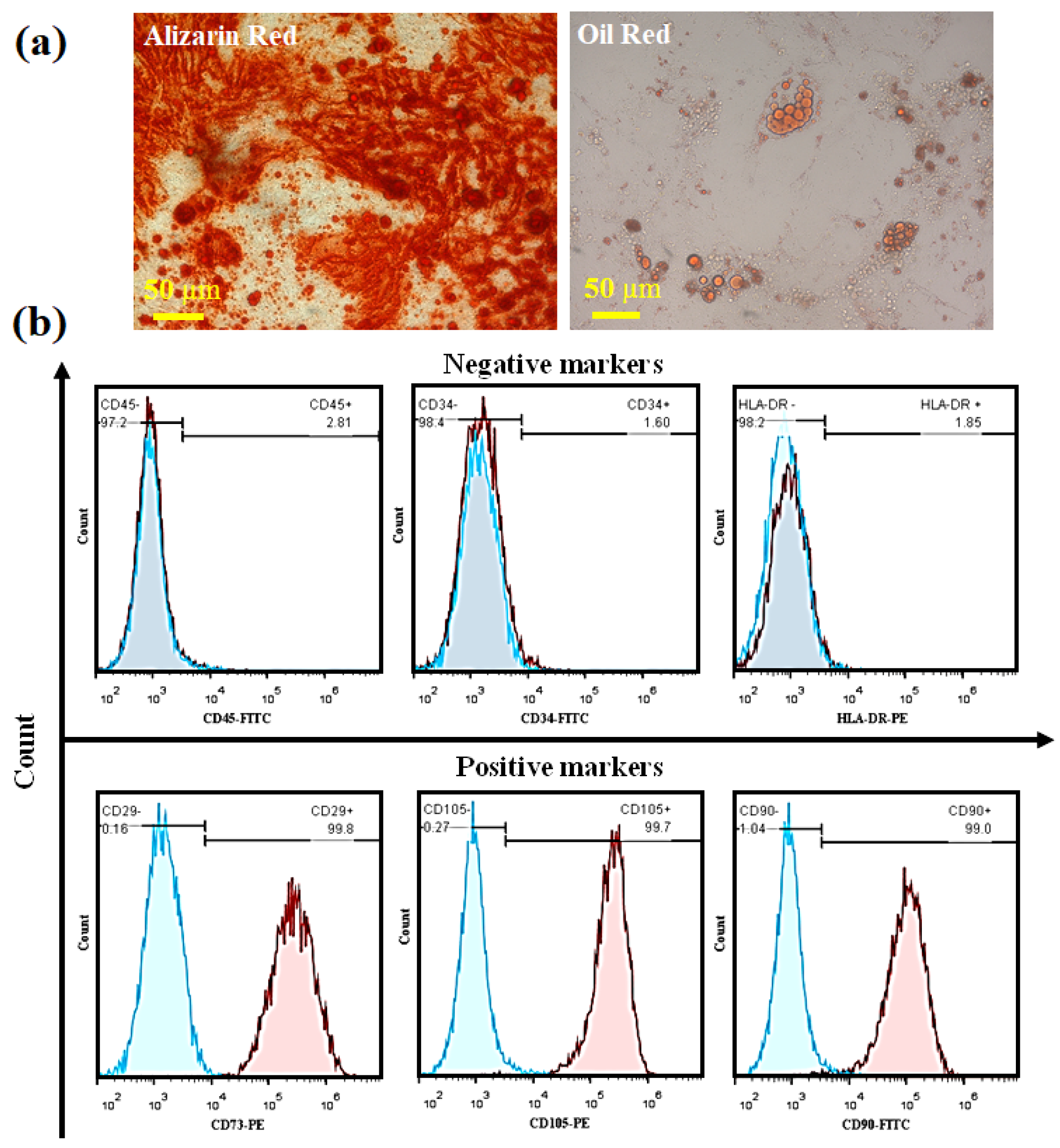
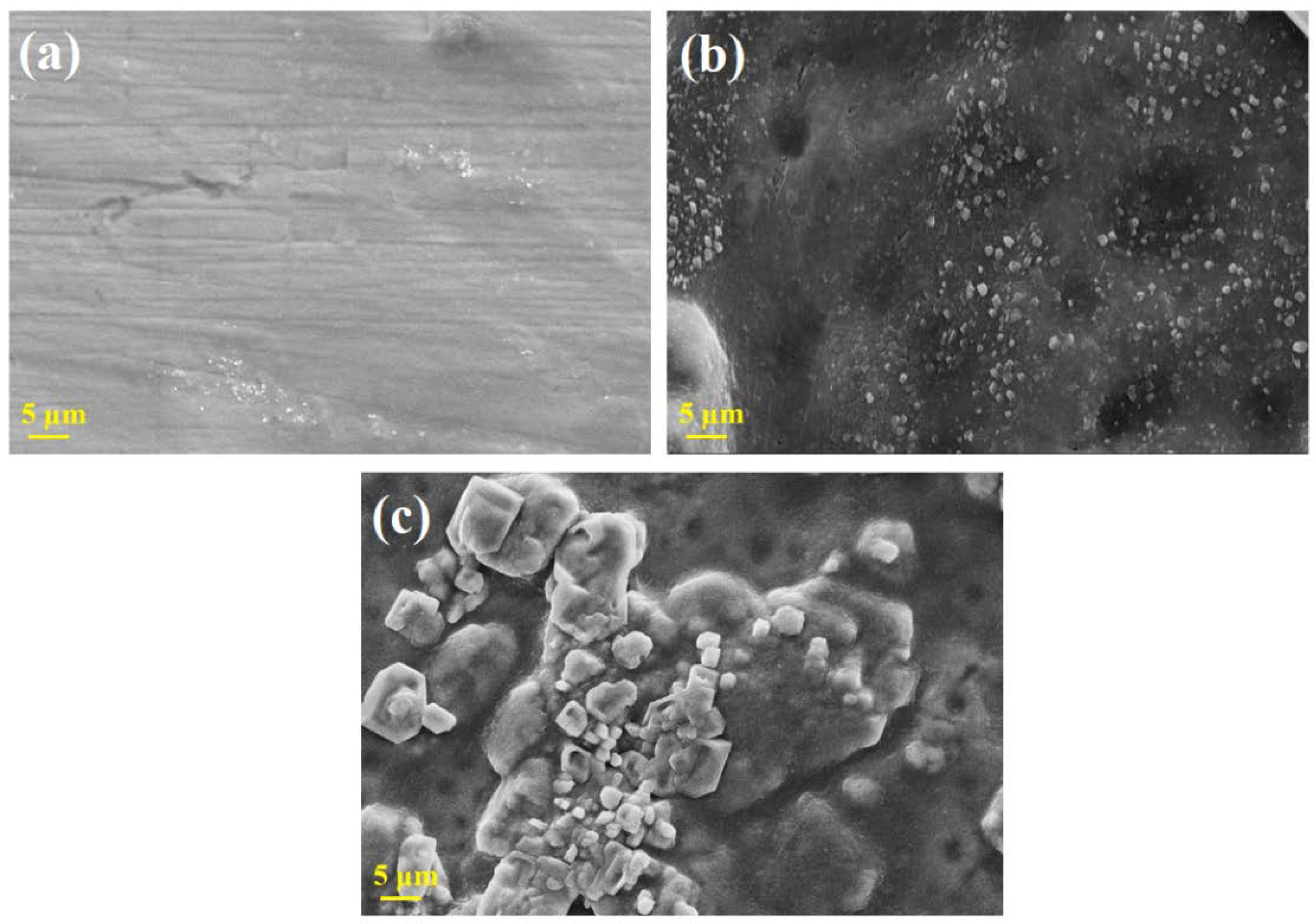
3.3. Bioactivity and Biocompatibility Assessments

To evaluate the bioactivity of the PEO-coated specimens by the formation of apatite on their surface, XRD analysis, and SEM/EDS investigations were performed on coated specimens previously immersed in SBF for 28 days. XRD patterns of PEO coatings immersed for 28 days in SBF at 36.5 °C shown in Figure 6. Generally, forming a layer of bone-like apatite is a vital requirement for the junction of implants (artificial components) to living bones, defined as an apatite-forming ability in the body [64]. Furthermore, the apatite formation on the surface of a coating in SBF represents its bioactivity in human body conditions [24]. It was apparent that the relative intensity of the hydroxyapatite (HAp) peaks was lower for the 400 V-applied coating compared to the other two coatings. This may be due to the formation of HAp in sub-micron-sized crystalline or amorphous phases. The appetite phase with hollow spheres and plate-like structures was made by mineralizing calcium phosphate-based compounds in SBF. Apatite configuration could be considered as a thermodynamic response to enhanced activities of calcium and phosphorous ions in SBF [65,66]. The porous structure of the PEO coatings facilitates the formation of the bone-like apatite in SBF by acting as nucleation support, reducing its standard enthalpy of formation [67]. Thus, the 500 V-applied PEO coating showed more intense HA peaks at 32.31o and 33.56o 2θ due to its 3D pore-rich structure. The apatite production of PEO-coated specimens has been reported to demonstrate the possibility of interfacial interaction between the implant surface and bone cells after implantation, which could perhaps improve osseointegration [13,14].
The results gathered from EDS studies, and morphological characteristics of the coatings are shown in Figure 7. The findings demonstrate that Ti, Al, O, P, and Ca were present in the surface elemental composition of all PEO-deposited films. There was a negligible increase and decrease in aluminum and titanium ions′ content, respectively, in the PEO coatings as the applied voltage was increased. O, P, and Ca were also present across the surface of the oxide films. Therefore, it is evident that the oxide films that were developed were rich in Ca, which may indicate the existence of calcium titanates. Moreover, the highest amounts of calcium and phosphorous ions were measured for the 500 V-applied PEO coating, which fully agreed with the relative intensity of this specimen′s hydroxyapatite peaks in the XRD analysis compared to its counterparts (Figure 6). The apatite could start to nucleate and grow on the porous surface of PEO coatings after immersion in SBF for just one day. For this reason, apatite thermodynamically precipitates on the pore walls and outer surfaces due to its excessive specific surface area. The apatite can still be deposited on non-porous substrates given its high activation energy. Soaking time allows the SBF to closely contact the coating and gradually crystallize apatitic nuclei by Ca2+ and PO43- reactants. There is a direct correlation between apatitic deposits and soaking time, attributed to the growing number and size of pores and thermal cracks and the potential nucleation sites during more extended immersion. At the end of this stage, volcano-like surface features (irregularities) are filled by apatite, as shown in the SEM micrographs of Figure 7. An additional driving force was required since the solution was not sufficiently saturated to cause homogenous apatite nucleation. This was provided by the increased soaking time, which elevated the saturation index of SBF around the surface of PEO coatings [68]. Calcium phosphate-based compounds are spontaneously formed on apatite nuclei as thermodynamically favorable sites. It was expected that the more porous surface of the 500 V-applied PEO coating significantly facilitated hollow spheres-structured apatite crystallization compared to the coatings applied under 400 and 450 V (Figure 7). The corrosion behavior of the γ-TiAl specimen was dramatically impacted via the creation of more HAp phases in the specimen prepared under an applied voltage of 500 V, as shown by the XRD analysis.
Isolated cells were attached to the T75 flask. The inclination confirmed the differentiation potential of stem cells toward osteogenic and adipogenic lineages. After 21 days of differentiation, cells were stained with alizarin red and oil red. As shown in Figure 8a, a mineralized matrix of differentiated MSCs to osteogenic was observed after staining with alizarin red. Moreover, the isolated cells demonstrated stem cells′ potential to differentiate to adipocytes after three weeks. In this study, cell surface markers were evaluated to show the stem cell potential of isolated cells. Isolated MSCs were positive for CD73, CD90, CD105, and negative for CD45, CD34, and HLA-DR (Figure 8b). According to previous studies [23], higher hydrophilicity escalates cell attachment, and distinct cell responses are elicited by nano- and micro-sized surfaces. The higher wettability at the PEO-coated sample is related to surface morphology containing nano-meshes or micro-pores formed on the surface. Ti surface topography and surface oxides can impact cell signal transduction, which alters how cells attach to one another and spread. Some oxides were found on the surfaces of titanium and its alloys after physical and chemical alteration, which raised the surface activities and escalated the hydrophilicity of Ti alloy surfaces. Thus, it becomes possible to enhance cell growth and create cell adhesion on the Ti alloy surface, making it easier for bone tissue to attach to a surface [12,13]. Bordbar-Khiabani et al. [36] produced calcium phosphate employing the PEO technique on a neat zinc substrate. Their findings demonstrated that the existence of calcium-phosphate in the hydrophilic PEO coatings improved the coatings′ hydrophilicity characteristics. According to the findings, coated samples covered with titanium oxide and HAp that were generated via the PEO technique at a high applied voltage were cytocompatible and were an excellent underlayer for cell growth. Therefore, preparing titanium implants coated with PEO film might be considered an appropriate candidate for biomedical uses such as bone tissue engineering.
Cells were seeded on specimens, incubated for 48 hours, and assessed using SEM to evaluate cellular bio-compatibility. As shown in Figure 9, cells were attached to the prepared specimens. It has been shown that the highest amounts of cells were attached on the PEO-coated specimen, which demonstrated that this specimen prepared the best bio-compatible surface for the attachment of MSCs. Although PEO-coated specimens performed better than the bare specimen in cellular attachment potential, superior bio-compatibility was detected for SBF-immersed specimens. TiO2 on the surface creates suitable conditions for forming calcium phosphate apatite crystals and speeds up their deposition. PEO coatings have a rough surface with a high degree of surface area for cell adhesion and growth. The cells on the uncoated sample′s smooth surface made very close contact with the substrate thanks to its profusion of filopodia and spread erratically in all directions with disorganized orientations. The rough surface of the PEO coating placed stronger limitations on the cell morphology, leading to the spherical shape of the cells. The oxides on the surface of a material may be a significant component in escalating cell osteogenic activity in addition to the impact on the surface morphology of the attached cell [12,13,14].

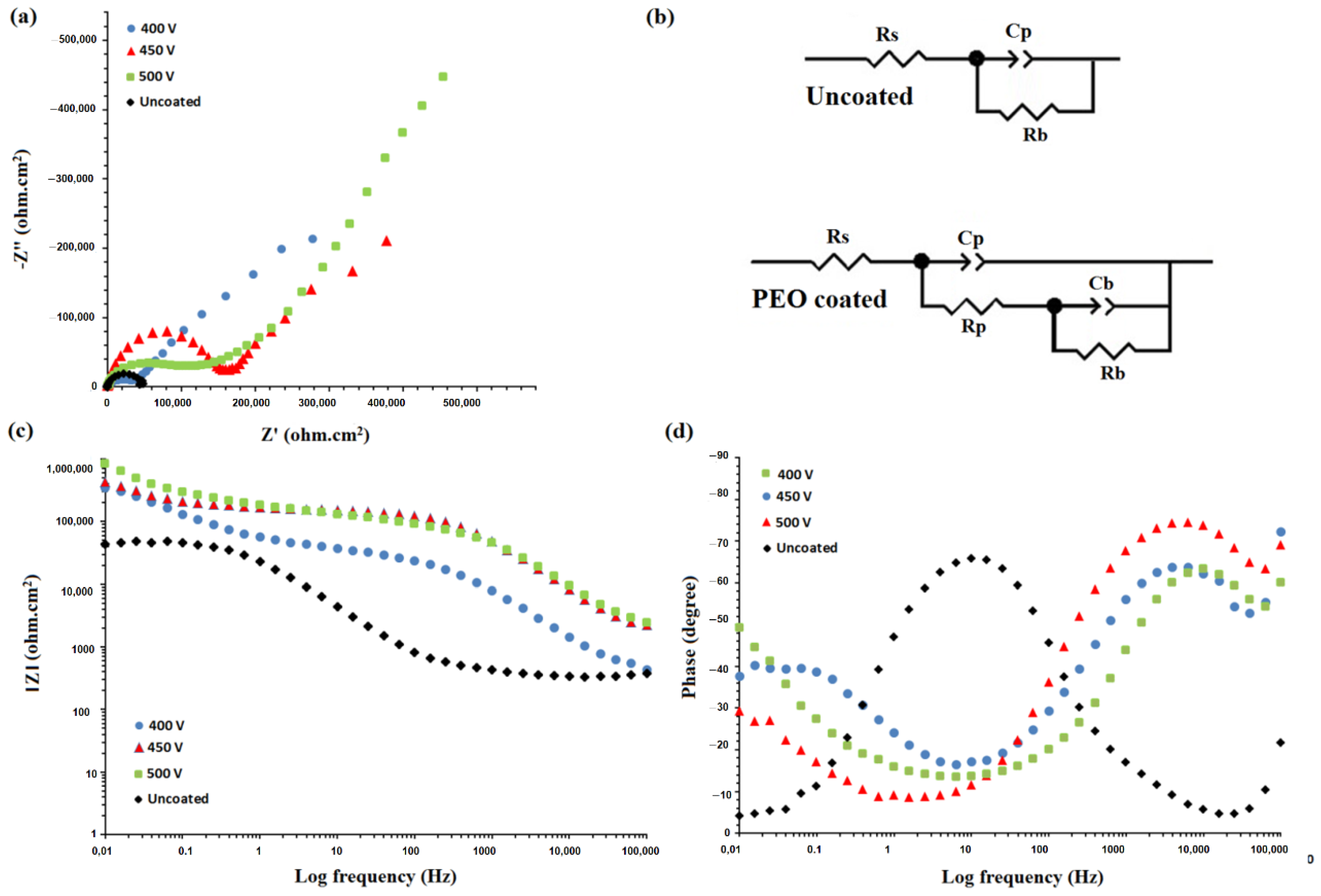
3.4. Electrochemical Impedance Spectroscopy (EIS)

Figure 10 plots the EIS results of the bare and PEO-coated specimens immersed for 30 min in SBF. Such coatings modify the corrosion resistance through restrictions on charge transfer and aggressive ions absorption [69]. The coatings formed in conventional anodic oxidation include a dense inner layer and a porous outer layer. The former thickens about a few microns and could be correlated to an electrical resistance element with infinite value in the electrochemical impedance test analysis if it was defectless [1,30]. PEO coatings are prone to corrosion due to their structurally open pores acting as diffusion pathways for corrosive ions reaching the substrate [70,71]. The equivalent circuits presented in Figure 10b were used to extract electrochemical parameters considering open pores extended to the surface of the substrate. Previous studies used the same equivalent circuits to obtain EIS parameters of PEO coatings. The two capacitive semicircles in the low and high-frequency ranges of Figure 10 correspond to the two layers featuring lower resistance of the inner porous layer subjected to discharge sparks during coating [72]. In this equivalent circuit Rs, Rp, and Rb represent the resistance of the test solution, the coating defects, and the substrate-coating interface, respectively. A corroding surface′s ideally polarizable activity is influenced by its physical properties, such as surface roughness. Due to the possible deviations from pure resistance (n = 0) or pure capacitance (n = 1) behaviors, a constant phase element (CPE) is used to represent the equivalent electrical properties of the double layer, where n is a dimensionless exponent in the CPE impedance (Z) calculation formula given as Equation (2) [73].
Z = 1 / Y 0 j ω n
where Y0 is the admittance, ω is the angular frequency of the sine wave (rad/s), and j is the imaginary coefficient 1 . As the value of Z indicates the contact area of the coating with the surrounding corrosive solution, its reduction pointed to less contact area and fewer surface pores and improved performance against corrosion. Hence, the corrosion resistance of the coated specimens was more significant than that of the substrate due to the incorporation of the dense inner and porous outer coating layers. The lower the capacitance, the less current density is required for the capacitor to be fully charged, so the formed PEO coatings prevent electric charge flow and reduce the corrosion rate within a short time [74,75,76]. The excessive values of charge transfer resistance (Rct) verified the significant protective effect of the coating′s inner layer or defect resistance to corrosion, conforming to several previous reports. Structural parameters such as phase composition, thickness, and morphology of the coating determine the number, size, and distribution of defects. As these defects acted as the main diffusion pathways for aggressive chloride ions toward the substrate and there was a direct relationship between the size/percent of surface pores and applied voltage, it was expected that the 500 V-applied coatings showed the highest corrosion resistance [77,78,79]. The PEO coating under an applied voltage of 500 V leads to a significant escalation in the Rct compared to the uncoated TiAl substrate. Thus, the trend in the Rct of the samples was: uncoated TiAl (49.6 kΩ m2) < 400 V (280.1 kΩ m2) < 450 V (380.2 kΩ m2) < 500 V (456.7 kΩ m2). In this regard, some researchers [80,81,82,83,84,85,86,87,88,89,90,91] have suggested that the substantial corrosion resistance in PEO coatings stems from the thickness of the oxide layer. Therefore, as the voltage rose, a thicker PEO film formed, which causes the penetration rate of the corrosive solution into the substrate to decrease; hence the chemical reactions culminating in the coating formation deaccelerated kinetically and thermodynamically. Accordingly, it was reasonable to correlate the superior corrosion resistance of the 500 V-applied coating to its thick oxide layer. Furthermore, it should be considered that when an applied voltage of 500 V was used in the PEO process, a compact inner layer and greater HAp were generated, causing the capacitance to be reduced and corrosion resistance to increase. The findings demonstrate that all PEO-deposited film samples had better corrosion performances than the uncoated TiAl.
In comparison to the 400 V and uncoated TiAl, the 500 V and 450 V samples exhibited a greater impedance value (|Z|) at low frequency (10–2 Hz), according to the Bode modulus plots (Figure 10c). This suggests that 500 V and 450 V samples have better corrosion resistance than the 400 V sample and uncoated TiAl alloy. The 500 V and 450 V samples, which were distinguished by having higher resistance, have comparable phase angle values, indicating the greater corrosion protection capabilities of the surface as the higher value of the curve moves to the right. Bode phase angles of 75° and 66° were recorded by the 500 V and 450 V samples, respectively; however, a lower phase angle of 62° was seen for the 400 V sample, implying weaker corrosion resistance (Figure 10d). Due to the low voltage and, the inhomogeneous coating process, variations in film thickness were noted. It is important to note that the small difference in thickness and irregularity between the 500 V and 450 V samples merely contributed to the decrease in surface porosity. Due to the high energy of the sparks, there were gaps in the film thickness in the 500 V and 450 V samples, which most likely extended to the substrate′s surface. The 500 V sample, meanwhile, was the most homogeneous and had a favorable thickness and density. Regardless of the occurrence of microcracks, the coating corrosion resistance escalated as the applied voltage rose. This is due to a diminishing in the number of large-size micropores, as well as a decrease in surface porosity and an elevation in film thickness. Furthermore, by applying a high operating voltage, a coating with the greatest thickness and dense inner structure can be created [28,37]. This is precisely why the 500 V PEO coating has superior corrosion resistance compared to the other samples.

4. Conclusions

PEO coatings were formed on γ-TiAl alloy using 400, 450, and 500 V voltages in a calcium phosphate-based solution. Based on the current-time curves, it was found that the current density increased at the beginning of the process and gradually decreased over its course. The highest current density was recorded under 500 V as the surface sparking was initiated sooner than under other applied voltages. An elevated coating voltage increases the content of calcium phosphate-based compounds and oxide phases in the coating and substrate, respectively. All coatings had a pancake-like structure featuring a non-uniform distribution of craters over the surface. Moreover, the size and extent of surface pores were directly correlated to the applied voltage, increasing from 7.4 % and 3.83 µm to 7.9 % and 4.50 µm for 400 and 500 V, respectively. Based on the SEM micrographs of the PEO coatings prepared under applied voltages of 400, 450, and 500 V, their thicknesses were measured to be 20.78, 26.13, and 28.50 µm respectively. The positive effect of applied voltage increase on the achieved coating thickness was further confirmed through the weight gain of specimens after coating. Bioactivity assessment of formed PEO coatings demonstrated that it was thermodynamically easier for hydroxyapatite to be nucleated on the more porous and 3D structure of the coatings applied under higher voltages. Corrosion measurements indicated that the 500 V PEO-coated sample had the highest corrosion resistance due to the formation of a dense inner layer and higher HAp formation. Considering both the corrosion behavior and biological characteristics of the 500 V PEO-coated sample, it should be considered an attractive candidate for application as a biomedical implant.

Author Contributions

Conceptualization, formal analysis, writing—original draft preparation, F.S. and S.B.; Conceptualization, supervision, writing—review and editing, E.S., M.M.-M. and H.R.B.-R.; writing—review and editing, funding acquisition, F.B. All authors have read and agreed to the published version of the manuscript.

Funding

This research received no external funding.

Institutional Review Board Statement

The study was conducted in accordance with the Declaration of Helsinki, and the protocol was approved by the national committee of Ethics for biomedical research (IR.MODARES.REC.1400.009).

Informed Consent Statement

All subjects gave their informed consent for inclusion before they participated in the study, with patient approval.

Data Availability Statement

All data provided in the present manuscript are available to whom it may concern.

Conflicts of Interest

The authors declare that they have no competing/financial conflict of interests.

References

  1. Jing, Z.; Cao, Q.; Jun, H. Corrosion, wear and biocompatibility of hydroxyapatite bio-functionally graded coating on titanium alloy surface prepared by laser cladding. Ceram. Int. 2021, 47, 24641–24651. [Google Scholar] [CrossRef]
  2. Chukwuike, V.I.; Shtansky, D.V.; Subramanian, B. Biocompatibility study of nanocomposite titanium boron nitride (TiBN) thin films for orthopedic implant applications. Surf. Coat. Technol. 2021, 410, 126968. [Google Scholar] [CrossRef]
  3. Quinn, J.; McFadden, R.; Chan, C.-W.; Carson, L. Titanium for Orthopedic Applications: An Overview of Surface Modification to Improve Biocompatibility and Prevent Bacterial Biofilm Formation. iScience 2020, 23, 101745. [Google Scholar] [CrossRef] [PubMed]
  4. Klyui, N.I.; Chornyi, V.S.; Zatovsky, I.V.; Tsabiy, L.I.; Buryanov, A.A.; Protsenko, V.V.; Temchenko, V.P.; Skryshevsky, V.A.; Glasmacher, B.; Gryshkov, O. Properties of gas detonation ceramic coatings and their effect on the osseointegration of titanium implants for bone defect replacement. Ceram. Int. 2021, 47, 25425–25439. [Google Scholar] [CrossRef]
  5. Samanta, A.; Rane, R.; Jhala, G.; Kundu, B.; Datta, S.; Ghosh, J.; Joseph, A.; Mukherjee, S.; Roy, S.; Mukhopadhyay, A.K. Biocompatibility and cyclic fatigue response of surface engineered Ti6Al4V femoral heads for hip-implant application. Ceram. Int. 2021, 47, 6905–6917. [Google Scholar] [CrossRef]
  6. Jiang, J.; Han, G.; Zheng, X.; Chen, G.; Zhu, P. Characterization and biocompatibility study of hydroxyapatite coating on the surface of titanium alloy. Surf. Coat. Technol. 2019, 375, 645–651. [Google Scholar] [CrossRef]
  7. Saebnoori, E.; Shahrabi, T.; Jafarian, H.; Ghaffari, M. Changes in the resistance to corrosion of thermally passivated titanium aluminide during exposure to sodium chloride solution. Res. Chem. Intermed. 2015, 41, 1079–1095. [Google Scholar] [CrossRef]
  8. Wang, G.; Wang, S.; Yang, X.; Yu, X.; Wen, D.; Chang, Z.; Zhang, M. Fretting wear and mechanical properties of surface-nanostructural titanium alloy bone plate. Surf. Coat. Technol. 2021, 405, 126512. [Google Scholar] [CrossRef]
  9. Kheder, W.; Al Kawas, S.; Khalaf, K.; Samsudin, A.R. Impact of tribocorrosion and titanium particles release on dental implant complications—A narrative review. Jpn. Dent. Sci. Rev. 2021, 57, 182–189. [Google Scholar] [CrossRef]
  10. Guo, X.; Bai, J.; Ge, G.; Wang, Z.; Wang, Q.; Zheng, K.; Tao, H.; Zhang, L.; Zhang, H.; Wang, D.; et al. Bioinspired peptide adhesion on Ti implants alleviates wear particle-induced inflammation and improves interfacial osteogenesis. J. Colloid Interface Sci. 2022, 605, 410–424. [Google Scholar] [CrossRef]
  11. Kaur, S.; Sharma, S.; Bala, N. A comparative study of corrosion resistance of biocompatible coating on titanium alloy and stainless steel. Mater. Chem. Phys. 2019, 238, 121923. [Google Scholar] [CrossRef]
  12. Zhan, X.; Li, S.; Cui, Y.; Tao, A.; Wang, C.; Li, H.; Zhang, L.; Yu, H.; Jiang, J.; Li, C. Comparison of the osteoblastic activity of low elastic modulus Ti-24Nb-4Zr-8Sn alloy and pure titanium modified by physical and chemical methods. Mater. Sci. Eng. C 2020, 113, 111018. [Google Scholar] [CrossRef] [PubMed]
  13. Fattah-alhosseini, A.; Molaei, M.; Nouri, M.; Babaei, K. Review of the role of graphene and its derivatives in enhancing the perfor-mance of plasma electrolytic oxidation coatings on titanium and its alloys. Appl. Surf. Sci. Adv. 2021, 6, 100140. [Google Scholar] [CrossRef]
  14. Xu, Y.; Shi, P.; Cui, S.; Li, Y.; Xu, A.; Wang, J.; Yao, Z.; Zhou, X.; Yuan, T.; Liu, W.; et al. Oxidation behavior of nano-structured (Al2O3 + Y2O3)/AlY coating on γ-TiAl upon exposure to 1200 °C. Ceram. Int. 2019, 45, 5163–5167. [Google Scholar] [CrossRef]
  15. Hua, K.; Wan, Q.; Tong, Y.; Yang, G.; Wu, H.; Zhou, Q.; Wang, H. Microstructural feature dependence of dry sliding wear behaviors in a γ-TiAl alloy. Wear 2021, 484–485, 204039. [Google Scholar] [CrossRef]
  16. Lin, H.; Liang, W.; Jia, Y.; Miao, Q.; Hu, R.; Ding, Z.; Yu, L. Effect of AlY gradient coating on hot corrosion resistance of γ-TiAl alloy at different temperatures. Appl. Surf. Sci. 2019, 487, 868–875. [Google Scholar] [CrossRef]
  17. Bodunrin, M.O.; Chown, L.H.; van der Merwe, J.W.; Alaneme, K.K.; Oganbule, C.; Klenam, D.E.P.; Mphasha, N.P. Corrosion behavior of titanium alloys in acidic and saline media: Role of alloy design, passivation integrity, and electrolyte modification. Corros. Rev. 2020, 38, 25–47. [Google Scholar] [CrossRef]
  18. Gabor, R.; Cvrček, L.; Doubková, M.; Nehasil, V.; Hlinka, J.; Unucka, P.; Buřil, M.; Podepřelová, A.; Seidlerová, J.; Bačáková, L. Hybrid coatings for orthopaedic implants formed by physical vapour deposition and microarc oxidation. Mater. Des. 2022, 219, 110811. [Google Scholar] [CrossRef]
  19. Saud, S.N.; Bakhsheshi-Rad, H.R.; Yaghoubidoust, F.; Iqbal, N.; Hamzah, E.; Ooi, C.R. Corrosion and bioactivity performance of graphene oxide coating on TiNb shape memory alloys in simulated body fluid. Mater. Sci. Eng. C 2016, 68, 687–694. [Google Scholar] [CrossRef]
  20. Manivasagam, G.; Dhinasekaran, D.; Rajamanickam, A. Biomedical Implants: Corrosion and its Prevention—A Review. Recent Pat. Corros. Sci. 2010, 2, 40–54. [Google Scholar] [CrossRef]
  21. Ali, S.; Abdul Rani, A.M.; Baig, Z.; Ahmed, S.W.; Hussain, G.; Subramaniam, K.; Hastuty, S.; Rao, T.V. Biocompatibility and corrosion resistance of metallic biomaterials. Corros. Rev. 2020, 38, 381–402. [Google Scholar] [CrossRef]
  22. Liu, X.; Chu, P.K.; Ding, C. Surface modification of titanium, titanium alloys, and related materials for biomedical applications. Mater. Sci. Eng. R Rep. 2004, 47, 49–121. [Google Scholar] [CrossRef] [Green Version]
  23. Azarian, N.; Khoei, S.M. Characteristics of a multi-component MgO-based bioceramic coating synthesized in-situ by plasma electrolytic oxidation. J. Magnes. Alloy 2021, 9, 1595–1608. [Google Scholar] [CrossRef]
  24. Rafieerad, A.R.; Ashra, M.R.; Mahmoodian, R.; Bushroa, A.R. Surface characterization and corrosion behavior of calcium phosphate-base composite layer on titanium and its alloys via plasma electrolytic oxidation: A review paper. Mater. Sci. Eng. C 2015, 57, 397–413. [Google Scholar] [CrossRef] [PubMed]
  25. Cao, F.; Lin, L.; Zhang, Z.; Zhang, J.; Cao, C. Environmental friendly plasma electrolytic oxidation of AM60 magnesium alloy and its corrosion resistance. Trans. Nonferrous Met. Soc. China 2008, 18, 240–247. [Google Scholar] [CrossRef]
  26. Hussein, R.O.; Nie, X.; Northwood, D.O. Influence of process parameters on electrolytic plasma discharging behaviour and aluminum oxide coating microstructure. Surf. Coat. Technol. 2010, 205, 1659–1667. [Google Scholar] [CrossRef]
  27. An, L.; Ma, Y.; Liu, Y.; Sun, L.; Wang, S.; Wang, Z. Effects of additives, voltage and their interactions on PEO coatings formed on magnesium alloys. Surf. Coat. Technol. 2018, 354, 226–235. [Google Scholar] [CrossRef]
  28. Molaeipour, P.; Allahkaram, S.R.; Akbarzadeh, S. Corrosion inhibition of Ti6Al4V alloy by a protective plasma electrolytic oxidation coating modified with boron carbide nanoparticles. Surf. Coat. Technol. 2022, 430, 127987. [Google Scholar] [CrossRef]
  29. Thukkaram, M.; Coryn, R.; Asadian, M.; Tabaei, P.S.E.; Rigole, P.; Rajendhran, N.; Nikiforov, A.; Sukumaran, J.; Coenye, T.; van der Voort, P.; et al. Fabrication of microporous coatings on titanium implants with improved mechanical, antibacterial, and cell-interactive properties. ACS Appl. Mater. Interfaces 2020, 12, 30155–30169. [Google Scholar] [CrossRef]
  30. Hamrahi, B.; Yarmand, B.; Massoudi, A. Improved in-vitro corrosion performance of titanium using a duplex system of plasma electrolytic oxidation and graphene oxide incorporated silane coatings. Surf. Coat. Technol. 2021, 422, 127558. [Google Scholar] [CrossRef]
  31. Aliofkhazraei, M.; Macdonald, D.D.; Matykina, E.; Parfenov, E.V.; Egorkin, V.S.; Curran, J.A.; Troughton, S.C.; Sinebryukhov, S.L.; Gnedenkov, S.V.; Lampke, T.; et al. Review of plasma electrolytic oxidation of titanium substrates: Mechanism, properties, applications and limitations. Appl. Surf. Sci. Adv. 2021, 5, 100121. [Google Scholar] [CrossRef]
  32. Durdu, S.; Usta, M. The tribological properties of bioceramic coatings produced on Ti6Al4V alloy by plasma electrolytic oxidation. Ceram. Int. 2014, 40, 3627–3635. [Google Scholar] [CrossRef]
  33. Aliasghari, S.; Skeldon, P.; Thompson, G.E. Plasma electrolytic oxidation of titanium in a phosphate/silicate electrolyte and tribological performance of the coatings. Appl. Surf. Sci. 2014, 316, 463–476. [Google Scholar] [CrossRef]
  34. Muhaffel, F.; Cempura, G.; Menekse, M.; Czyrska-Filemonowicz, A.; Karaguler, N.; Cimenoglu, H. Characteristics of multi-layer coatings synthesized on Ti6Al4V alloy by micro-arc oxidation in silver nitrate added electrolytes. Surf. Coat. Technol. 2016, 307, 308–315. [Google Scholar] [CrossRef]
  35. Kim, D.; Choi, B.; Song, J.; Kim, S.; Oh, S.; Jin, E.-H.; Kang, S.-S.; Jin, E.-J. TiO 2 nanotube stimulate chondrogenic differentiation of limb mesenchymal cells by modulating focal activity. Exp. Mol. Med. 2011, 43, 455–461. [Google Scholar] [CrossRef] [PubMed] [Green Version]
  36. Bordbar-Khiabani, A.; Ebrahimi, S.; Yarmand, B. In-vitro corrosion and bioactivity behavior of tailored calcium phosphate-containing zinc oxide coating prepared by plasma electrolytic oxidation. Corros. Sci. 2020, 173, 108781. [Google Scholar] [CrossRef]
  37. Kostelac, L.; Pezzato, L.; Settimi, A.G.; Franceschi, M.; Gennari, C.; Brunelli, K.; Rampazzo, C.; Dabalà, M. Investigation of hydroxyapatite (HAP) containing coating on grade 2 corrosion and bioactivity behavior electrolytic oxidation (PEO) at low voltage. Surf. Interfaces 2022, 30, 101888. [Google Scholar] [CrossRef]
  38. Tsimbouri, P.M.; Murawski, K.; Hamilton, G.; Herzyk, P.; Oreffo, R.O.C.; Gadegaard, N.; Dalby, M.J. A genomics approach in determining nanotopographical effects on MSC phenotype. Biomaterials 2013, 34, 2177–2184. [Google Scholar] [CrossRef] [Green Version]
  39. Kumar, A.; Biswas, K.; Basu, B. Hydroxyapatite-titanium bulk composites for bone tissue engineering applications: Ha-Ti Bulk Composites for Bone Tissue Engineering Applications. J. Biomed. Mater. Res. Part A 2014, 103, 791–806. [Google Scholar] [CrossRef]
  40. Daroonparvar, M.; Yajid, M.A.; Gupta, R.K.; Yusof, N.M.; Bakhsheshi-Rad, H.R.; Ghandvar, H. Investigation of corrosion protection performance of multiphase PEO (Mg2SiO4, MgO, MgAl2O4) coatings on Mg alloy formed in aluminate-silicate-based mixture electrolyte. Prot. Met. Phys. Chem. Surf. 2018, 54, 425–441. [Google Scholar] [CrossRef]
  41. Zhang, Z.Q.; Wang, L.; Zeng, M.Q.; Zeng, R.C.; Kannan, M.B.; Lin, C.G.; Zheng, Y.F. Biodegradation behavior of micro-arc oxidation coating on magnesium alloy-from a protein perspective. Bioact. Mater. 2020, 5, 398–409. [Google Scholar] [CrossRef] [PubMed]
  42. Bohner, M.; Lemaitre, J. Can bioactivity be tested in vitro with SBF solution? Biomaterials 2009, 30, 2175–2179. [Google Scholar] [CrossRef] [PubMed] [Green Version]
  43. Gao, Y.; Yerokhin, A.; Parfenov, E.; Matthews, A. Application of Voltage Pulse Transient Analysis during Plasma Electrolytic Oxidation for Assessment of Characteristics and Corrosion Behaviour of Ca- and P-containing Coatings on Magnesium. Electrochim. Acta 2014, 149, 218–230. [Google Scholar] [CrossRef]
  44. Matykina, E.; Arrabal, R.; Scurr, D.J.; Baron, A.; Skeldon, P.; Thompson, G.E. Investigation of the mechanism of plasma electrolytic oxidation of aluminium using 18O tracer. Corros. Sci. 2010, 52, 1070–1076. [Google Scholar] [CrossRef]
  45. Lin, X.; Tan, L.; Zhang, Q.; Yang, K.; Hu, Z.; Qiu, J.; Cai, Y. The in vitro degradation process and biocompatibility of a ZK60 magnesium alloy with a forsterite-containing micro-arc oxidation coating. Acta Biomater. 2013, 9, 8631–8642. [Google Scholar] [CrossRef]
  46. Quintero, D.; Galvis, O.; Calderón, J.A.; Castaño, J.G.; Echeverría, F. Effect of electrochemical parameters on the formation of anodic films on commercially pure titanium by plasma electrolytic oxidation. Surf. Coat. Technol. 2014, 258, 1223–1231. [Google Scholar] [CrossRef]
  47. Troughton, S.C.; Nominé, A.; Nominé, A.V.; Henrion, G.; Clyne, T.W. Synchronised electrical monitoring and high speed video of bubble growth associated with individual discharges during plasma electrolytic oxidation. Appl. Surf. Sci. 2015, 359, 405–411. [Google Scholar] [CrossRef] [Green Version]
  48. Galvis, O.A.; Quintero, D.; Castaño, J.G.; Liu, H.; Thompson, G.E.; Skeldon, P.; Echeverría, F. Formation of grooved and porous coatings on titanium by plasma electrolytic oxidation in H2SO4/H3PO4 electrolytes and effects of coating morphology on adhesive bonding. Surf. Coat. Technol. 2015, 269, 238–249. [Google Scholar] [CrossRef]
  49. Blawert, C.; Karpushenkov, S.A.; Serdechnova, M.; Karpushenkava, L.S.; Zheludkevich, M.L. Plasma electrolytic oxidation of zinc alloy in a phosphate-aluminate electrolyte. Appl. Surf. Sci. 2020, 505, 144552. [Google Scholar] [CrossRef]
  50. Sun, J.; Han, Y.; Huang, X. Hydroxyapatite coatings prepared by micro-arc oxidation in Ca- and P-containing electrolyte. Surf. Coat. Technol. 2007, 201, 5655–5658. [Google Scholar] [CrossRef]
  51. Sowa, M.; Piotrowska, M.; Widziołek, M.; Dercz, G.; Tylko, G.; Gorewoda, T.; Osyczka, A.M.; Simka, W. Bioactivity of coatings formed on Ti–13Nb–13Zr alloy using plasma electrolytic oxidation. Mater. Sci. Eng. C 2015, 49, 159–173. [Google Scholar] [CrossRef] [PubMed]
  52. Gu, X.N.; Li, N.; Zhou, W.R.; Zheng, Y.F.; Zhao, X.; Cai, Q.Z.; Ruan, L. Corrosion resistance and surface biocompatibility of a microarc oxidation coating on a Mg–Ca alloy. Acta Biomater. 2011, 7, 1880–1889. [Google Scholar] [CrossRef] [PubMed]
  53. Song, W.-H.; Jun, Y.; Han, Y.; Hong, S.-H. Biomimetic Apatite Coating on Micro-Arc Oxidized Titania. Biomaterials 2004, 25, 3341–3349. [Google Scholar] [CrossRef]
  54. Qiao, L.P.; Lou, J.; Zhang, S.F.; Qu, B.; Chang, W.H.; Zhang, R.F. The entrance mechanism of calcium and phosphorus elements into micro arc oxidation coatings developed on Ti6Al4V alloy. Surf. Coat. Technol. 2016, 285, 187–196. [Google Scholar] [CrossRef]
  55. Yao, Z.; Liu, Y.; Xu, Y.; Jiang, Z.; Wang, F. Effects of cathode pulse at high frequency on structure and composition of Al 2TiO 5 ceramic coatings on Ti alloy by plasma electrolytic oxidation. Mater. Chem. Phys. Mater. Chem. Phys. 2011, 126, 227–231. [Google Scholar] [CrossRef]
  56. Bakhsheshi-Rad, H.R.; Hamzah, E.; Ismail, A.F.; Aziz, M.; Daroonparvar, M.; Saebnoori, E.; Chami, A. In vitro degradation behavior, antibacterial activity and cytotoxicity of TiO2-MAO/ZnHA composite coating on Mg alloy for orthopedic implants. Surf. Coatings Technol. 2018, 334, 450–460. [Google Scholar] [CrossRef]
  57. Dehnavi, V.; Luan, B.L.; Shoesmith, D.W.; Liu, X.Y.; Rohani, S. Effect of duty cycle and applied current frequency on plasma electrolytic oxidation (PEO) coating growth behavior. Surf. Coat. Technol. 2013, 226, 100–107. [Google Scholar] [CrossRef]
  58. Al Bosta, M.M.S.; Ma, K.-J.; Chien, H.-H. The effect of MAO processing time on surface properties and low temperature infrared emissivity of ceramic coating on aluminium 6061 alloy. Infrared Phys. Technol. 2013, 60, 323–334. [Google Scholar] [CrossRef]
  59. Esfandiari, K.; Banihashemi, M.; Soleimani, P. Influence of impressed current cathodic protection systems on chemical characteristics of underground water. Water Environ. Res. 2020, 92, 2105–2111. [Google Scholar] [CrossRef]
  60. Daroonparvar, M.; Yajid, M.A.; Gupta, R.K.; Yusof, N.M.; Bakhsheshi-Rad, H.R.; Ghandvar, H.; Ghasemi, E. Antibacterial activities and corrosion behavior of novel PEO/nanostructured ZrO2 coating on Mg alloy. Trans. Nonferrous Met. Soc. China 2018, 28, 1571–1581. [Google Scholar] [CrossRef]
  61. Ponomarev, V.A.; Orlov, E.A.; Malikov, N.A.; Tarasov, Y.V.; Sheveyko, A.N.; Permyakova, E.S.; Kuptsov, K.A.; Dyatlov, I.A.; Ignatov, S.G.; Ilnitskaya, A.S.; et al. Ag (Pt) nanoparticles-decorated bioactive yet antibacterial Ca-and P-doped TiO2 coatings produced by plasma electrolytic oxidation and ion implantation. Appl. Surf. Sci. 2020, 516, 146068. [Google Scholar] [CrossRef]
  62. Zhang, X.; Lv, Y.; Cai, G.; Fu, S.; Yang, L.; Ma, Y.; Dong, Z. Reactive incorporation of Ag into porous TiO2 coating and its influence on its microstructure, in vitro antibacterial efficacy and cytocompatibility. Prog. Nat. Sci. 2021, 31, 215–229. [Google Scholar] [CrossRef]
  63. Bakhsheshi-Rad, H.R.; Hamzah, E.; Ebrahimi-Kahrizsangi, R.; Daroonparvar, M.; Medraj, M. Fabrication and characterization of hydrophobic microarc oxidation/poly-lactic acid duplex coating on biodegradable Mg–Ca alloy for corrosion protection. Vacuum 2016, 125, 185–188. [Google Scholar] [CrossRef]
  64. Khang, D.; Lu, J.; Yao, C.; Haberstroh, K.M.; Webster, T.J. The role of nanometer and sub-micron surface features on vascular and bone cell adhesion on titanium. Biomaterials 2008, 29, 970–983. [Google Scholar] [CrossRef]
  65. Karageorgiou, V.; Kaplan, D. Porosity of 3D Biomaterial Scaffolds and Osteogenesis. Biomaterials 2005, 26, 5474–5491. [Google Scholar] [CrossRef] [PubMed]
  66. Saebnoori, E.; Vali, I. Surface Activation of NiTi Alloy by Using Electrochemical Process for Biomimetic Deposition of Hydroxyapatite Coating (Technical Note). Int. J. Eng. 2014, 27, 1627–1634. [Google Scholar]
  67. Santos, P.B.; Baldin, E.K.; Krieger, D.A.; de Castro, V.V.; Aguzzoli, C.; Fonseca, J.C.; Rodrigues, M.; Lopes, M.A.; Malfatti, C.d.F. Wear performance and osteogenic differentiation behavior of plasma electrolytic oxidation coatings on Ti-6Al-4V alloys: Potential application for bone tissue repairs. Surf. Coat. Technol. 2021, 417, 127179. [Google Scholar] [CrossRef]
  68. Sawaguchi, H.; Xu, J.; Kawai, T.; Mineta, T.; Nonomura, Y. Formation process of apatite layer on titanium-coated silicon wafer surfaces. J. Ceram. Soc. Jpn. 2016, 124, 753–756. [Google Scholar] [CrossRef] [Green Version]
  69. Gnedenkov, S.V.; Sinebryukhov, S.L.; Zavidnaya, A.G.; Egorkin, V.S.; Puz’, A.V.; Mashtalyar, D.V.; Sergienko, V.I.; Yerokhin, A.L.; Matthews, A. Composite hydroxyapatite–PTFE coatings on Mg–Mn–Ce alloy for resorbable implant applications via a plasma electrolytic oxidation-based route. J. Taiwan Inst. Chem. Eng. 2014, 45, 3104–3109. [Google Scholar] [CrossRef]
  70. Hussein, R.O.; Derek, O. Production of Anti-Corrosion Coatings on Light Alloys (Al, Mg, Ti) by Plasma-Electrolytic Oxidation (PEO). Dev. Corros. Prot. 2014, 201–239. [Google Scholar]
  71. Wang, Y.; Li, Z.; Wang, Y.; Sun, T.; Ba, Z. Corrosion Resistance of Mg(OH)2/Mn(OH)2 Hydroxide Film on ZK60 Mg Alloy. Metals 2022, 12, 1760. [Google Scholar] [CrossRef]
  72. Daroonparvar, M.; Yajid, M.A.; Yusof, N.M.; Bakhsheshi-Rad, H.R. Preparation and corrosion resistance of a nanocomposite plasma electrolytic oxidation coating on Mg-1% Ca alloy formed in aluminate electrolyte containing titania nano-additives. J. Alloys Compd. 2016, 688, 841–857. [Google Scholar] [CrossRef]
  73. Borghei, S.; Dehghanian, C.; Yaghoubi, R.; Yari, S. Synthesis, characterization and electrochemical performance of a new imidazoline derivative as an environmentally friendly corrosion and scale inhibitor. Res. Chem. Intermed. 2016, 42, 4551–4568. [Google Scholar] [CrossRef]
  74. Shokouhfar, M.; Dehghanian, C.; Baradaran, A. Preparation of ceramic coating on Ti substrate by Plasma electrolytic oxidation in different electrolytes and evaluation of its corrosion resistance. Appl. Surf. Sci. 2011, 257, 2617–2624. [Google Scholar] [CrossRef]
  75. Kowalczyk, K.; Brojanowska, A.; Sobiecki, J.R. Corrosion Properties of Oxide Layers Produced on Titanium Nitride by Means of Plasma Electrolytic Oxidation of Various Duration. Solid State Phenom. 2015, 227, 475–478. [Google Scholar] [CrossRef]
  76. Roknian, M.; Fattah-alhosseini, A.; Gashti, S.O. Gashti, Plasma electrolytic oxidation coatings on pure Ti substrate: Effects of Na3PO4 concentration on morphology and corrosion behavior of coatings in ringer’s physiological solution. J. Mater. Eng. Perform. 2018, 27, 1343–1351. [Google Scholar] [CrossRef]
  77. Daroonparvar, M.; Yajid, M.A.; Yusof, N.M.; Bakhsheshi-Rad, H.R.; Hamzah, E.; Mardanikivi, T. Deposition of duplex MAO layer/nanostructured titanium dioxide composite coatings on Mg–1% Ca alloy using a combined technique of air plasma spraying and micro arc oxidation. J. Alloys Compd. 2015, 649, 591–605. [Google Scholar] [CrossRef]
  78. Teh, T.H.; Berkani, A.; Mato, S.; Skeldon, P.; Thompson, G.E.; Habazaki, H.; Shimizu, K. Initial stages of plasma electrolytic oxidation of titanium. Corros. Sci. 2003, 45, 2757–2768. [Google Scholar] [CrossRef]
  79. Nikoomanzari, E.; Babaei, K.; Fattah-alhosseini, A. Effect of Procedure Time on Microstructure and Corrosion Behavior of ZrTiO4/ZrO2 Nanocomposite Coatings by Plasma Electrolytic Oxidation (PEO) Applied on the Ti-6Al-4V Substrate. Anal. Bioanal. Electrochem. 2020, 12, 747–765. [Google Scholar]
  80. Santos, P.B.; de Castro, V.V.; Baldin, E.K.; Aguzzoli, C.; Longhitano, G.A.; Jardini, A.L.; Lopes, É.S.N.; de Andrade, A.M.H.; de Fraga Malfatti, C. Wear Resistance of Plasma Electrolytic Oxidation Coatings on Ti-6Al-4V Eli Alloy Processed by Additive Manufacturing. Metals 2022, 12, 1070. [Google Scholar] [CrossRef]
  81. Saberi, A.; Bakhsheshi-Rad, H.R.; Ismail, A.F.; Sharif, S.; Razzaghi, M.; Ramakrishna, S.; Berto, F. The Effect of Co-Encapsulated GO-Cu Nanofillers on Mechanical Properties, Cell Response, and Antibacterial Activities of Mg-Zn Composite. Metals 2022, 12, 207. [Google Scholar] [CrossRef]
  82. Zeng, Q.; Chen, S.; Song, P.; Li, H.; Zeng, X. Enhanced Plasticity and Corrosion Resistance in Mg-Zn-Ca-Cu Amorphous Alloy Composite via Plasma Electrolytic Oxidation Treatment. Metals 2022, 12, 300. [Google Scholar] [CrossRef]
  83. Savushkina, S.; Gerasimov, M.; Apelfeld, A.; Suminov, I. Study of Coatings Formed on Zirconium Alloy by Plasma Electrolytic Oxidation in Electrolyte with Submicron Yttria Powder Additives. Metals 2021, 11, 1392. [Google Scholar] [CrossRef]
  84. Mojsilović, K.; Lačnjevac, U.; Stojanović, S.; Damjanović-Vasilić, L.; Stojadinović, S.; Vasilić, R. Formation and Properties of Oxide Coatings with Immobilized Zeolites Obtained by Plasma Electrolytic Oxidation of Aluminum. Metals 2021, 11, 1241. [Google Scholar] [CrossRef]
  85. Zehra, T.; Kaseem, M.; Hossain, S.; Ko, Y. Fabrication of a Protective Hybrid Coating Composed of TiO2, MoO2, and SiO2 by Plasma Electrolytic Oxidation of Titanium. Metals 2021, 11, 1182. [Google Scholar] [CrossRef]
  86. Alateyah, A.I.; Aljohani, T.A.; Alawad, M.O.; Elkatatny, S.; El-Garaihy, W.H. Improving the Corrosion Behavior of Biodegradable AM60 Alloy through Plasma Electrolytic Oxidation. Metals 2021, 11, 953. [Google Scholar] [CrossRef]
  87. Wierzbicka, E.; Mohedano, M.; Matykina, E.; Arrabal, R. Design and Multidimensional Screening of Flash-PEO Coatings for Mg in Comparison to Commercial Chromium(VI) Conversion Coating. Metals 2021, 11, 337. [Google Scholar] [CrossRef]
  88. Hadzima, B.; Kajánek, D.; Jambor, M.; Drábiková, J.; Březina, M.; Buhagiar, J.; Pastorková, J.; Jacková, M. PEO of AZ31 Mg Alloy: Effect of Electrolyte Phosphate Content and Current Density. Metals 2020, 10, 1521. [Google Scholar] [CrossRef]
  89. Garcia-Cabezón, C.; Rodriguez-Mendez, M.L.; Borrás, V.A.; Raquel, B.; Rodriguez Cabello, J.C.; Ibañez Fonseca, A.; Martin-Pedrosa, F. Application of Plasma Electrolytic Oxidation Coating on Powder Metallurgy Ti-6Al-4V for Dental Implants. Metals 2020, 10, 1167. [Google Scholar] [CrossRef]
  90. Zakaria, A.; Shukor, H.; Todoh, M.; Jusoff, K. Bio-Functional Coating on Ti6Al4V Surface Produced by Using Plasma Electrolytic Oxidation. Metals 2020, 10, 1124. [Google Scholar] [CrossRef]
  91. Wierzbicka, E.; Pillado, B.; Mohedano, M.; Arrabal, R.; Matykina, E. Calcium Doped Flash-PEO Coatings for Corrosion Protection of Mg Alloy. Metals 2020, 10, 916. [Google Scholar] [CrossRef]
Figure 1. Current-time curves of γ-TiAl specimens during the PEO coating process under applied voltages of 400 V, 450 V, and 500 V.
Metals 12 01866 g001
Figure 2. X-ray diffraction (XRD) patterns of PEO-coated γ-TiAl alloy samples prepared under applied voltages of (a) 400 V, (b) 450 V, and (c) 500 V.
Metals 12 01866 g002
Figure 3. EDS spectra and SEM micrographs for PEO coating samples prepared under applied voltages of (a) 400 V, (b) 450 V, and (c) 500 V.
Metals 12 01866 g003
Figure 4. (a) Size and percentage of surface pores and (b) variation of coating thickness and specimen′s weight change for PEO coating samples prepared under applied voltages of 400 V, 450 V, and 500 V.
Metals 12 01866 g004
Figure 5. SEM micrographs of cross-sections of PEO-coated γ-TiAl specimens prepared under applied voltages of (a) 400 V, (b) 450 V, and (c) 500 V.
Metals 12 01866 g005
Figure 6. X-ray diffraction patterns of PEO coatings prepared under applied voltages of (a) 400 V, (b) 450 V, and (c) 500 V after immersion in SBF for 28 days.
Metals 12 01866 g006
Figure 7. EDS spectra and surface morphology of PEO coatings prepared under applied voltages of (a) 400 V, (b) 450 V, and (c) 500 V after immersion in SBF for 28 days.
Metals 12 01866 g007
Figure 8. (a) Differentiation potential of stem cells after 21 days toward osteogenic (Alizarin Red) and adipogenic lineages (Oil Red) and (b) Histograms of distribution of CD29+, CD34+, CD45+, CD90+, CD105+, and HLADR+ after 21 days incubation.
Metals 12 01866 g008
Figure 9. SEM micrographs of attached cells on (a) bare specimen (b) PEO-coated specimen, and (c) SBF-immersed sample.
Metals 12 01866 g009
Figure 10. (a) Electrochemical impedance spectroscopy measurements and (b) Equivalent electrical circuit for bare γ-TiAl alloy (uncoated) and PEO-coated specimens and (c) Bode magnitude plot and (d) Bode phase plot of the bare and PEO-coated γ-TiAl alloy samples under different applied voltages of 400 V, 450 V, and 500 V.
Metals 12 01866 g010
Table 1. Chemical composition of the γ-TiAl used as a substrate.
ElementTiAlNbCrOther
Concentration (wt. %)49.3547.000.00181.950.02
Table 2. Constituents of the SBF preparation.
CompoundNaClNaHCO3KClK2HPO4MgCl2.H2OCaCl2HCl
Amount7.966 g0.350 g0.224 g0.228 g0.305 g0.278 g40 mL
Publisher’s Note: MDPI stays neutral with regard to jurisdictional claims in published maps and institutional affiliations.

