Article

Modeling and Simulation Investigations on Microstructure Evolution during Additive Manufacturing of AlSi10Mg Alloy

1
School of Aero Engine, Zhengzhou University of Aeronautics, Zhengzhou 450046, China
2
School of Aerospace Engineering, Zhengzhou University of Aeronautics, Zhengzhou 450046, China
3
School of Materials Science and Engineering, Zhengzhou University of Aeronautics, Zhengzhou 450046, China
4
Institute of Advanced Steels and Materials, School of Materials Science and Engineering, Shanghai Jiao Tong University, Shanghai 200240, China
5
Institute of Medical Robotics, Shanghai Jiao Tong University, Shanghai 200240, China
6
Key Laboratory for Advanced Materials Processing Technology, Ministry of Education (MOE), School of Materials Science and Engineering, Tsinghua University, Beijing 100084, China
*
Authors to whom correspondence should be addressed.
Metals 2022, 12(10), 1711; https://doi.org/10.3390/met12101711
Submission received: 26 August 2022 / Revised: 6 October 2022 / Accepted: 10 October 2022 / Published: 13 October 2022

Abstract

:
Microstructure has significant effects on the mechanical properties of AlSi10Mg alloy. Therefore, an in-depth understanding of microstructure evolution, such as dendrite and Al-Si eutectic, is of great significance to obtain the desirable microstructure and manage the performance of AlSi10Mg components. In the current work, an integrated dendrite and eutectic evolution model based on the cellular automaton–finite difference (CA-FD) method, taking account of solute distribution, growth kinetics, and nucleation mechanism, was established. Microstructures of the as-built selective laser melted (SLMed) samples were characterized by optical microscopy (OM), scanning electron microscopy (SEM) and electron backscatter diffraction (EBSD) techniques, and the experimental results showed that the microstructure consisted of Al grains and Al-Si eutectic networks in the individual melt pool. Dendrite growth, solute redistribution in ternary alloy and dendritic morphologies with different cooling rates were numerically investigated. In addition, the proposed model was also applied to predict the Al-Si eutectic evolution, and eutectic morphologies under eutectic undercooling in a range of 5 K to 20 K were also simulated. The simulated results indicated that dendrites were refined with the increasing of the cooling rates, and Al-Si eutectic morphology was sensitive to eutectic undercooling such that higher eutectic undercooling refined the eutectic microstructures. Model validations were performed, and the experimental results agreed well with the simulation results, indicating that the proposed model can successfully reproduce both dendrite and eutectic microstructures.

1. Introduction

Aluminum (Al) and its alloys have increasingly been used in the aerospace, automotive and advanced machinofacture industries for several decades due to their superior mechanical and physical properties, relatively low cost, mature design and manufacturing techniques, and will remain so for a period in the future [1,2,3,4,5]. Al-Si alloy is a traditional casting alloy that can be characterized by sound castability, good weldability and outstanding corrosion resistance. Among this alloy family, AlSi10Mg alloy is potentially a good candidate for many applications, such as heat exchanger products, light weight and thin walled parts. AlSi10Mg is a hypoeutectic alloy and alloying Mg to the Ai-Si alloy enables the precipitation of Mg2Si, which significantly strengthens the matrix without compromising other mechanical properties [6,7]. It is well known that the microstructure and size of eutectic Si have important effects on the mechanical properties of AlSi10Mg alloy [8]. However, the near-eutectic composition of this alloy leads to a small solidification range, making it relatively hard to obtain desired microstructure by traditional casting process. As a kind of additive manufacturing (AM) technology, selective laser melting (SLM) has attracted much interest in recent decades since it can offer greater cooling rate and higher temperature gradient over conventional technologies [9]. Due to the characteristic of rapid solidification, SLM provides some distinct advantages, such as the refinement of microstructure, the homogeneous distribution of eutectic Si, the improvement of mechanical strength, and ductility of AlSi10Mg alloy [8]. However, the final microstructure morphologies of SLM AlSi10Mg samples are affected by many factors, such as the feedstock characteristics, laser heat source and process parameters. Therefore, many studies have been reported recently describing the microstructures observed in AM samples of AlSi10Mg alloy and the similar alloys [10].
In order to obtain fine and homogeneous distribution microstructures and improve mechanical properties of Al-Si alloys, initially, rapid solidification was employed to correlate the fractographic findings with the microstructures [11]. Subsequently, the effects of copper addition and solidification conditions on the microstructures and mechanical properties of Al-Si-Mg alloys were also studied by Shabestari et al. [12], and the results indicated that Al-Si-Mg alloy obtained with ~1.5 wt.% copper presented the best mechanical properties. However, conventional casting processes may not even be capable of producing qualified components, and thus Reed et al. [13] investigated SLM process parameters on the porosity development in AlSi10Mg specimens. It turned out that the interaction between the scan speed and scan spacing had major influence on the porosity development in the specimens. Also, a recent work by Guo et al. [14] presented a comparative study on the microstructures and mechanical properties of Al-10Si-0.5Mg alloy under different fabrication conditions, and they found that the SLMed builds had superior mechanical properties compared to conventional castings. For Al-based alloys, it is widely acknowledged that the majority of them cannot be additively manufactured because the melting and solidification dynamics during the AM process lead to intolerable microstructures with large columnar grains and periodic cracks. To address these issues, Martin et al. [15] introduced nanoparticles of nucleants to assemble on the additive metal feedstock (AlSi10Mg powders were coated with WC nanoparticles), and high-strength Al alloys (with crack-free, equiaxed, fine-grained microstructures) were fabricated successfully using SLM. In addition, this metallurgical approach is also applicable to other crack-susceptible alloys and can be extended to new families of AM materials, such as unweldable nickel-based alloys, superalloys and intermetallics [16].
However, due to the complexity of the localized and multi-physical nature of the SLM process, trial-and-error experimentation is costly and time-consuming. Different from experiments, numerical simulation can provide an effective insight for microstructure evolution during AM. At the microstructural level, the cellular automata (CA) method [17,18,19] and phase-field (PF) method [20,21,22,23] are two commonly used approaches for simulating the microstructure evolution. The CA method has a good tradeoff between accuracy and scalability for large domain scale; thus, a relatively large number of CA simulations of microstructure evolution have been reported. Rai et al. [24] developed a two-dimensional coupled cellular automaton–lattice Boltzmann (CA-LB) model to simulate grain structure evolution during AM. Likewise, Akram et al. [25] adopted a two-dimensional CA model to simulate the grain morphology of a multilayer build, and their model incorporated the fundamental aspects of solidification to demonstrate grain evolution in AM. Accordingly, a similar approach, though three-dimensional, was employed by Zinovieva et al. [26] for evaluating fundamentals of grain structure evolution of Ti-6Al-4V titanium alloy. In order to achieve high computational efficiency, Lian et al. [27] proposed a parallelized three-dimensional model to predict grain morphologies for the solidification of metals during AM. Furthermore, in order to elucidate the mechanism of columnar to equiaxed microstructure transition, Shi et al. [28] used a CA coupled ALE3D thermofluid code for predicting microstructure evolution during single-track laser powder bed fusion processing. Recently, Mohebbi et al. [29] systematically evaluated the nucleation, grain growth, and competitive growth of AlSi10Mg during the powder bed–laser beam melting (PB-LBM) process, and they presented a novel nucleation modeling approach integrated into the CA model to investigate the microstructural evolution.
Clearly, great strides have been achieved in the study of microstructure in AM based on predecessors’ experiments and simulations. However, there are still specific aspects of implementation that require further investigation. For instance, few works have been performed to simulate the dendritic morphology during solidification in SLM, limited studies are available on formation of eutectic Si of AlSi10Mg alloy during SLM, and the existing works on dendrite simulation of multicomponent alloys are still far from satisfactory. Therefore, in the current work, in combination with thermodynamic and kinetic databases, a multicomponent model is established to describe the dendrite growth of AlSi10Mg ternary alloy. Meanwhile, a coupled eutectic growth model is also proposed for predicting the evolution of Al-Si eutectic of AlSi10Mg alloy. The integrated model is based on the CA and finite difference (FD) method [30,31,32], and solute distribution, growth kinetics and nucleation mechanism are considered comprehensively. Corresponding experiments are performed to validate the simulations.

2. Model Description and Experimental Procedure

SLM is a complicated physical process, containing heat transfer, fluid flow, nucleation and growth of grains. The process of heat transfer occurs not only between solids, liquids and gases but also plasmas, electrons and photons. In the current work, to simplify the physical process, the SLM process was treated similarly to rapid solidification processing. Solidification happens in the melt pool when the high-energy heat source moves to another location along the set track. During the solidification process, microstructure selection is mainly driven by the interface velocity and cooling rate. Given the presence of the interface diffusion of different solute elements, significant solute trapping will occur. Therefore, the fundamental solidification principles are introduced to establish the mathematical model of SLM, including solute distribution, interface growth kinetics and nucleation mechanism [33].

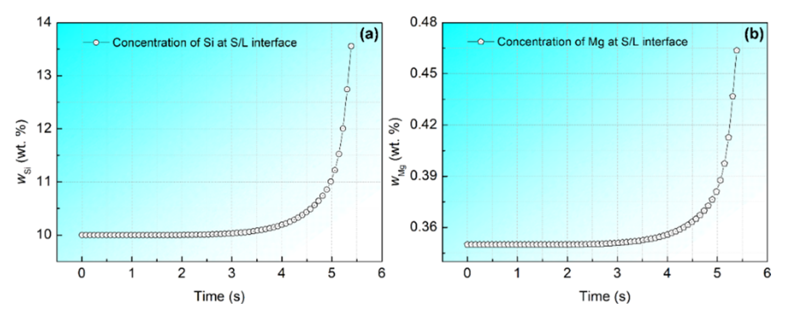
2.1. Solute Distribution

Solute diffusion plays a significant role during dendrite and eutectic growth, and thus, to describe mass transfer of AlSi10Mg ternary alloy, the solute fields of Si and Mg should be calculated separately. For equilibrium solidification, the eutectic concentration is ~12.6 wt.% for Al-Si alloys [9,14], and the solubility of Si in eutectic Al (α-phase) is ~1.6 wt.%, while the solubility of Si in eutectic Si (β-phase) is close to 100% [34]. Considering the mutual diffusion coefficient between elements is much smaller than self-diffusion coefficient, the mutual diffusion process is negligible in the present model. The solute diffusion within the entire domain is calculated based on the following equation:
w ϕ t = D ϕ 2 w ϕ + w α w α 0 f S , α t + w β w β 0 f S , β t
where w is the composition with the subscript φ denoting the liquid, α-phase or β-phase. Dφ is the solute diffusion coefficient in φ phase. wα0 and wβ0 are the solubility of Si element in α-phase and β-phase, respectively. fS,α and fS,β are the solid fraction.

2.2. Interface Growth Kinetics

The growth kinetics are determined by local undercooling in this work, assuming that local thermodynamic equilibrium exists at the interface, caused by the influence of constitutional undercooling and curvature undercooling. Therefore, the local undercooling, ΔT(tn), is defined as the following equation:
Δ T t n = Δ T E + m i w t n w E Γ i K ¯ i t n
where ΔTE is the metastable condition eutectic undercooling. mi is the liquidus slope (i denotes the α-phase or β-phase). w(tn) is the Si concentration of the interfacial cell at certain time tn. w E is the eutectic composition. Γi is the Gibbs–Thomson coefficient of i phase and K ¯ i t n is the mean curvature of the interfacial cell at time tn, which is characterized by:
K ¯ i t n = 1 2 f S , i + j = 1 N f S , i j / N + 1 / Δ x
where f S , i and f S , i j are the solid fraction of i phase in the interfacial cell and its neighboring cells, respectively. N is the number of neighboring cells, which equal 8 in the actual calculations. Δx is the cell size. For a given interfacial cell, the solid fraction of α-phase and β-phase can be calculated separately by the following equations:
Δ f S , α = v t n Δ t n / Δ x
Δ f S , β = cos θ v t n Δ t n / Δ x
where Δtn is the time step, θ is the angle between the growth direction and the linking line, which is between the interfacial cell and the position of nucleus of β-phase, and the growth velocity, v(tn), can be analytically expressed as:
v t n = a Δ T t 2
where a is the growth kinetic coefficient, and the value is 2.9 (μm·s−1·K−2) for non-faceted α-phase, while it is 5.8 (μm·s−1·K−2) for the faceted β-phase [34].

2.3. Nucleation Mechanism

In the past 20 years, several experimental studies [35,36,37] have been performed on the nucleation of Al-Si eutectic alloys. These suggested that the eutectic structure tended to nucleate on the tips of primary dendrite arms in Al-Si alloy, while the eutectic nuclei were always found within the interdendritic liquid regions in Al-Si-x (x represents the other alloying element) alloys. Therefore, the different nucleation mechanism should be taken into account in the current CA model. Based on the achievement of predecessors [34,38,39], a nucleation mechanism is introduced to describe heterogeneous nucleation of AlSi10Mg alloy. For a liquid/α-phase interface cell, if the solute concentration is as high as wLα w E > Δwα, then the liquid/α-phase interface cell will be transferred into a liquid/β-phase interface cell. Therefore, β-phase nucleus is introduced at the concave region of α-phase lamella. Similarly, if the solute concentration of liquid/β-phase interfacial cell is below a critical value, i.e., wLβ w E < Δwβ, then the liquid/β-phase interface cell changes into a liquid/α-phase interface cell, and thus, α-phase nucleus is introduced at the concave region of β-phase lamella. With the nucleation and growth of α-phase and β-phase, eutectic lamellar branching and competitive growth occurs until the effects between solute diffusion and surface energy balance. As per [34], the values of Δwα and Δwβ were chosen to be 0.8 and −1.8, respectively.

2.4. Simulation Parameters and Experimental Methods

Some equivalent thermophysical parameters (such as the density, thermal conductivity and specific heat, etc.) of AlSi10Mg alloy were calculated by the professional metal performance calculation software JmatPro (CnTech Co., Ltd., Version 6.1, Shanghai, China). The other thermodynamic data including the eutectic temperature and composition, solubility and liquidus slope, etc., as well as the kinetic data, for instance, diffusion coefficient, were obtained by an optimized table-look-up approach. The main material properties of AlSi10Mg alloy and simulation parameters used in the current study are summarized in Table 1. It is worth noting that the value of solubility in β-phase was obtained from fitting to the results of the reference [34]. In order to simulate the dendrite and eutectic evolution and illustrate the dependence of microstructure on the solidification conditions, corresponding initial boundary conditions were set to imitate the heat transfer of the SLM melt pool.
The experimental feedstock employed in this work is commercial AlSi10Mg spherical powders, with a range diameter of 20–60 μm (Zhejiang Asia General Soldering and Brazing Material Company, Hangzhou, Zhejiang, China). The samples were produced by an SLM facility (SLM 250 HL, SLM Solutions GmbH, Lübeck, Germany) under the protection of an argon gas atmosphere. The build parameters included an optimal laser beam power of 350 W, laser scanning velocity of 1000 mm/s, layer thickness of 30 μm, and hatch spacing of 60 μm. Samples for microstructure observation were mechanically polished and chemically etched. Characterizations of microstructures were carried out with an optical microscope (OM, Olympus BX51M) and a field-emission scanning electron microscope (SEM, ZEISSULTRA-55) equipped with electron backscatter diffraction (EBSD) detector. EBSD samples were mechanically polished using 0.05 µm silica suspension, and performed at an acceleration voltage of 20 kV, working distance of 17.5 mm, tilt angle of 70° and step size of 0.25 µm.

3. Results and Discussion

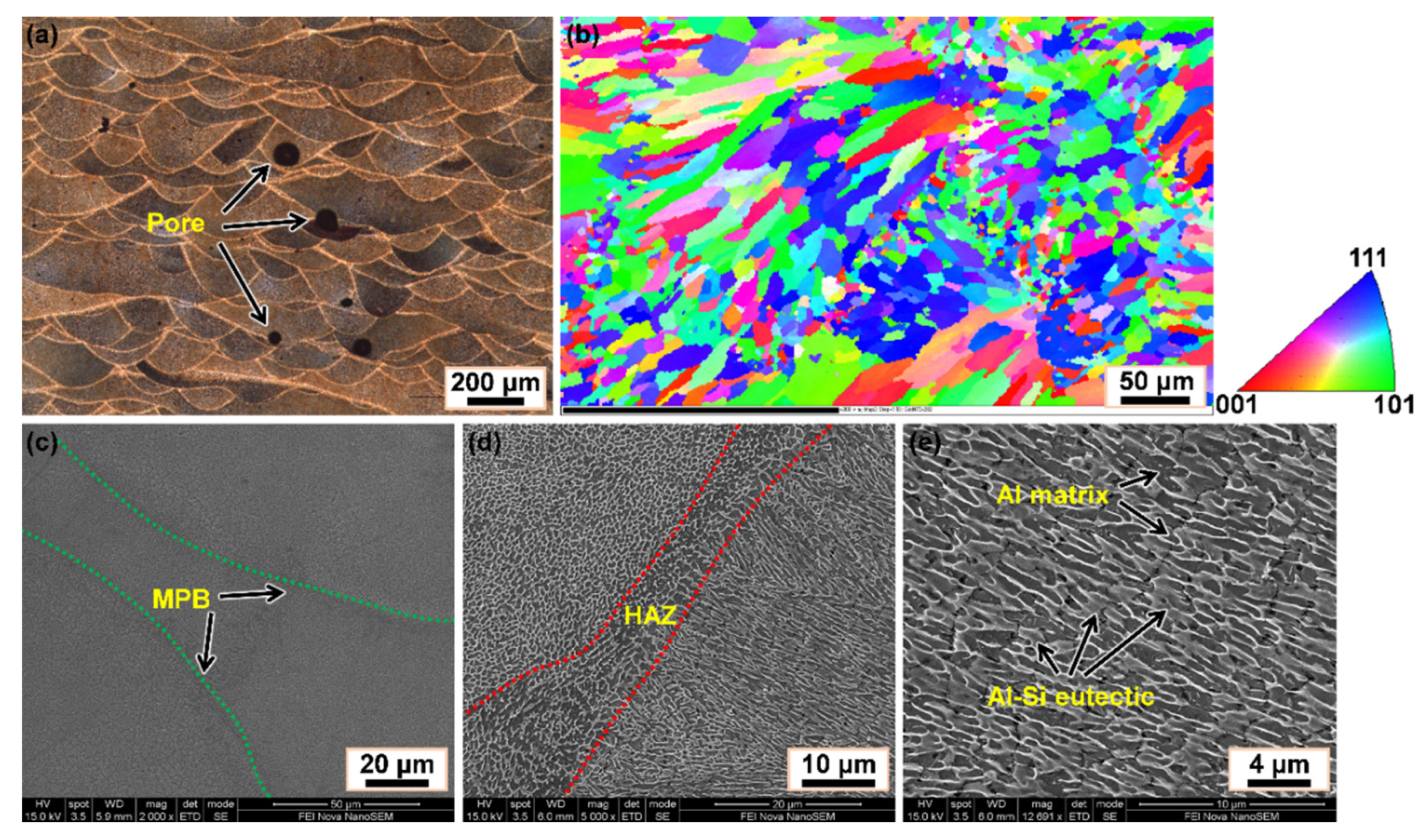
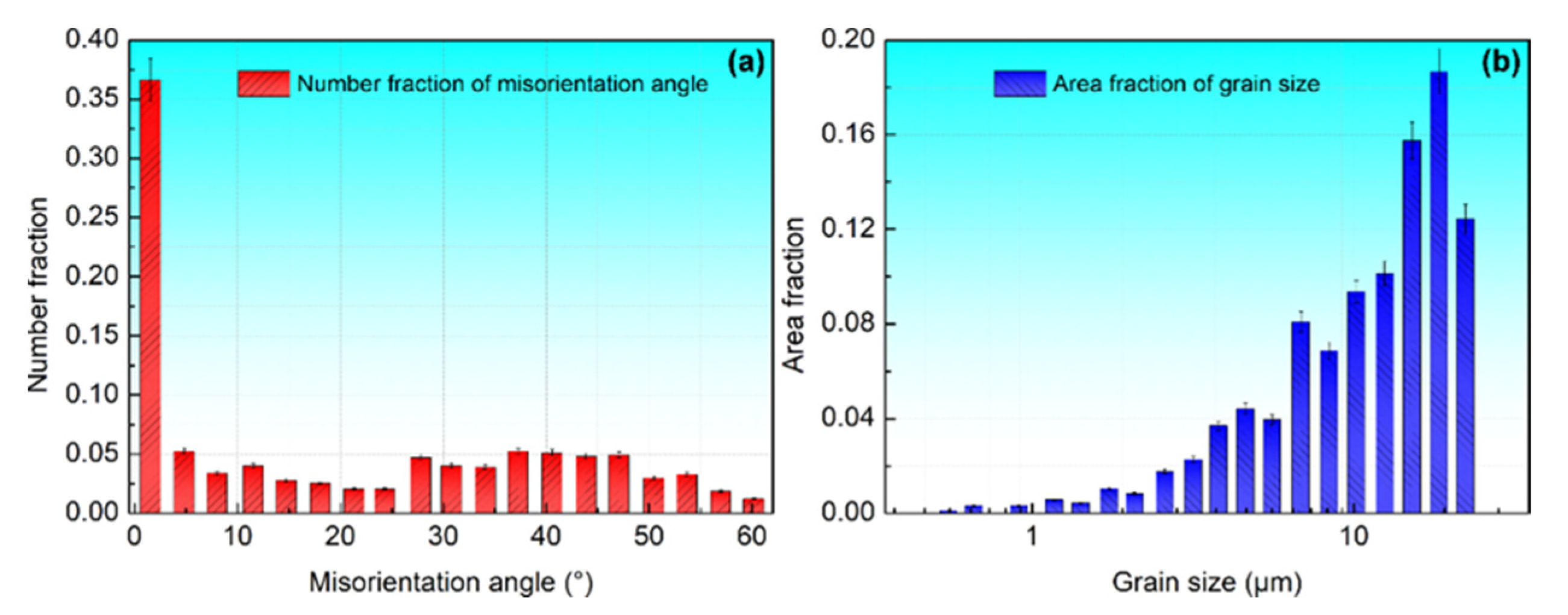
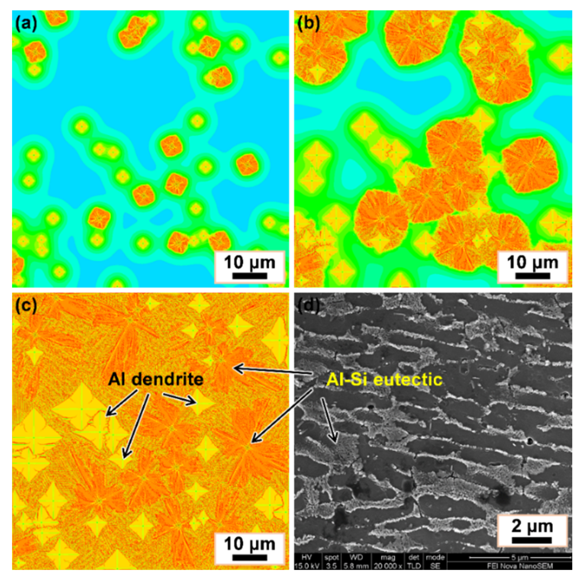
3.1. Experimental Observation of Microstructures

To study both grain size and microstructure morphology, OM, EBSD and SEM observations were performed, and examples of an OM micrograph, an EBSD IPF map and three different magnification SEM micrographs of the SLMed AlSi10Mg alloy are shown in Figure 1. Clearly, the macro-morphology of the as-built sample consists of overlapped melt pools as well as the presence of some pores, and the shape of melting pools was semicircular (Figure 1a). This is due to the progressive laser grating that causes melting and solidification of successive layers of AlSi10Mg alloy. In addition, it can be observed that some pores are located within the melt pools, and the other ones are located at melt pool boundaries (MPBs). These pores are formed due to unmelted powder or insufficient overlap between scan tracks. The EBSD IPF map in Figure 1b shows that the microstructures within individual melt pools are composed mostly of very fine columnar grains growing along the building direction with some equiaxed grains appearing around MPBs. The columnar grains have a mean width of 20 µm and are approximately up to 100 µm in length, while the equiaxed grains have a diameter ranging from 5 to 20 µm. Most of the columnar grains have a preferable <001> orientation, which is considered along scanning direction, while the equiaxed grains present a random crystallographic orientation, resulting in the development of overall texture. For further analyzing the grain characteristics, more detailed statistics of misorientation angle and grain size distribution from the results of EBSD are shown in Figure 2. It can be seen from Figure 2a that ~37% of grains have a misorientation angle less than 5°, which means a preferable <001> orientation along the building direction is dominant. In addition, the fraction of grains with misorientation angle between 28° and 48° is about 35%. The possible reason might be the columnar grains grow deviate from the heat flow direction during the SLM process. The maximum misorientation angle is higher than 60°, which implies the presence of competitive growth along the heat flow direction [9]. Considering the irregular shape of grains, the average equivalent circle diameter of each grain was adopted to evaluate the grain size distribution. The average grain size was mainly from 0.5 to 50 µm (Figure 2b). As reported earlier [9], the grain size was affected by laser power, which in low-laser-power samples is much smaller than that in higher ones. The macro-morphology and texture of grains in SLMed AlSi10Mg alloy were analyzed above from the OM and EBSD results, and a detailed microstructural characterization in the grains is further observed by the SEM micrographs. The melt pool track boundaries can be seen obviously, which were marked by the green dotted lines in Figure 1c. The reason for the discontinuous tracks is that the previously deposited layers have been remelted partially and heat transmission is not uniform, leading to the variations in depth and shape of the melt pool [9]. Across the melt pools, a heat-affected zone (HAZ) with about 5–15 μm in width can be seen in Figure 1d. The HAZ is formed by the heat input of the new layer decomposing of Si from the fine cellular structure of the underlying layer [41]. In HAZ, the fibrous Si network was broken into particles, but the original network can still be traced. In addition, some of the coarsen Si particles could also be seen in HAZ. The micrograph at higher magnification in Figure 1e gives a clear observation that the microstructure of SLMed AlSi10Mg alloy is mainly composed of primary Al phase in darker contrast and Al-Si eutectic phase in relatively lighter contrast distributed in the interdendritic area. According to [9,10] and our previous study [42], the primary Al grain in the semicircular melt pools was made up of typically elongated cell-like/cellular substructures with boundaries of Si-rich regions.

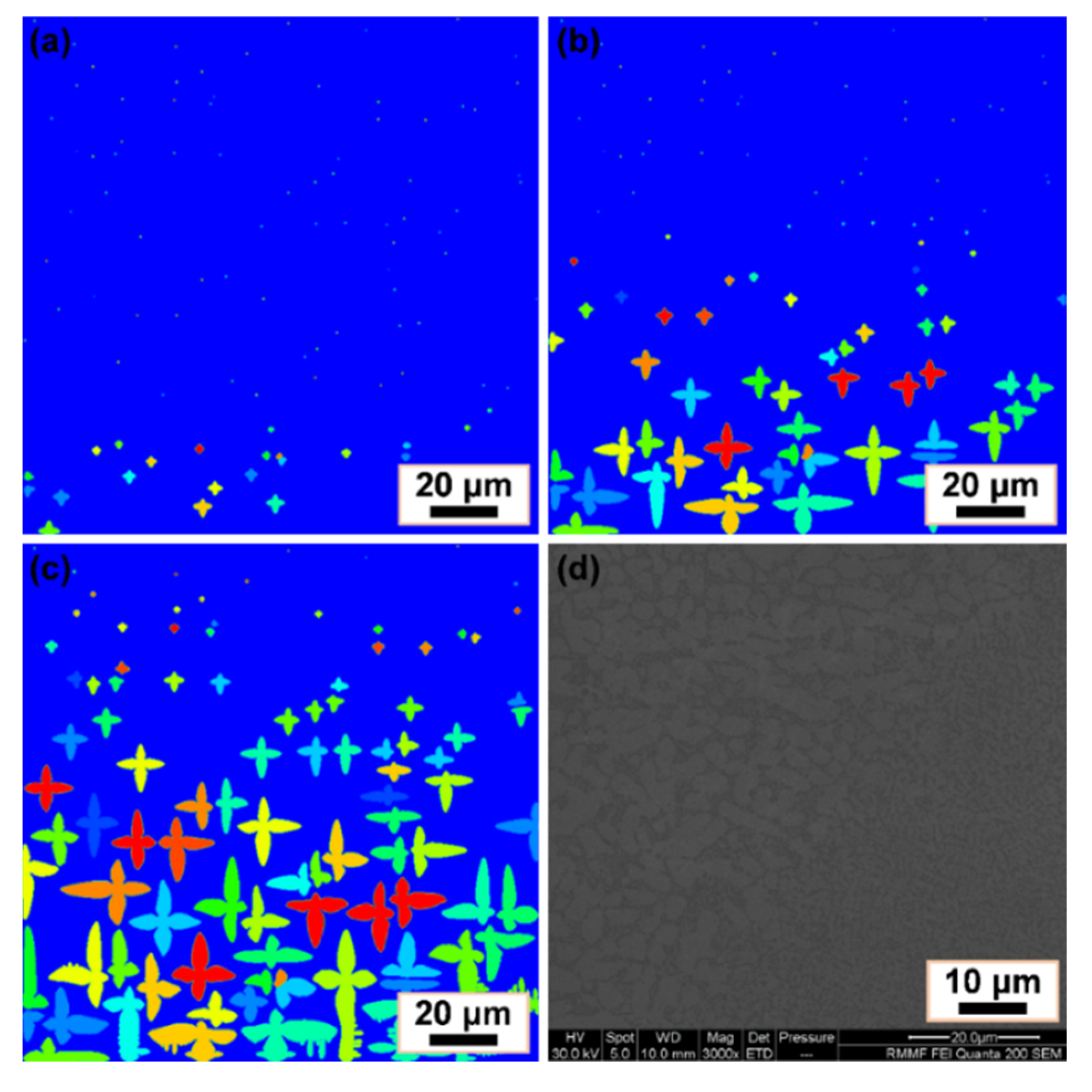
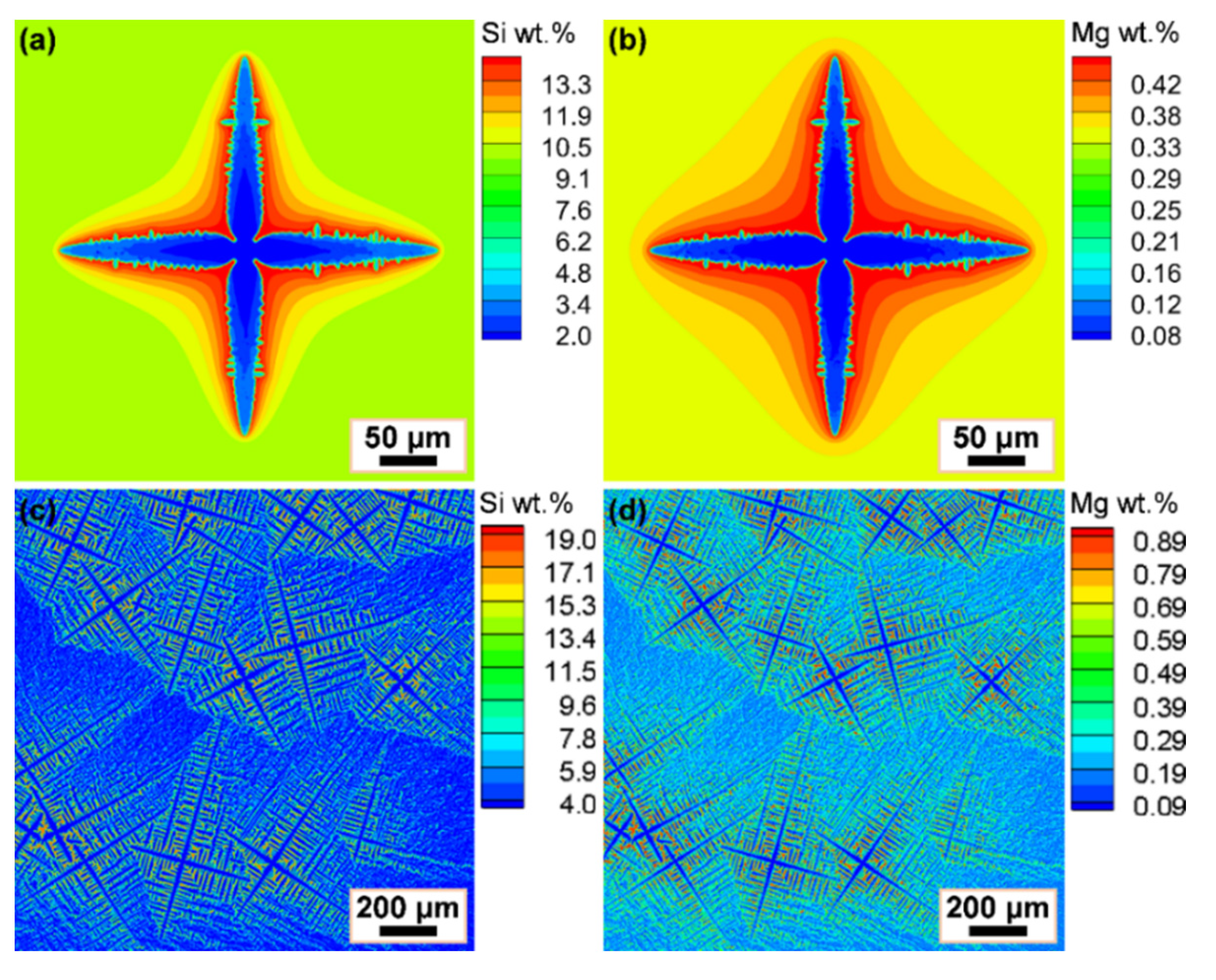
3.2. Dendrite Growth of AlSi10Mg Ternary Alloy

Dendrite is the substructure of primary Al grain in AlSi10Mg alloy, and thus further understanding of dendrite growth and distribution is essential for obtaining the desirable microstructure and improving the performance of the SLMed samples. The comparison of dendrite growth and morphology by simulation and experiment is shown in Figure 3. Dendrite growth simulation was performed in a two-dimensional domain consisting of 100 × 100 cells with a cell size of 2 μm. Prior to simulation, in order to maximize the analogue of the real heat transfer in the melt pool during SLM, some parameters were initialized. Firstly, the temperature of the calculation domain was set to the various gradients with a homogeneous composition. Then, a stochastic nucleation model was adopted, which is a function related to the local undercooling, ΔT(tn), (see our previous research [43] for details). Initially, with the temperature decreasing, an increase in the undercooling and nucleation occurs when the undercooling reaches the critical value. It can be found that nucleation of dendrites preferentially forms at the lower area of the calculation domain, due to the presence of the thermal gradient (Figure 3a). After that, the earlier formed nuclei start growing, and the fourfold symmetry dendrite arms develop along their crystallographic orientations; meanwhile, nuclei are continuously produced from the undercooled melt solution (Figure 3b). In addition, it can be observed that at the early stage, the number and the size of dendrites are relatively small, dendrites are far from each other with less interaction limitation, and thus dendrites can freely grow into fourfold symmetry morphologies along their preferential growth directions. As solidification proceeds, the interaction effects of the solute field between the adjacent dendrites are intensified, the primary trunk of dendrites become coarse accompanied by side branching and the collision of dendrites, hindering free dendrite growth, leading to the coarsening of the dendrite arms and the formation of secondary dendrite arms (Figure 3c). In addition, to observe the dendritic morphology of α-Al, the end of the sample was selected for SEM observation where the eutectic phase had not yet formed, and the sample was simply cleaned without being etched. The SEM micrograph is shown in Figure 3d, and it is worth noting that the dendritic morphology is asymmetric and there are differences between the simulated and experimental results, because of the nonuniform solute distribution in growing tips under the influence of gravity and fluid flow. In addition, at the end of solidification, residual melt solidifies rapidly due to the absence of continuous heat source, and thus, dendrite arms do not have enough time to coarsen.
In order to investigate the influence of solute interactions on dendrite growth, single and multi-equiaxed dendrites of AlSi10Mg alloy were simulated without considering nature and forced convection influence. For single-dendrite cases, the domain was a 200 × 200-cell square with a cell size of 2 μm, and a fixed nucleus was placed in the center of the calculation domain. For multiple-dendrite cases, simulation was performed in a domain of 800 × 800 cells with a cell size of 2 μm, and stochastic nuclei number was assigned in the calculation domain. Figure 4 shows the simulation results of solute distribution and single/multi-equiaxed dendritic morphologies of AlSi10Mg alloy. As can be seen from Figure 4a,b, the dendrite arms develop steadily along the crystallographic orientation and dendritic morphology presents fourfold symmetry. In addition, the solute concentration for both Si and Mg appears accumulated near the dendrite interface because of solute redistribution. Since the solute diffusivity is much smaller than dendrite growth velocity, the solute discharged from the newly solidified solid phase cannot sufficiently diffuse to the bulk liquid. In order to observe the changes of the solute concentration at S/L interface, the solute concentration evolves with the solidification time of Si and Mg is plotted in Figure 5. The statistical results indicate that Si and Mg solute concentration at S/L interface approach a steady state during the initial stage of solidification, and then the values increase significantly. That is because the solute concentration in liquid of the S/L interface cell is greater than the equilibrium value at the S/L interface, and solute will eject into the neighboring liquid. It can be deduced that dendritic tip growth will be inhibited and the steady-state tip-growth velocity decrease dramatically because of the enriched solute at S/L interface and the limitation of the diffusion ability. In addition, the enriched solute around dendrite arms, leading to thin dendrite arms and long and thin tips, especially the constriction phenomenon at the dendritic root. In Figure 4c,d, the solute distribution of Si and Mg elements at the end of solidification is presented, indicating more complicated secondary and tertiary dendrite arm branching. It is obvious that the solutes are significantly enriched in the residual liquid and tip growth sufficiently suppressed. Moreover, the dendritic morphologies are also affected by nucleation location, crystallographic orientation, side branching and interaction among the surrounding dendrites.
As the result of high cooling rate and thermal gradient of SLM, a unique microstructure in the as-built AlSi10Mg sample will be formed. The characteristics of the microstructures are dependent on the thermal gradient (G, K/mm) and the solidification rate (R, mm/s). The ratio of G/R determines the solidification mode, while the value of G × R (i.e., cooling rate, K/s) determines the fineness of the microstructure [8,9,14]. In addition, according to reference [44], the majority of cooling rates during traditional casting are at no more than 20 K/s, while the cooling rates can be up to 103–105 K/s in SLM [10]. Therefore, simulations with different cooling rates were performed to investigate the influence of cooling conditions on dendrite characteristics. Figure 6 represents the simulated dendritic morphologies of AlSi10Mg alloy at cooling rates of 10 K/s, 100 K/s and 1000 K/s, respectively. The calculation domain is divided into 800 × 800 cells with a cell size of 2 μm. It can be observed that the dendrites are refined as the cooling rate increases, and the secondary and tertiary dendrites are more flourishing at the higher cooling rate (Figure 6c), while primary trunks present good growth tendency at the lower cooling rate (Figure 6a). Since the growth velocities of dendrite tips are also affected by the local solute concentration, it can be certainly expectable that the velocities of all dendritic tips commence from the higher values and then drop down to their different stable levels. It is noticed that dendrite growth is significantly affected by the interaction between solute field and the surrounding dendrites under all cooling rates, resulting in severe competitive growth. Clearly, high cooling rate will promote competitive growth and side branching of the secondary or tertiary dendrite arms. Accordingly, once one or more relative larger side branching arms are developed by competitive growth, the small neighboring branches will be sheltered by the outgrown secondary or tertiary dendrite arms. Overall, the complicated dendritic morphologies are believed to be mainly attributable to their nucleation, solute distribution, inherently preferred growth direction, competitive growth, and the different solidification conditions.

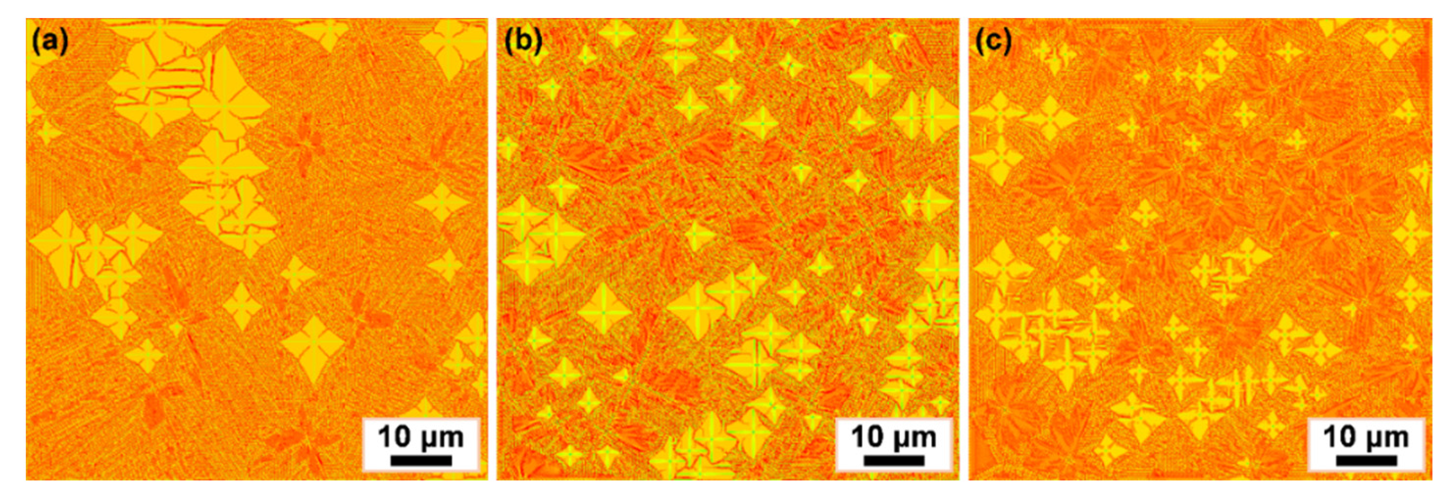
3.3. Simulation of Al-Si Eutectic Evolution

In this section, Al-Si eutectic growth was simulated by the proposed model, and it was compared with the experimental result. Figure 7 shows several simulated frames of the formation of Al-Si eutectic evolution and an SEM micrograph of eutectic morphology. The simulation case was performed in a rectangular domain containing 400 × 400 cells with a cell size of 0.2 μm. Before simulating, the eutectic undercooling ΔTE was set to 10 K, and the initial Si concentration in the melt set to the eutectic composition of 12.6 wt.%. It can be seen from Figure 7a, primary Al dendrites and Al-Si eutectic nuclei are both generated in the melt, which the yellow color in the graph represents the primary Al dendrites, and the orange color donates Al-Si eutectic (including eutectic Al, i.e., α-phase and eutectic Si, i.e., β-phase). As the solidification proceeds, the Al-Si eutectic present a roughly spherical interface, and the growth velocity of Al-Si eutectic is obviously faster than that of primary Al dendrites (Figure 7b). Actually, Si is nonmetallic with directed covalent bonds and tends to grow anisotropically into faceted crystals, while it requires a higher undercooling to drive the grain growth than that for the isotropic primary Al dendrites. However, once the required conditions of concentration and temperature are both reached, the eutectic Si then begins to nucleate and grow rapidly, especially for those eutectic Si nuclei attached to the surface of primary Al dendrites [45]. During the growth of Al-Si eutectic, α-phase will reject excess Si solute due to solute redistribution while β-phase will absorb amounts of solute from the surrounding liquid. Figure 7c displays the final solidified microstructure, including the primary Al dendrites, Al-Si eutectic and entangled Si precipitates. Apparently, few eutectic Si eventually form petaliform Al-Si eutectic, while most of the eutectic Si networks are broken into fine Si particles that are dispersed more uniformly in the Al matrix. In the highest-resolution SEM image (Figure 7d), the same microstructure characteristics were observed in that the dark-gray cellular features are primary Al matrix decorated with light-gray Si networks. When observing the eutectic structure, the α-Al dendrites were removed by chemical etching. The experimental results presented good agreement with the simulation, which indicates that the proposed model can successfully reproduce both dendrite and eutectic microstructures.
To investigate the effect of undercooling on eutectic morphology, three other simulation cases were carried out under the various eutectic undercooling. Figure 8 shows the morphologies of Al-Si eutectic microstructures after being fully solidified with the eutectic undercooling of 5 K, 15 K and 20 K. It can be observed that the primary Al dendrites and Al-Si eutectic have greatly changed with the eutectic undercooling increasing. The primary Al dendrites are relatively large at the low eutectic undercooling, while the number of petaliform Al-Si eutectic is fewer and small (Figure 8a). The reason lies in the interface growth velocity being relatively slow under a low eutectic undercooling, solute diffusion is sufficient and it is difficult for the solute concentration to reach the critical nucleation concentration of Si phase, and thus the primary Al dendrites have enough time to grow larger. In Figure 8b, the size of primary Al dendrites is evidently reduced, while both size and quantity of Al-Si eutectic increase as the eutectic undercooling increases to 15 K. Under a higher eutectic undercooling, the insufficient solute diffusion at the interface front makes it easier to reach the critical nucleation condition for Si phase, and thus the Al-Si eutectic is relatively easy to produce. It can be seen that the size of primary Al dendrites further reduces, and Al-Si eutectic become finer lamellar morphology (Figure 8c). The results indicate that Al-Si eutectic morphologies are sensitive to the eutectic undercooling, i.e., the higher the eutectic undercooling, the easier to form finer Al-Si eutectic.

4. Conclusions

In this work, a comprehensive model was established to investigate the microstructure evolution during SLM of AlSi10Mg alloy. Both the dendrite and eutectic growth were simulated and corresponding experiments performed to verify the accuracy of the proposed model. The main conclusions are as follows:
(1)
An integrated primary dendrite and eutectic evolution model based on the CA-FD method, taking account of solute distribution, growth kinetics and nucleation mechanism, was developed. The proposed model would be helpful for describing the time-dependent dendrite and eutectic growth during the nonequilibrium solidification process and understanding the microstructure evolution of Al-Si system alloys. However, the presented model is also preliminary and simplified, and there are some restrictions, such as not considering the influence of fluid flow and gravity, which need to be further refined in the future work.
(2)
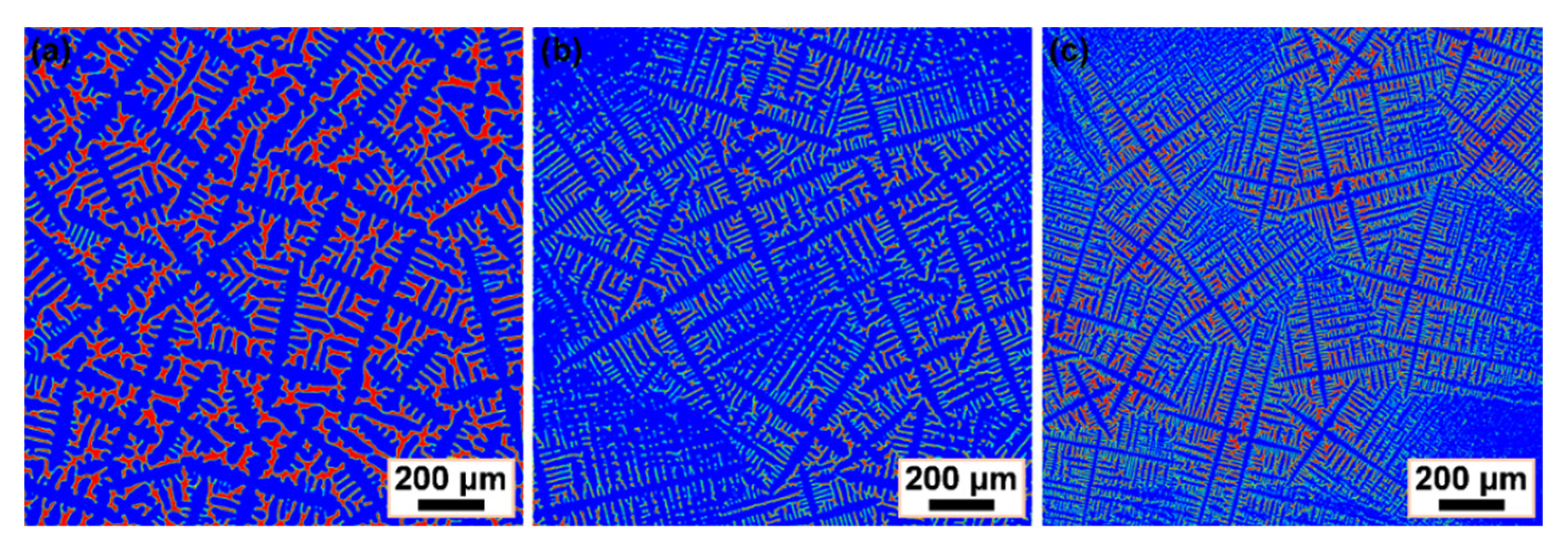
Dendrite growth of AlSi10Mg alloy was simulated by the proposed model and various gradients initialized to imitate real heat transfer in the melt pool during SLM. The experimental dendrites obtained by SEM presented good agreement with the simulation. Single and multi-equiaxed dendritic morphologies of AlSi10Mg ternary alloy were simulated, and it was found that solute diffusion had a significant influence on dendrite growth. The influence of cooling rate on dendrite characteristics was further investigated, and the results indicated that dendrites were refined with the increasing of the cooling rates.
(3)
The Al-Si eutectic evolution in AlSi10Mg alloy was simulated, and corresponding experimental validation was also carried out, and both of them agreed reasonably well. Finally, the proposed model was applied to investigate the effect of undercooling on eutectic morphology, and simulations with the eutectic undercooling of 5 K, 15 K and 20 K were performed. The simulated results revealed that Al-Si eutectic morphologies were sensitive to the eutectic undercooling such that a higher eutectic undercooling can refine the eutectic microstructure.

Author Contributions

Conceptualization, Q.X. and Z.W.; experiments, Z.X. and S.L.; methodology, Q.X. and Z.W.; modeling and simulation, X.Y. (Xuewei Yan) and X.Y. (Xuemei Yang); investigation, resources and data curation, G.T. and D.S.; writing—original draft Preparation, X.Y. (Xuewei Yan); writing—review and editing, S.L., Z.X. and Q.X. All authors have read and agreed to the published version of the manuscript.

Funding

This research was funded by the Program for Science and Technology Innovation Talents in Universities of Henan Province (22HASTIT031) and the National Natural Science Foundation of China (51904276 and 51975539).

Institutional Review Board Statement

Not applicable.

Informed Consent Statement

Not applicable.

Data Availability Statement

The data presented in this work are available on request from the corresponding authors.

Conflicts of Interest

The authors declare no conflict of interest.

References

  1. Starke, E.A., Jr.; Staley, J.T. Application of modern aluminum alloys to aircraft. Prog. Aerosp. Sci. 1996, 32, 131–172. [Google Scholar] [CrossRef]
  2. Miller, W.S.; Zhuang, L.; Bottema, J.; Wittebrood, A.J.; De Smet, P.; Haszler, A.; Vieregge, A. Recent development in aluminium alloys for the automotive industry. Mater. Sci. Eng. A 2000, 280, 37–49. [Google Scholar] [CrossRef]
  3. Dursun, T.; Soutis, C. Recent developments in advanced aircraft aluminium alloys. Mater. Des. 2014, 56, 862–871. [Google Scholar] [CrossRef]
  4. Javidani, M.; Larouche, D. Application of cast Al-Si alloys in internal combustion engine components. Int. Mater. Rev. 2014, 59, 132–158. [Google Scholar] [CrossRef]
  5. Zhang, X.; Chen, Y.; Hu, J. Recent advances in the development of aerospace materials. Prog. Aerosp. Sci. 2018, 97, 22–34. [Google Scholar] [CrossRef]
  6. Kempen, K.; Thijs, L.; Van Humbeeck, J.; Kruth, J.P. Processing AlSi10Mg by selective laser melting: Parameter optimisation and material characterization. Mater. Sci. Technol. 2015, 31, 917–923. [Google Scholar] [CrossRef]
  7. Paoletti, C.; Santecchia, E.; Cabibbo, M.; Cerri, E.; Spigarelli, S. Modelling the creep behavior of an AlSi10Mg alloy produced by additive manufacturing. Mater. Sci. Eng. A 2021, 799, 140138. [Google Scholar] [CrossRef]
  8. Li, W.; Li, S.; Liu, J.; Zhang, A.; Zhou, Y.; Wei, Q.; Yan, C.; Shi, Y. Effect of heat treatment on AlSi10Mg alloy fabricated by selective laser melting: Microstructure evolution, mechanical properties and fracture mechanism. Mater. Sci. Eng. A 2016, 663, 116–125. [Google Scholar] [CrossRef]
  9. Liu, X.; Zhao, C.; Zhou, X.; Shen, Z.; Liu, W. Microstructure of selective laser melted AlSi10Mg alloy. Mater. Des. 2019, 168, 107677. [Google Scholar] [CrossRef]
  10. Wu, J.; Wang, X.; Wang, W.; Attallah, M.M.; Loretto, M.H. Microstructure and strength of selectively laser melted AlSi10Mg. Acta Mater. 2016, 117, 311–320. [Google Scholar] [CrossRef]
  11. Dasgupta, R. Property improvement in Al-Si alloys through rapid solidification processing. J. Mater. Process. Technol. 1997, 72, 380–384. [Google Scholar] [CrossRef]
  12. Shabestari, S.G.; Moemeni, H. Effect of copper and solidification conditions on the microstructure and mechanical properties of Al-Si-Mg alloys. J. Mater. Process. Technol. 2004, 153–154, 193–198. [Google Scholar] [CrossRef]
  13. Reed, N.; Wang, W.; Essa, K.; Attallah, M.M. Selective laser melting of AlSi10Mg alloy: Process optimization and mechanical properties development. Mater. Des. 2015, 65, 417–424. [Google Scholar] [CrossRef] [Green Version]
  14. Guo, M.; Sun, M.; Huang, J.; Pang, S. A comparative study on the microstructures and mechanical properties of Al-10Si-0.5Mg alloys prepared under different conditions. Metals 2022, 142, 2010142. [Google Scholar] [CrossRef]
  15. Martin, J.H.; Yahata, B.D.; Hundley, J.M.; Mayer, J.A.; Schaedler, T.A.; Pollock, T.M. 3D printing of high-strength aluminium alloys. Nature 2017, 549, 365–369. [Google Scholar] [CrossRef]
  16. Panwisawas, C.; Tang, Y.T.; Reed, R.C. Metal 3D printing as a disruptive technology for superalloys. Nat. Commun. 2020, 11, 2327. [Google Scholar] [CrossRef] [PubMed]
  17. Zinoviev, A.; Zinovieva, O.; Ploshikhin, V.; Romanova, V.; Balokhonov, R. Evolution of grain structure during laser additive manufacturing. Simulation by a cellular automata method. Mater. Des. 2016, 106, 321–329. [Google Scholar] [CrossRef]
  18. Lian, Y.; Gan, Z.; Yu, C.; Kats, D.; Liu, W.K.; Wagner, G.J. A cellular automaton finite volume method for microstructure evolution during additive manufacturing. Mater. Des. 2019, 169, 107672. [Google Scholar] [CrossRef]
  19. Xiong, F.; Huang, C.; Kafka, O.L.; Lian, Y.; Yan, W.; Chen, M.; Fang, D. Grain growth prediction in selective electron beam melting of Ti-6Al-4V with a cellular automaton method. Mater. Des. 2021, 199, 109410. [Google Scholar] [CrossRef]
  20. Sahoo, S.; Chou, K. Phase-field simulation of microstructure evolution of Ti-6Al-4V in electron beam additive manufacturing process. Addit. Manuf. 2016, 9, 14–24. [Google Scholar] [CrossRef]
  21. Lu, L.; Sridhar, N.; Zhang, Y. Phase field simulation of powder bed-based additive manufacturing. Acta Mater. 2018, 144, 801–809. [Google Scholar] [CrossRef]
  22. Yang, M.; Wang, L.; Yan, W. Phase-field modeling of grain evolutions in additive manufacturing from nucleation, growth, to coarsening. Npj Comput. Mater. 2021, 7, 56. [Google Scholar] [CrossRef]
  23. Chadwick, A.F.; Voorhees, P.W. The development of grain structure during additive manufacturing. Acta Mater. 2021, 211, 116862. [Google Scholar] [CrossRef]
  24. Rai, A.; Markl, M.; Körner, C. A coupled cellular automaton-lattice boltzmann model for grain structure simulation during additive manufacturing. Comput. Mater. Sci. 2016, 124, 37–48. [Google Scholar] [CrossRef]
  25. Akram, J.; Chalavadi, P.; Pal, D.; Stucker, B. Understanding grain evolution in additive manufacturing through modeling. Addit. Manuf. 2018, 21, 255–268. [Google Scholar] [CrossRef]
  26. Zinovieva, O.; Zinoviev, A.; Ploshikhin, V. Three-dimensional modeling of the microstructure evolution during metal additive manufacturing. Comput. Mater. Sci. 2018, 141, 207–220. [Google Scholar] [CrossRef]
  27. Lian, Y.; Lin, S.; Yan, W.; Liu, W.K.; Wagner, G.J. A parallelized three-dimensional cellular automaton model for grain growth during additive manufacturing. Comput. Mech. 2018, 61, 543–558. [Google Scholar] [CrossRef]
  28. Shi, R.; Khairallah, S.A.; Roehling, T.T.; Heo, T.W.; McKeown, J.T.; Matthews, M.J. Microstructural control in metal laser powder bed fusion additive manufacturing using laser beam shaping strategy. Acta Mater. 2020, 184, 284–305. [Google Scholar] [CrossRef]
  29. Mohebbi, M.S.; Ploshikhin, V. Implementation of nucleation in cellular automaton simulation of microstructural evolution during additive manufacturing of Al alloys. Addit. Manuf. 2020, 36, 101726. [Google Scholar] [CrossRef]
  30. Rappaz, M.; Gandin, C.A. Probabilistic modelling of microstructure formation in solidification processes. Acta Metall. Mater. 1993, 41, 345–360. [Google Scholar] [CrossRef]
  31. Wang, W.; Lee, P.D.; McLean, M. A model of solidification microstructures in nickel-based superalloys: Predicting primary dendrite spacing selection. Acta Mater. 2003, 51, 2971–2987. [Google Scholar] [CrossRef]
  32. Yan, X.; Xu, Q.; Liu, B. Numerical simulation of dendrite growth in nickel-based superalloy and validated by in-situ observation using high temperature confocal laser scanning microscopy. J. Cryst. Growth 2017, 479, 22–33. [Google Scholar] [CrossRef]
  33. Bayat, M.; Dong, W.; Thorborg, J.; To, A.C.; Hattel, J.H. A review of multi-scale and multi-physics simulations of metal additive manufacturing processes with focus on modeling strategies. Addit. Manuf. 2021, 47, 102278. [Google Scholar] [CrossRef]
  34. Chen, R.; Xu, Q.; Liu, B. Modeling of aluminum-silicon irregular eutectic growth by cellular automaton model. China Foundry 2016, 13, 114–122. [Google Scholar] [CrossRef] [Green Version]
  35. Dahle, A.K.; Nogita, K.; Zindel, J.W.; Mcdonald, S.D.; Hogan, L.M. Eutectic nucleation and growth in hypoeutectic Al-Si alloys at different strontium levels. Metall. Mater. Trans. 2001, 32, 949–960. [Google Scholar] [CrossRef]
  36. Nafisi, S.; Ghomashchi, R.; Vali, H. Eutectic nucleation in hypoeutectic Al-Si alloys. Mater. Charact. 2008, 59, 1466–1473. [Google Scholar] [CrossRef]
  37. Sun, Y.; Pang, S.; Liu, X.; Yang, Z.; Sun, G. Nucleation and growth of eutectic cell in hypoeutectic Al-Si alloy. Trans. Nonferr. Metal. Soc. 2011, 21, 2186–2191. [Google Scholar] [CrossRef]
  38. Zhu, M.F.; Hong, C.P. Modeling of microstructure evolution in regular eutectic growth. Phys. Rev. B 2002, 66, 155428. [Google Scholar] [CrossRef]
  39. Xiong, S.; Wu, M. Experimental and modeling studies of the lamellar eutectic growth of Mg-Al alloy. Metall. Mater. Trans. A 2012, 43, 208–218. [Google Scholar] [CrossRef]
  40. Ye, H. An overview of the development of Al-Si-alloy based material for engine applications. J. Mater. Eng. Perform. 2003, 12, 288–297. [Google Scholar] [CrossRef]
  41. Paul, M.J.; Liu, Q.; Best, J.P.; Li, X.P.; Kruzic, J.J.; Ramamurty, U.; Gludovatz, B. Fracture resistance of AlSi10Mg fabricated by laser powder bed fusion. Acta Mater. 2021, 211, 116869. [Google Scholar] [CrossRef]
  42. Xiong, Z.; Liu, S.; Li, S.; Shi, Y.; Yang, Y.; Misra, R.D.K. Role of melt pool boundary condition in determining the mechanical properties of selective laser melting AlSi10Mg alloy. Mater. Sci. Eng. A 2019, 740–741, 148–156. [Google Scholar] [CrossRef]
  43. Yan, X.; Xu, Q.; Tian, G.; Liu, Q.; Hou, J.; Liu, B. Multi-scale modeling of liquid-metal cooling directional solidification and solidification behavior of nickel-based superalloy casting. J. Mater. Sci. Technol. 2021, 67, 36–49. [Google Scholar] [CrossRef]
  44. Chen, R.; Xu, Q.; Liu, B. Cellular automaton simulation of three-dimensional dendrite growth in Al-7Si-Mg ternary aluminum alloys. Comput. Mater. Sci. 2015, 105, 90–100. [Google Scholar] [CrossRef] [Green Version]
  45. Ao, X.; Xia, H.; Liu, J.; He, Q.; Lin, S. A numerical study of irregular eutectic in Al-Si alloys under a large undercooling. Comput. Mater. Sci. 2021, 186, 110049. [Google Scholar] [CrossRef]
Figure 1. Microstructures of the SLMed AlSi10Mg alloy: (a) optical micrograph; (b) EBSD IPF map; (ce) SEM micrographs in different magnification. (Note: the dotted lines in (c) represent the melt pool boundary (MPB), while the heat-affected zone (HAZ) in (d) is drawn between the two dashed lines).
Metals 12 01711 g001
Figure 2. (a) Misorientation angle and (b) grain size distribution of the SLMed AlSi10Mg alloy.
Metals 12 01711 g002
Figure 3. Simulation of dendrite growth at different times and experimental results: (a) t = 1.6 s; (b) t = 4.2 s; (c) t = 7.8 s; (d) SEM micrograph of dendritic morphology.
Metals 12 01711 g003
Figure 4. Simulated solute distribution and single/multiequiaxed dendritic morphologies of AlSi10Mg alloy: (a,c) Si solute concentration fields; (b,d) Mg solute concentration fields.
Metals 12 01711 g004
Figure 5. Solute concentration at S/L interface evolves with solidification time: (a) Si solute concentration; (b) Mg solute concentration.
Metals 12 01711 g005
Figure 6. Simulated dendritic morphologies of AlSi10Mg alloy under different cooling rates: (a) 10 K/s; (b) 100 K/s; (c) 1000 K/s.
Metals 12 01711 g006
Figure 7. Simulation results of Al-Si eutectic evolution with a eutectic undercooling ΔTe = 10 K for various times and experimental result: (a) t = 0.5 s; (b) t = 1 s; (c) t = 2.2 s; (d) SEM micrograph of eutectic morphology.
Metals 12 01711 g007
Figure 8. Simulation results of Al-Si eutectic morphologies under different eutectic undercooling conditions: (a) ΔTe = 5 K; (b) ΔTe = 15 K; (c) ΔTe = 20 K.
Metals 12 01711 g008
Table 1. Material properties and simulation parameters of AlSi10Mg alloy.
Parameter (Unit)ValueReference
Liquidus temperature TL (K)873[29]
Eutectic temperature TE (K)850[40]
Eutectic composition wE (wt.%)12.6[40]
Solubility in α-phase wα0 (wt.%)1.65[34]
Solubility in β-phase wβ0 (wt.%)77.5[34]
Liquidus slope of α-phase mα (K/wt.%)−6.83[29]
Liquidus slope of β-phase mβ (K/wt.%)17.5[34]
Liquid diffusion coefficient DL (m2/s)2.4 × 10−9[29]
Solid diffusion coefficient DS (m2/s)3.0 × 10−12[34]
Gibbs–Thomson coefficient of α-phase Γα (m·K)2.4 × 10⁻⁷[29]
Gibbs–Thomson coefficient of β-phase Γβ (m·K)1.7 × 10⁻⁷[34]
Publisher’s Note: MDPI stays neutral with regard to jurisdictional claims in published maps and institutional affiliations.

