
Air-Hardening Die-Forged Con-Rods—Achievable Mechanical Properties of Bainitic and Martensitic Concepts

Abstract
:1. Introduction
2. Materials and Methods
3. Results
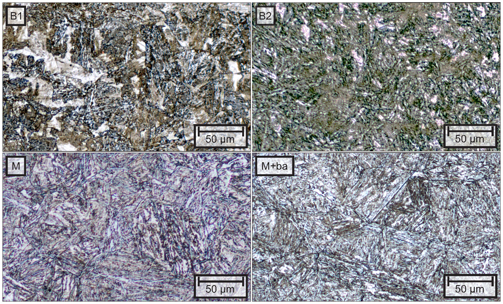
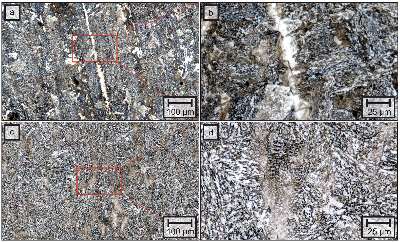
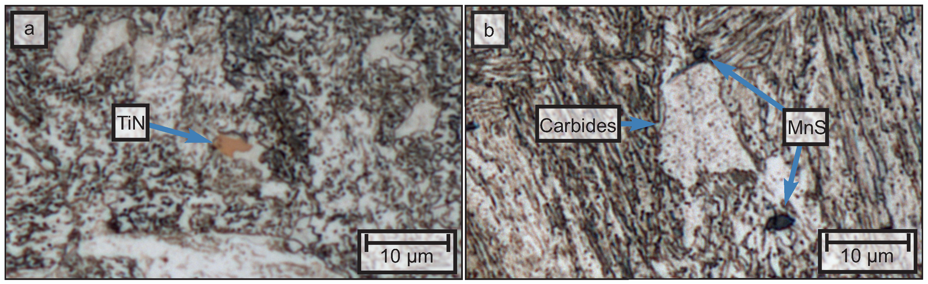
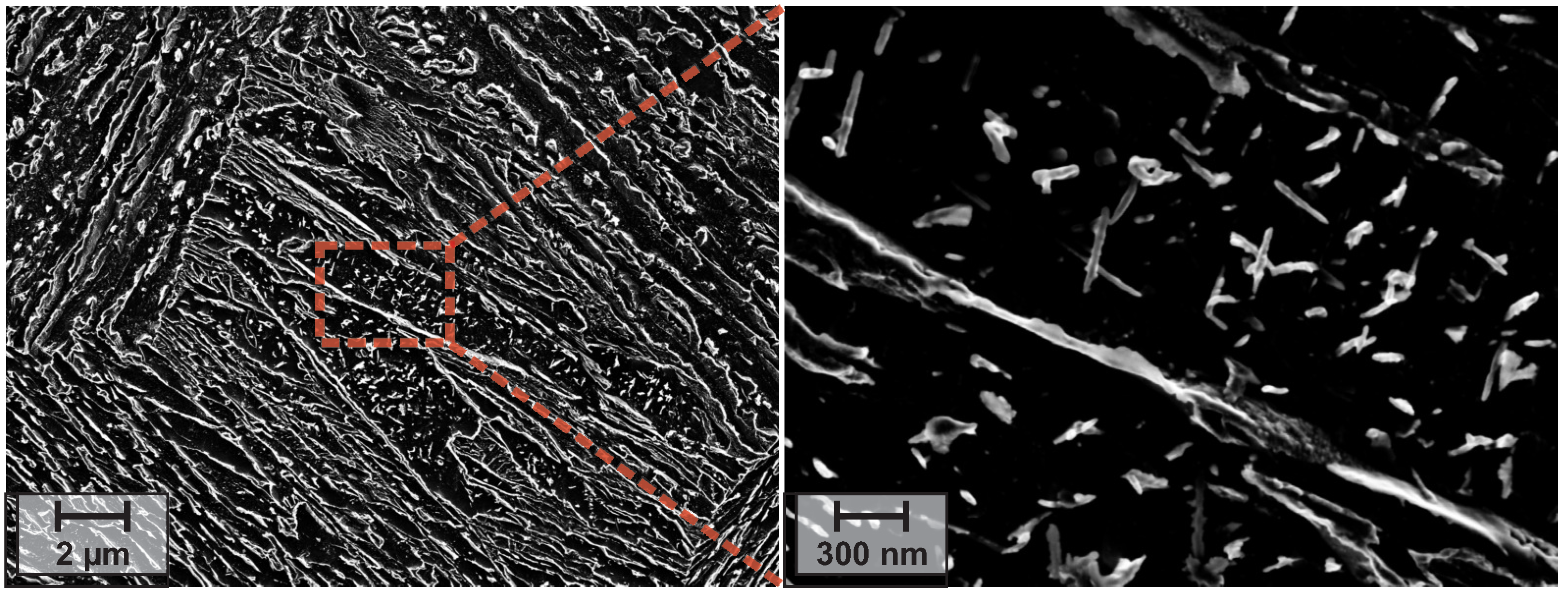
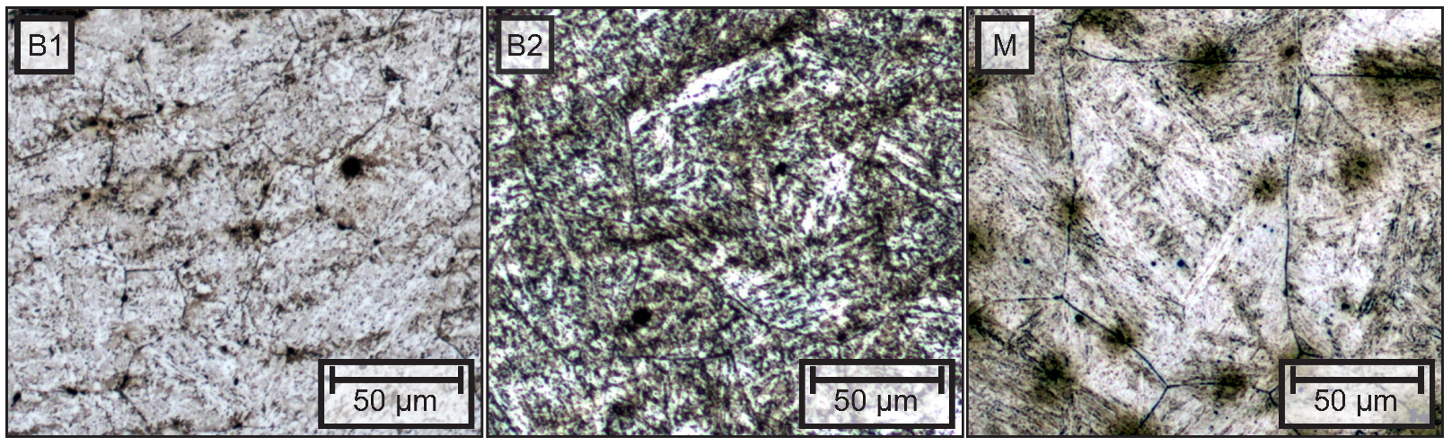
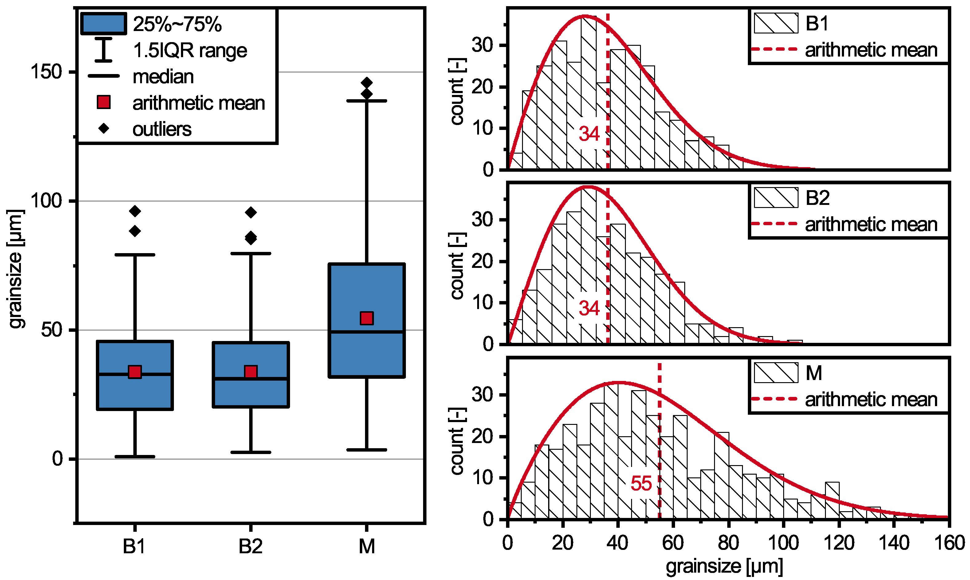
3.1. Microstructure
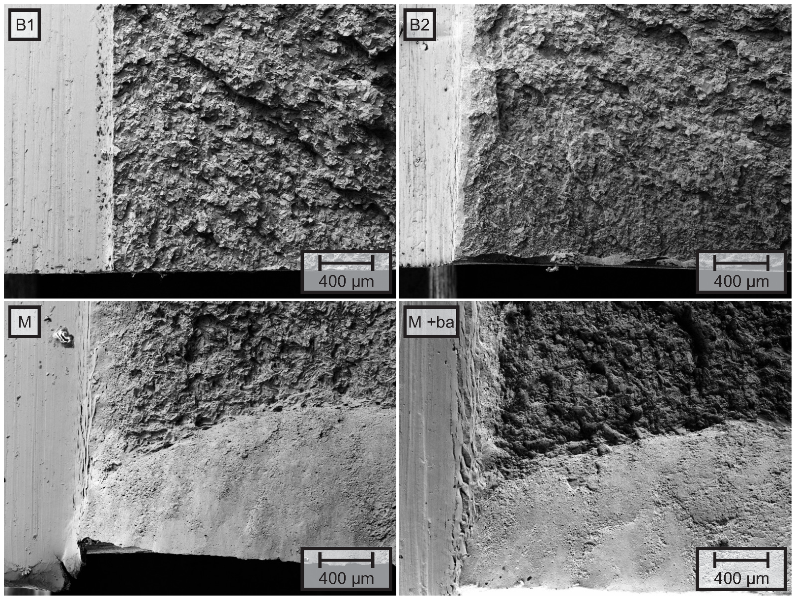
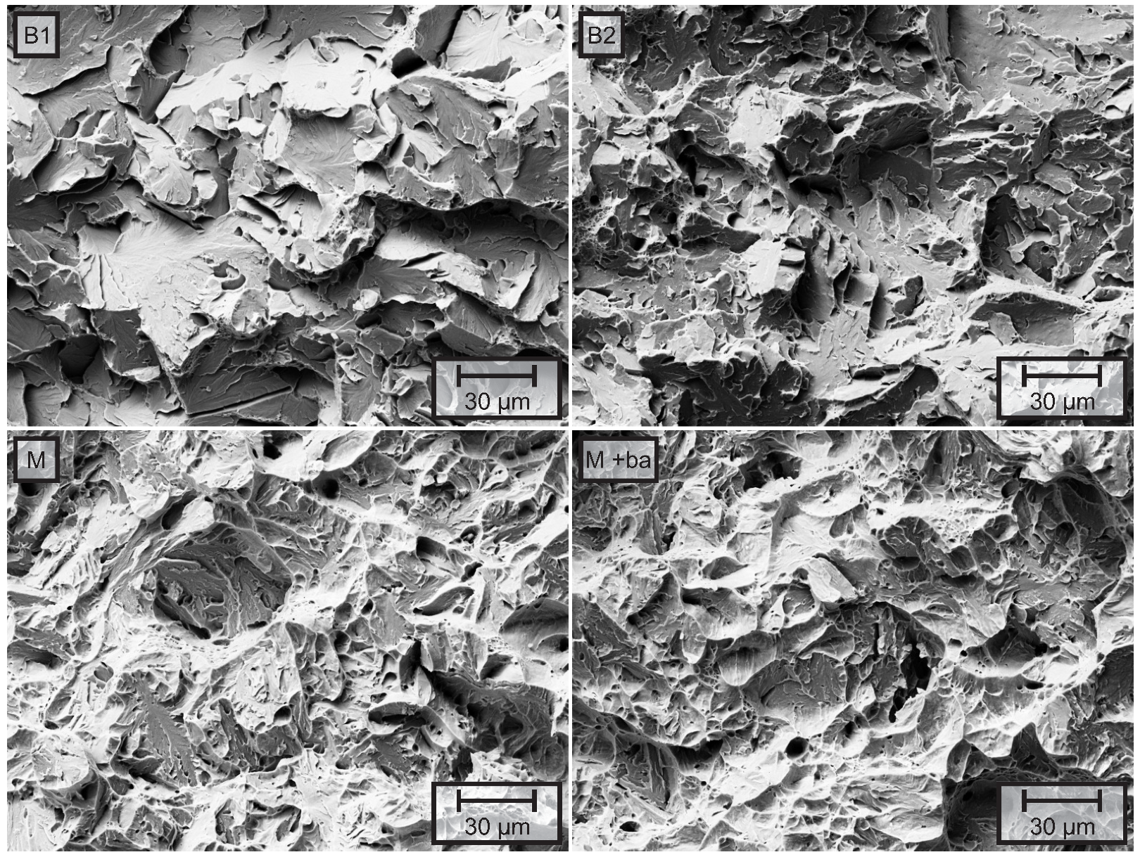
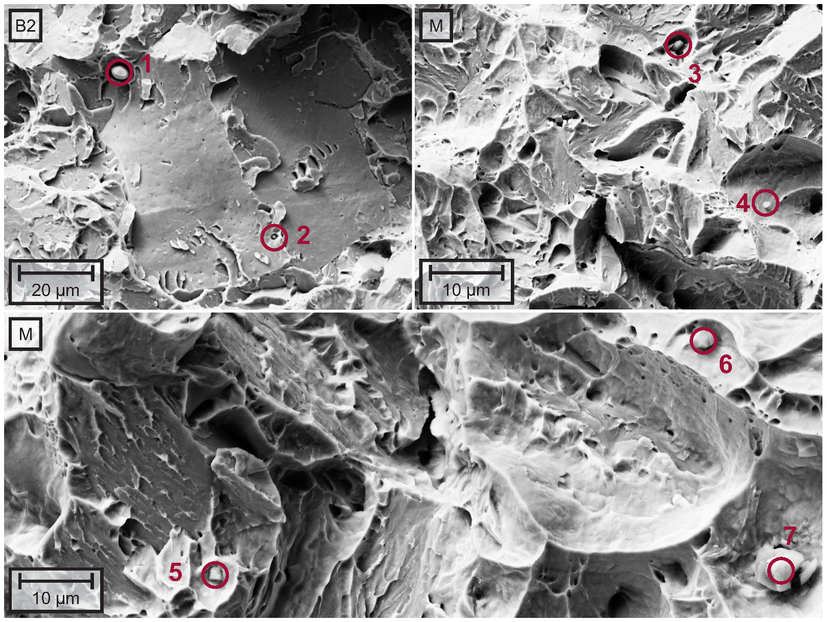
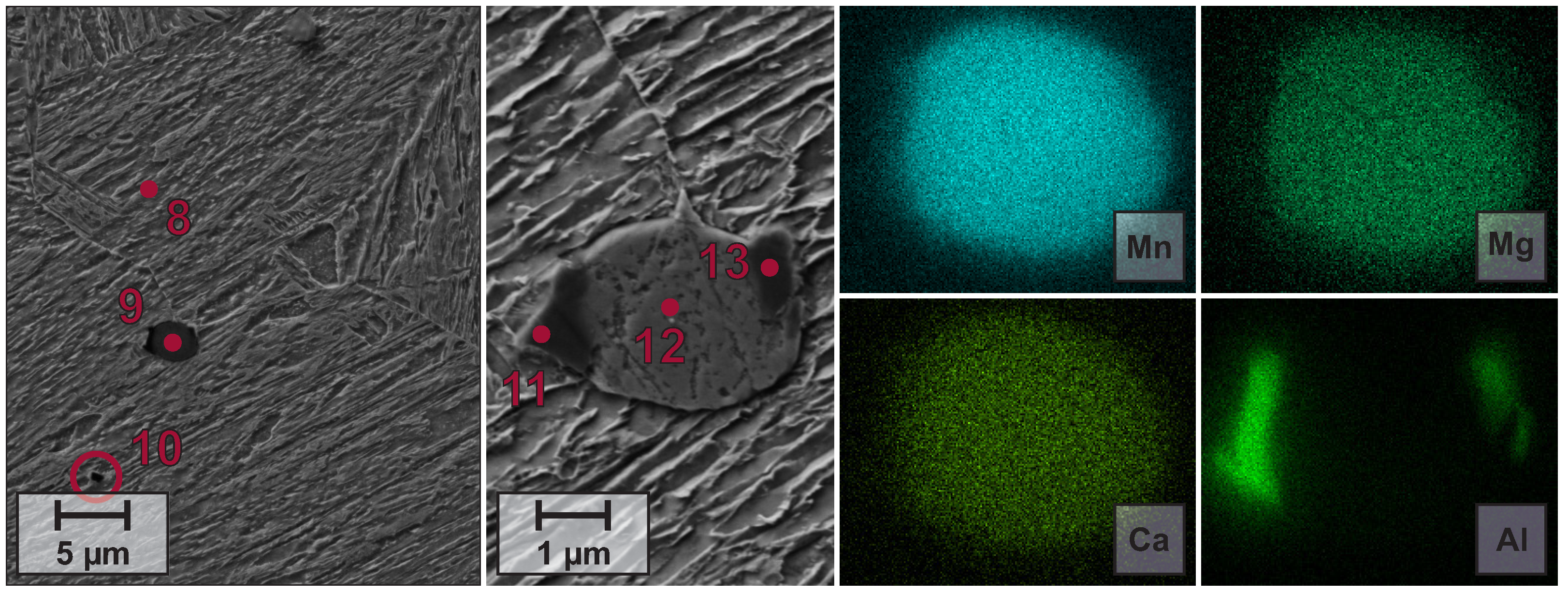
3.2. Fracture Surfaces
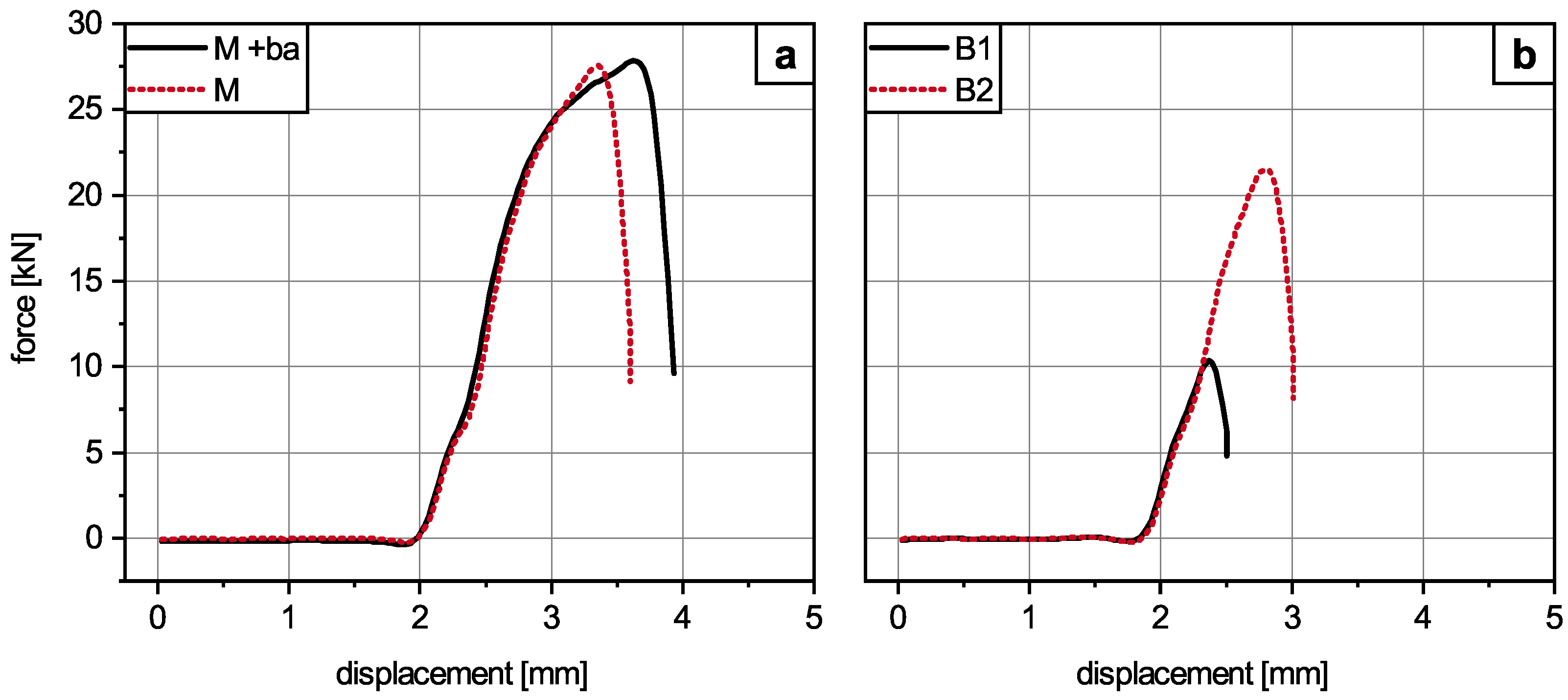
3.3. Mechanical Properties
4. Discussion
5. Conclusions
- The presented steels show good balances of strength and ductility in the air-hardened condition, which enables the substitution of other standard steel grades.
- The CO2-footprint of forged components can be reduced by lightweighting or shortening the heat treatment through the utilization of new air-hardening materials.
- The combination of impact toughness and yield strength is suitable for con-rod production in the case of the bainitic steels, while final confirmation has to be made for the martensitic steel.
- A comparison of the bainitic grades reveals that the 19MnCrMo7-6 steel achieves comparable strength but higher elongations and impact toughness than the 35MnCrB6-4 steel. The differences in mechanical properties can be explained by the differences in the bainite morphology.
Author Contributions
Funding
Institutional Review Board Statement
Informed Consent Statement
Data Availability Statement
Conflicts of Interest
References
- Bleck, W.; Bambach, M.; Wirths, V.; Stieben, A. Microalloyed Engineering Steels with Improved Performance—An Overview. HTM J. Heat Treat. Mater. 2017, 72, 346–354. [Google Scholar] [CrossRef]
- Wirths, V.; Wagener, R.; Bleck, W.; Melz, T. Bainitic Forging Steels for Cyclic Loading. Adv. Mater. Res. 2014, 922, 813–818. [Google Scholar] [CrossRef]
- Sugimoto, K.I.; Sato, S.H.; Kobayashi, J.; Srivastava, A.K. Effects of Cr and Mo on Mechanical Properties of Hot-Forged Medium Carbon TRIP-Aided Bainitic Ferrite Steels. Metals 2019, 9, 1066. [Google Scholar] [CrossRef] [Green Version]
- Hojo, T.; Kobayashi, J.; Sugimoto, K.i.; Nagasaka, A.; Akiyama, E. Effects of Alloying Elements Addition on Delayed Fracture Properties of Ultra High-Strength TRIP-Aided Martensitic Steels. Metals 2020, 10, 6. [Google Scholar] [CrossRef] [Green Version]
- Sugimoto, K.i.; Hojo, T.; Srivastava, A.K. Low and Medium Carbon Advanced High-Strength Forging Steels for Automotive Applications. Metals 2019, 9, 1263. [Google Scholar] [CrossRef] [Green Version]
- Keul, C.; Wirths, V.; Bleck, W. New bainitic steels for forgings. Arch. Civ. Mech. Eng. 2012, 12, 119–125. [Google Scholar] [CrossRef]
- Stieben, A.; Bleck, W.; Schönborn, S. Lufthärtender duktiler Stahl mit mittlerem Mangangehalt für die Massivumformung. massivUmformung 2016, 1, 50–55. [Google Scholar]
- Gramlich, A.; Schmiedl, T.; Schönborn, S.; Melz, T.; Bleck, W. Development of air-hardening martensitic forging steels. Mater. Sci. Eng. A 2020, 784, 139321. [Google Scholar] [CrossRef]
- Gramlich, A.; Schönborn, S.; Schmiedl, T.; Baumgartner, J.; Krupp, U. Lufthärtende duktile Schmiedestähle für zyklische Beanspruchung. massivUmformung 2021, 5, 64–69. [Google Scholar]
- Wegner, K.W. Werkstoffentwicklung für Schmiedeteile im Automobilbau. ATZ—Automob. Z. 1998, 100, 918–927. [Google Scholar] [CrossRef]
- Lapp, M.T.; Hall, C.C. Verringerung bewegter Massen durch Leichtbaupleuel. Lightweight Des. 2011, 4, 30–37. [Google Scholar] [CrossRef]
- Spangenberg, S.; Kemnitz, P.; Kopf, E.; Repgen, B. Massereduzierung an Bauteilen des Kurbeltriebs. MTZ—Mot. Z. 2006, 67, 254–261. [Google Scholar] [CrossRef]
- Lipp, K.; Kaufmann, H. Schmiede- und Sinterschmiedewerkstoffe für Pkw-Pleuel. MTZ—Mot. Z. 2011, 72, 416–421. [Google Scholar] [CrossRef]
- Shi, Z.; Kou, S. Inverse Reconstruction of Fracture Splitting Connecting Rod and its Strength and Fatigue Life. J. Fail. Anal. Prev. 2018, 18, 619–627. [Google Scholar] [CrossRef]
- Fukuda, S. Development of fracture splitting connecting rod. JSAE Rev. 2002, 23, 101–104. [Google Scholar] [CrossRef]
- Gu, Z.; Yang, S.; Ku, S.; Zhao, Y.; Dai, X. Fracture splitting technology of automobile engine connecting rod. Int. J. Adv. Manuf. Technol. 2005, 25, 883–887. [Google Scholar] [CrossRef]
- Shi, Z.; Kou, S. Study on Fracture-Split Performance of 36MnVS4 and Analysis of Fracture-Split Easily-Induced Defects. Metals 2018, 8, 696. [Google Scholar] [CrossRef] [Green Version]
- Shi, Z.; Kou, S. Analysis of quality defects in the fracture surface of fracture splitting connecting rod based on three-dimensional crack growth. Results Phys. 2018, 10, 1022–1029. [Google Scholar] [CrossRef]
- Smith, R.L.; Sandly, G.E. An Accurate Method of Determining the Hardness of Metals, with Particular Reference to Those of a High Degree of Hardness. Proc. Inst. Mech. Eng. 1922, 102, 623–641. [Google Scholar] [CrossRef]
- Ackermann, M.; Resiak, B.; Buessler, P.; Michaut, B.; Bleck, W. Effect of Molybdenum and Cooling Regime on Microstructural Heterogeneity in Bainitic Steel Wires. Steel Res. Int. 2020, 37, 1900663. [Google Scholar] [CrossRef] [Green Version]
- Capdevila, C.; Caballero, F.G.; García De Andrés, C. Determination of Ms Temperature in Steels: A Bayesian Neural Network Model. ISIJ Int. 2002, 42, 894–902. [Google Scholar] [CrossRef] [Green Version]
- Gramlich, A.; van der Linde, C.; Ackermann, M.; Bleck, W. Effect of Molybdenum, Aluminium and Boron on the phase transformation in 4 wt.–% Manganese Steels. Results Mater. 2020, 8, 100147. [Google Scholar] [CrossRef]
- Wang, X.M.; He, X.L. Effect of Boron Addition on Structure and Properties of Low Carbon Bainitic Steels. ISIJ Int. 2002, 42, S38–S46. [Google Scholar] [CrossRef]
- Gramlich, A.; Bleck, W. Tempering and Intercritical Annealing of Air-Hardening 4 wt% Medium Manganese Steels. Steel Res. Int. 2021, 92, 2100180. [Google Scholar] [CrossRef]
- Speer, J.G.; Hansen, S.S. Austenite recrystallization and carbonitride precipitation in niobium microalloyed steels. Metall. Mater. Trans. A 1989, 20, 25–38. [Google Scholar] [CrossRef]
- Cyril, N.; Fatemi, A.; Cryderman, B. Effects of Sulfur Level and Anisotropy of Sulfide Inclusions on Tensile, Impact, and Fatigue Properties of SAE 4140 Steel. SAE Int. J. Mater. Manuf. 2009, 1, 218–227. [Google Scholar] [CrossRef] [Green Version]
- Pickering, F.B. Some Effects of Mechanical Working on the Deformation of Non-Metallic Inclusions. J. Iron Steel Inst. 1958, 189, 148–159. [Google Scholar]
- Berns, H. Zur Zähigkeit von Vergütungsstählen. Mater. Werkst. 1978, 9, 189–204. [Google Scholar] [CrossRef]
- Kirby, B.G.; van Tyne, C.J.; Matlock, D.K.; Krauss, G.; Turonek, R.; Filar, R.J. Carbon and Sulfur Effects on Performance of Microalloyed Spindle Forgings; SAE Technical Paper Series; SAE International: Warrendale, PA, USA, 1993. [Google Scholar] [CrossRef]
- Marich, S.; Player, R. Sulfide inclusions in iron. Metall. Mater. Trans. B 1970, 1, 1853–1857. [Google Scholar] [CrossRef]
- Kimura, S.; Nakajima, K.; Mizoguchi, S.; Hasegawa, H. In-situ observation of the precipitation of manganese sulfide in low-carbon magnesium-killed steel. Metall. Mater. Trans. A 2002, 33, 427–436. [Google Scholar] [CrossRef]


| Alloy | C * | Si | Mn | P | S * | Cr | Mo | Al | Nb | B | N |
|---|---|---|---|---|---|---|---|---|---|---|---|
| B1 | 0.34 | 0.19 | 1.61 | 0.009 | 0.006 | 0.80 | max. 0.30 | 0.027 | 0.002 | 0.0036 | 0.007 |
| B2 | 0.20 | 0.26 | min. 1.50 | 0.010 | 0.007 | min. 1.40 | max. 0.40 | 0.023 | max. 0.060 | max. 0.003 | 0.019 |
| max. 2.10 | max. 1.85 | ||||||||||
| M | 0.15 | 0.50 | 3.90 | 0.004 | 0.002 | 0.10 | 0.24 | 0.52 | 0.030 | 0.0025 | 0.006 |
| Scan-# | Fe | Mn | S | Al | Cr | N | Mg | Ca | ||||||||
|---|---|---|---|---|---|---|---|---|---|---|---|---|---|---|---|---|
| Signal | Signal | Signal | Signal | Signal | Signal | Signal | Signal | |||||||||
| 1 | 8.5 | 0.19 | 51.9 | 0.43 | 28.6 | 0.26 | - | - | 0.6 | 0.07 | - | - | - | - | 0.9 | 0.05 |
| 2 | 45.1 | 0.32 | 29.1 | 0.25 | 15.8 | 0.15 | - | - | 1.2 | 0.07 | - | - | - | - | - | - |
| 3 | 23.6 | 0.30 | 32.3 | 0.36 | 20.7 | 0.23 | 4.3 | 0.11 | - | - | 4.4 | 0.53 | 2.1 | - | 0.6 | 0.05 |
| 4 | 55.7 | 0.44 | 5.1 | 0.13 | 10.3 | 0.13 | - | - | - | - | - | - | 0.6 | 0.09 | 10.5 | 0.13 |
| 5 | 25.5 | 0.27 | 3.3 | 0.10 | 2.0 | 0.06 | 32.3 | 0.30 | - | - | 29.3 | 0.49 | 0.4 | 0.05 | 0.5 | 0.04 |
| 6 | 14.1 | 0.20 | 1.2 | 0.07 | 0.8 | 0.04 | 43.7 | 0.43 | - | - | 32.3 | 0.52 | - | - | 0.5 | 0.04 |
| 7 | 10.6 | 0.20 | 21.7 | 0.26 | 31.2 | 0.31 | 1.5 | 0.09 | - | - | - | - | 7.0 | 0.13 | 15.0 | 0.18 |
| 8 | 86.3 | 0.33 | 4.3 | 0.12 | - | - | 0.4 | 0.06 | 0.2 | 0.05 | - | - | - | - | - | - |
| 9 | 4.4 | 0.15 | 33.5 | 0.33 | 25.3 | 0.25 | 1.5 | 0.07 | - | - | - | - | 5.1 | 0.10 | 3.1 | 0.07 |
| 10 | 46.3 | 0.32 | 3.3 | 0.09 | 0.6 | 0.04 | 19.9 | 0.17 | - | - | - | - | - | - | - | - |
| 11 | 24.4 | 0.26 | 6.8 | 0.12 | 5.2 | 0.08 | 21.3 | 0.21 | - | - | 18.6 | 0.51 | 0.8 | 0.04 | 0.6 | 0.04 |
| 12 | 4.4 | 0.14 | 31.9 | 0.31 | 23.5 | 0.23 | 1.3 | 0.06 | - | - | - | - | 4.7 | 0.09 | 2.8 | 0.06 |
| 13 | 34.6 | 0.33 | 14.2 | 0.18 | 8.5 | 0.11 | 10.2 | 0.13 | - | - | 12.1 | 0.49 | 1.5 | 0.06 | 1.1 | 0.05 |
| Alloy | YS | UTS | Au | At | CVNm | CVNc | Fmax | Hardness |
|---|---|---|---|---|---|---|---|---|
| [mPa] | [mPa] | [%] | [%] | [J] | [J] | [kN] | [HV30] | |
| Q + T [7] | 959 | 1091 | 4.9 | 13.0 | — | — | — | — |
| B1 | 732 ± 22 | 1114 ± 28 | 4.6 | 11.6 | 6 | 4.4 | 14.35 | 332 |
| B2 | 721 ± 11 | 1055 ± 11 | 5.9 | 14.9 | 15 | 13.6 | 21.52 | 343 |
| M | 847 ± 23 | 1341 ± 3 | 4.0 | 12.3 | 37 | 30.5 | 27.45 | 406 |
| M + ba | 914 ± 25 | 1281 ± 1 | 4.0 | 12.7 | 44 | 36.3 | 27.55 | 372 |
Publisher’s Note: MDPI stays neutral with regard to jurisdictional claims in published maps and institutional affiliations. |
© 2022 by the authors. Licensee MDPI, Basel, Switzerland. This article is an open access article distributed under the terms and conditions of the Creative Commons Attribution (CC BY) license (https://creativecommons.org/licenses/by/4.0/).
Share and Cite
Gramlich, A.; Lange, R.; Zitz, U.; Büßenschütt, K. Air-Hardening Die-Forged Con-Rods—Achievable Mechanical Properties of Bainitic and Martensitic Concepts. Metals 2022, 12, 97. https://doi.org/10.3390/met12010097
Gramlich A, Lange R, Zitz U, Büßenschütt K. Air-Hardening Die-Forged Con-Rods—Achievable Mechanical Properties of Bainitic and Martensitic Concepts. Metals. 2022; 12(1):97. https://doi.org/10.3390/met12010097
Chicago/Turabian StyleGramlich, Alexander, Robert Lange, Udo Zitz, and Klaus Büßenschütt. 2022. "Air-Hardening Die-Forged Con-Rods—Achievable Mechanical Properties of Bainitic and Martensitic Concepts" Metals 12, no. 1: 97. https://doi.org/10.3390/met12010097