
Microstructure and Fracture Toughness of Nitrided D2 Steels Using Potential-Controlled Nitriding


Abstract
:1. Introduction
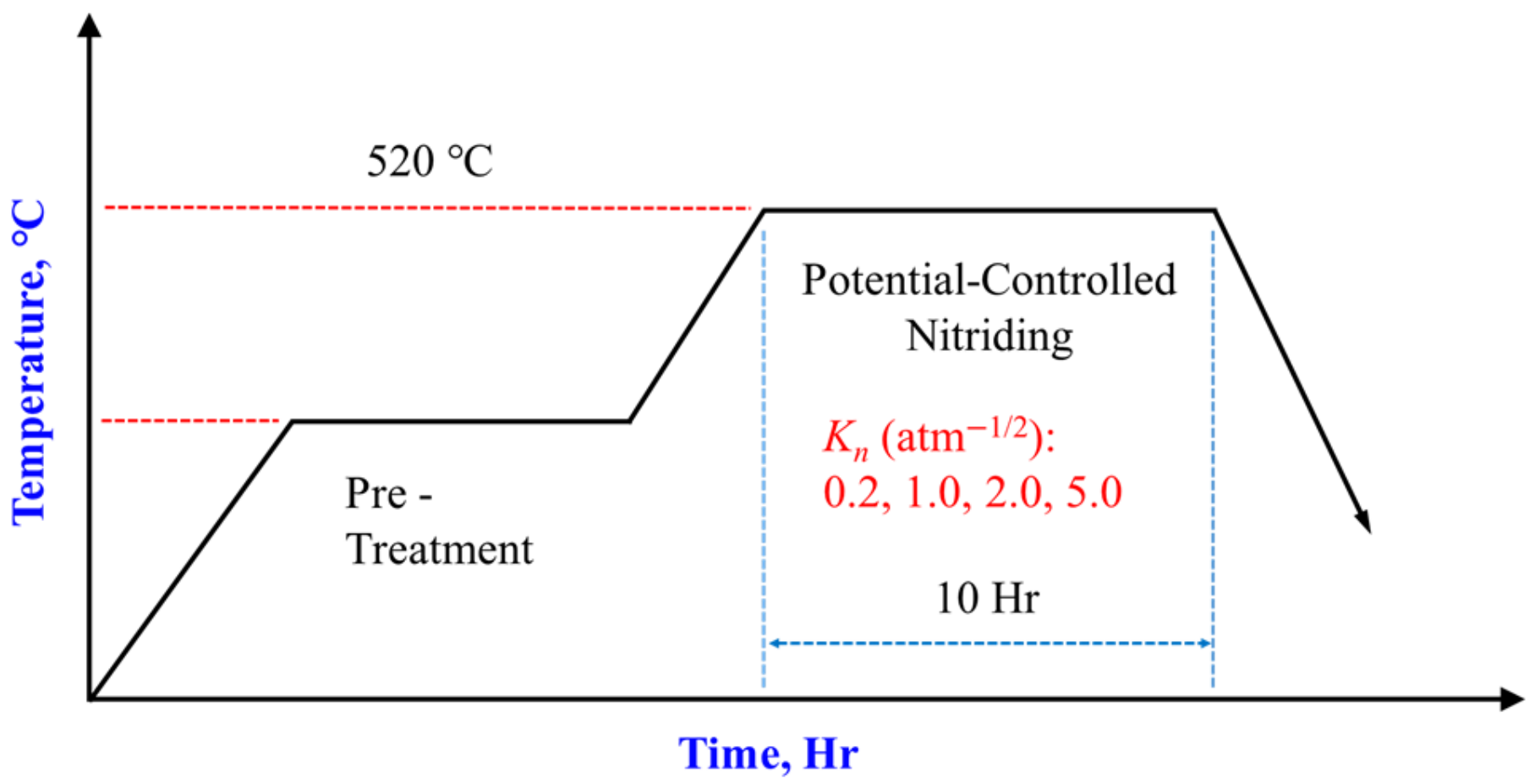
2. Materials and Methods
3. Results
3.1. Hardness
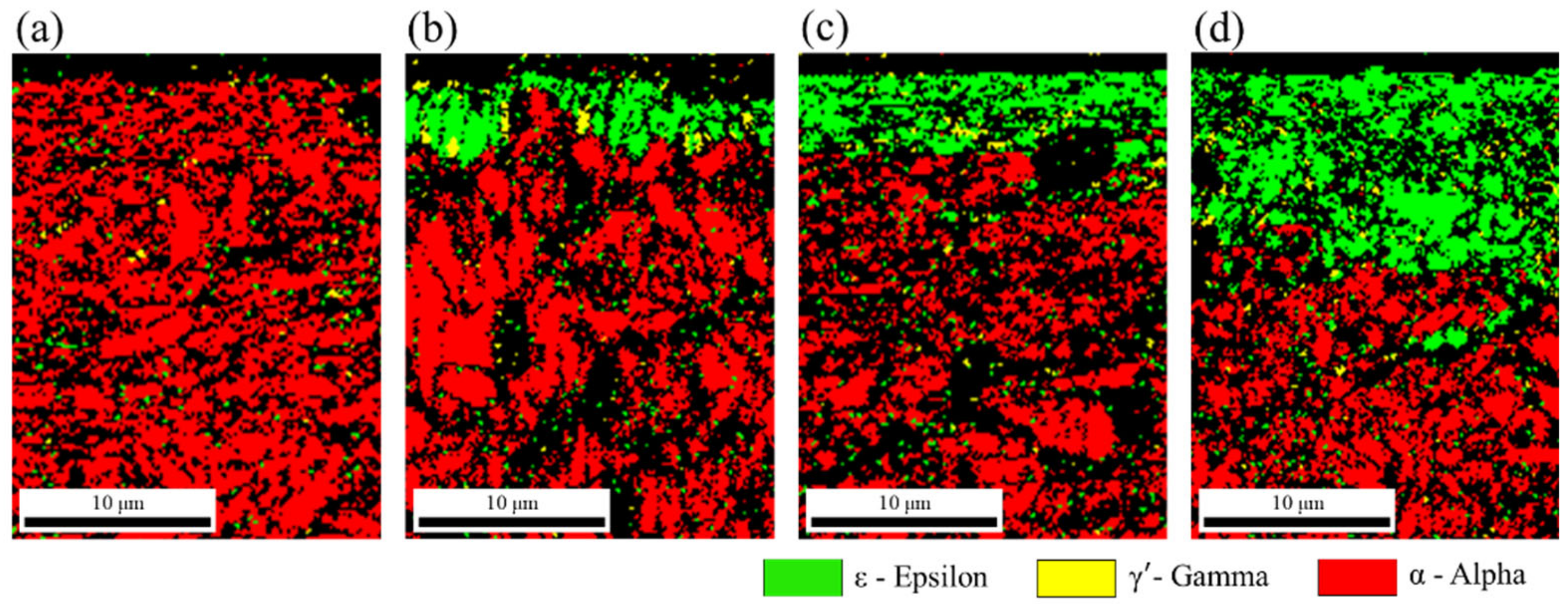
3.2. Microstructure
3.3. Fracture Toughness
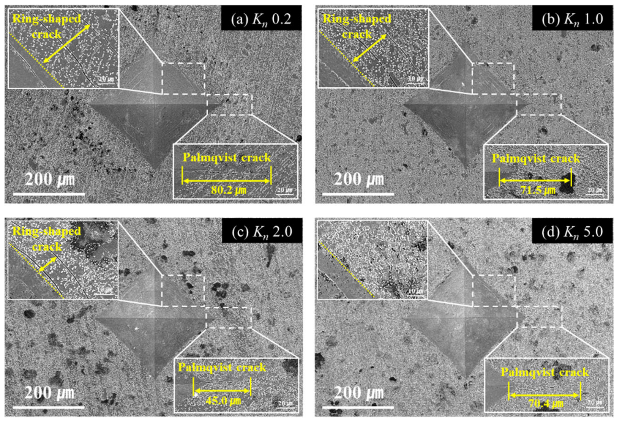
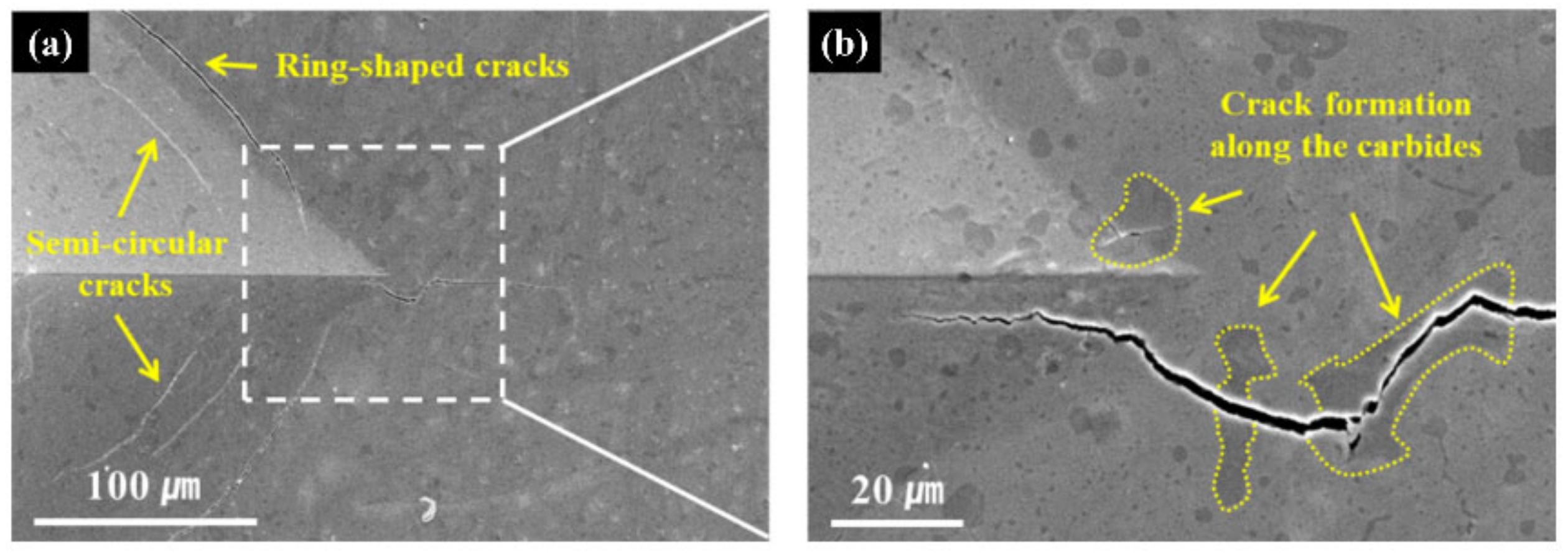
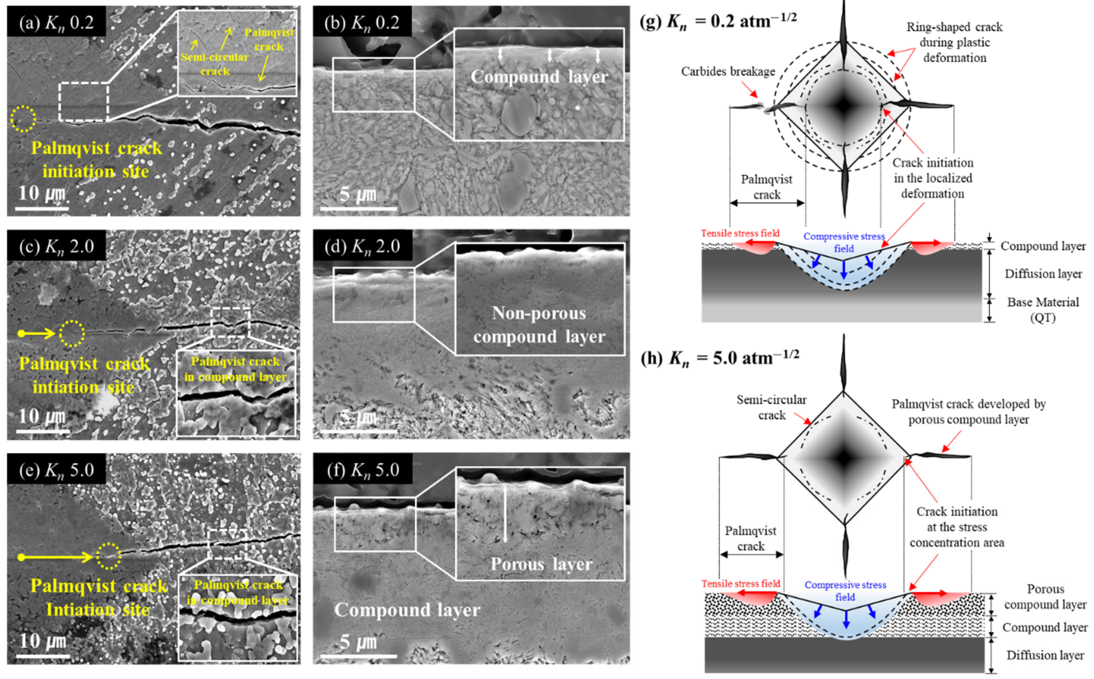
3.4. Crack Characteristics
4. Discussion
5. Conclusions
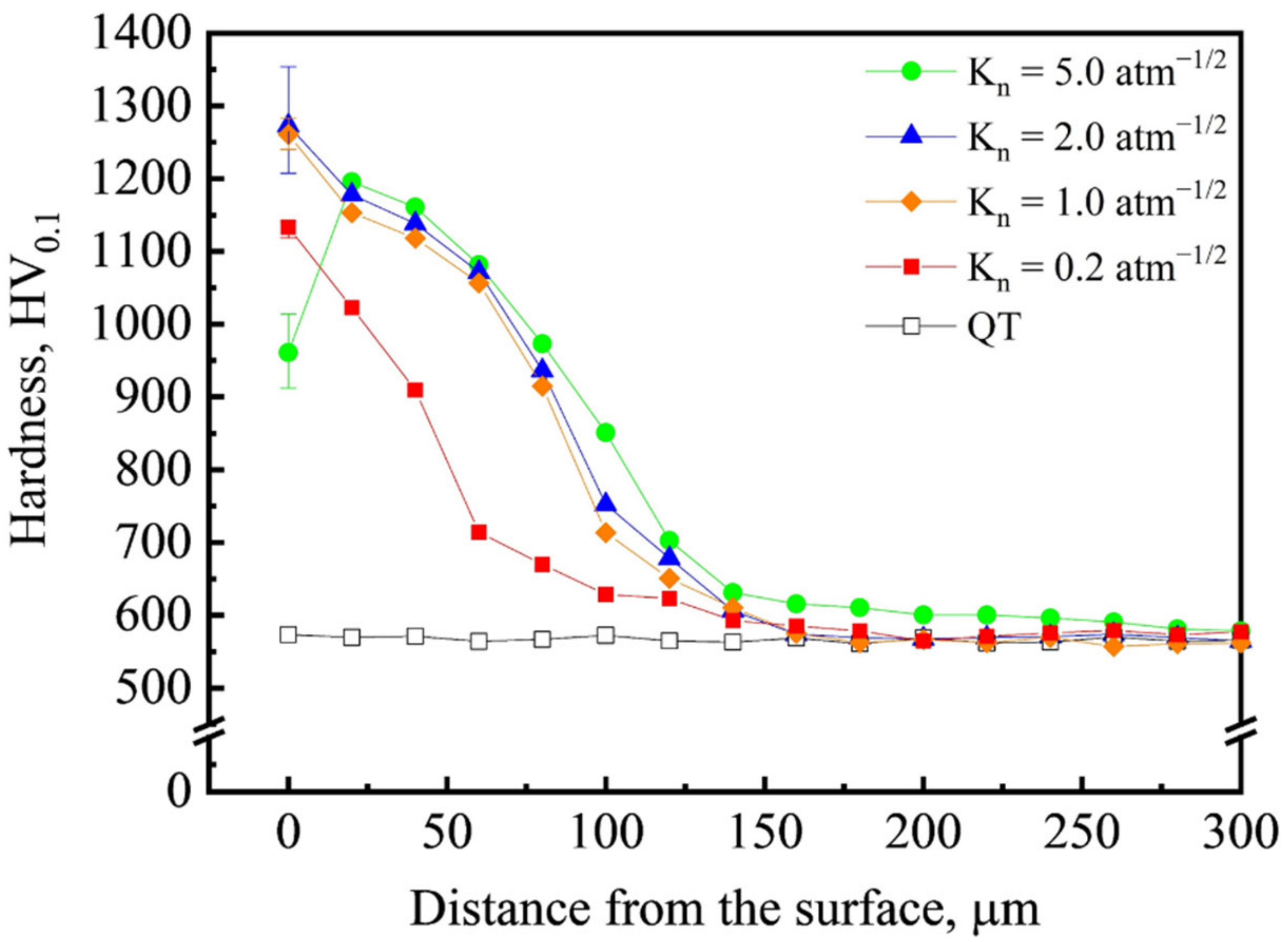
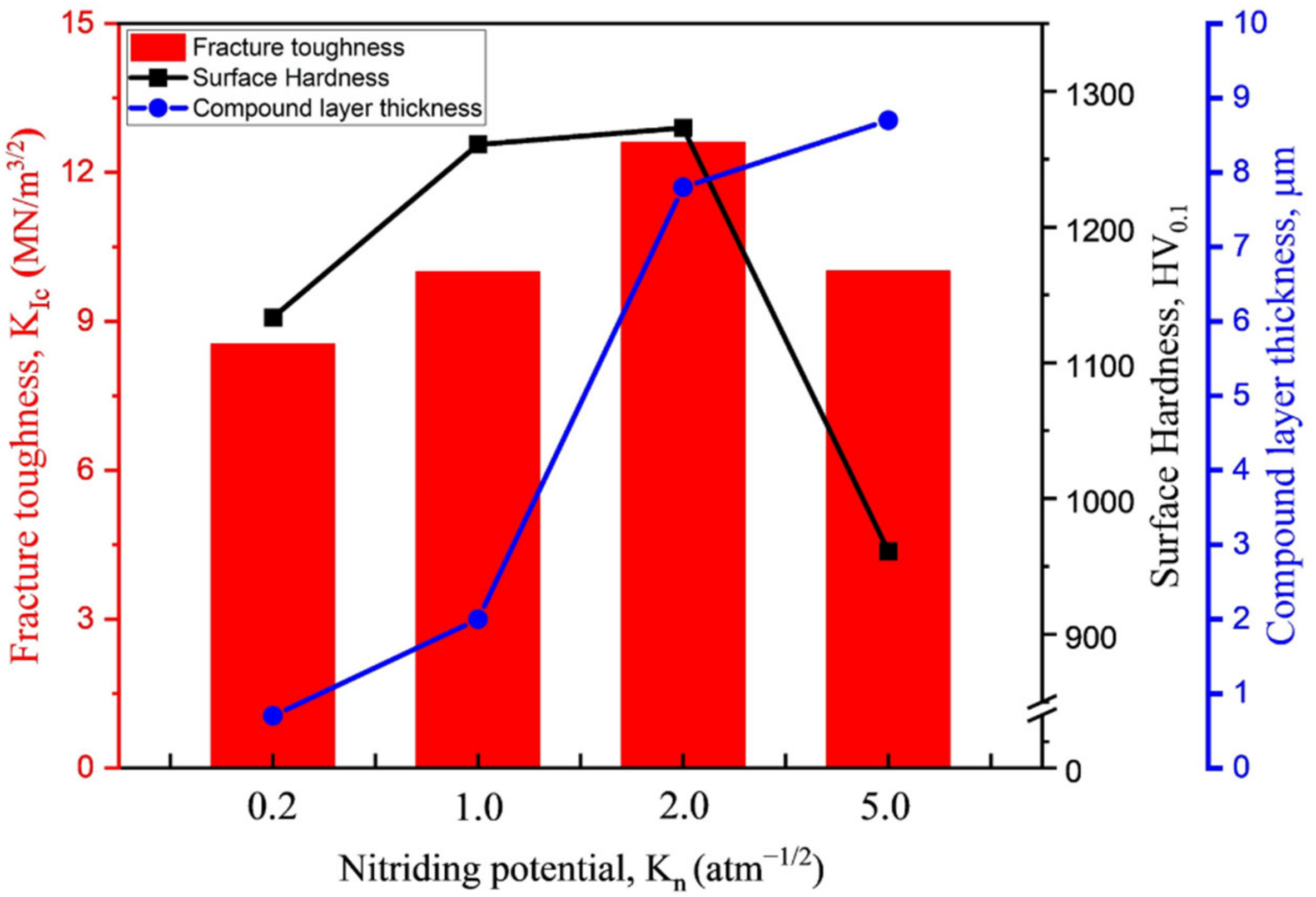
- The average hardness of the heat-treated specimen was measured to be 570 HV0.1, whereas that of the nitrided steel peaked at 1270 HV0.1 for applied nitriding potentials below 5.0 atm−1/2. At the high nitriding potential of Kn = 5.0 atm−1/2, the surface hardness decreased to about 960 HV0.1.
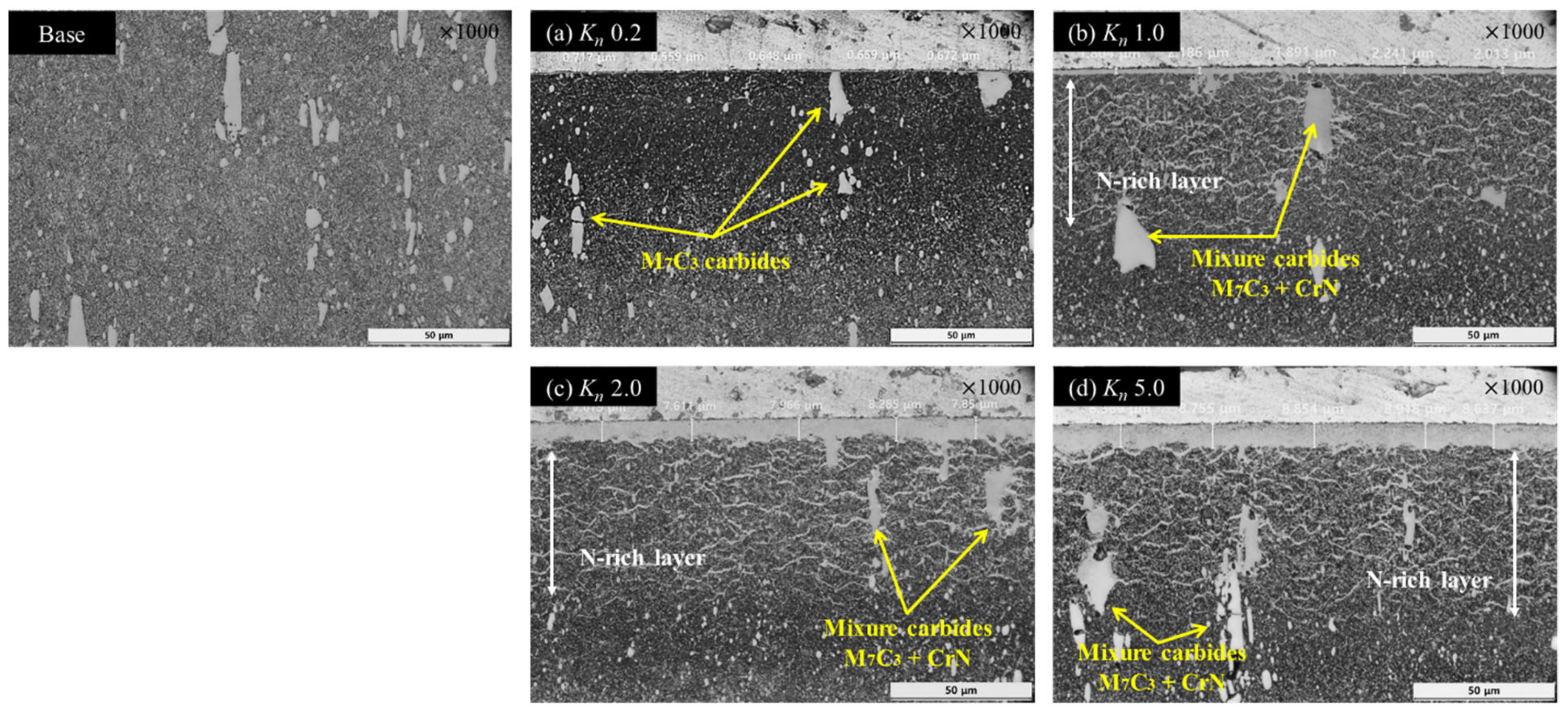
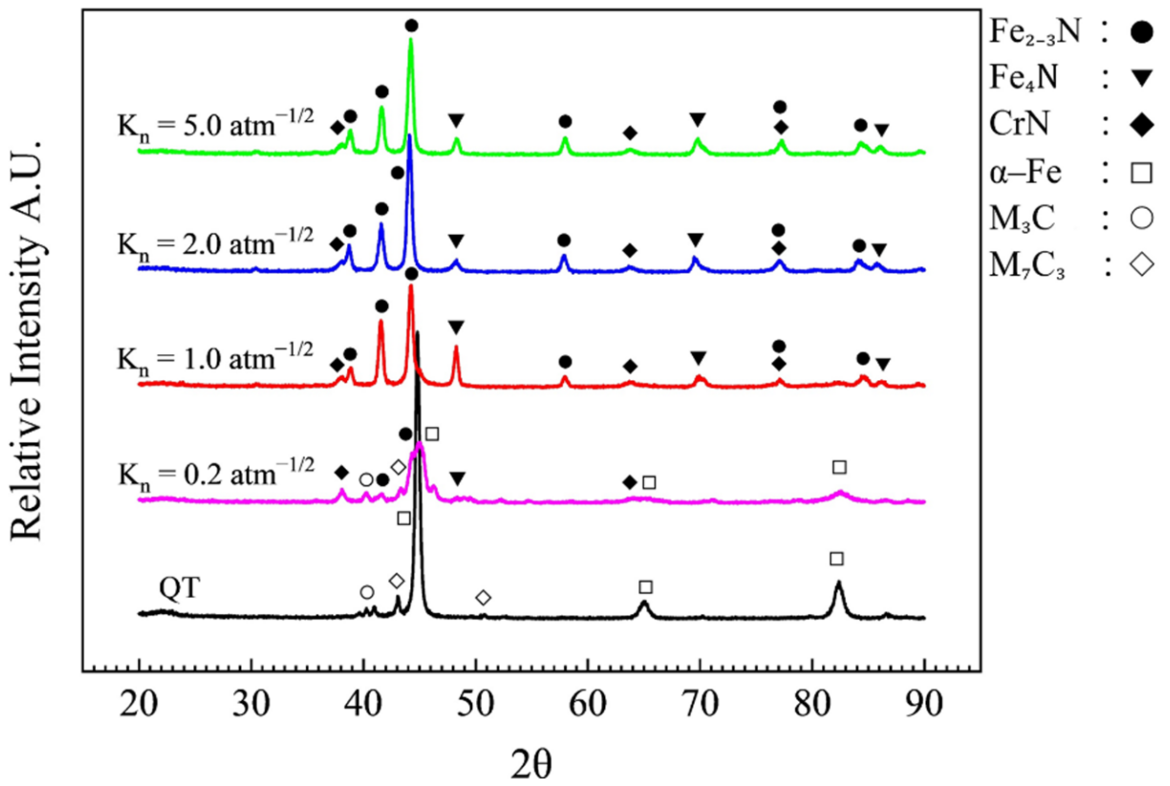
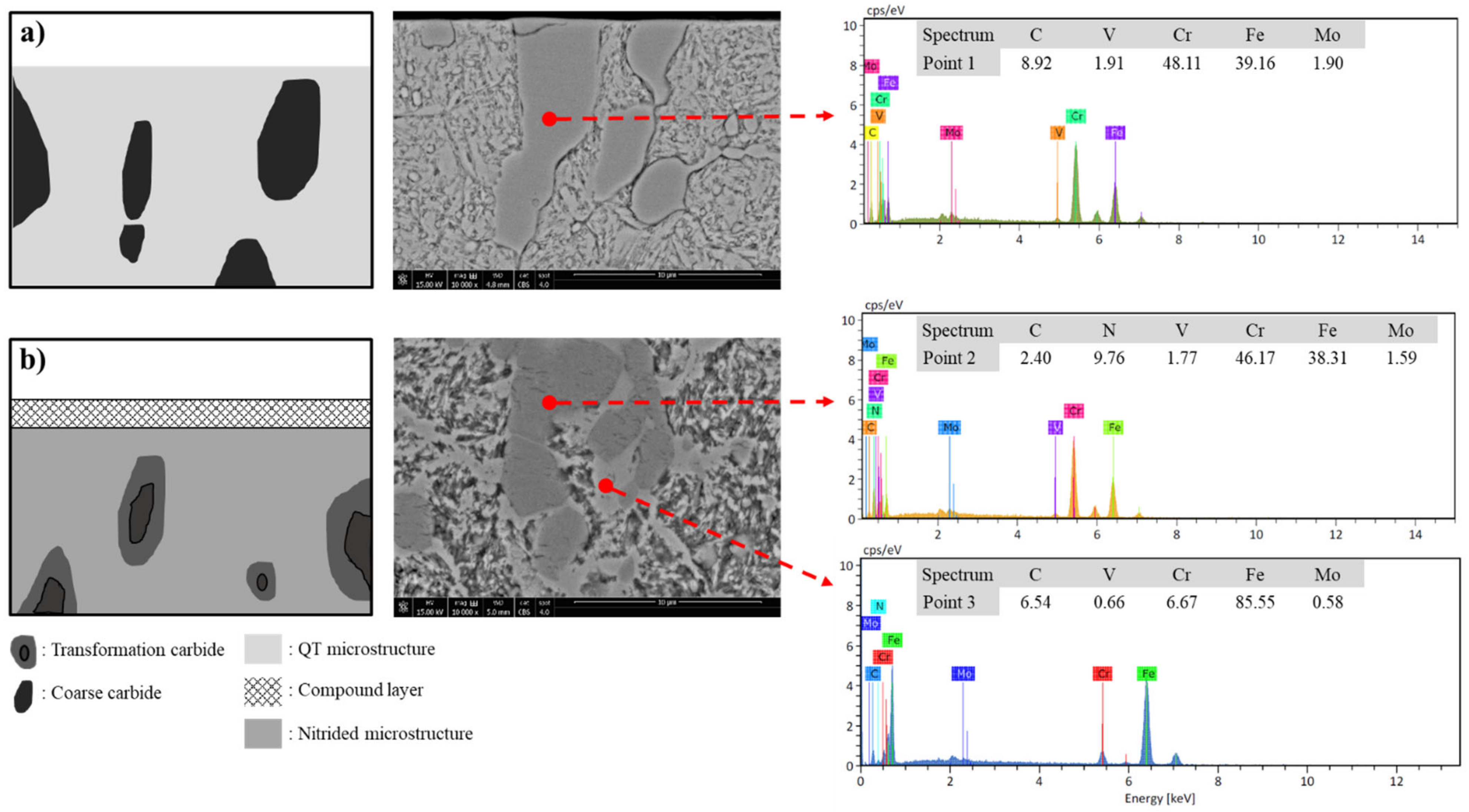
- Chromium nitrides (CrN) develop in the diffusion layer as the carbide precipitation network grows in the carbon-rich zone owing to the recrystallization resulting from nitrogen diffusion. At a nitriding potential of 5.0 atm−1/2, a compound layer consisting of the ε (Fe2–3N) phase grows and develops pores near the surface of the compound layers due to the excess nitrogen.
- The fracture toughness was measured to be approximately 8.5 MN/m3/2 at Kn = 0.2 atm−1/2 at which the compound layer had a thickness of about 0.7 μm. As Kn was increased to 2.0 atm−1/2, the compound layer further increased in thickness, and the fracture toughness peaked at 12.6 MN/m3/2. However, as Kn was further increased to 5.0 atm−1/2, the fracture toughness decreased to approximately 10.0 MN/m3/2 with a decrease in the surface hardness, despite the compound layer growing up to 8.7 μm thick. Thus, the fracture toughness was found to be related to the surface hardness.
- Two main reasons for different crack growth behaviors of the nitrided layers with changes in the nitriding potentials were observed: the location of the initial crack inside the indentation due to the localized deformation of the diffusion layer and an increased crack length due to the porous compound layer. These main factors affected the fracture toughness. In short, with the growth of the non-porous compound layer, the increase in fracture toughness was closely related to the location of the initial crack. This study showed that potential-controlled nitriding can be extended to molds and dies and can improve their mechanical properties, prolonging their service lives.
Author Contributions
Funding
Institutional Review Board Statement
Informed Consent Statement
Data Availability Statement
Acknowledgments
Conflicts of Interest
References
- Roberts, G.; Krause, G.; Kennedy, R. Tool Steels, 5th ed.; ASM International: Materials Park, OH, USA, 1998; pp. 203–217. [Google Scholar]
- Bombac, D.; Fazarinc, M.; Saha Podder, A.; Kugler, G. Study of carbide evolution during thermo-mechanical processing of AISI D2 tool steel. J. Mater. Eng. Perform. 2013, 22, 742–747. [Google Scholar] [CrossRef]
- Fukaura, K.; Yokoyama, Y.; Yokoi, D.; Tsujii, N.; Ono, K. Fatigue of cold-work tool steels: Effect of heat treatment and carbide morphology on fatigue crack formation, life, and fracture surface observations. Metall. Mater. Trans. A 2004, 35, 1289–1300. [Google Scholar] [CrossRef]
- Das, D.; Dutta, A.K.; Ray, K.K. Influence of varied cryotreatment on the wear behavior of AISI D2 steel. Wear 2009, 266, 297–309. [Google Scholar] [CrossRef]
- Torkamani, H.; Raygan, S.; Rassizadehghani, J. Comparing microstructure and mechanical properties of AISI D2 steel after bright hardening and oil quenching. Mater. Des. 2014, 54, 1049–1055. [Google Scholar] [CrossRef]
- Unterweiser, P.M.; Gray, A.G. Source Book on Nitriding; ASM International: Metals Park, OH, USA, 1977; pp. 1–25. [Google Scholar]
- Podgornik, B.; Sedlacek, M.; Cekada, M.; Jacobson, S.; Zajec, B. Impact of fracture toughness on surface properties of PVD coated cold work tool steel. Surf. Coat. Technol. 2015, 277, 144–150. [Google Scholar] [CrossRef]
- Diaz-Guillen, J.C.; Naeem, M.; Hdz-Garcia, H.M.; Acevedo-Davila, J.L.; Diaz-Guillen, M.R.; Khan, M.A.; Iqbal, J.; Mtz-Enriquez, A.I. Duplex plasma treatment of AISI D2 tool steel by combining plasma nitriding (with and without white layer) and post-oxidation. Surf. Coat. Technol. 2020, 385, 125420. [Google Scholar] [CrossRef]
- Kim, Y.-M.; Son, S.W.; Lee, W.-B. Thermodynamic and kinetic analysis of formation of compound layer during gas nitriding of AISI1018 carbon steel. Met. Mater. Int. 2018, 24, 180–186. [Google Scholar] [CrossRef]
- Son, S.-W.; Lee, W.-B. Surface hardening and wear properties of AISI 410 martensitic stainless steel by high & low temperature gaseous nitriding. J. Korean Inst. Surf. Eng. 2018, 51, 249–255. [Google Scholar] [CrossRef]
- Shukla, K.; Purandare, Y.P.; Khan, I.; Ehiasarian, A.P.; Hovsepian, P.E.H. Effect of nitriding voltage on the impact load fatigue and fracture toughness behavior of CoCrMo alloy nitride utilising a HIPIMS discharge. Surf. Coat. Technol. 2020, 400, 126227. [Google Scholar] [CrossRef]
- Somers, M.A.J.; Mittemeijer, E.J. Layer-growth kinetics on gaseous nitriding of pure iron: Evalution of diffusion coeffients for nitrogen in iron nitrides. Metall. Mater. Trans. 1995, 26, 57–74. [Google Scholar] [CrossRef]
- Conci, M.D.; Bozzi, A.C.; Franco, A.R., Jr. Effect of plasma nitriding potential on tribological behaviour of AISI D2 cold-worked tool steel. Wear 2014, 317, 188–193. [Google Scholar] [CrossRef]
- Cho, K.T.; Song, K.; Oh, S.H.; Lee, Y.-K.; Lee, W.B. Enhanced surface hardening of AISI D2 steel by atomic attrition during ion nitriding. Surf. Coat. Technol. 2014, 251, 115–121. [Google Scholar] [CrossRef]
- Lee, W.-B.; Yu, K.-C.; Kim, Y.-M.; Wi, J.-L. Microstructural evolution of compound layers during gaseous nitriding of AISI1045 carbon steels. Korean J. Met. Mater. 2016, 54, 475–482. [Google Scholar] [CrossRef]
- Leite, M.V.; Figueroa, C.A.; Corujeira Gallo, S.; Rovani, A.C.; Basso, R.L.O.; Mei, P.R.; Baumvol, I.J.R.; Sinatora, A. Wear mechanisms and microstructure of pulsed plasma nitrided AISI H13 tool steel. Wear 2010, 269, 466–472. [Google Scholar] [CrossRef]
- Gronostajski, Z.; Widomski, P.; Kaszuba, M.; Zwierzchowski, M.; Polak, S.; Piechowicz, L.; Kowalska, J.; Dlugozima, M. Influence of the phase structure of nitrides and properties of nitrided layers on the durability of tools applied in hot forging processes. J. Manuf. Process. 2020, 52, 247–262. [Google Scholar] [CrossRef]
- Duan, Y.; Qu, S.; Jia, S.; Li, X. Evolution of the fretting wear damage of a complex phase compound layer for a nitrided high-carbon high-chromium steel. Metals 2020, 10, 1391. [Google Scholar] [CrossRef]
- Nolan, D.; Leskovsek, V.; Jenko, M. Estimation of fracture toughness of nitride compound layers on tool steel by application of the Vickers indentation method. Surf. Coat. Technol. 2006, 201, 182–188. [Google Scholar] [CrossRef]
- Arnaud, P.; Heripre, E.; Douit, F.; Aubin, V.; Fouvry, S.; Guiheux, R.; Branger, V.; Michel, G. Micromechanical tensile test investigation to identify elastic and toughness properties of thin nitride compound layers. Surf. Coat. Technol. 2021, 421, 127–303. [Google Scholar] [CrossRef]
- Schwarz, B.; Gohring, H.; Meka, S.R.; Schacherl, R.E.; Mittemeijer, E.J. Pore formation upon nitriding iron and iron-based alloys: The role of alloying elements and grain boundaries. Metall. Mater. Trans. A 2014, 45, 6173–6186. [Google Scholar] [CrossRef] [Green Version]
- Kovacı, H.; Yetim, A.F.; Baran, Ö.; Çelik, A. Fatigue crack growth analysis of plasma nitrided AISI 4140 low-alloy steel: Part1-constant amplitude loading. Mater. Sci. Eng. A 2016, 672, 257–264. [Google Scholar] [CrossRef]
- Roebuck, B.; Bennett, E.; Lay, L.; Morrell, R. Palmqvist Toughness for Hard and Brittle Materials; Measurement Good Practice Guide, No. 9; National Physical Laboratory: Teddington, UK, 2008; pp. 9–11, 19–21. [Google Scholar]
- Pye, D. Practical Nitriding and Ferritic Nitrocarburizing; ASM International: Materials Park, OH, USA, 2003; pp. 1–3, 67–68. [Google Scholar]
- Subhash, G.; Zhang, H. Dynamic indentation response of ZrHf-based bulk metallic glasses. J. Mater. Res. 2007, 22, 478–485. [Google Scholar] [CrossRef]
- Leroy, C.; Michel, H.; Gantois, M. Transformation of (Cr, M)7C3-type carbides during nitriding of chromium alloyed steels. J. Mater. Sci. 1986, 21, 3467–3474. [Google Scholar] [CrossRef]
- Van Wiggen, P.C.; Rozendaal, H.C.F.; Mittemeijer, E.J. The nitriding behaviour of iron-chromium-carbon alloys. J. Mater. Sci. 1985, 20, 4561–4582. [Google Scholar] [CrossRef]
- Zhao, X.; Wang, B.; Sun, D.; Li, C.; Han, L.; Gu, J. Effect of pre-existing VC carbides on nitriding and wear behavior of hot-work die steel. Appl. Surf. Sci. 2019, 486, 179–186. [Google Scholar] [CrossRef]
- Mittermeijer, E.J.; Somers, M.A.J. Thermochemical Surface Engineering of Steels; Woodhead Publishing: Sawston, UK, 2015; pp. 342–343. [Google Scholar]
- Zhang, G.; Cui, H.; Zhang, H.; Cheng, G. Micro-porous layer generated during gas nitriding and induction quenching compound treatment affects tribological properties. Tribol. Int. 2018, 120, 226–232. [Google Scholar] [CrossRef]


| C | Si | Mn | P | S | Cr | Mo | V | Fe |
|---|---|---|---|---|---|---|---|---|
| 1.52 | 0.4 | 0.53 | 0.04 | 0.02 | 12.8 | 0.99 | 0.38 | Bal. |
Publisher’s Note: MDPI stays neutral with regard to jurisdictional claims in published maps and institutional affiliations. |
© 2022 by the authors. Licensee MDPI, Basel, Switzerland. This article is an open access article distributed under the terms and conditions of the Creative Commons Attribution (CC BY) license (https://creativecommons.org/licenses/by/4.0/).
Share and Cite
Kim, K.-H.; Lee, W.-B.; Kim, T.-H.; Son, S.-W. Microstructure and Fracture Toughness of Nitrided D2 Steels Using Potential-Controlled Nitriding. Metals 2022, 12, 139. https://doi.org/10.3390/met12010139
Kim K-H, Lee W-B, Kim T-H, Son S-W. Microstructure and Fracture Toughness of Nitrided D2 Steels Using Potential-Controlled Nitriding. Metals. 2022; 12(1):139. https://doi.org/10.3390/met12010139
Chicago/Turabian StyleKim, Ki-Hong, Won-Beom Lee, Tae-Hwan Kim, and Seok-Won Son. 2022. "Microstructure and Fracture Toughness of Nitrided D2 Steels Using Potential-Controlled Nitriding" Metals 12, no. 1: 139. https://doi.org/10.3390/met12010139