Article

The Role of Graphitic Carbon Nitride in the Formulation of Copper-Free Friction Composites Designed for Automotive Brake Pads

1
Department of Chemistry, Faculty of Materials Science and Technology, VSB-Technical University of Ostrava, 17. Listopadu 2172/15, 708 33 Ostrava, Czech Republic
2
Institute of Environmental Technology, CEET, VSB-Technical University of Ostrava, 17. Listopadu 2172/15, 708 33 Ostrava, Czech Republic
3
Advanced R&D Department, Brembo S.p.A., 24040 Stezzano, Italy
4
Department of Industrial Engineering, University of Trento, Via Sommarive 9, Povo, 38123 Trento, Italy
*
Author to whom correspondence should be addressed.
Metals 2022, 12(1), 123; https://doi.org/10.3390/met12010123
Submission received: 25 November 2021 / Revised: 19 December 2021 / Accepted: 6 January 2022 / Published: 9 January 2022
(This article belongs to the Special Issue New Developments in Friction Brake Materials)

Abstract

:
In this study, graphitic carbon nitride (g-C3N4, labelled as gCN) was tested in the formulation of copper-free (Cu-free) friction mixtures, which are potentially interesting for brake pad manufacturing. Three formulations of friction composites were prepared starting from a common Cu-free master batch: (i) without graphite, (ii) with graphite and (iii) with gCN. The mixtures were pressed in the form of pins by hot-press moulding. The friction-wear performance of the prepared pins was investigated using a pin-on-disc (PoD) test at room temperature (RT), high temperature (HT) (400 °C) and, again, at room temperature (H-RT). The values of the friction coefficient (µ) for the composites with gCN (or graphite) were as follows: (i) RT test, µRT = 0.52 (0.47); (ii) HT test, µHT = 0.37 (0.37); (iii) RT after the HT tests, µH-RT = 0.49 (0.39). With respect to wear resistance, the samples with graphite performed better than the samples without this solid lubricant. To the best of our knowledge, this is the first report regarding the evaluation of the role of gCN in friction composites designed for automotive brake lining applications. The results indicate the main role of gCN as a soft abrasive.

Graphical Abstract

1. Introduction

Friction materials designed for automotive brake linings are usually classified into three main groups: semi-metallic, non-asbestos organic (NAO) and ceramic [1]. In addition, copper metal matrix composites should also be taken into account, even if there is an effort to completely remove the copper from the brake pad formulation [2]. The friction-wear properties of brake linings are tested on the “material level” using pin-on-disc testers [3], subscale dyno-bench testers [4] or at the “system level” using a full-scale dynamometer [5].
Friction mixtures used to manufacture automotive brake pads consist of several components belonging to four main groups: (i) abrasives, (ii) fillers, (iii) solid lubricants and (iv) binders. Usually, the multiple functionalities of each component are observed. Thousands of raw materials have already been tested as components of friction mixtures [6]. Alumina, silicon carbide, and zircon are well-known abrasives [7,8,9], and their role is to maintain a certain friction coefficient (µ) and prevent its decrease with increasing temperature (a phenomenon called fading). The role of the abrasives is to renew the friction layer formed on the surfaces of both pads and discs. Although the main role of abrasives in friction composites is to affect the friction coefficient, there are also studies related to their effect on wear particle production as reported by Park et al. [10]. Graphite and layered sulphides are the most commonly used solid lubricants [11,12,13,14], and their role is to stabilise the friction coefficient during braking (smoothing of the brake action) and reduce the wear rate. The fillers can be further subdivided into particulate fillers or fibres, both synthetic and natural. The fillers are intended to create the primary contact plateaus, strengthen the entire friction composite, and fill up its volume [15,16,17,18,19]. Phenolic resin is the most frequently used binder, and it is utilised to hold all the components together. Although other types of binders have been tested, phenolic resin remains to date the most frequently used [20]. The proper combination of the components from all the groups and the selection of the hot-pressing process are the key factors that ensure the required functionality of the final brake lining [21,22,23].
The growing nanotechnology sector has introduced a number of components with unique properties, mainly owing to the nanometre-length scale of these materials. Several of these materials have already been tested as components of friction materials. The effect of graphene on the friction-wear performance of semi-metallic friction composites containing brass for use in car brake linings was studied by Rajan et al. [24]. In comparison to traditional graphite, the authors observed several positive effects of graphene on the friction stability, fade performance and wear rate reduction. The effect of nanosized abrasives of Al2O3, SiC, and SiO2 on the friction-wear performance of Cu-containing friction composites was investigated by Bijwe et al. [25]. The authors reported the positive effect of the nanosized abrasives in terms of reduced wear rate and tuning of the friction performance. Mahale et al. [26] investigated the effect of potassium titanate nano- and micro-particles on the friction wear performance of NAO friction composites containing brass. Improved wear resistance and friction performance were obtained for composites with nanosized potassium titanate. Efforts are continuously made to replace Cu in the formulations [27,28,29]. For example, Bhatt et al. [30] studied the effect of hydrated calcium silicate on NVH performance in Cu-free formulations and indicated the positive effect of this component on most of the tribological properties of prepared samples.
Recently, gCN has attracted research interest for photocatalytic applications [31], for the preparation of anodes for batteries [32], and as sensors [33]. gCN, usually in the form of a yellow powder, shows a layered structure, and the layers are made of a net of heptazine rings bonded together by van der Waals forces [34]. There are several reported methods for the preparation of gCN, mainly based on the thermal polycondensation of a suitable precursor, with melamine [35] being the most widely used precursor. The stacked layers of bulk gCN can be separated, and nanoflakes of gCN can be obtained [36]. Bulk gCN is similar to graphite, while isolated nanoflakes, in some respects, are similar to graphene. The effect of gCN in polymer composites based on polyimide was tested by Zhu et al. [37]. The authors observed that the use of bulk gCN decreased the friction coefficient and wear rate of the prepared polymer matrix composites. Duan et al. [38] tested nanostructured gCN as the filler in a polyimide matrix and, similar to Zhu et al. [37], the authors observed improved wear resistance of the resulting composites, which increased with increasing testing temperature. However, the friction coefficient also slightly increased with increasing testing temperature. Zhang et al. [39] studied the effect of micro-sized and exfoliated gCN on the wear resistance of polymer matrix composites based on a poly–ether–ether–ketone matrix under oil lubrication conditions. The author observed that even a low addition of nanostructured gCN to the polymer matrix significantly improved the wear resistance of the composite. The characteristics of gCN, as well as previously published results, suggest that gCN should behave as a solid lubricant in friction materials dedicated to automotive brake pads.
In this paper, a preliminary assessment of the functionality of gCN in the formulation of Cu-free friction composites is reported. Composites with 9 wt.% of synthetic graphite and 9 wt.% of gCN were prepared in the form of pins by hot-press moulding. A composite without graphite or gCN was used as a reference. The dry sliding behaviour of the samples was assessed using a pin-on-disc test rig.

2. Materials and Methods

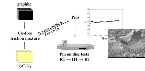
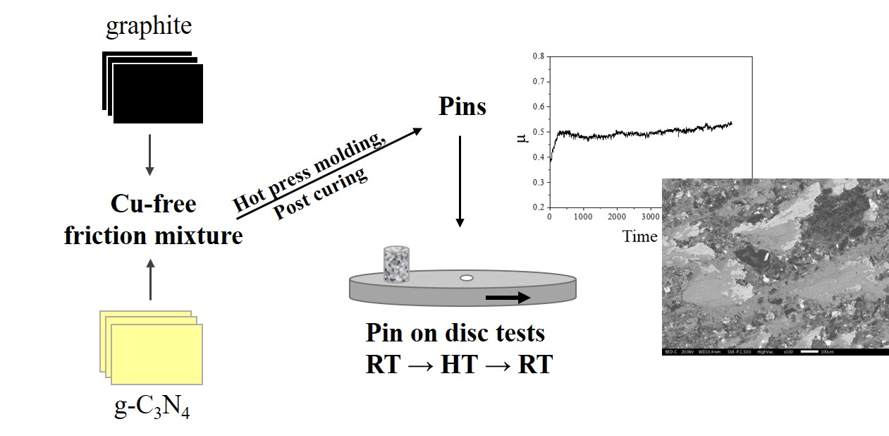
2.1. Master Batch and Graphite

A Cu-free master batch of the friction mixture (Brembo S.p.A., Stezzano, Italy), labelled M0, was used as a reference. The friction mixture M0 did not contain any graphite to better understand the role of gCN in friction composites. The main components of M0, their roles, and their estimated amounts are given in Table 1.
The characteristics of the masterbatch studied using scanning electron microscopy (SEM) are shown in Figure 1a. Some of the main constituents were identified using energy-dispersive X-ray (EDX) local microanalysis, and the results showed the presence of steel fibres, vermiculite, aluminium oxide, magnesium oxide, and tin sulphide.
Commercial synthetic graphite (labelled as G) obtained from Imerys Graphite and Carbon (Bironico, Switzerland) was selected as the standard solid lubricant for addition to masterbatch M0. The microstructure of the fine black G powder is shown in Figure 1b. The particle size distributions of the G particles, taken from the technical data sheet, are listed in Table 2.

2.2. Graphitic Carbon Nitride

Sample gCN was prepared by thermal polycondensation of melamine in two steps. In the first step, melamine (Sigma–Aldrich, St. Louis, MO, USA) was heated for 10 min in a semi-closed crucible at 475 °C (heating rate 5 °C/min) in a muffle furnace LAC LMH (LAC, Brno, Czech Republic). The samples were then removed from the furnace and allowed to cool under laboratory conditions. In the second step, the crucible was placed in the same muffle furnace, preheated to 550 °C, and held for 2 h at this temperature. A very fine yellow powder was obtained directly and assigned as gCN. The prepared sample of gCN was characterised via X-ray diffraction (XRD) using a MiniFlex600 diffractometer equipped with a Co tube and a D/teX Ultra detector (Rigaku, Tokio, Japan). The diffraction pattern was recorded in the 2θ range of 10–80° with a step size of 0.01° and a speed of 2°/min. The infrared spectra of the gCN sample were recorded using the attenuated total reflection (ATR) mode of a Thermo Scientific Nicolet 6700 Fourier transform infrared (FTIR) spectrometer (Thermo Fisher Scientific, Waltham, MA, USA). The spectra were recorded in the range of 400–4000 cm−1 with a resolution of 2 cm−1, and the obtained spectrum was the average of 64 scans.

2.3. Modification of the Master Batch with gCN and G

To reveal the effect of gCN on the friction-wear performance of the Cu-free friction composites, two new formulations were prepared from the reference masterbatch M0 by the addition of:
  • 9 wt.% of G: formulation labelled as M0_G;
  • 9 wt.% of gCN: formulation labelled as M0_CN.
The content of 9 wt.% of graphite was selected intentionally based on our previous experience with this component [40]. The formulations were mixed for 20 min using the shaker mixer TURBULA® T 2 F (Willy A. Bachofen AG, Muttenz, Switzerland). The powder mix was pressed for 10 min in a cylindrical mould using a BUEHLER hot-mounting press (Buehler, Lake Bluff, IL, USA) at a constant pressure of 17 MPa and a temperature of 150 °C to obtain the specimens for the tribological tests. Cylindrical samples with a diameter of 10 mm and a height of 10 mm were successively post-cured in a laboratory oven UN55 (Memmert GmbH + Co. KG, Schwabach, Germany) for 4 h at 200 °C in air. The bulk densities of the pins, 2.25 ± 0.05 g·cm−3, were determined based on their weight (m) and volume (V).

2.4. Characterisation of the Thermal Stability of gCN, G, and the Prepared Friction Composites

Thermogravimetric (TG) analysis was performed to study the thermal stability of graphitic carbon nitride, graphite, and the friction composites M0, M0_G and M0_CN. TG measurements were performed on an SDT650 simultaneous thermal analyser (TA Instruments, New Castle, DE, USA) in a dynamic air atmosphere (10 L·min−1). The samples (10 mg) were placed in an alumina crucible and heated in the temperature range of 25–900 °C at a heating rate of 10 °C·min−1.

2.5. Pin-On-Disc Tests

Tribological tests were performed under dry sliding conditions using a Ducom pin-on-disc (PoD) apparatus (Ducom Instruments Pvt. Ltd., Bengaluru, India). A pearlitic grey cast iron disc 60 mm in diameter with a Vickers hardness of 235 HV10 measured on QNESS 60 A+ EVO (ATM Qness GmbH, Golling, Austria) was used as the counterface. A sliding velocity of 1.50 m·s−1 and a nominal contact pressure of 1 MPa were kept constant during the tests. The selected sliding velocity and contact pressure corresponded to mild braking conditions; if scaled to a small passenger car, the testing velocity approximately corresponded to a vehicle speed of 13 km·h−1. The duration of each test was 90 min.
First, tests were performed at room temperature (RT). A preliminary 30 min long bedding procedure was conducted to allow conformal contact between the pin and the disc surfaces and to remove the coarser surface asperities. To assess the friction-wear performance of the samples at elevated temperatures, testing of the composites at high temperature (HT) was also carried out following the procedure established by Leonardi et al. [40]. The high-temperature tests were carried out using an induction heating apparatus enclosing the pin-on-disc testing chamber to heat the disc at 400 °C. To reveal the recovery performance, further tests were conducted at room temperature (H_RT) on the same specimens obtained after the HT tests were conducted. This sequence of testing conditions (RT and HT followed by H_RT) was adopted to investigate the recovery capability of all of the prepared friction materials under investigation (i.e., M0, M0_G and M0_CN). Two pins were tested for each material, and the average friction coefficient was calculated.
The coefficient of friction was continuously recorded during each test. The wear of the pins was evaluated by weighing the sample before and after each test using an analytical balance Kern ADJ (KERN & SOHN GmbH, Balingen, Germany) with a precision of 10−4 g. From these data, the specific wear coefficient (Ka), calculated using Equation (1), was evaluated.
Ka = V/(Fn·s)
where V (m3) is the measured wear volume, Fn (N) is the applied load, and s (m) is the sliding distance.
A scanning electron microscope (SEM) JEOL IT300 (JEOL Ltd., Tokyo, Japan) operated at an accelerated voltage of 20 kV was used to study the morphology of G and gCN particles, as well as to characterise the friction surfaces after the PoD test. SEM images of G and CN were obtained using a secondary electron detector, and the images of the friction surfaces were obtained in the backscattered electron mode. For local chemical analysis of the worn surfaces at the end of the PoD test, an energy-dispersive X-ray spectroscopy (EDXS) system was used.

3. Results and Discussion

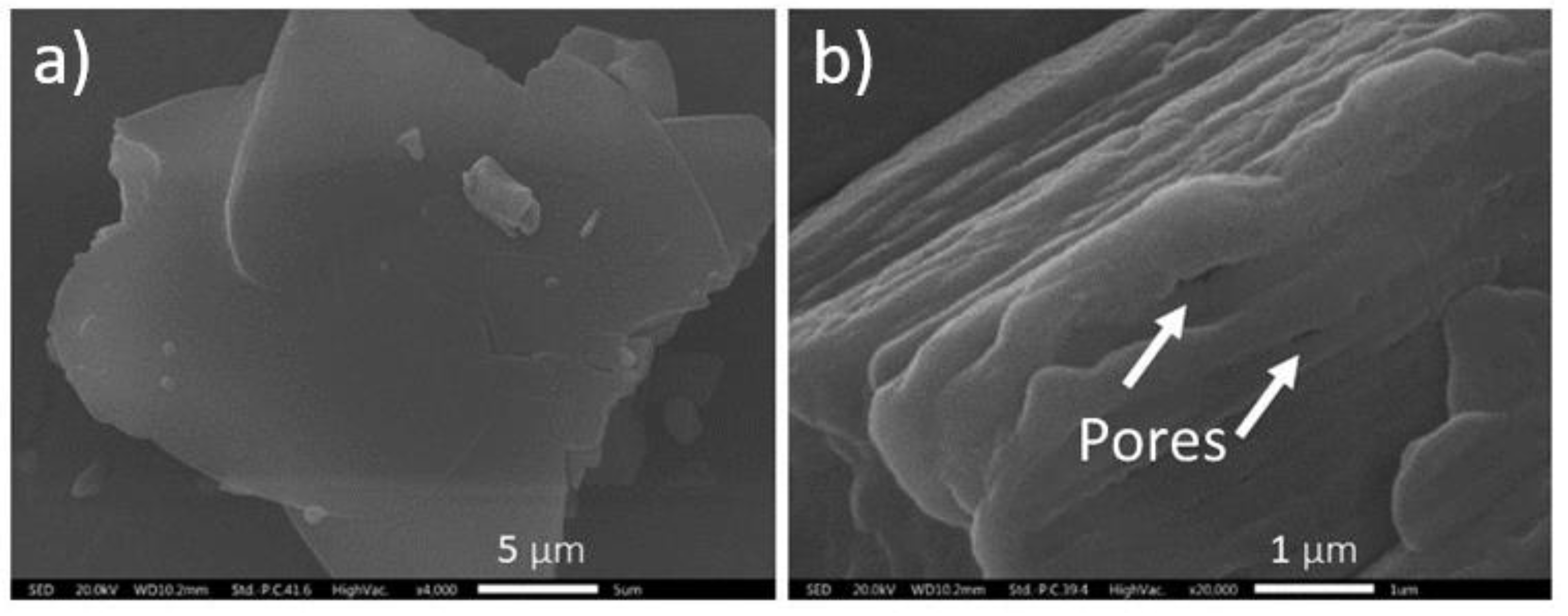
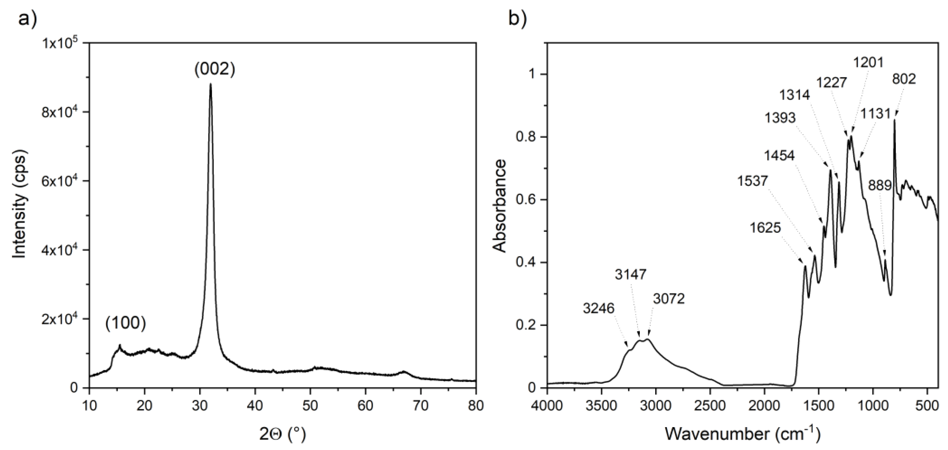
3.1. Characterisation of gCN

SEM micrographs of the synthesised gCN powder are shown in Figure 2.
The structure of gCN is a graphite-like layered material (covalent bonds of carbon and nitrogen replace the carbon and carbon bonds in graphite). A large planar network structure is clearly visible in the SEM image in Figure 2a. The detail of another observed particle documenting the presence of pores originating during gCN synthesis is shown in Figure 2b. EDXS analyses were performed to qualitatively check the composition of the gCN particles (Table 3).
As expected, the gCN consisted of carbon and nitrogen. The detected aluminium came from the material used to support the powders during SEM observations, and a small amount of oxygen was found as a typical contaminant of gCN [41].
The X-ray diffraction pattern and FTIR spectra of the gCN sample are shown in Figure 3a,b, respectively.
The XRD pattern of gCN (Figure 3a) shows two peak intensities at (100) and (002), demonstrating the presence of g-C3N4 [42]. The diffraction peak (100) was related to the in-plane ordering of nitrogen-linked heptazine units, whereas diffraction peak (002) describes the interlayer stacking of the melem planes.
The FTIR spectra of gCN (Figure 3b) exhibited bands with maxima at frequencies typical of g-C3N4. The bands in the region from 1700 to 1100 cm−1 were related to the stretching vibrations of aromatic C–N heterocycles [43]. The sharp characteristic peak with a maximum at 802 cm−1 describes the breathing vibration of the tri-s-triazine ring system [44]. The bands observed in the region of 3500–2500 cm−1 were attributed to the stretching modes of N–H and O–H bonds of free surface amino groups and adsorbed hydroxyl species [45].

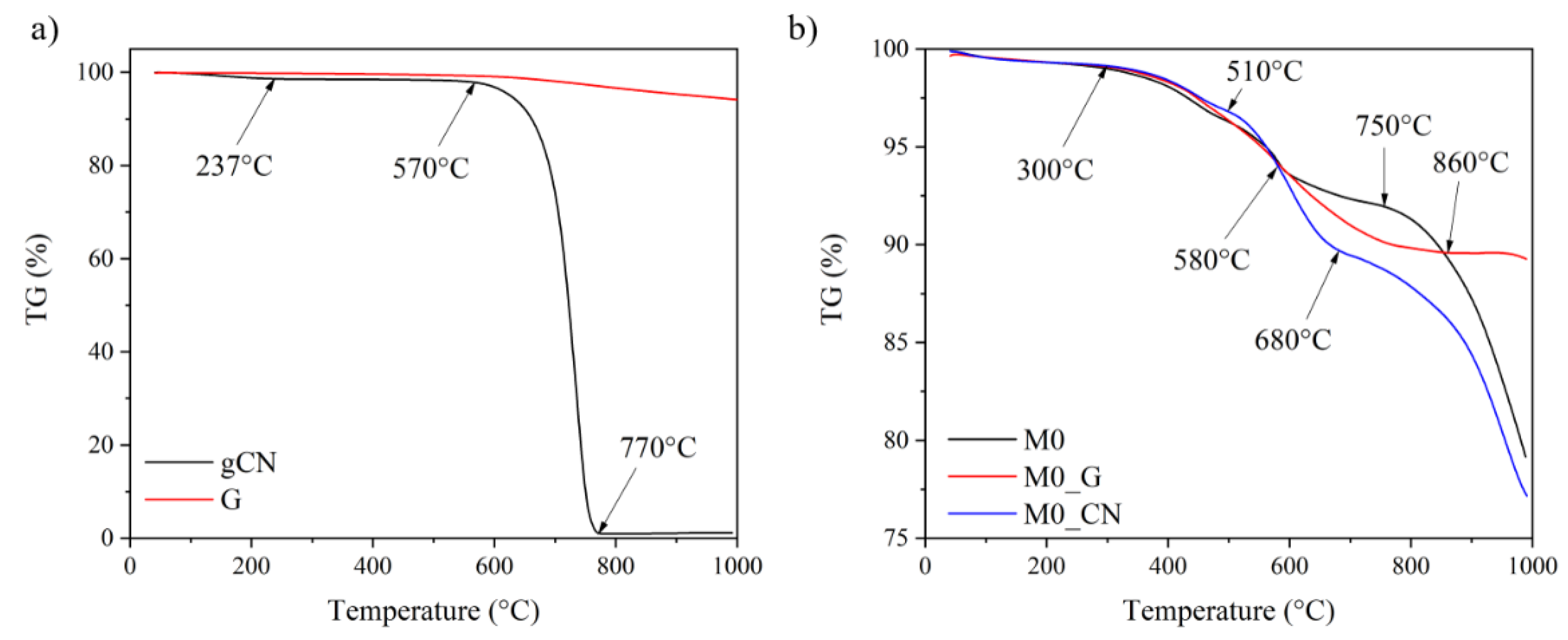
3.2. Thermal Stability of the Friction Composites

The TG curves for gCN prepared in this study and commercially available G are shown in Figure 4a. The figure clearly indicates the high thermal stability of G; it also shows the thermal stability of gCN up to 570 °C.
The thermal stability of the friction composites is documented by the TG curves shown in Figure 4b. The thermal behaviour of all of the composites was similar up to 580 °C; above this temperature, the TG curves of all three friction composites differed. The weight loss of the M0_CN composite above 580 °C was the most pronounced. The overall weight loss of the M0_CN composite in the temperature range of 510–680 °C was 8%. Because all of the tested friction composites were of complex composition, it is difficult to address the individual contribution of each component to the thermal degradation of the friction composites at a given temperature. However, Figure 4a clearly shows the thermal stability of gCN up to 570 °C; thus, the weight loss of the M0_CN composite in the temperature range of 510–680 °C reflects the decomposition of gCN (TG curve for sample M0_CN in Figure 4b). The addition of graphite to the reference mixture M0 (composite M0_G) improved the thermal stability of the M0_G composite as shown in Figure 4b. In terms of the thermal stability, the friction composite with graphite showed preferable behaviour.

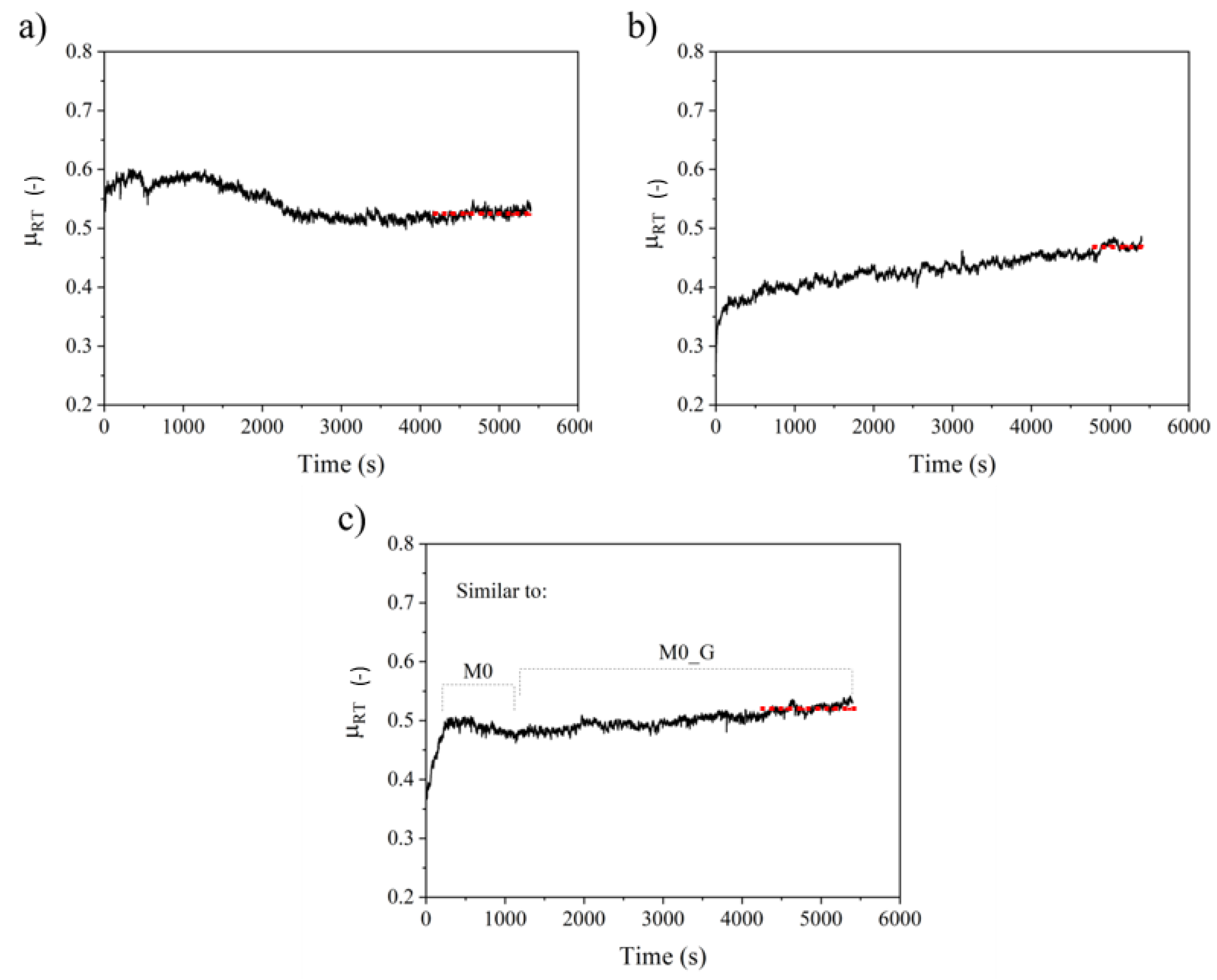
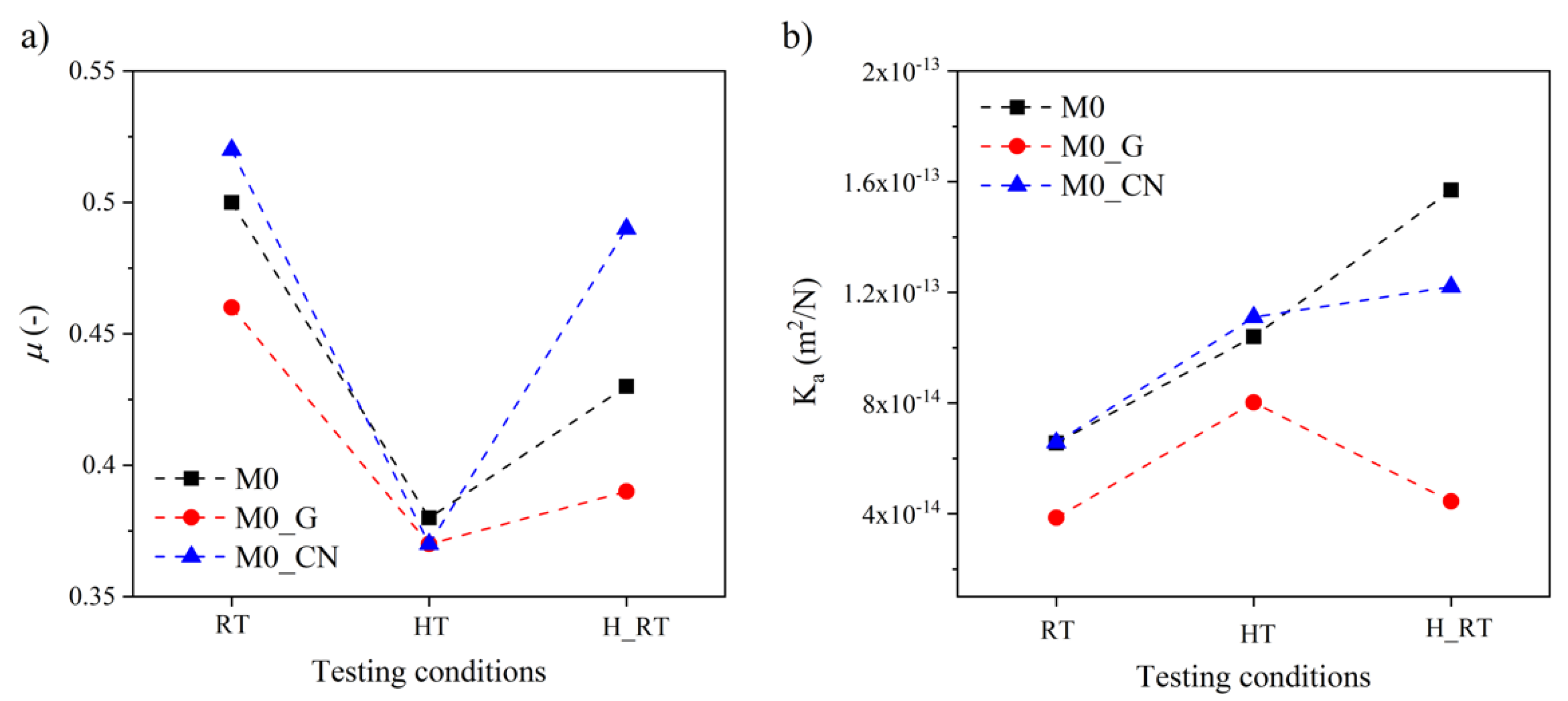
3.3. Friction and Wear Behaviour at RT

The time evolution of the friction coefficient (µRT) of the M0, M0_G and M0_CN samples tested under RT conditions is shown in Figure 5.
In Figure 5a, sample M0 displays running-in (stabilisation of the friction performance) with high and unstable µRT values that decrease with time to a steady-state condition. Sample M0_G (Figure 5b) shows a continuous increase in µRT that stabilises only in the latter part of the test. Sample M0_CN (Figure 5c) displays intermediate behaviour. Initial running-in was observed in the initial part of the test, characterised by an increase in µRT followed by a decrease, similar to M0, followed by a continuous increase in µRT, similar to M0_G. The average values of the friction coefficient in the final steady-state part of the tests (the selected steady state is marked by the red, dotted lines in Figure 5) are listed in Table 4.
The sample containing graphite, M0_G, exhibited the lowest friction coefficient. The material with gCN, M0_CN, showed the highest value of µRT in comparison to both the M0 and M0_G samples. The mean values of Ka calculated for all three friction composites are also listed in Table 4. There was no significant difference in the mean Ka values for M0 and M0_CN. M0_G exhibited the lowest wear rate.

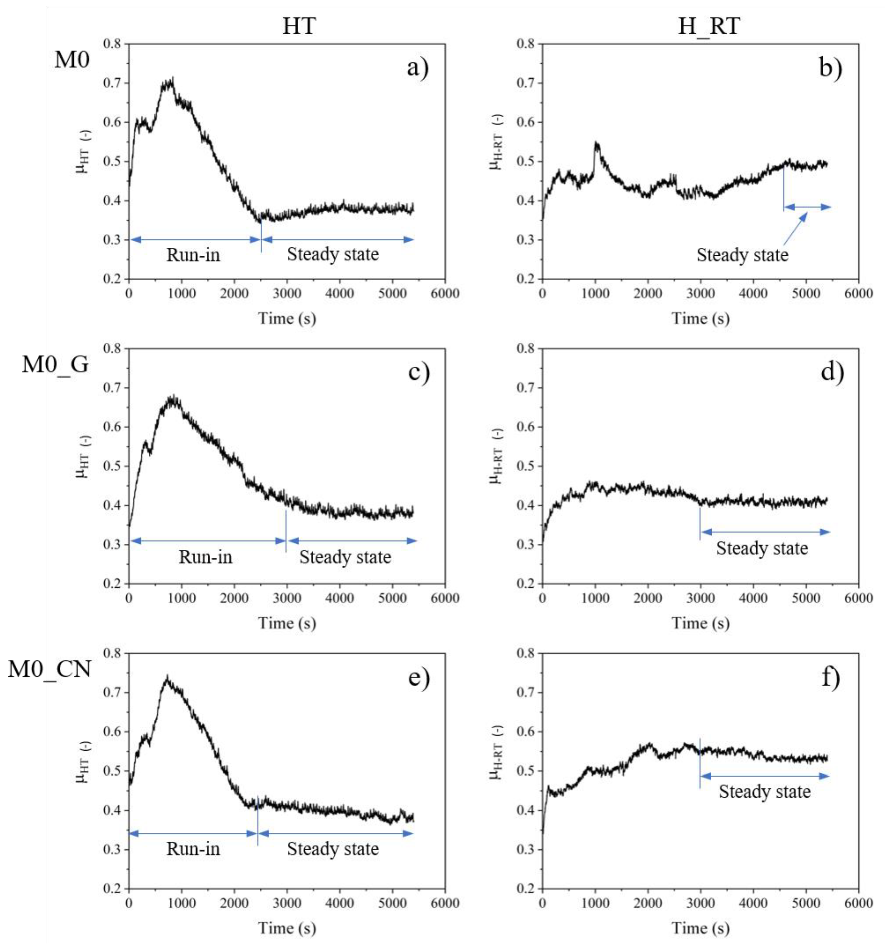
3.4. Friction and Wear Behaviour of the Samples at HT and Recovery of Their Friction-Wear Performance

Figure 6 shows the evolution of µ obtained from the tests conducted at HT and again at RT after the HT tests (H_RT). At HT, a peculiar run-in stage was observed for all three samples. It was characterised by an increase in µHT with the attainment of a peak value, after which µHT decreased to reach a steady state value after 2000–3000 s of sliding. Similar behaviour was reported by Leonardi et al. [40]. The steady-state values of µHT were in the range of 0.37–0.38, independent of the material (Table 4), and these values were lower than the values obtained at RT.
During the subsequent H_RT tests (Figure 6), which indicated the ability of the friction composites to recover the friction performance, the µH_RT values obtained for all samples (i.e., M0, M0_G and M0_CN) exceeded the µHT values obtained for those samples during HT tests (Table 4). As shown in the figure, the friction coefficient curve of M0 during the H_RT test exhibited a long run-in stage, featuring large fluctuations in the friction trace, whereas M0_G had a stable but lower value of µH_RT. The best behaviour during the H_RT tests was displayed by M0_CN, which showed an initial increase in µ, followed by steady-state conditions at a high value of 0.49 (Table 4).
The Ka values for the H_RT tests are also listed in Table 4. For M0, an increase in the wear rate compared to the value obtained at HT was observed. The same comparison showed a reduction of Ka in the case of M0_G, whereas for M0_CN, comparable Ka values were obtained under both H_RT and HT test conditions (Table 4).

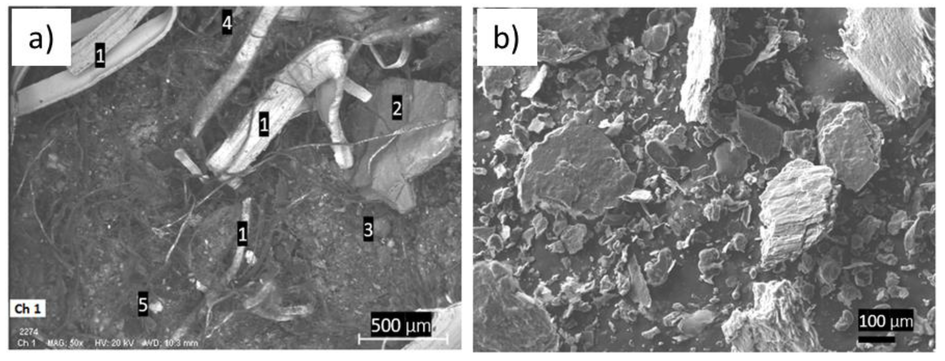
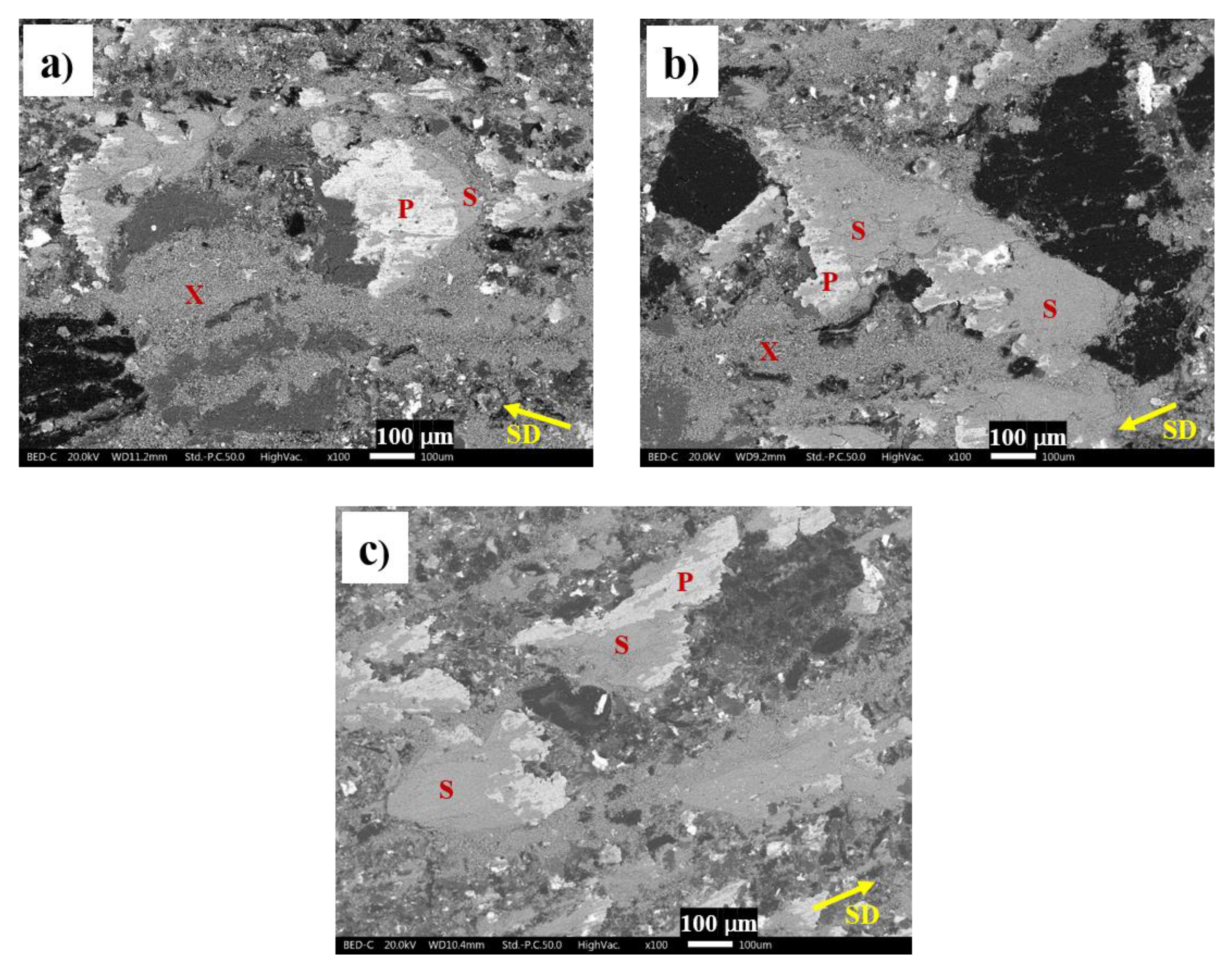
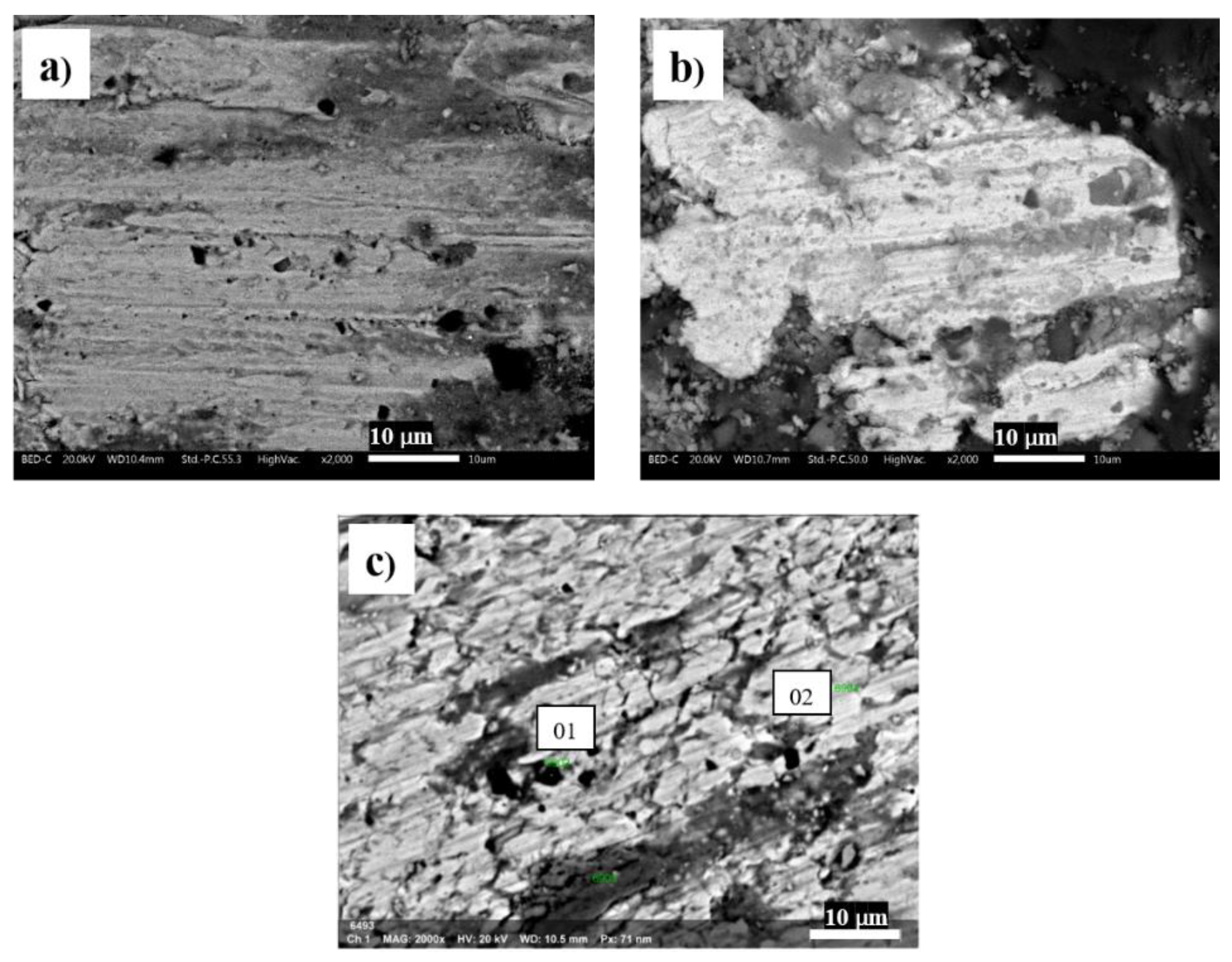
3.5. Analysis of Worn Surfaces

SEM micrographs of the worn surfaces obtained for the samples after the test at RT are shown in Figure 7a–c. Figure 7 shows the worn surfaces of the tested materials observed at the end of the relevant PoD tests under RT conditions. All the samples displayed a typical friction layer made of primary plateaus (mainly steel fibres) that blocked the wear fragments and, thus, promoted the formation of secondary plateaus. The friction surface of M0 consisted of small secondary plateaus and many wear particles that were not well compacted and were dispersed onto the surface (indicated as X in the micrographs in Figure 7). The worn surface of M0_G showed larger and more compacted secondary plateaus coexisting with poorly compacted wear fragments, again marked as X. The worn surface of M0_CN showed the presence of primary and secondary plateaus. The secondary plateaus of M0_CN were well compacted and did not display regions of loosened fragments of wear particles.
EDXS analyses were conducted to evaluate the elemental composition of the secondary plateaus, and the results are presented in Table 5. As expected, the dominant element forming the secondary contact plateaus was iron that originated from the wear of the steel fibres and, most importantly, from the wear of the cast iron disc.
Table 5 shows the lowest iron content for M0_CN. The carbon content increased in the order: M0, M0_G and M0_CN. The higher amount of carbon in M0_G with respect to M0 owed to the addition of graphite, which is known to enter the friction layer [40]. In the case of M0_CN, the larger content of carbon in the secondary plateaus, compared to both M0 and M0_G, can be ascribed to gCN, which, similar to graphite, tended to enter the secondary plateaus. This was also confirmed by the presence of nitrogen detected in the secondary plateaus of M0_CN. It should be noted that some of the detected carbon may also have come from the decomposition of organic ingredients of the friction materials, such as the phenolic binder and rubber fragments.
The characteristics of the primary plateaus formed by the steel fibres were also examined in detail, and Figure 8 shows the worn surfaces of the steel fibres.
Large plastic deformation in the direction of sliding was observed in all cases. However, the presence of cracks perpendicular to the sliding direction were also observed to be on the surface of the steel fibres of M0_CN. Higher magnification images and microanalytical data confirmed the piling up of wear particles inside these cracks. The EDXS analyses (see Table 6) confirmed the presence of small and agglomerated SiC and gCN particles.

3.6. Discussion on the Role of Studied Lubricants on Friction-Wear Performance

To better understand the role of graphite and graphitic carbon nitride particles on the tribological behaviour of the investigated friction materials, the µ and Ka values obtained from the PoD tests are summarised in Figure 9a,b.
Graphite is generally used as a solid lubricant in friction materials. It has a lamellar structure that tends to exfoliate between the sliding surfaces, so that small flakes of graphite enter the secondary plateaus [8,30]. SEM observations were conducted on the friction surfaces of the worn pins (Figure 7), and it was revealed that M0_G showed the presence of better-compacted secondary plateaus rich in carbon (Table 5) compared to the reference material M0 (the sample without graphite). Graphite that is localised in secondary plateaus provides smooth sliding friction and, at the same time, protects the mating surfaces from severe wear. In fact, the lower local friction stress resulting from the presence of graphite reduces the possibility of wear owing to the disruption of the friction layers [8]. Compared to the other tested formulations, M0_G had the lowest value of μ and Ka under all testing conditions.
During the HT tests, all the materials displayed similar friction and wear behaviour (Figure 9). The presence of a peak in the friction coefficient during running-in (Figure 6) was also observed in previous investigations [46] and is attributed to the formation and disruption of an oxidised layer on the disc surface [47]. This also explains the similar behaviour of all three tested friction composites. After the oxidised layer was removed, the friction coefficient decreased, because the softening of the friction material at high temperature was induced by the degradation of the phenolic resin [48].
During subsequent RT tests (H-RT), the friction coefficient increased again as a result of friction layer formation. This test indicates the ability of the friction surface to recover the friction performance. However, the recovery in the friction coefficient was rather limited, most probably because of the limited formation of secondary plateaus as already explained Leonardi et al. [46]. This is particularly true in the case of M0 and M0_G (Figure 6b,d, respectively). This is attributed to the insufficient presence of abrasive particles able to wear the counterface disc, resulting in the production of lower amounts of wear fragments needed for the formation of secondary plateaus.
Similar to graphite, gCN particles also have a lamellar structure, but from the results of the PoD tests (Figure 5 and Figure 6) and the characteristics of the worn surfaces (Figure 7 and Figure 8), the gCN particles behaved as a mild abrasive. In fact, the addition of this constituent increased the value of µRT, which can be attributed to the additional abrasive action exerted by the gCN particles embedded into the steel fibres (Figure 8). A similar observation for SiC particles was reported by Matějka et al. [49]. The gCN particles embedded into the steel fibres also reduced the ductility of the fibres, thus favouring the formation of cracks as shown in Figure 8. As already shown in Figure 7, the presence of gCN had a positive effect on the formation of compact secondary contact plateaus in contrast to the M0 and M0_G composites, for which large areas of non-compacted wear particles is a typical feature. The effect of graphite and gCN particle size on the formation of larger areas of well-compacted secondary contact plateaus should not be omitted. Leonardi et al. [40] showed that finer graphite particles have a positive effect on well-compacted secondary contact plateaus. When comparing Figure 1a and Figure 2b the finer morphology of the gCN particles is obvious. The friction process caused the fragmentation of gCN particles to even smaller debris which, in contrast to larger graphite particles, easily become part of the secondary contact plateaus. It is evident that the gCN showed additional functionality as a compact secondary layer-forming agent. It has to be mentioned that non-compacted wear particles can be a source of airborne particles [50] and, thus, the presence of gCN could help to reduce wear particle emissions as well; this functionality needs to be confirmed by further research. The multiple functionalities of the components were also observed, for example, for barite [51,52], which is usually considered only as a space filler.
The wear coefficient (Ka) of M0_CN at RT was higher than that of M0_G (Figure 9b) because of the presence of the mild gCN abrasive particles and absence of graphite solid lubricant. On the other hand, the Ka value of M0_CN was similar to that of the reference material M0. The same trend was observed under the HT testing conditions (Figure 9b). The Ka value of M0_CN was intermediate between those of M0 and M0_G, but the friction coefficient of M0_CN was much higher (Figure 9a). This confirms the mild abrasive character of the gCN particles embedded into the steel fibres, and their abrasive ability was maintained even after the HT tests. In particular, the effect of gCN on the friction performance seems to be more effective than that of SiC particles, which were also present in the other two materials. This can be explained by considering that embedding of relatively coarse SiC particles into steel fibres requires their preliminary fragmentation [39]. In contrast, the finer gCN particles were promptly trapped on the surface of the steel fibres and acted as abrasives from the beginning of the friction tests.

4. Conclusions

The role of gCN was investigated in comparison with that of graphite in a Cu-free friction material. Pin-on-disc tests were conducted to study the tribological behaviour of the samples under different conditions. The following conclusions were drawn from the experimental results and analyses.
The prepared gCN had a lamellar structure similar to that of graphite, but it behaved as a mild abrasive in friction materials.
Under RT testing conditions, the addition of graphite to the reference formulation reduced the friction coefficient (from 0.50 to 0.46) and wear rate (from 6.65·10−14 m2·N−1 to 3.85·10−14 m2·N−1), whereas the addition of gCN increased the friction coefficient (from 0.50 to 0.52) but did not increase the wear rate (6.56·10−14 m2·N−1 vs. 6.57·10−14 m2·N−1).
The friction composite with gCN showed the best recovery of the friction coefficient after the test at high temperature showing a difference if only −0.03. Regarding the specific wear rate, the composite with graphite showed the best recovery after the test at high temperature (3.85·10−14 m2·N−1 vs. 4.44·10−14 m2·N−1).
M0_CN exhibited good friction coefficient recovery properties compared to the M0 and M0_G samples.
Further investigation should be conducted on the simultaneous addition of graphite and gCN with the aim of producing a material with a high and stable friction coefficient but a lower wear rate. Another research stream could be the modification of the g-C3N4 material by exfoliation and verification if such treatment would change the role of g-C3N4 in terms of the lubricating effect.

Author Contributions

Investigation, V.M. and M.L.; Writing—Original Draft, V.M. and M.L.; Discussion, G.S. and S.G.; Writing—Review and Editing, P.P., G.S., and S.G.; Conceptualization, V.M., G.S., and S.G.; Data Treatment, M.L. and V.M.; Methodology, G.S. and S.G.; Software, M.L. and V.M.; Validation, M.L.; Resources, P.P.; Supervision, G.S. and S.G.; Funding acquisition, P.P. All authors have read and agreed to the published version of the manuscript.

Funding

The authors thank the Czech Science Foundation (project No. 19-15199S), EU Structural Funding in Operational Programme Research, Development and Education (project No. CZ.02.1.01/0.0/0.0/16_019/0000853 “IET-ER”) and VŠB-TU Ostrava (project No. SP2021/46) for the financial support.

Institutional Review Board Statement

Not applicable.

Informed Consent Statement

Not applicable.

Data Availability Statement

Data presented in this study are available on request from the corresponding author.

Acknowledgments

The authors thank Brembo Company for providing the master batch.

Conflicts of Interest

The authors declare no conflict of interest.

References

  1. Cox, R.L. Engineered Tribological Composites: The Art of Friction Material Development; SAE International: Warrendale, PA, USA, 2011; p. 524. [Google Scholar]
  2. Xiao, Y.; Yao, P.; Zhou, H.; Zhang, Z.; Gong, T.; Zhao, L.; Deng, M. Investigation on Speed-Load Sensitivity to Tribological Properties of Copper Metal Matrix Composites for Braking Application. Metals 2020, 10, 889. [Google Scholar] [CrossRef]
  3. Lyu, Y.; Leonardi, M.; Mancini, A.; Wahlström, J.; Olofsson, U. Tribology and Airborne Particle Emission of Laser-Cladded Fe-Based Coatings versus Non-Asbestos Organic and Low-Metallic Brake Materials. Metals 2021, 11, 1703. [Google Scholar] [CrossRef]
  4. Seo, H.; Park, J.; Kim, Y.C.; Lee, J.J.; Jang, H. Effect of disc materials on brake emission during moderate-temperature braking. Tribol. Int. 2021, 163, 107185. [Google Scholar] [CrossRef]
  5. Matějka, V.; Metinöz, I.; Wahlström, J.; Alemani, M.; Perricone, G. On the running-in of brake pads and discs for dyno bench tests. Tribol. Int. 2017, 115, 424–431. [Google Scholar] [CrossRef]
  6. Chan, D.; Stachowiak, G.W. Review of automotive brake friction materials. Proc. Inst. Mech. Eng. Part D J. Automob. Eng. 2004, 218, 953–966. [Google Scholar] [CrossRef]
  7. Fan, Y.; Matějka, V.; Kratošová, G.; Lu, Y. Role of Al2O3 in Semi-Metallic Friction Materials and its Effects on Friction and Wear Performance. Tribol. Trans. 2008, 51, 771–778. [Google Scholar] [CrossRef]
  8. Matejka, V.; Lu, Y.F.; Jiao, L.; Huang, L.; Martynkova, G.S.; Tomasek, V. Effects of silicon carbide particle sizes on friction-wear properties of friction composites designed for car brake lining applications. Tribol. Int. 2010, 43, 144–151. [Google Scholar] [CrossRef]
  9. Ma, Y.; Martynková, G.S.; Valášková, M.; Matějka, V.; Lu, Y. Effects of ZrSiO4 in non-metallic brake friction materials on friction performance. Tribol. Int. 2008, 41, 166–174. [Google Scholar] [CrossRef]
  10. Park, J.; Song, W.; Gweon, J.; Seo, H.; Lee, J.J.; Jang, H. Size effect of zircon particles in brake pads on the composition and size distribution of emitted particulate matter. Tribol. Int. 2021, 160, 106995. [Google Scholar] [CrossRef]
  11. Aranganathan, N.; Bijwe, J. Special grade of graphite in NAO friction materials for possible replacement of copper. Wear 2015, 330, 515–523. [Google Scholar] [CrossRef]
  12. Matějka, V.; Lu, Y.; Matějková, P.; Smetana, B.; Kukutschová, J.; Vaculík, M.; Tomášek, V.; Zlá, S.; Fan, Y. Possible stibnite transformation at the friction surface of the semi-metallic friction composites designed for car brake linings. Appl. Surf. Sci. 2011, 258, 1862–1868. [Google Scholar] [CrossRef] [Green Version]
  13. Österle, W.; Dmitriev, A.I. The Role of Solid Lubricants for Brake Friction Materials. Lubricants 2016, 4, 5. [Google Scholar] [CrossRef] [Green Version]
  14. Lin, H.-Y.; Cheng, H.-Z.; Lee, K.-J.; Wang, C.-F.; Liu, Y.-C.; Wang, Y.-W. Effect of Carbonaceous Components on Tribological Properties of Copper-Free NAO Friction Material. Materials 2020, 13, 1163. [Google Scholar] [CrossRef] [Green Version]
  15. Matějka, V.; Fu, Z.; Kukutschová, J.; Qi, S.; Jiang, S.; Zhang, X.; Yun, R.; Vaculík, M.; Heliová, M.; Lu, Y. Jute fibers and powderized hazelnut shells as natural fillers in non-asbestos organic non-metallic friction composites. Mater. Des. 2013, 51, 847–853. [Google Scholar] [CrossRef]
  16. Baklouti, M.; Cristol, A.L.; Desplanques, Y.; Elleuch, R. Impact of the glass fibers addition on tribological behavior and braking performances of organic matrix composites for brake lining. Wear 2015, 330, 507–514. [Google Scholar] [CrossRef]
  17. Matějka, V.; Perricone, G.; Vlček, J.; Olofsson, U.; Wahlström, J. Airborne Wear Particle Emissions Produced during the Dyno Bench Tests with a Slag Containing Semi-Metallic Brake Pads. Atmosphere 2020, 11, 1220. [Google Scholar] [CrossRef]
  18. Handa, Y.; Kato, T. Effects of Cu Powder, BaSO4 and Cashew Dust on the Wear and Friction Characteristics of Automotive Brake Pads. Tribol. Trans. 1996, 39, 346–353. [Google Scholar] [CrossRef]
  19. Österle, W.; Prietzel, C.; Kloß, H.; Dmitriev, A.I. On the role of copper in brake friction materials. Tribol. Int. 2010, 43, 2317–2326. [Google Scholar] [CrossRef]
  20. Hong, U.S.; Jung, S.L.; Cho, K.H.; Cho, M.H.; Kim, S.J.; Jang, H. Wear mechanism of multiphase friction materials with different phenolic resin matrices. Wear 2009, 266, 739–744. [Google Scholar] [CrossRef]
  21. Jara, D.C.; Jang, H. Synergistic effects of the ingredients of brake friction materials on friction and wear: A case study on phenolic resin and potassium titanate. Wear 2019, 430, 222–232. [Google Scholar] [CrossRef]
  22. Abutu, J.; Lawal, S.A.; Ndaliman, M.B.; Lafia-Araga, R.A.; Adedipe, O.; Choudhury, I.A. Effects of process parameters on the properties of brake pad developed from seashell as reinforcement material using grey relational analysis. Eng. Sci. Technol. Int. J. 2018, 21, 787–797. [Google Scholar] [CrossRef]
  23. Cho, M.H.; Kim, S.J.; Kim, D.; Jang, H. Effects of ingredients on tribological characteristics of a brake lining: An experimental case study. Wear 2005, 258, 1682–1687. [Google Scholar] [CrossRef]
  24. Surya Rajan, B.; Sai Balaji, M.A.; Mohamed Aslam Noorani, A.B.M.A. Tribological performance of graphene/graphite filled phenolic composites-A comparative study. Compos. Commun. 2019, 15, 34–39. [Google Scholar]
  25. Bijwe, J.; Aranganathan, N.; Sharma, S.; Dureja, N.; Kumar, R. Nano-abrasives in friction materials-influence on tribological properties. Wear 2012, 296, 693–701. [Google Scholar] [CrossRef]
  26. Mahale, V.; Bijwe, J.; Sinha, S. Influence of nano-potassium titanate particles on the performance of NAO brake-pads. Wear 2017, 376, 727–737. [Google Scholar] [CrossRef]
  27. Antonyraj, I.J.; Singaravelu, D.L. Tribological characterization of various solid lubricants based copper-free brake friction materials–A comprehensive study. Mater. Today Proc. 2020, 27, 2650–2656. [Google Scholar] [CrossRef]
  28. Kalel, N.; Bhatt, B.; Darpe, A.; Bijwe, J. Copper-free brake-pads: A break-through by selection of the right kind of stainless steel particles. Wear 2021, 464, 203537. [Google Scholar] [CrossRef]
  29. Aranganathan, N.; Bijwe, J. Development of copper-free eco-friendly brake-friction material using novel ingredients. Wear 2016, 352, 79–91. [Google Scholar] [CrossRef]
  30. Bhatt, B.; Kalel, N.; Darpe, A.; Bijwe, J. Role of Promaxon-D in Controlling Tribological Performance of Cu-Free Brake Pads. Metals 2021, 11, 441. [Google Scholar] [CrossRef]
  31. Mamba, G.; Mishra, A.K. Graphitic carbon nitride (g-C3N4) nanocomposites: A new and exciting generation of visible light driven photocatalysts for environmental pollution remediation. Appl. Catal. B 2016, 198, 347–377. [Google Scholar] [CrossRef]
  32. Yin, L.; Cheng, R.; Song, Q.; Yang, J.; Kong, X.; Huang, J.; Lin, Y.; Ouyang, H. Construction of nanoflower SnS2 anchored on g-C3N4 nanosheets composite as highly efficient anode for lithium ion batteries. Electrochim. Acta 2019, 293, 408–418. [Google Scholar] [CrossRef]
  33. Das, D.; Shinde, S.; Nanda, K. Temperature-dependent photoluminescence of g-C3N4: Implication for temperature sensing. ACS Appl. Mater. Interfaces 2016, 8, 2181–2186. [Google Scholar] [CrossRef] [PubMed]
  34. Inagaki, M.; Tsumura, T.; Kinumoto, T.; Toyoda, M. Graphitic carbon nitrides (g-C3N4) with comparative discussion to carbon materials. Carbon 2019, 141, 580–607. [Google Scholar] [CrossRef]
  35. Reddy, K.R.; Reddy, C.H.V.; Nadagouda, M.N.; Shetti, N.P.; Jaesool, S.; Aminabhavi, T.M. Polymeric graphitic carbon nitride (g-C3N4)-based semiconducting nanostructured materials: Synthesis methods, properties and photocatalytic applications. J. Environ. Manag. 2019, 238, 25–40. [Google Scholar] [CrossRef]
  36. Praus, P.; Svoboda, L.; Ritz, M.; Troppová, I.; Šihor, M.; Kočí, K. Graphitic carbon nitride: Synthesis, characterization and photocatalytic decomposition of nitrous oxide. Mater. Chem. Phys. 2017, 193, 438–446. [Google Scholar] [CrossRef]
  37. Zhu, L.; You, L.; Shi, Z.; Song, H.; Li, S. An investigation on the graphitic carbon nitride reinforced polyimide composite and evaluation of its tribological properties. J. Appl. Polym. Sci. 2017, 134, 45403. [Google Scholar] [CrossRef]
  38. Duan, C.; Yuan, D.; Yang, Z.; Li, S.; Tao, L.; Wang, Q.; Wang, T. High wear-resistant performance of thermosetting polyimide reinforced by graphitic carbon nitride (g-C3N4) under high temperature. Compos. Part A 2018, 113, 200–208. [Google Scholar] [CrossRef]
  39. Zhang, L.; Li, G.; Guo, Y.; Qi, H.; Che, Q.; Zhang, G. PEEK reinforced with low-loading 2D graphitic carbon nitride nanosheets: High wear resistance under harsh lubrication conditions. Compos. Part A 2018, 109, 507–516. [Google Scholar] [CrossRef]
  40. Leonardi, M.; Alemani, M.; Straffelini, G.; Gialanella, S. A pin-on-disc study on the dry sliding behavior of a Cu-free friction material containing different types of natural graphite. Wear 2020, 442, 203157. [Google Scholar] [CrossRef]
  41. Praus, P.; Smykalova, A.; Fonioka, K.; Matejka, V.; Kormunda, M.; Smetana, B.; Cvejn, D. The presence and effect of oxygen in graphitic carbon nitride synthetized in air and nitrogen atmosphere. Appl. Surf. Sci. 2020, 529, 10. [Google Scholar] [CrossRef]
  42. Nasir, M.S.; Yang, G.; Ayub, I.; Wang, S.; Wang, L.; Wang, X.; Yan, W.; Peng, S.; Ramakarishna, S. Recent development in graphitic carbon nitride based photocatalysis for hydrogen generation. Appl. Catal. B 2019, 257, 117855. [Google Scholar] [CrossRef]
  43. Pan, H.; Zhang, H.; Liu, H.; Chen, L. Interstitial boron doping effects on the electronic and magnetic properties of graphitic carbon nitride materials. Solid State Commun. 2015, 203, 35–40. [Google Scholar] [CrossRef]
  44. Han, Q.; Hu, C.; Zhao, F.; Zhang, Z.; Chen, N.; Qu, L. One-step preparation of iodine-doped graphitic carbon nitride nanosheets as efficient photocatalysts for visible light water splitting. J. Mater. Chem. A 2015, 3, 4612–4619. [Google Scholar] [CrossRef]
  45. Dong, G.; Ai, Z.; Zhang, L. Efficient anoxic pollutant removal with oxygen functionalized graphitic carbon nitride under visible light. RSC Adv. 2014, 4, 5553–5560. [Google Scholar] [CrossRef]
  46. Leonardi, M.; Menapace, C.; Matějka, V.; Gialanella, S.; Straffelini, G. Pin-on-disc investigation on copper-free friction materials dry sliding against cast iron. Tribol. Int. 2018, 119, 73–81. [Google Scholar] [CrossRef]
  47. Verma, P.C.; Ciudin, R.; Bonfanti, A.; Aswath, P.; Straffelini, G.; Gialanella, S. Role of the friction layer in the high-temperature pin-on-disc study of a brake material. Wear 2016, 346, 56–65. [Google Scholar] [CrossRef]
  48. Menapace, C.; Leonardi, M.; Secchi, M.; Bonfanti, A.; Gialanella, S.; Straffelini, G. Thermal behavior of a phenolic resin for brake pad manufacturing. J. Therm. Anal. Calorim. 2019, 137, 759–766. [Google Scholar] [CrossRef]
  49. Matějka, V.; Lu, Y.; Fan, Y.; Kratošová, G.; Lešková, J. Effects of silicon carbide in semi-metallic brake materials on friction performance and friction layer formation. Wear 2008, 265, 1121–1128. [Google Scholar] [CrossRef]
  50. Lyu, Y.; Leonardi, M.; Wahlström, J.; Gialanella, S.; Olofsson, U. Friction, wear and airborne particle emission from Cu-free brake materials. Tribol. Int. 2020, 141, 105959. [Google Scholar] [CrossRef]
  51. Kumar, M.; Bijwe, J. Non-asbestos organic (NAO) friction composites: Role of copper; its shape and amount. Wear 2011, 270, 269–280. [Google Scholar] [CrossRef]
  52. Menapace, C.; Leonardi, M.; Matějka, V.; Gialanella, S.; Straffelini, G. Dry sliding behavior and friction layer formation in copper-free barite containing friction materials. Wear 2018, 398, 191–200. [Google Scholar] [CrossRef]
Figure 1. SEM micrographs: (a) reference masterbatch (M0) with some identified constituents (1—steel fibre, 2—vermiculite, 3—aluminium oxide, 4—magnesium oxide and 5—tin sulphide); (b) synthetic graphite particles in the M0_G formulation.
Metals 12 00123 g001
Figure 2. SEM micrographs of gCN powder: (a) image of the typical gCN particle; (b) details of the pores observed on the gCN surface.
Metals 12 00123 g002
Figure 3. (a) Diffraction pattern of gCN sample and (b) FTIR spectra of the gCN sample.
Metals 12 00123 g003
Figure 4. (a) TG curves for components G and gCN and (b) for friction mixtures M0, M0_G and M0_CN.
Metals 12 00123 g004
Figure 5. Evolution of the friction coefficient at RT for the (a) M0, (b) M0_G and (c) M0_CN samples. The red, dotted parts of the curves indicate the relevant steady state.
Metals 12 00123 g005
Figure 6. Evolution of the µ with time for the materials tested at high temperature (HT) and at RT after the HT tests (H_RT). (a,b) smaple M0, (c,d) M0_G, and (e,f) M0_CN).
Metals 12 00123 g006
Figure 7. SEM micrographs showing the surfaces of the pins after the PoD tests at RT: (a) M0, (b) M0_G and (c) M0_CN. P—primary plateaus; S—secondary plateaus; X—non-compacted wear particles; SD—sliding direction.
Metals 12 00123 g007
Figure 8. SEM micrographs of the steel fibres present on the surfaces of the pins that worked as primary plateaus: (a) M0, (b) M0_G and (c) M0_CN. The numbers 01 and 02 show the positions of the local EDX analysis (Table 6).
Metals 12 00123 g008
Figure 9. Comparison of (a) µ values and (b) Ka values obtained during the tests at RT, HT and H_RT.
Metals 12 00123 g009
Table 1. Main components of M0, their roles, and estimated contents in the reference masterbatch without graphite.
Constituents of M0Main RoleContent (wt.%)
SteelReinforcing fibres30
Aluminium oxide, silicon carbide, and magnesium oxideAbrasives25
Tin sulphide, sphalerite, and zinc oxideLubricants13
Vermiculite and othersFillers24
Phenolic resinBinder8
Table 2. Particle size distribution of the synthetic graphite (sieving analysis).
Fraction content0.4%23%37%72%91%
Fraction size>800 µm>600 µm>550 µm>250 µm>150 µm
Table 3. EDXS spectra acquired on the gCN powder.
ElementsCNAlO
Content (wt.%)44.941.112.11.9
Table 4. Experimental results of the PoD tests at room temperature (RT), high temperature (HT) and at room temperature after the HT tests (H_RT): coefficient of friction (µ) and specific wear coefficient (Ka).
Sampleµ (-)Ka (×10−14 m2/N)
RTHTH_RTRTHTH_RT
M00.50 ± 0.040.38 ± 0.010.43 ± 0.066.56 ± 1.2210.44 ± 0.9315.65 ± 2.19
M0_G0.46 ± 0.010.37 ± 0.010.39 ± 0.023.85 ± 0.378.02 ± 0.524.44 ± 1.58
M0_CN0.52 ± 0.010.37 ± 0.040.49 ± 0.046.57 ± 0.0811.10 ± 0.2112.20 ± 0.42
Table 5. Elemental composition (EDXS) of secondary plateaus on the pin surfaces.
Element (wt.%)M0M0_GM0_CN
Fe60.1960.054.76
C6.728.919.73
Zn4.413.594.94
Al2.122.212.23
Mg2.122.272.26
Sn2.062.542.98
S1.842.382.70
Si1.231.361.02
N--1.18
Cr0.960.980.88
Ca0.710.810.92
O17.6714.9316.42
Table 6. Point EDXS analysis on the worn steel fibres of M0_CN (see relevant SEM micrograph in Figure 8).
Content
Wt.%
Point
0102
Si57.61-
C28.465.64
Fe12.0793.59
O1.86-
N-0.77
Publisher’s Note: MDPI stays neutral with regard to jurisdictional claims in published maps and institutional affiliations.

