Article

Study on the Mechanical Performance of Dissimilar Butt Joints between Low Ni Medium-Mn and Ni-Cr Austenitic Stainless Steels Processed by Gas Tungsten Arc Welding

1
Mechanical Engineering Department, Faculty of Engineering at Shoubra, Benha University, Cairo 11629, Egypt
2
Central Metallurgical Research and Development Institute (CMRDI), Helwan 11722, Egypt
3
Kerttu Saalasti Institute, Future Manufacturing Technologies (FMT), University of Oulu, FI-85500 Nivala, Finland
*
Authors to whom correspondence should be addressed.
Metals 2021, 11(9), 1439; https://doi.org/10.3390/met11091439
Submission received: 30 July 2021 / Revised: 3 September 2021 / Accepted: 9 September 2021 / Published: 13 September 2021
(This article belongs to the Special Issue Welded and Adhesive Joints for Marine Applications)

Abstract

:
In the present work, dissimilar butt joints between a low-Ni, medium-Mn austenitic stainless steel, M-Mn SS, and a Ni-Cr austenitic stainless steel, Ni-Cr SS, were processed by utilizing the gas tungsten arc welding (GTAW) technique at different heat inputs. A filler metal of ER308 was employed in the welding process. The filler yields 480 MPa, which is equivalent to the yield strength of M-Mn SS. The microstructural analysis and mechanical performance (i.e., tensile strength and hardness properties) of the concerned joints were studied by using an optical microscope and uniaxial tensile tests, respectively. The results revealed that a duplex structure from austenite matrix and delta ferrite is promoted in the fusion zone (FZ) of the dissimilar joints processed with low and high energy inputs (0.486 kJ/mm and 0.558 kJ/mm). The FZ of the specimens welded at high heat input exhibited the lowest hardness value (151.2 HV) in comparison to heat affected zone (HAZ) (166.3 HV). Moreover, the joints exhibited a low tensile strength of 610 MPa. The achieved strength is significantly lower than the strengths of the base metals (BMs) M-Mn SS and Ni-Cr SS. This is mainly attributed to the inhomogeneous dendritic structure of the FZ with Cr-carbides precipitation.

1. Introduction

Austenitic stainless steels (ASSs) are widely used in many industrial applications such as automotive, chemical, petrochemical, marine structure, steel structure, and furniture industries [1]. ASS has excellent formability, superior mechanical properties such as strength and ductility, oxidation resistance at elevated temperatures, and high corrosion resistance [2]. The typical chemical composition of ASSs 300 series contains 18–26 wt.% Cr and 8–37 wt.% Ni, in addition to low C content ranges (0.03–0.25 wt.%) [3]. Ni is responsible for stabilizing the austenitic microstructure at room temperature; however, it increases the cost of alloy. Mn is combined with N to produce the same effect of Ni as an austenitic stabilizer with low cost [4]. Moreover, the N addition enhances the austenite phase range, it improves mechanical properties, and promotes the passivation process, resulting in improvements of corrosion resistance properties [5]. Cr-Mn stainless steels are developed under a new grade of austenitic stainless steels called the 200 series, reducing Ni content to less than 1 wt.% to meet market needs with higher quality and lower cost compared to the ASSs 300 series [4,6]. Cr alloying element is the responsible element for developing corrosion resistance of ASS [7]. Therefore, Cr-Mn SS (200 series) naturally possesses lower corrosion resistance compared to Cr-Ni SS (300 series) due to the low content of Cr and Ni alloying elements. The N addition presents in Cr-Mn SS in order to improve the corrosion resistance of these alloys [8].
The interest of the 200 series stainless steels, due to their greater mechanical resistance compared to the 300 series stainless steels, has existed since many years [4]. It is well known that dissimilar weld joints involve various paired metals with different chemical compositions, mechanical properties, and microstructures. Hence, an inhomogeneous microscopic structure of the dissimilar joints with considerable residual stresses and intermetallic compounds is induced. The residual stresses developed during the joining of the dissimilar metals may induce the premature failure of the components under service [9]. Furthermore, the heterogeneous microstructure with undesired delta ferrite is formed along the fusion zone. This structure may reduce the dissimilar joints’ mechanical strength, impact toughness, microhardness, and corrosion resistance [10,11,12]. However, the existence of delta-ferrite (3–10 volume %) in the austenitic matrix of the FZ plays an essential role in avoiding the formation of solidification cracks, as well as the enhancement of ductility, toughness, and corrosion resistance [13,14,15,16]. Moreover, the selection of proper electrodes and welding parameters are essential factors for achieving the optimum mechanical properties, microstructures, corrosion resistance, and quality of the weld bead shape [17]. The existence of Mn, Mo, and lesser content of S in the filler metals decreases the susceptibility of solidification cracks [18]. Bansod et al. [18] and Keshari et al. [19] investigated the effect of different filler metals on the microstructure and mechanical properties of Cr-Mn SS and AISI 304 SS weld metals. It has been found that the 308L and 316L filler metals resulted in the formation of austenite matrix and delta-ferrite in the FZ. However, 308L filler metal showed higher tensile strength and ductility than the 316L filler metal. Chuaiphan et al. [20] reported that the 316L and 309L filler metals produced austenite matrix and delta-ferrite in the FZ of 204Cu SS and 304 SS weld metal. Furthermore, the tensile strength and ductility of the weld metal (WM) increased when 316L filler metal is used instead of 309L filler metal.
Fusion joining techniques can result in changes in the weld metal’s chemical composition, which affects the stability of the Cr2O3 passive layer and its corrosion resistance due to the thermal cycles induced during the welding process [21]. Moreover, carbides precipitation, second intermetallic phases, and inclusions are prone to inducing pitting corrosion [7,22]. In the open literature, shielded metal arc welding (SMAW) and gas tungsten arc welding (GTAW) techniques were employed to weld a Cr-Ni stainless steel, a grade of 300 series, and a Cr-Mn stainless steel, which is a grade of 200 series. However, GTAW is the recommended process due to its reliability, superior mechanical properties, and corrosion resistance compared with the weldments produced by the SMAW process [23]. Vashishtha et al. [24] studied the effect of SMAW and GTAW techniques on the dissimilar welding of AISI 304 and AISI 201 austenitic stainless steels using a filler metal of 308L. They reported that the joints welded by the GTAW technique exhibited higher mechanical strength compared to the joints welded by SMAW technique. Shielding gas plays a vital role in the microstructures, corrosion resistance, and weld quality. It was found that N mixed with Ar shielding gas (0 to 12% vol.) decreased the amount of delta-ferrite from 20 to 16% vol. in the austenite matrix after dissimilar welding of 201 SS and 304 SS [25]. It was also found that the hydrogen mixed with Ar shielding gas for similar welding of 316L SS increased the mean grain size, tensile strength, weld metal penetration, and weld bead width [26].
The mechanical properties and microstructure of ASSs weld metal depend on the heat input used. Kumar et al. [27] studied the effects of different heat inputs on the mechanical properties and microstructure of 304 SS weld metal. It was found that the heat input increase resulted in a decrease in the strength, ductility, and hardness in the FZ. Moreover, the dendrite length increased in the FZ. Chuaiphan et al. [28] investigated the increase in welding speed on the mechanical behavior, microstructure, and corrosion resistance of Cr-Mn SS (AISI 201) weld metals. It was found that as the welding speed decreased (heat input increased), the tensile properties and the hardness decreased. Moreover, the amount of embedded delta-ferrite decreased in the austenitic matrix at the high welding speed (low heat input) since the cooling rate was relatively high, which provided an amount of short time for dendrites’ formation and growth in the FZ. Taiwade et al. [29] reported the existence of carbide precipitation, and grain coarsening increased with an increase in passes relative to the number of similar welding of 304 SS and Cr-Mn SS. It was found that the tensile strength decreased with an increase in passes number.
Dissimilar welding of medium-Mn stainless steel with another steel is scarcely investigated. However, Chuaiphan and Srijaroenpramong [20] studied the mechanical properties and corrosion behavior of dissimilar joints 204Cu and 304 by GTA with one heat input. The purpose of the present paper is to comprehensively investigate the dissimilar weldability of M-Mn SS with Ni-Cr SS by applying the welding technique, GTAW, at different heat inputs. The microstructure evolution, mechanical tensile strength, and hardness properties of the weldments were depicted in order to determine the welding efficacy.

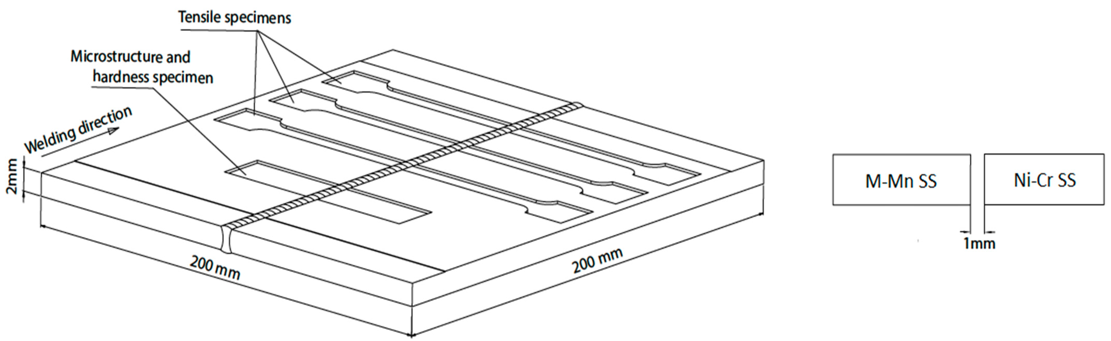
2. Materials and Methods

Low-Ni, medium-Mn austenitic stainless steel, M-Mn SS, and Ni-Cr austenitic stainless steel, Ni-Cr SS, were used for dissimilar butt joints. The base metals were received in the form of 2 mm thick sheets. Filler metal of ER308L was used for the welding experiments. Table 1 shows the chemical compositions of the studied steels and filler metals. The chemical analysis was carried out by utilizing optical emission spectroscopy (FOUNDRY-MASTER Pro, OXFORD INSTRUMENTS, High Wycombe, UK). The edges of the cut specimens were cleaned by a shaper machine via mechanical removal of 0.5 mm from the surfaces of specimens that will be welded. In addition, the surfaces of the specimens were chemically cleaned with ethanol to avoid any greases, oil, or dust on the edges.
Figure 1 shows a schematic illustration of the butt joints with a root gap of 1 mm. The welding process was carried out using the GTAW technique (ESAB Tig 4300i AC/DC) for the root pass and the cup pass. A pure argon shielding gas of purity 99.8% was used for all the welding experiments with 15 L/min. Argon gas was used to protect the root side from oxidation and make welds with high quality at the same flow rate of 15 L/min. No preheat or post-weld heat treatment was applied to the specimens
The welding current is considered as the most influential parameter, which affects the melting rate of the filler metals as well as the mechanical properties of base metals at the HAZ. In addition, it affects the speed and heat input of the welding process. Hence, welding was performed at the current range varying between 50 to 110 A. The heat input was calculated according to Equation (1) as follows:
Heat   input   ( kJ / mm ) = η   ×   I   × V S   × 1000
where η is the arc efficiency for the GTAW process and η equals 0.6 according to BS EN 1011-1 [30]. I is the welding current in ampere (A), V is the arc voltage in volt (V), and S is the welding speed in mm/s.
Table 2 represents the welding parameter of the GTAW process at two levels of different heat inputs, namely, low and high heat inputs.
After the completion of the joining processes, the welded metals were examined by visual methods and radiographic test (RT) to inspect the weld quality of the welded specimens. Figure 1 shows preparations of specimens in perpendicular sections relative to the weld direction to observe microstructure changes after welding processes under low and high heat inputs. The specimens were cut from the welding samples using an electric discharge machine (EDM) (Chmer, Taichung, Taiwan).
The dissimilar butt joints of M-Mn/Ni-Cr SS were transversely cross sectioned and mechanically grounded and polished to prepare metallographic specimens. The specimens were etched via an electrolytic oxalic acid etchant according to the ASTM E407-07 (10 g of oxalic acid and 100 mL distilled water at 6 V for 1 min) [31]. The microstructures of the weldments were investigated by using an optical microscope (Olympus PMG 3, Waltham, MA, USA), which coupled with an image analyzing software. Moreover, scanning electron microscopy (SEM) (QUANTA FEG 250) equipped with energy dispersive spectroscopy (EDS) (FEI, Hillsboro, OR, USA) was used to determine the chemical composition of the weld metals and provide additional high-resolution images of the weld metal. In addition, SEM was used to provide the details of the fractured surfaces after tensile testing in order to examine the mode of fracture. The hardness test was performed according to the Vickers hardness (HV) scale (Matsuzawa) at room temperature. The hardness tester is equipped with a diamond indenter under a load of 10 kg for a penetration holding time of 15 s.
Tensile specimens were cut parallel to the rolling direction of the sheets and perpendicular to the welding pool direction. Three specimens per heat input were machined out from the weld pads by EDM. Dog-bone-shaped specimens were prepared according to the ASTM E8/E8M standard with a gauge length of 50 mm [32]. Uniaxial tensile testing was performed by using a hydraulic universal testing machine (UH-F1000kNI SHIMADZU, Tokyo, Japan) at a quasi-static strain rate of 10−3 s−1 at room temperature.

3. Results and Discussion

3.1. Metallographic Characterization

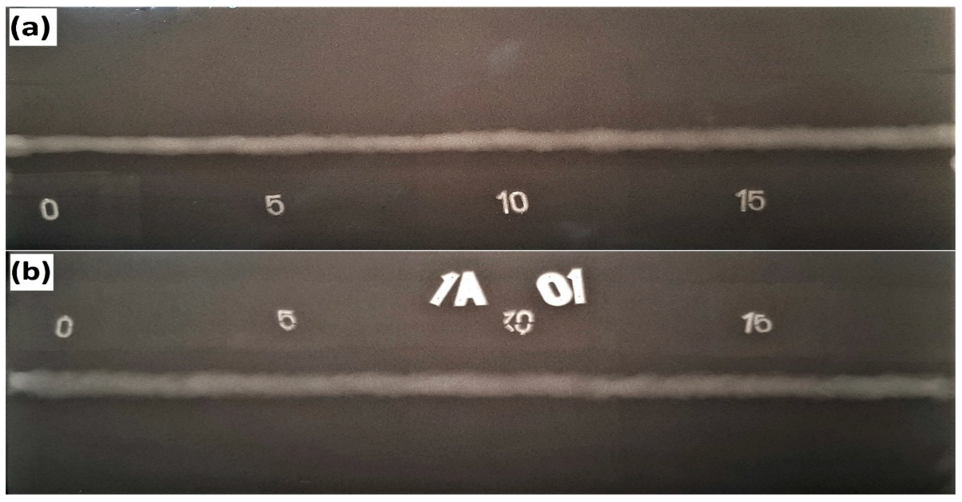
3.1.1. Macrostructure Investigation

Figure 2 shows the radiographic films after dissimilar welding of M-Mn SS and Ni-Cr SS at low and high heat inputs. Clearly, the weldments are sound without weld defects, such as porosity, undercuts, or blowholes, with full penetration. This shows that the welding process parameters applied during the joining of the paired steels are appropriate.
Table 3 illustrates the width of the face and root weld metals of the joints. It is observed that the widths of the face and root weld metals increase with the heat input. Since by increasing the heat input, the produced molten pool size is higher. Consequently, the FZ dimensions increase.

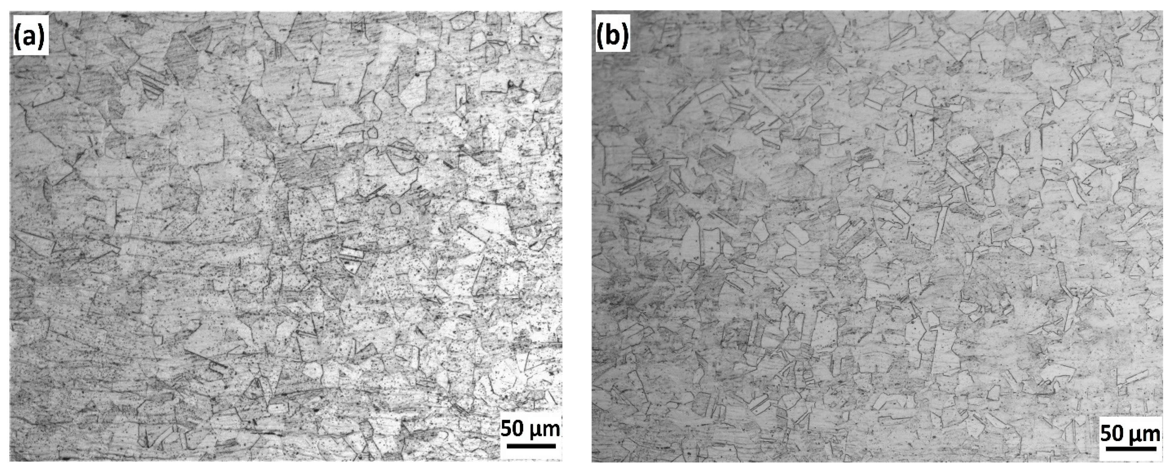
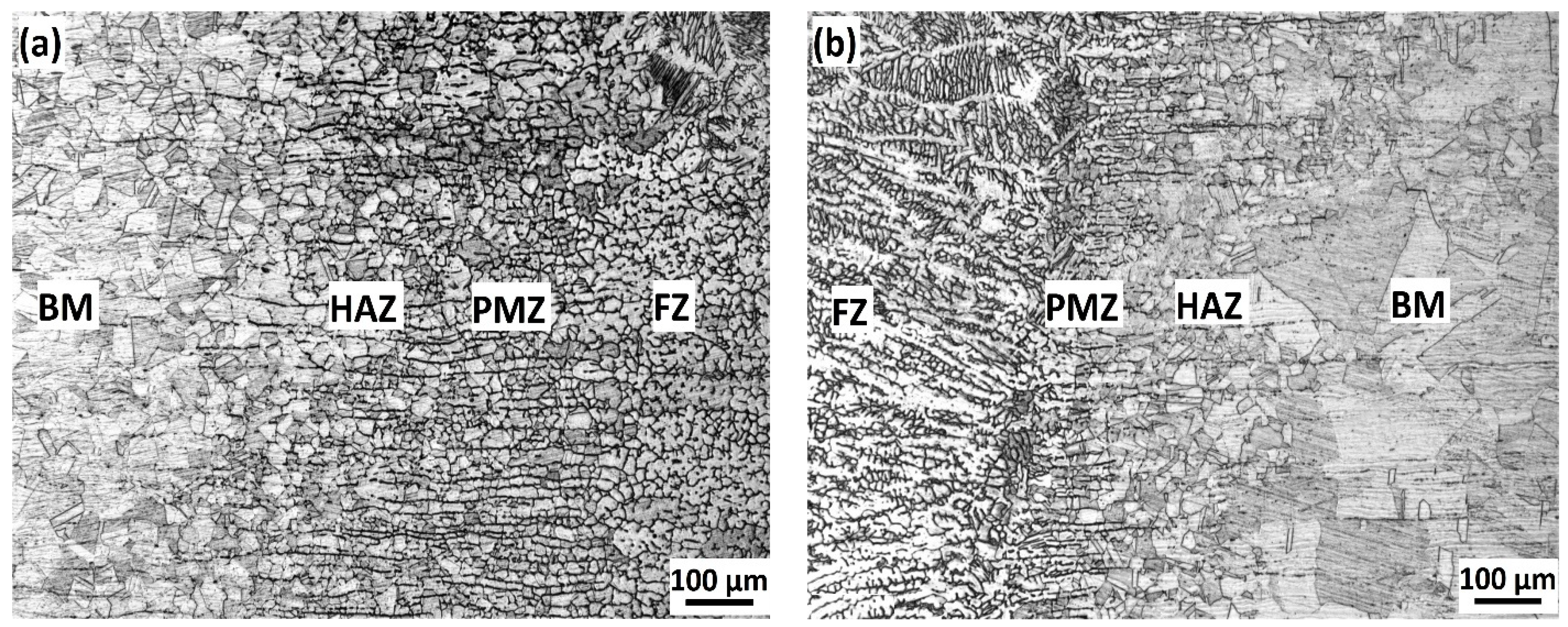
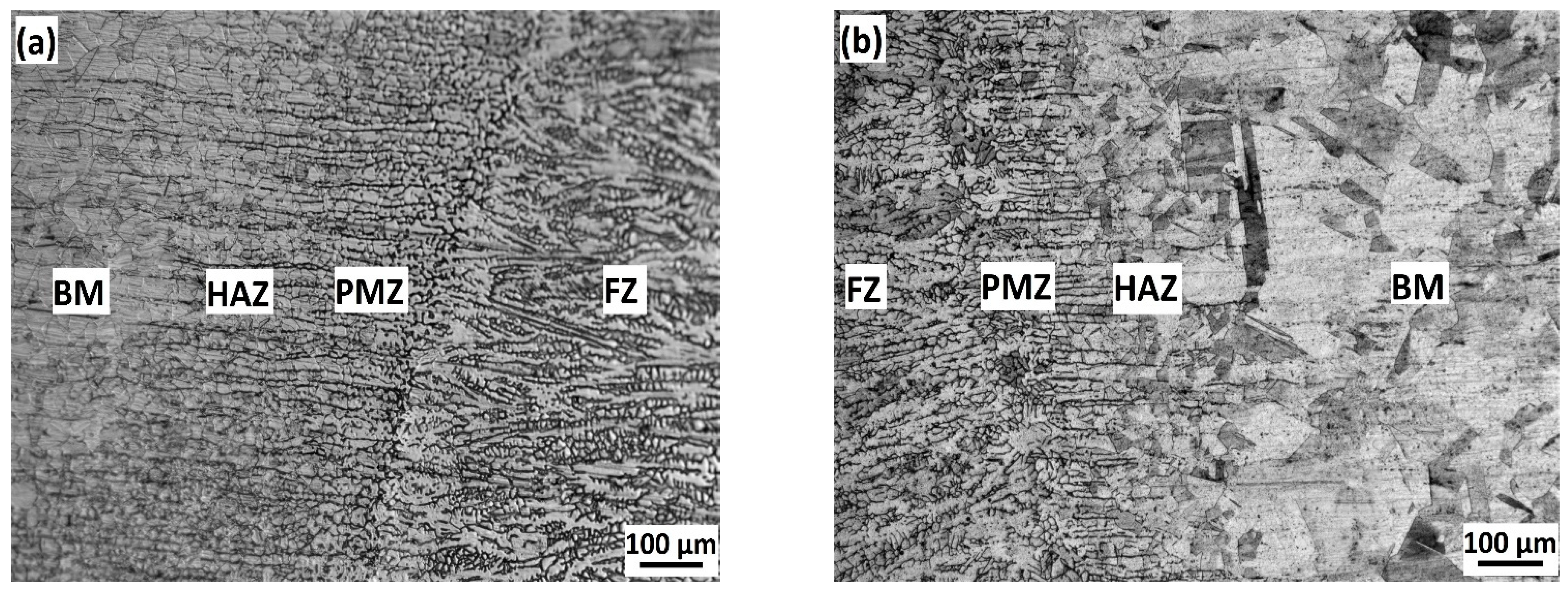
3.1.2. Microstructure of Base and Weld Metals

Figure 3 shows the microstructures of the base metals, M-Mn SS, and Ni-Cr SS, which were observed via optical microscopy. It is observed that the microstructures of the two alloys consist of a fully austenitic structure with annealing twins.
The microstructural characteristics of the FZ welded at low and high heat inputs are shown in Figure 4. It is observed that the FZs of both heat inputs consist of austenitic matrix and delta ferrite phase. Moreover, the volume fraction of delta ferrite was measured by a ferritescope. The recorded ferrite contents of the weldments are 7.8% and 6.2% at low and high heat inputs, respectively. Therefore, we can conclude that the amount of the delta ferrite increases with the decrease in heat input. The increase in the delta ferrite content at low heat input is attributed to the higher cooling rate, which restricted ferrite transformation to austenite. This is in agreement with the work of Kumar and Shahi [27].
Table 3 shows the values of the dendrite length and interdendritic spacing at both heat inputs. Clearly, the dendrite length and interdendritic spacing increased from 109.2 ± 5 µm and 17.1 ± 3 µm at the low heat input to 171.9 ± 6 µm and 28.6 ± 4 µm at the high heat input, respectively. It seems that the high heat input does allow the dendritic structure to enlarge in the weld zone.
Figure 5 and Figure 6 show the optical micrographs of dissimilar welding of M-Mn SS and Ni-Cr SS at low and high heat inputs, respectively. Clearly the optical micrographs of the two heat inputs consist of four regions: FZ, partially melted zone (PMZ), HAZ, and BM, as depicted in Figure 5 and Figure 6. The PMZ appears similar to a layer after the FZ, where the BM has been melted and solidified without mixing with filler metal. The HAZ was significantly influenced by the value of the heat input during the welding process. On the one hand, under low heat input conditions, the width of PMZ and HAZ approximately equals 388 µm and 313 µm for the M-Mn SS side and the Ni-Cr SS side, respectively. On the other hand, under high heat input, the width of PMZ and HAZ approximately equals 432 µm and 373 µm for the M-Mn SS side and the Ni-Cr SS side, respectively.
It is observed that as the heat input increases, the width of PMZ and HAZ increases at the two sides of the weld metal. This is attributed to the low cooling rate associated with the high heat input, allowing sufficient time for grain growth, and hence the size of the PMZ and HAZ was increased. Moreover, the widths of PMZ and HAZ of M-Mn SS side are higher than those of Ni-Cr SS side. This is attributed to the effect of volumetric heat capacities of M-Mn SS lower than Ni-Cr SS and the higher susceptibility of M-Mn SS towards inter granular precipitations, which agrees with the literature [20,24].
Figure 7 shows Cr carbides formation at the grain boundaries of the microstructure of the HAZ at both sides of the weld metal and the FZ adjacent to the weld interface of M-Mn SS and Ni-Cr SS at the high heat input. It is observed that the Cr carbides formation increased at the HAZ of M-Mn side and the FZ adjacent to the weld interface of M-Mn compared to HAZ of Ni-Cr side and the FZ adjacent to the weld interface of Ni-Cr. Moreover, the dark particles have a high content of Cr, while the white regions have a low content of Cr as examined by the EDS affiliated with the SEM. This is attributed to the diffusion of C atoms from the base metals to the weld zone forming Cr carbides adjacent to the weld interface of both sides, which was concluded by the research conducted by Vashishtha et al. [33], Chuaiphan et al. [28,34], and Kumar et al. [27].

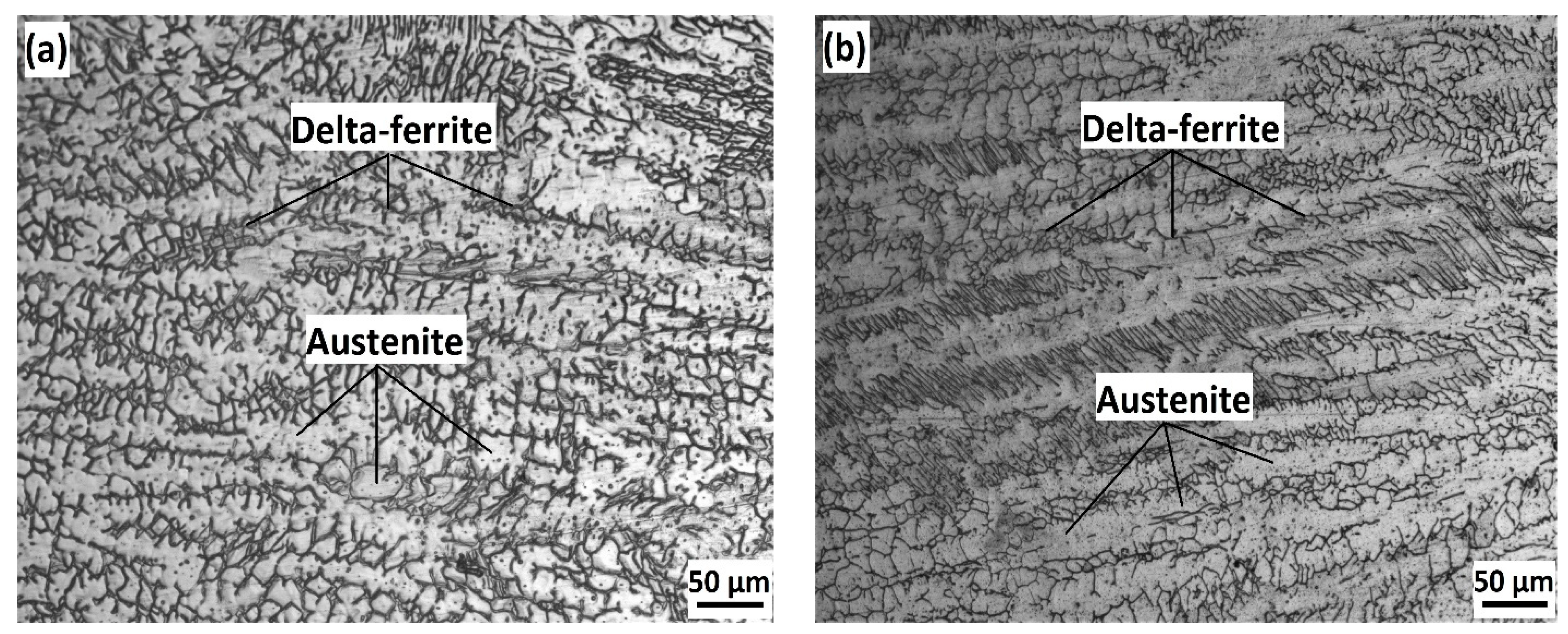
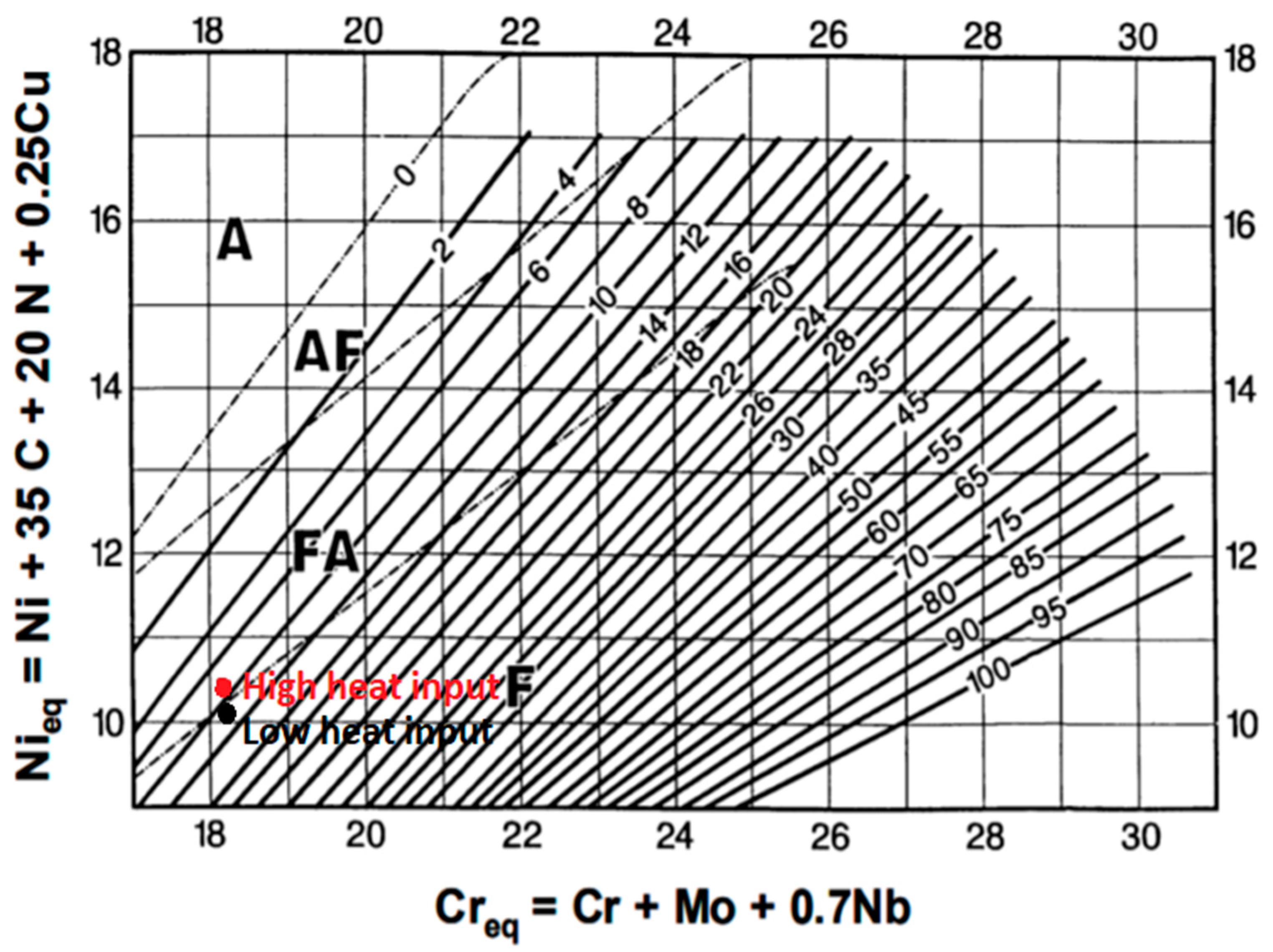
3.1.3. Solidification Mode and Delta-Ferrite Content

In the present work, we employed the WRC-1992 Constitution Diagram for Stainless Steel Weld Metals to estimate the predicted ferrite content related to the values of the chromium equivalent (Creq) and nickel equivalent (Nieq) of the weld zone [35,36]. The chemical compositions of the FZs were determined by EDS to calculate Creq and Nieq according to the Equations (2) and (3), as follows.
Creq = Cr + Mo + 0.5 Nb + 1.5 Si
Nieq = Ni + 30 (C + N) + 0.5 (Mn + Cu)
However, EDS is not accurate for low atomic number elements, such as C and N, since the sensitivity of EDS analysis is approximately 0.1 wt.% for all elements, i.e., higher C content of the paired steels and the filler metal [37]. The C contents of the FZs were calculated by stoichiometry method, which estimates the quantitative relationship between the C contents of the paired steel sheets (M-Mn SS and Ni-Cr SS) and the filler metal (ER308L) and the dilution percent of each steel in the joint according to the Equation (4):
C FZ = ( C . D ) Mn   SS + ( C . D ) NiCr   SS + ( C . D ) FM
where C FZ is the C content of the FZ, ( C . D ) Mn   SS denotes the C content and dilution percent of M-Mn SS, ( C . D ) NiCr   SS denotes C content and dilution percent of Ni-Cr SS, and ( C . D ) FM denotes C content and dilution percent of the filler metal. Based on the measured delta ferrite content, the dilution precents of the paired steels were taken as D = 15% and D = 70% for the filler metal. Consequently, the C content of the FZ is 0.032 wt.% at the low heat input. Similarly, the C content of the FZ was calculated to be 0.037 wt.% at the high heat input.
Table 4 shows the EDS elemental analysis of the FZs at low and high heat input. The corresponding Creq, Nieq, and the predicted content of the delta ferrite are shown in Table 4. For comparison, the actual delta ferrite was measured by a ferrite scope. It is now well established that there are different solidification modes of ASSs during welding based on the ratio of Creq/ Nieq, as shown below [38]:
  • Austenitic (A) mode: L Metals 11 01439 i001 (L + γ) Metals 11 01439 i001 γ,
    (Creq/Nieq) < 1.25;
  • Austenitic Ferritic (AF) mode: L Metals 11 01439 i001 (L + γ) Metals 11 01439 i001 (L + γ + δ) Metals 11 01439 i001 (γ + δ),
    1.25 < (Creq/Nieq) < 1.48;
  • Ferritic austenitic (FA) mode: L Metals 11 01439 i001 (L + δ) Metals 11 01439 i001 (L + δ + γ) Metals 11 01439 i001 (γ + δ),
    1.48 < (Creq/Nieq) < 1.95;
  • Ferritic (F) mode: L Metals 11 01439 i001 (L + δ) Metals 11 01439 i001 δ Metals 11 01439 i001 (γ + δ),
    (Creq/Nieq) >1.95.
In the present instance, the Creq/Nieq values seem to result in inducing delta ferrite within the austenitic matrix, as indicated by locating the Creq/Nieq values of the two heat inputs on the WRC diagram in Figure 8. It is observed that the predicted and the measured contents of the delta ferrite content are comparative since that the predicted delta ferrite content by the WRC diagram are approximately equal 8.5% and 7% at low and high heat inputs, respectively. As mentioned previously, the ferritescope measurements showed that the contents of delta ferrite phase in the FZ are 7.8% and 6.2% at low and high heat input, respectively.

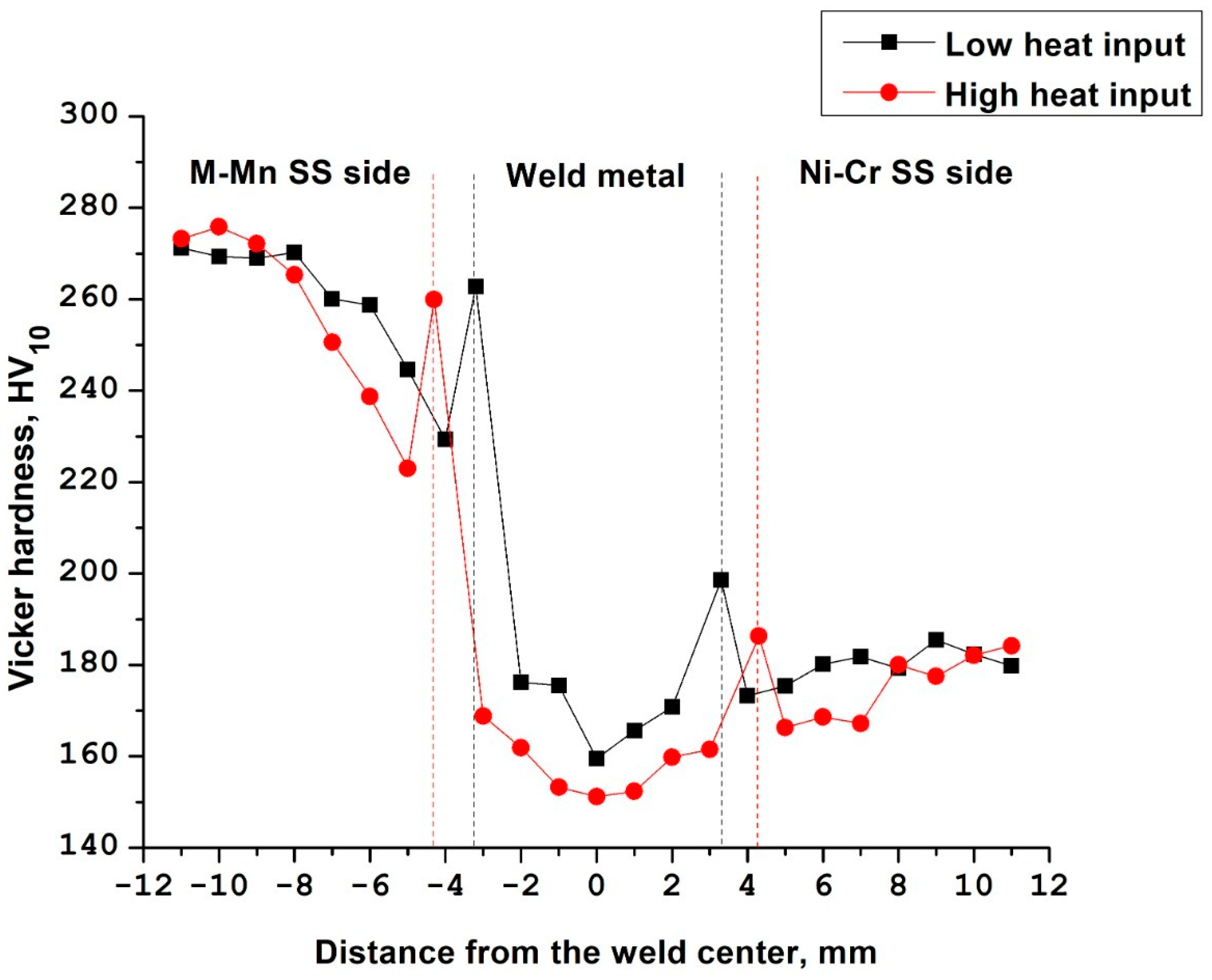
3.2. Hardness Results

Figure 9 shows graphical representations of the hardness measurement results along the BM, HAZ, PMZ, and FZ at both low and high heat inputs. The average hardness values of the M-Mn SS and Ni-Cr SS (BMs) are 268.9 ± 7 HV and 181.3 ± 4 HV, respectively.
On one hand, under low heat input condition, the hardness values recorded 159.5 HV in the FZ. In addition, the hardness values recorded 262.8 HV and 198.6 HV in the PMZ of the M-Mn SS side and the Ni-Cr SS side, respectively. On the other hand, under high heat input, the hardness values recorded 151.2 HV in the FZ, while it recorded 259.9 HV and 186.3 VH in the PMZ of the M-Mn SS side and the Ni-Cr SS side, respectively.
Furthermore, under low heat input condition, the hardness values recorded 229.3 and 173.2 HV in the HAZ of the M-Mn SS side and Ni-Cr SS side, respectively. Moreover, under high heat input, the hardness values recorded 223 and 166.3 HV in the HAZ of the M-Mn SS side and the Ni-Cr SS side, respectively.
Clearly, the welded metals have lower hardness values than the base metals. Moreover, the welded metal under high heat input has lower hardness values than welded metal under low heat input. These decreases in the hardness values are attributed to the pre-formed delta ferrite present in the weld metal and/or the effect of chromium precipitation formed during the solidification stage in this zone, which agrees with the literature [39].
The PMZ exhibited higher hardness records than the weld metal and HAZ at low and high heat inputs due to the fact of partially unmelted grains at the fusion boundary zone as well as the effect of chromium precipitation formed during the solidification stage in the FZ. The hardness values of HAZs for both sides at low and high heat inputs near the PMZ are lower than the HAZs near the base metals due to the slower cooling rate and grain coarsening presence in the adjacent HAZ to the PMZ. Kumar et al. [27] and Bansod et al. [39] reported similar trends for microhardness values during the investigation of GTAW welded 304 SS and SMAW welded low nickel SS to 304 SS, respectively, at different heat inputs.

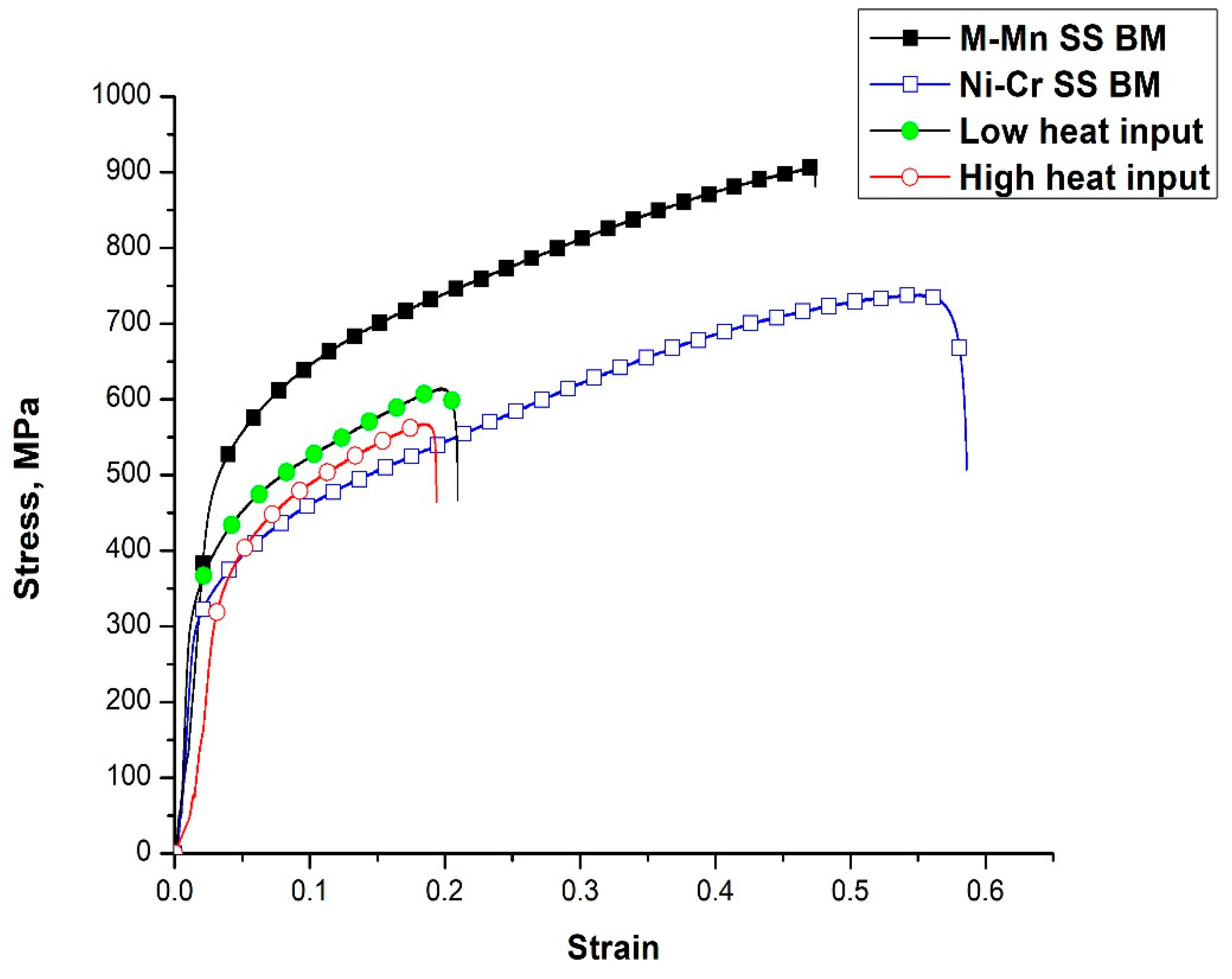
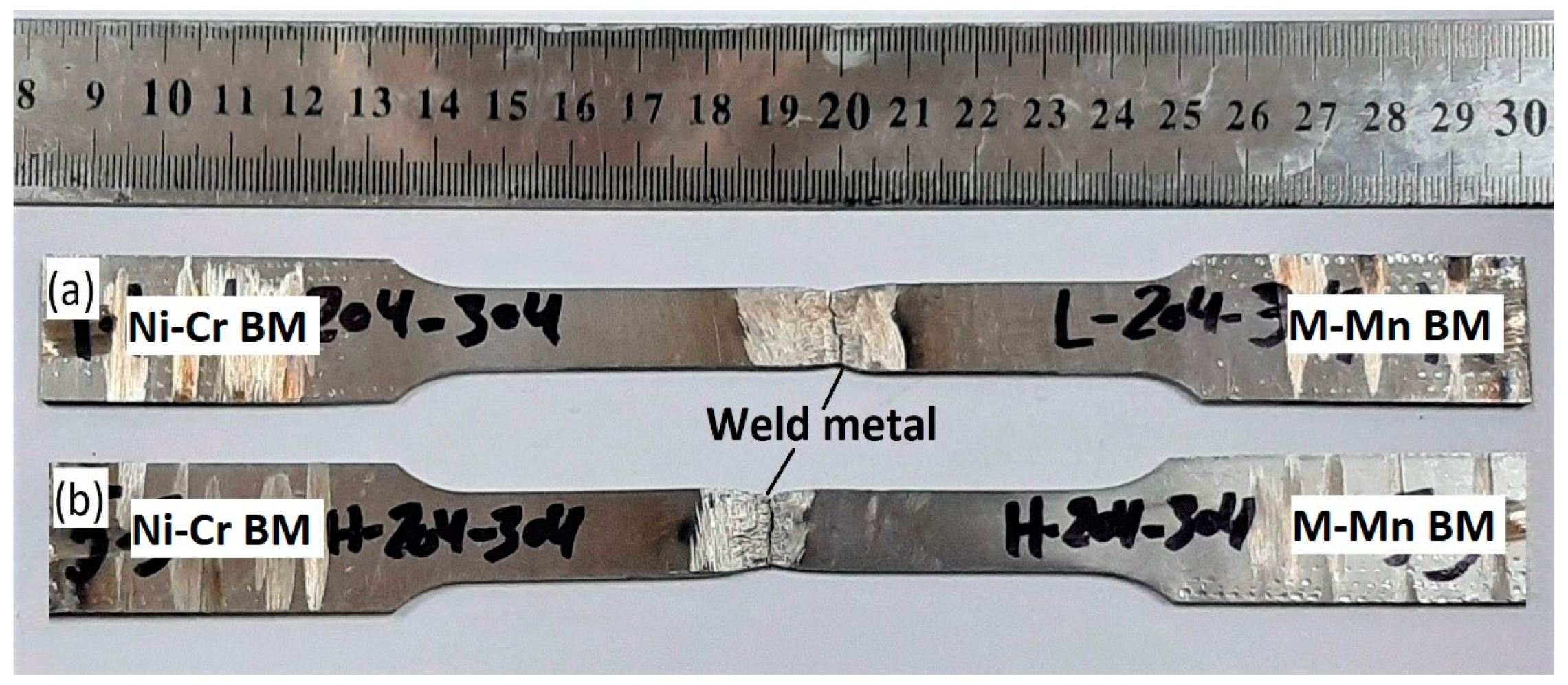
3.3. Tension Test Results
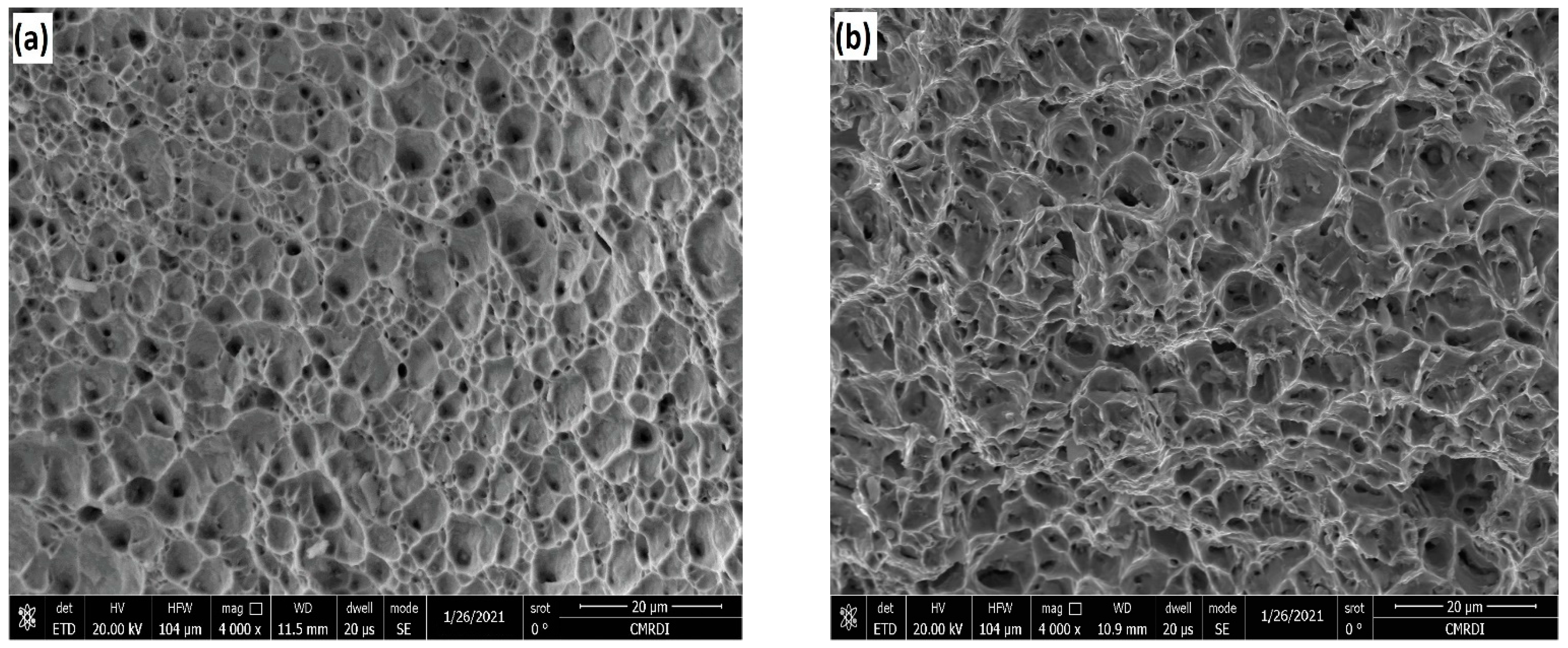
Figure 10 displays the tensile behavior of the base metals and dissimilar welding of M-Mn SS and Ni-Cr SS at low and high heat inputs. It is observed that the ultimate tensile strength increases with the decrease in heat input for dissimilar welding. Moreover, the elongation percentage increases with the decrease in heat input. These results can be attributed to the high content of delta ferrite in the weld metal at the low heat input. In addition, the small dendrite sizes and interdendritic spacing in the weld metal enhance the tensile properties [13,27]. The joint efficiency was calculated according to Equation (5) [40,41] and presented in Table 5. Furthermore, the fracture of welded tensile specimens happened at the weld metal because the filler metal has an ultimate tensile strength lower than the base metals, as shown in Figure 11.
Joint   efficiency = Ultimate   tensile   strength   of   the   weld   metal Ultimate   tensile   strength   of   the   soft   base   metal × 100
Table 5 listed the tensile mechanical properties of the dissimilar joints comparing with those of the BMs. It is observed that the dissimilar joints exhibit lower strengths with a joint efficiency of ~80% since the quasi-static mechanical properties of the joints are characterized by a low ductility of ~20% and low strengths of ~(580–610 MPa). The dissimilar joint welded with the low heat input exhibited higher tensile strength. This could be explained by the fact that by increasing the heat input, the cooling rate decreases. As a result, a softer grain structure is formed. Consequently, the mechanical strength decreases. Furthermore, the fast cooling rate associated with the low heat input results in higher delta ferrite content promoted in the FZ. This also enhances the strength of the joint welded at low heat input, which is in agreement with the literature [13,33,38].

3.4. Fractography

The fracture surface morphology of the dissimilar joints that underwent tensile testing was examined by using SEM to reveal the fracture mechanism. Figure 12 shows the fractography of tensile specimens of dissimilar M-Mn SS and Ni-Cr SS welded joints at low and high heat inputs. It is observed that the fracture surfaces of both joints welded at low and high heat inputs exhibit a dimpled feature, which is a typical characteristic feature of the ductile fracture. Interestingly, the fracture surface of the joints welded with low heat input contains small dimples of various sizes. This indicates that a higher ductility of the joint could be achieved. In contrast, coarse and elongated dimples are promoted in the fracture surface of the joints welded with high heat input. This reveals grain coarsening in the structure of the FZ. Hence, the mechanical strength of the joint decreases. This matches with the tensile curves of the weldments with different heat inputs, as shown in Figure 10.

4. Conclusions

Dissimilar welding of M-Mn SS to Ni-Cr SS was performed by the GTAW technique at low and high heat inputs (0.486 kJ/mm and 0.558 kJ/mm). There were no defects such as porosity, undercuts, or cracks at the weld metals, and full penetration of the welding path was obtained for dissimilar welding at low and high heat inputs. The following conclusions were drawn from the current investigation:
  • The weld metals were solidified in FA mode with conformable delta ferrite content (3–10) vol.% to avoid solidification cracks. Moreover, the delta ferrite content increased with the decrease in the heat input.
  • The microstructure of weld metals consists of a duplex structure containing austenite matrix and delta ferrite for both heat inputs. Moreover, the dendrite length and interdendritic spacing increased with the increase in heat input.
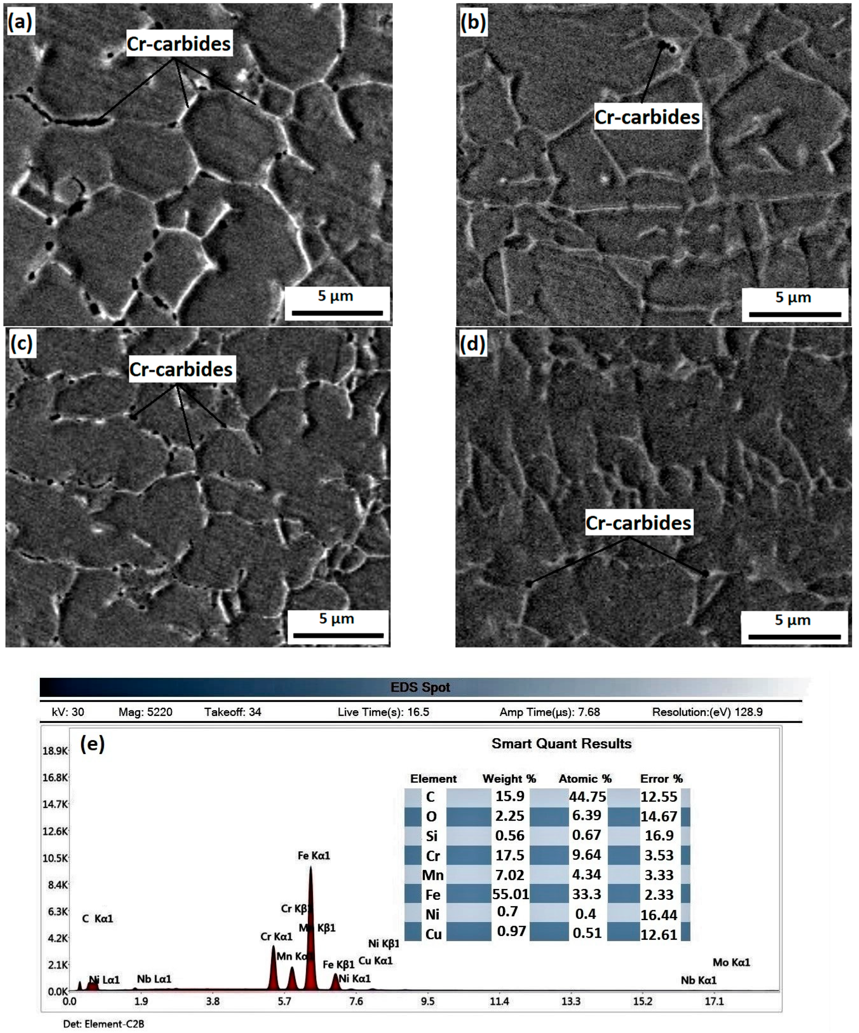
  • Cr carbides were precipitated at the grain boundaries in the HAZ and FZ at the high heat input due to the diffusion of the C atoms from the lower Cr base metals to the higher Cr weld metal.
  • The weld metals have hardness values that are lower than the base metals under the two different heat inputs. Moreover, the hardness value of weld metals decreased with the increase in heat input.
  • At low heat inputs, the ultimate tensile strength and elongation percentage were higher than those of the high heat input conditions. However, fractures occurred in the weld metal under the two heat inputs in a ductile mode.
Based on the present investigation, it is recommended to perform dissimilar welding of M-Mn SS and Ni-Cr SS using the GTAW technique at low heat inputs (0.486 kJ/mm) because the tensile strength and ductility are higher than the high heat input conditions.

Author Contributions

Investigation, Writing—Original Draft, I.R.I.; Supervision, Visualization, Writing—Review & Editing, M.K.; Investigation, H.A.A.-A.; Supervision, T.S.M.; Supervision, Conceptualization, Writing-Review & Editing, A.H. All authors have read and agreed to the published version of the manuscript.

Funding

This research received no external funding.

Institutional Review Board Statement

Not applicable.

Informed Consent Statement

Not applicable.

Data Availability Statement

All the data generated during this study are included in this article.

Conflicts of Interest

The authors declare no conflict of interest.

References

  1. George, G.; Shaikh, H. 1-Introduction to Austenitic Stainless Steels. In Corrosion of Austenitic Stainless Steels; Khatak, H.S., Raj, B., Eds.; Woodhead Publishing: Oxford, UK, 2002; pp. 1–36. [Google Scholar]
  2. Singh, R. 7-Welding, Corrosion-Resistant Alloys—Stainless Steel. In Applied Welding Engineering, 3rd ed.; Singh, R., Ed.; Butterworth-Heinemann: Oxford, UK, 2020; pp. 251–271. [Google Scholar]
  3. Singh, R. 8-Stainless Steels and Other CRAs. In Applied Welding Engineering, 3rd ed.; Singh, R., Ed.; Butterworth-Heinemann: Oxford, UK, 2020; pp. 77–84. [Google Scholar]
  4. New200-Series Stainless Steel: An Opportunity or a Threat to Theimage of Stainless Steel; International Stainless Steel Forum (ISSF): Brussels, Belgium, 2005.
  5. Fu, Y.; Wu, X.; Han, E.-H.; Ke, W.; Yang, K.; Jiang, Z. Effects of nitrogen on the passivation of nickel-free high nitrogen and manganese stainless steels in acidic chloride solutions. Electrochim. Acta 2009, 54, 4005–4014. [Google Scholar] [CrossRef]
  6. Charles, J.; Mithieux, J.-D.; Krautschick, J.; Suutala, N.; Simón, J.A.; Van Hecke, B.; Pauly, T. A new European 200 series standard to substitute 304 austenitics. Revue Métallurgie 2009, 106, 90–98. [Google Scholar] [CrossRef]
  7. Mudali, U.K.; Pujar, M.G. 3-Pitting Corrosion of Austenitic Stainless Steels and Their Weldments. In Corrosion of Austenitic Stainless Steels; Khatak, H.S., Raj, B., Eds.; Woodhead Publishing: Cambridge, UK, 2002; pp. 74–105. [Google Scholar]
  8. Khobragade, N.N.; Khan, M.I.; Patil, A.P. Corrosion Behaviour of Chrome–Manganese Austenitic Stainless Steels and AISI 304 Stainless Steel in Chloride Environment. Trans. Indian Inst. Met. 2013, 67, 263–273. [Google Scholar] [CrossRef]
  9. Dak, G.; Pandey, C. A critical review on dissimilar welds joint between martensitic and austenitic steel for power plant application. J. Manuf. Process. 2020, 58, 377–406. [Google Scholar] [CrossRef]
  10. Sabzi, M.; Dezfuli, S.M. Drastic improvement in mechanical properties and weldability of 316L stainless steel weld joints by using electromagnetic vibration during GTAW process. J. Manuf. Process. 2018, 33, 74–85. [Google Scholar] [CrossRef]
  11. Xie, W.; Yang, C. Microstructure, mechanical properties and corrosion behavior of austenitic stainless steel sheet joints welded by gas tungsten arc (GTA) and ultrasonic–wave–assisted gas tungsten pulsed arc (U–GTPA). Arch. Civ. Mech. Eng. 2020, 20, 1–14. [Google Scholar] [CrossRef] [Green Version]
  12. Kumar, S.M.; Sankarapandian, S.; Shanmugam, N.S. Investigations on mechanical properties and microstructural examination of activated TIG-welded nuclear grade stainless steel. J. Braz. Soc. Mech. Sci. Eng. 2020, 42, 1–21. [Google Scholar] [CrossRef]
  13. Tandon, V.; Thombre, M.A.; Patil, A.P.; Taiwade, R.V.; Vashishtha, H. Effect of Heat Input on the Microstructural, Mechanical, and Corrosion Properties of Dissimilar Weldment of Conventional Austenitic Stainless Steel and Low-Nickel Stainless Steel. Met. Microstruct. Anal. 2020, 9, 668–677. [Google Scholar] [CrossRef]
  14. Lin, Y.; Chen, P. Effect of nitrogen content and retained ferrite on the residual stress in austenitic stainless steel weldments. Mater. Sci. Eng. A 2001, 307, 165–171. [Google Scholar] [CrossRef]
  15. Chuaiphan, W.; Srijaroenpramong, L. Optimization of gas tungsten arc welding parameters for the dissimilar welding between AISI 304 and AISI 201 stainless steels. Def. Technol. 2019, 15, 170–178. [Google Scholar] [CrossRef]
  16. Lu, B.; Chen, Z.; Luo, J.; Patchett, B.; Xu, Z. Pitting and stress corrosion cracking behavior in welded austenitic stainless steel. Electrochimica Acta 2005, 50, 1391–1403. [Google Scholar] [CrossRef]
  17. Kulkarni, A.; Dwivedi, D.; Vasudevan, M. Dissimilar metal welding of P91 steel-AISI 316L SS with Incoloy 800 and Inconel 600 interlayers by using activated TIG welding process and its effect on the microstructure and mechanical properties. J. Mater. Process. Technol. 2019, 274, 116280. [Google Scholar] [CrossRef]
  18. Bansod, A.V.; Patil, A.P.; Verma, J.; Shukla, S. Microstructure, Mechanical and Electrochemical Evaluation of Dissimilar low Ni SS and 304 SS using Different Filler Materials. Mater. Res. 2019, 22, 22. [Google Scholar] [CrossRef] [Green Version]
  19. Rahul Kumar Keshari, P.L.S. Mechanical characterization of dissimilar welded joint of SS202 and SS304 by tungsten inert gas welding. Int. J. Res. Eng. Innov. 2019, 3, 245–252. [Google Scholar]
  20. Chuaiphan, W.; Srijaroenpramong, L. Evaluation of microstructure, mechanical properties and pitting corrosion in dissimilar of alternative low cost stainless steel grade 204Cu and 304 by GTA welding joint. J. Mater. Res. Technol. 2020, 9, 5174–5183. [Google Scholar] [CrossRef]
  21. Pantelis, D.I.; Tsiourva, T.E. 10-Corrosion of Weldments. In Trends in Oil and Gas Corrosion Research and Technologies; El-Sherik, A.M., Ed.; Woodhead Publishing: Boston, FL, USA, 2017; pp. 249–270. [Google Scholar]
  22. Mirshekari, G.; Tavakoli, E.; Atapour, M.; Sadeghian, B. Microstructure and corrosion behavior of multipass gas tungsten arc welded 304L stainless steel. Mater. Des. 2014, 55, 905–911. [Google Scholar] [CrossRef]
  23. Bansod, A.V.; Patil, A.P. Effect of Welding Processes on Microstructure, Mechanical Properties, and Corrosion Behavior of Low-Nickel Austenitic Stainless Steels. Met. Microstruct. Anal. 2017, 6, 304–314. [Google Scholar] [CrossRef]
  24. Vashishtha, H.; Taiwade, R.V.; Sharma, S.; Patil, A.P. Effect of welding processes on microstructural and mechanical properties of dissimilar weldments between conventional austenitic and high nitrogen austenitic stainless steels. J. Manuf. Process. 2017, 25, 49–59. [Google Scholar] [CrossRef]
  25. Chandra-Ambhorn, S.; Chauiphan, W.; Sukwattana, N.C.; Pudkhunthod, N.; Komkham, S. Plasma Arc Welding between AISI 304 and AISI 201 Stainless Steels Using a Technique of Mixing Nitrogen in Shielding Gas. Adv. Mater. Res. 2012, 538–541, 1464–1468. [Google Scholar] [CrossRef]
  26. Durgutlu, A. Experimental investigation of the effect of hydrogen in argon as a shielding gas on TIG welding of austenitic stainless steel. Mater. Des. 2004, 25, 19–23. [Google Scholar] [CrossRef]
  27. Kumar, S.; Shahi, A. Effect of heat input on the microstructure and mechanical properties of gas tungsten arc welded AISI 304 stainless steel joints. Mater. Des. 2011, 32, 3617–3623. [Google Scholar] [CrossRef]
  28. Chuaiphan, W.; Srijaroenpramong, L. Effect of welding speed on microstructures, mechanical properties and corrosion behavior of GTA-welded AISI 201 stainless steel sheets. J. Mater. Process. Technol. 2014, 214, 402–408. [Google Scholar] [CrossRef]
  29. Taiwade, R.V.; Patil, A.P.; Ghugal, R.D.; Patre, S.J.; Dayal, R.K. Effect of Welding Passes on Heat Affected Zone and Tensile Properties of AISI 304 Stainless Steel and Chrome-Manganese Austenitic Stainless Steel. ISIJ Int. 2013, 53, 102–109. [Google Scholar] [CrossRef] [Green Version]
  30. Weman, K. Introduction to welding. In Welding Processes Handbook; Elsevier: Amsterdam, The Netherlands, 2012; pp. 1–12. [Google Scholar]
  31. ASTM E407-07. Standard Practice for Microetching Metals and Alloys; ASTM International: West Conshohocken, PA, USA, 2015. [Google Scholar]
  32. ASTM E8/E8M. Standard Test Methods for Tension Testing of Metallic Materials; ASTM International: West Conshohocken, PA, USA, 2021. [Google Scholar]
  33. Vashishtha, H.; Taiwade, R.V.; Sharma, S.; Marodkar, A.S. Microstructural and Mechanical Properties Evolution of Bimetallic Cr-Ni and Cr-Mn-Ni Stainless Steel Joints. Met. Microstruct. Anal. 2019, 8, 359–369. [Google Scholar] [CrossRef]
  34. Chuaiphan, W.; Srijaroenpramong, L. Optimization of TIG welding parameter in dissimilar joints of low nickel stainless steel AISI 205 and AISI 216. J. Manuf. Process. 2020, 58, 163–178. [Google Scholar] [CrossRef]
  35. A new constitution diagram for predicting ferrite content of stainless steel weld metals. Mater. Des. 1993, 14, 345–348. [CrossRef]
  36. Kotecki, D.; Siewert, T. WRC-1992 Constitution Diagram for Stainless Steel Weld Metals. Weld. J. 1992, 71, 174. [Google Scholar]
  37. Gharehbaghi, A. Precipitation Study in a High Temperature Austenitic Stainless Steel Using Low Voltage Energy Dispersive X-ray Spectroscopy. Master’s Thesis, Royal Institute of Technology (KTH), Stockholm, Sweden, 28 March 2012. [Google Scholar]
  38. Vashishtha, H.; Taiwade, R.; Khatirkar, R.; Dhoble, A. Effect of austenitic fillers on microstructural and mechanical properties of ultra-low nickel austenitic stainless steel. Sci. Technol. Weld. Join. 2016, 21, 331–337. [Google Scholar] [CrossRef]
  39. Bansod, A.V.; Patil, A.P.; Moon, A.; Shukla, S. Microstructural and Electrochemical Evaluation of Fusion Welded Low-Nickel and 304 SS at Different Heat Input. J. Mater. Eng. Perform. 2017, 26, 5847–5863. [Google Scholar] [CrossRef]
  40. Kim, S.-Y.; Jung, S.-B.; Shur, C.-C.; Yeon, Y.-M.; Kim, D.-U. Mechanical properties of copper to titanium joined by friction welding. J. Mater. Sci. 2003, 38, 1281–1287. [Google Scholar] [CrossRef]
  41. Khidhir, G.I.; Baban, S.A. Efficiency of dissimilar friction welded 1045 medium carbon steel and 316L austenitic stainless steel joints. J. Mater. Res. Technol. 2019, 8, 1926–1932. [Google Scholar] [CrossRef]
Figure 1. Schematic illustration of the specimen sampling from the weld pads.
Metals 11 01439 g001
Figure 2. Radiographic films of weld metal as follows: (a) at low heat input; (b) at high heat input.
Metals 11 01439 g002
Figure 3. Microstructure of base metals: (a) M-Mn SS; (b) Ni-Cr SS.
Metals 11 01439 g003
Figure 4. Microstructure of weld metals showing austenitic matrix and delta ferrite: (a) at low heat input; (b) at high heat input.
Metals 11 01439 g004
Figure 5. Microstructure of dissimilar welding showing BM, HAZ, PMZ, and FZ at the low heat input: (a) M-Mn SS side; (b) Ni-Cr SS side.
Metals 11 01439 g005
Figure 6. Microstructure of dissimilar welding showing BM, HAZ, PMZ, and FZ at the high heat input: (a) M-Mn SS side; (b) Ni-Cr SS side.
Metals 11 01439 g006
Figure 7. SEM micrographs of the microstructures of different regions of the weldment at high heat input: (a) HAZ at the side of the M-Mn; (b) HAZ at the side of Ni-Cr; (c) weld interface of M-Mn; (d) weld interface of Ni-Cr; and (e) EDX analysis of the particles shown in (a).
Metals 11 01439 g007
Figure 8. WRC-1992 diagram for depicting solidification mode and possible range of delta-ferrite content in the weld metals produced at low and high heat inputs [36].
Metals 11 01439 g008
Figure 9. Hardness profile showing hardness of the weld metals and both sides at low and high heat inputs.
Metals 11 01439 g009
Figure 10. Stress–strain curves of base metals and weld metals at low and high heat inputs.
Metals 11 01439 g010
Figure 11. Photograph of the tensile specimens showing the location of fracture in the weld metals: (a) at low heat input; (b) at high heat input.
Metals 11 01439 g011
Figure 12. SEM fractography of the tensile specimen of dissimilar M-Mn SS-Ni-Cr SS welded joints: (a) at low heat input; (b) at high heat input.
Metals 11 01439 g012
Table 1. Chemical composition (wt.%) of the base and filler metals used.
SteelSteel CodeElements (Weight %)
CSiMnCrNiMoCuVNNbFe
low-Ni, medium-Mn austenitic stainless steelM-Mn SS0.0980.159.5714.601.260.0311.430.060.200.043Balance
Ni-Cr austenitic stainless steelNi-Cr SS0.0250.421.1218.707.800.0010.0140.120.100.051Balance
Filler MetalER308L0.020.401.9019.809.800.200.15---Balance
Table 2. GTAW process parameters for dissimilar welding of M-Mn SS and Ni-Cr SS.
SpecimenWelding Parameters
PassCurrent
(A)
Voltage
(V)
Welding Speed
(mm/s)
Heat Input per Pass
(kJ/mm)
Total Heat Input
(kJ/mm)
M-Mn SS-Ni-Cr SS
(Low heat input)
Root7012.52.60.2020.486
Cup11012.52.90.284
M-Mn SS-Ni-Cr SS (High heat input)Root5012.51.60.2340.558
Cup9512.52.20.324
Table 3. Weld dimensions of the weldments at low and high heat inputs.
SpecimenWidth of Face Weld
(mm)
Width of Root Weld
(mm)
Dendrite Length
(µm)
Interdendritic Spacing
(µm)
Low heat input6.55.3109.217.1
High heat input8.66.8171.928.6
Table 4. Chemical composition, Creq/Nieq, and delta-ferrite content of the weld metals.
SpecimenChemical Composition (wt.%)Creq/ NieqDelta Ferrite Content
CrNiMoCuNbCCreqNieqCreq/ NieqPredictedMeasured
Low heat input17.686.220.080.480.060.03218.39.971.848.57.8
High heat input17.596.280.070.470.060.03718.210.181.7976.2
Table 5. Tensile properties of base metals and weld metals.
MaterialsHeat InputTensile PropertiesLocation of Fracture
Yield
(MPa)
Ultimate
(MPa)
Elongation
(%)
Joint
Efficiency (%)
M-Mn SS-BM-480 ± 5915 ± 1047.4-Gauge length
Ni-Cr SS-BM-300 ± 5738 ± 1058.6-Gauge length
M-Mn SS-Ni-Cr SSLow340 ± 10610 ± 102182.7Weld metal
High320 ± 10580 ± 1519.478.6Weld metal
Publisher’s Note: MDPI stays neutral with regard to jurisdictional claims in published maps and institutional affiliations.

