Article

Effect of Micro-Shot Peening on the Fatigue Performance of AISI 304 Stainless Steel

1
Department of Optoelectronics and Materials Technology, National Taiwan Ocean University, Keelung 20224, Taiwan
2
Nuclear Fuels and Materials Division, Institute of Nuclear Energy Research, Taoyuan 32546, Taiwan
3
Center of Excellence for Ocean Engineering, National Taiwan Ocean University, Keelung 20224, Taiwan
*
Author to whom correspondence should be addressed.
Metals 2021, 11(9), 1408; https://doi.org/10.3390/met11091408
Submission received: 5 August 2021 / Revised: 31 August 2021 / Accepted: 1 September 2021 / Published: 6 September 2021
(This article belongs to the Special Issue Surface Modification of Metallic Materials for Wear and Fatigue)

Abstract

:
The effects of micro-shot peening on the rotating bending fatigue resistance of AISI 304 stainless steel (SS) were investigated in this study. The strain-hardening, surface roughness and induced residual stress were inspected and correlated with fatigue strength. Micro-shot peening caused intense strain-hardening, phase transformation and residual stress but was also accompanied by a minor increase in surface roughness. A nanograined structure, which was advantageous to fatigue resistance, was observed in the severe shot-peened layer. The absence of microcracks, minor increase in surface roughness, nanograined structure and induced high compressive residual stress in the shot-peened layer were responsible for the improved fatigue strength of AISI 304 SS.

1. Introduction

Material fatigue is the main cause of the failure in various components or structures [1]. Surface microcrack results in the fatigue initiation, propagation and coalescence of cracks during cyclic loading. In most cases, fatigue cracks are likely to initiate at the inclusion or slip band at the surface. The fatigue properties of a component are affected by factors such as the material microstructure, surface hardness and distribution of residual stress. The introduction of short notch on the surface causes a decrease in fatigue strength/life of 304 SS [2]. The increase in surface hardness and the induced compressive residual stress by surface mechanical treatments are well known to improve both fatigue life and rates of crack initiation [1,3]. Among the various surface modification processes, air blast shot-peening is the easiest to apply to increase the fatigue life of the materials [4,5,6]. In general, the surface of a component is shot with accelerated metal, glass, or ceramic balls to create a plastically deformed layer [4,5,6,7]. However, excessive plastic deformation or formation of surface microcracks by shot-peening will shorten the fatigue life or reduce the fatigue strength [8,9,10]. Moreover, the rough surface that results from shot-peening will damage the appearance of the component or make surface-finishing treatments more difficult to apply. Full peening coverage gives rise to the best fatigue behavior, compared to under- or over-long shot peening [4]. With proper peening parameters, a smooth shot surface can still be achieved, especially with the use of fine particles, known as micro-shot peening [11,12]. It is reported that a plastic deformation zone on the shot-peened AISI 4140 surface, which consists of a refined grain structure, increases the corrosion resistance of the material in 3.5 wt.% NaCl solution [13]. Moreover, elastoplastic strain is taken account to assess fatigue life of 304 SS with the use of spectra method [14].
Austenitic stainless steels (SSs), which are mostly used in the automotive, chemical and nuclear industries, provide good corrosion resistance [15]. The low fatigue strength of austenitic SSs restricts their usage under repeated loading during service. Metastable austenitic SSs are sensitive to transformation from austenite to ferromagnetic α’-martensite during plastic deformation [16,17,18]. The surface nanocrystalline structure of 304 SS can be produced by various surface modification processes, including high-energy shot peening and ultrasonic shot peening [19,20,21,22]. Moreover, induced compressive residual stress caused by shot peening improves the fatigue strength and even corrosion resistance of the material [23]. The thickness of the nanograined layer and the surface roughness of the material increase with increasing shot-peening intensity [24]. It is reported that an amorphous shot can provide improved hardness, compressive residual stress, thickness and more significant crater-like patterns in the shot-peened layer than are achieved with conventional steel shot [25].
In this work, AISI 304 SS was subjected to shot peening with fine particles, and the exterior surface maintained a low roughness, which is an attractive outcome for further surface treatments in many applications. The induced plastic deformation in the shot-peened sample is determined by means of the Almen intensity. The change in surface roughness before and after shot peening was measured by a 3D contour profiler. The microstructural evolution and fatigue resistance of the shot-peened samples were correlated. The fatigue-fractured features of the tested samples were examined by a scanning electron microscope (SEM). The induced phase transformation and grain-refined zone were identified by electron backscatter diffraction (EBSD) maps. The detailed microstructure of the surface layer was inspected with a transmission electron microscope (TEM).

2. Material and Experimental Procedures

The chemical composition (wt.%) of the AISI 304 SS bar with a diameter of 10 mm used for fatigue tests was as follows: 18.06 Cr, 8.09 Ni, 0.055 C, 1.86 Mn, 0.41 Si, 0.028 P, 0.024 S and the balance Fe. For investigating the microstructural evolution and determining the residual stress in the shot-peened sample, a 304L plate with a thickness of 3.0 mm was used. Its chemical composition was of 18.08 Cr, 8.04 Ni, 0.021 C, 1.41 Mn, 0.40 Si, 0.027 P, 0.004 S and the balance Fe. All of the samples were solution-annealed at 1050 °C for 1 h then underwent assisted cooling to room temperature by Ar. All of the tested samples were ground with 2000 grit sandpaper. Some of the ground samples were shot-peened with Fe-based amorphous particles with sizes of 50–80 μm under 100% surface coverage. Shot-peen intensity, determined by the height of the N-type Almen specimen, was 0.094 mm.
An MVK-G1500 Vickers hardness tester (Mitutoyo, Kawasaki, Japan) was applied to determine the hardness distribution of a shot-peened sample loaded at 100 gf for 15 s. Surface roughness of the fatigue-tested samples was measured before and after the shot-peening treatment. Accurate surface metrology of shot-peened specimens was performed with a Contour GT-K 3D optical profiler (Bruker, Billerica, MA, USA), which provided non-contact surface measurements. Figure 1 shows the dimensions of the fatigue-tested sample used in this study. Ordinary tensile tests of the 304 substrate were performed at room temperature at the strain rate of 1.6 × 10⁻⁴ s−1. Fatigue stress vs. number of cycles to failure of the tested samples was determined by using a rotary bending fatigue machine at room temperature and a frequency of 50 Hz at load ratio (R) = −1 (fully reverse). The results shown in this work are the averages of three samples, although individual values are also reported. An iXRD (Proto, Oldcastle, ON, Canada), a residual stress analyzer, was used to determine the residual stress of shot-peened sample under Mn target Kα radiation (wavelength 2.103 Å). Measurement of residual stress was in full compliance with the ASTM 915 and EN 15,305 specifications. The distribution of residual stress in the thickness direction was obtained by removing the surface layer of the sample using a Model 8818-V3 electrolytic polisher (Proto, Oldcastle, ON, Canada). Strain-induced martensite that formed in the shot-peened specimens was inspected by NordlysMax2 EBSD (Oxford Instruments, Abingdon, UK) mapping to inspect its distribution around the surficial zone. Macro-fracture appearance and the detailed fracture features of the fatigue-fractured specimens were examined with a 3400 SEM (Hitachi, Tokyo, Japan). Surficial microstructures of shot-peened samples, which were cut by Helios NanoLab 600i focus ion beam (FIB, FEI, Hillsboro, OR, USA), were examined with a Tecnai G2 F30 TEM (FEI, Hillsboro, OR, USA).

3. Results

Surface morphology of the amorphous particles and typical surface features of a shot-peened sample are shown in Figure 2. Sizes of the amorphous particles, used as the shot balls, fell in the range of 50–80 μm (Figure 2a). Typical shot hardness was around HV 1200 according to duplicated tests (Figure 2b). The shot-peened surface displayed impact regions and non-uniform craters after repetitive fine particle impingement (Figure 2c). With the controlled parameters, no microcracks or observable damage was found on the shot-peened surface. As shown in Figure 2d, the macro-appearance of the shot-peened sample was smooth and attractive.
Figure 3 presents the X-ray diffraction (XRD) patterns of the substrate and shot-peened surface of 304 SS under Cu Kα radiation. The XRD pattern of the 304 substrate confirmed that austenite was the predominant phase present in the sample. By contrast, mechanical deformation by micro-shot-peening caused the transformation of austenite to α′-martensite on the impinged surface. This consequence implied that the high local strain applied by the shot-peening caused an austenite-to-martensite transformation. The typical hardness profile of the shot-peened sample from the external surface to the interior is shown in Figure 4. The hardened depth was defined as the distance from the surface to the substrate hardness. The top surface hardness was determined by lightly polishing the peened surface then applied an indentation on it. The peak hardness was located on the surface and had the hardness of HV 453, which was obviously harder than that of the substrate, HV 180. A deep drop in hardness was obtained at a depth of about 20 μm. The results indicated that the use of micro-shot for peening would create significant surface-hardening but a low hardened depth.
A 3D contour profile of the ground substrate and shot-peened sample are shown in Figure 5, and the roughness values of the tested samples are listed in Table 1. The results revealed that the ground surface of the substrate had aligned scratches and smoothness of Ra 0.178 μm. It is understood that shot peening is a mechanical surface treatment; surface deformation naturally results in an increase in surface roughness. The ground scratches disappeared, and fine dents formed due to the bombardment with amorphous particles. As listed in Table 1, the roughness of the shot-peened sample increased to Ra 0.240 μm. This increment in Ra indicated that fine particle shot peening only caused a minor increase in surface roughness. The Rp and Rv of the shot-peened sample were also less than 1 μm, which meant a smoothly impinged surface was obtained after micro-shot peening. It implied that micro-shot peening introduced a minor increase in surface roughness, which was much smoother than that of conventional shot-peening.
The EBSD maps showing the top surface microstructures of the ground and shot-peened specimens are displayed in Figure 6. After metallographic preparations, the microstructure of the substrate was primarily composed of equiaxial grains with some twins inside (Figure 6a). The inverse pole figure (IPF) map showed random grain orientations in the solution-annealed substrate (Figure 6b). As shown in Figure 6c, the phase map of the substrate displays an almost completely austenitic structure (face-centered cubic, FCC). By contrast, thoroughly different surface morphologies were observed; ultra-fine spots were observed on the shot-peened sample (Figure 6d). The IPF map (Figure 6e) confirmed the formation of an ultra-fine-grained structure and oriented in a preference of [001] direction. As aforementioned, the surface hardness of the shot-peened sample was as high as HV 453. The phase map (Figure 6f) and XRD pattern (Figure 3) indicated that the mechanical deformation associated with the micro-shot peening caused the extensive formation of α′-martensite on the deformed surface. Therefore, the noticeable surface-hardening after micro-shot peening was associated with the great amount of strain-induced martensite and the fine-grained structure that formed in the severely shot-peened layer. Overall, the results implied that micro-shot peening produced intense deformation and caused phase transformation in the impinged surface layer but with low roughness.
EBSD maps showing cross sectional views of the microstructures of shot-peened samples are presented in Figure 7. The SEM micrograph (Figure 7a) revealed that a highly deformed layer of less than 10 μm formed, and dense basket-weaved slip bands were present beneath the highly deformed layer of the shot-peened sample. The IPF map (Figure 7b) showed the formation of an ultra-fine-grained layer on the surface, which was induced by a local severe deformation. The phase map also showed that the induced α′-martensite formed in the severely deformed layer (Figure 7c). Since the microstructures were too fine to be resolved by the EBSD, unresolved microstructures in the severely deformed layer were presented in black in Figure 7b,c.
The TEM micrograph in bright field (BF) image and the selected area diffraction pattern (SADP) of the surface microstructures of the shot-peed sample are shown in Figure 8. The detailed microstructure (Figure 8a) revealed the lath martensite morphology with a high dislocation density. The surface layer cut from the shot-peened sample (Figure 8b) by FIB confirmed that the SADP of the surface layer was displayed in a ring pattern, indicating the ultra-fine-grained structure (Figure 8c). The refined grain size on the surface of the shot-peened sample was also expected to increase the hardness. The BF image showed that lath martensite, rather than austenite, formed in the highly deformed layer. The results indicated that the shot-peened sample of a low surface roughness actually experienced severe deformation in the shot-peened layer, resulting in inducing phase transformation.
The distribution of residual stress in the thickness direction from the shot-peened surface to the internal substrate is shown in Figure 9. Compressive residual stress above 600 MPa was found in the zone near the surface, and the peak residual stress was present in the sub-surface of the shot-peened sample. As shown in Figure 4, a deep drop in hardness occurred around the shot-peened surface, which meant only a very limited depth was affected by the cold work induced by micro-shot peening. The change in stress values in the residual stress profile was similar to that of the hardness profile of the shot-peened sample.
The results of tensile tests of the substrate showed that the yield strength, ultimate tensile strength and elongation of the substrate was 253 MPa, 621 MPa and 75%, respectively. Figure 10 presents the results of rotating bending fatigue tests conducted in air at room temperature for up to 107 cycles. The fatigue limit of the substrate was about 245 MPa, which was just a little lower than the yield strength of the substrate. Surface hardened layer was introduced in the shot-peened sample. The fatigue strength of the spot-peened sample over 5 × 10⁶ cycles was about 265 MPa, which was obviously higher than the yield strength of the substrate. Moreover, the short fatigue life of the shot-peened sample emerged if the applied stress was over 270 MPa. The results indicated that the fatigue strength and life of the 304 SS could be improved by shot-peening, even if a very thin shot-peened layer was provided.
Typical fatigue-fractured appearance of the 304 substrate is shown in Figure 11. For the un-peened substrate, fatigue fracture morphologies of different samples were more or less the same, showing multiple crack initiations (Figure 11a) around the outer profile of the un-peened sample, which were relatively flat and unrelated to microstructural discontinuities. Figure 11b–d display the fatigue fracture features, indicated by the corresponding locations at higher magnifications. Rubbed areas were more likely to be observed at the crack initiation site on the outer surface (Figure 11b), which could be attributed to the effect of completely reverse fatigue stresses. As shown in Figure 11c,d, transgranular fatigue crack growth with traces of fatigue striations were associated with the stable crack growth. Moreover, ductile dimple fracture was observed in the final fast fracture region (not shown here).
Figure 12 is the SEM fractographs showing the fatigue-fractured features of the shot-peened specimens. The macro-fracture appearance of the shot-peened specimens (Figure 12a) showed that the occurrence of multi-crack initiations was suppressed, compared to the 304 substrate (Figure 11a). The main crack showed the typical transgranular fatigue with widely rubbed surface features (Figure 12b). Examining the fracture surface at a higher magnification (Figure 12c) revealed that the squeezed feature in the rubbed area was obvious. Moreover, a thin rubbed layer was more likely to be observed around the circumference of the shot-peened sample after fatigue fracture (Figure 12d). It was deduced that the presence of residual compressive stress in the shot-peened sample played an important role in impeding the fatigue crack initiation.

4. Discussion

AISI 304 SS was shot-peened with amorphous fine particles, which caused a minor increase in surface roughness (Ra 0.240 μm) compared to the original substrate (Ra 0.178 μm). The ground scratches on the substrate were replaced by numerous fine craters after repetitive fine particle bombardment (Figure 2c). It was noticed that no microcracks or observable damages were visible on the shot-peened surface. Compared to the conventional blast peen [26], the use of fine particles for peening caused only a minor increase in surface roughness. Increased surface roughness and the introduction of surface defects are known to cause a harmful effect on the fatigue strength/resistance of the shot-peened specimens. Therefore, micro-shot peening could effectively avoid the surface damage of conventional blast peening and provide different features.
The sharp drop in hardness of the surface layer confirmed that a limited depth was affected by the cold work induced by micro-shot-peening. Moreover, the XRD pattern and the EBSD map revealed induced martensite and dense basket-weaved slip bands in the highly deformed layer of the shot-peened sample. These results implied that the surface strain introduced by the impingement of 50–80 μm fine particles was sufficiently high enough to induce the transformation of austenite to martensite. Furthermore, the TEM micrograph and IPF map indicated the formation of a nanograined structure on the shot-peened surface. It is understood that microcrack initiation is related with the occurrence of slip during cyclic loading. The results indicated that fatigue limit of the substrate was about 245 MPa, which was a little lower than the yield strength. Terminating the fatigue test after 107cycling, the 304 substrate did not fracture but fine cracks could be seen on the surface. For the shot-peened sample, the fatigue limit was about 265 MPa, which was higher than the yield strength of the substrate. It was deduced that the dislocation motion was retarded by the introduction of a hardened layer, a fine-grained structure and compressive residual stress in the shot-peened sample, resulting in improving its fatigue performance. In case of the shot-peened sample stressed at 257 MPa for 2.5 × 10⁶ cycles, fine surface cracks were hard to see. However, fatigue life was abruptly shortened by the increase in fatigue stress above 270 MPa. This indicated that high stress activated the occurrence of numerous slips and broke through the thin shot-peened layer, resulting in a short fatigue life. It was reported that shot peening significantly increases the ratio of initiation life to propagation life in comparison with un-peened sample [27].
Microstructural aspects of the fine-grained structure and hardened surface layer were expected to retard dislocation motion during the fatigue crack initiation stage. Fatigue fractographs showed that multiple crack initiations were more likely to be observed around the outer profile of the un-peened sample. By contrast, the occurrence of multi-crack initiations was obviously suppressed in the shot-peened sample. As shown in Figure 11b and Figure 12b, completely reverse fatigue stresses enhanced the transgranular fatigue fracture with rubbed surface features at the crack initiation sites. It was deduced that the interference of plastic wakes on the fractured mating faces assisted the formation of rubbed zone during the crack initiation stage and short crack growth stage. The peak compressive residual stress, above 600 MPa, was found in the shot-peened layer. It was noticed that a thin rubbed layer around the circumference of the shot-peened sample after fatigue fracture was more likely to be observed (Figure 12d). A reduction in crack initiation sites and an increased rubbed zone in the shot-peened sample could be related to the influence of residual compressive stress [3,27,28,29], which assisted the crack closure during short fatigue crack growth and crack initiation stage.

5. Conclusions

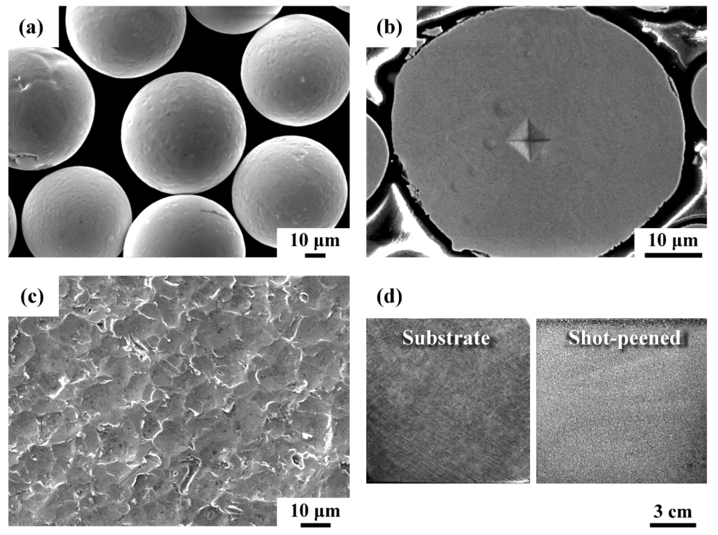
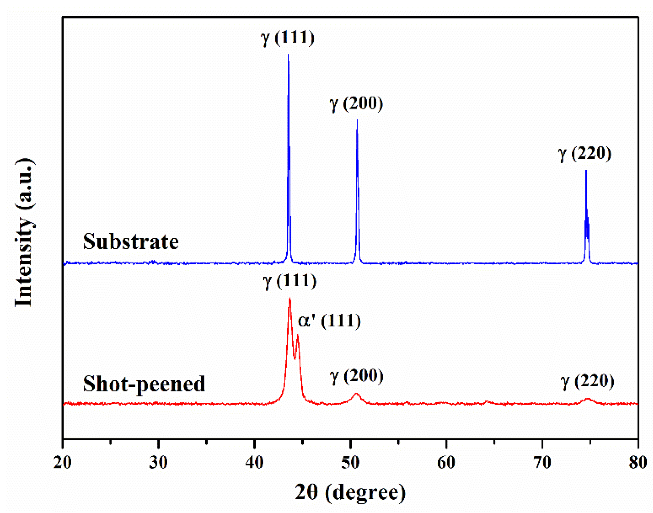
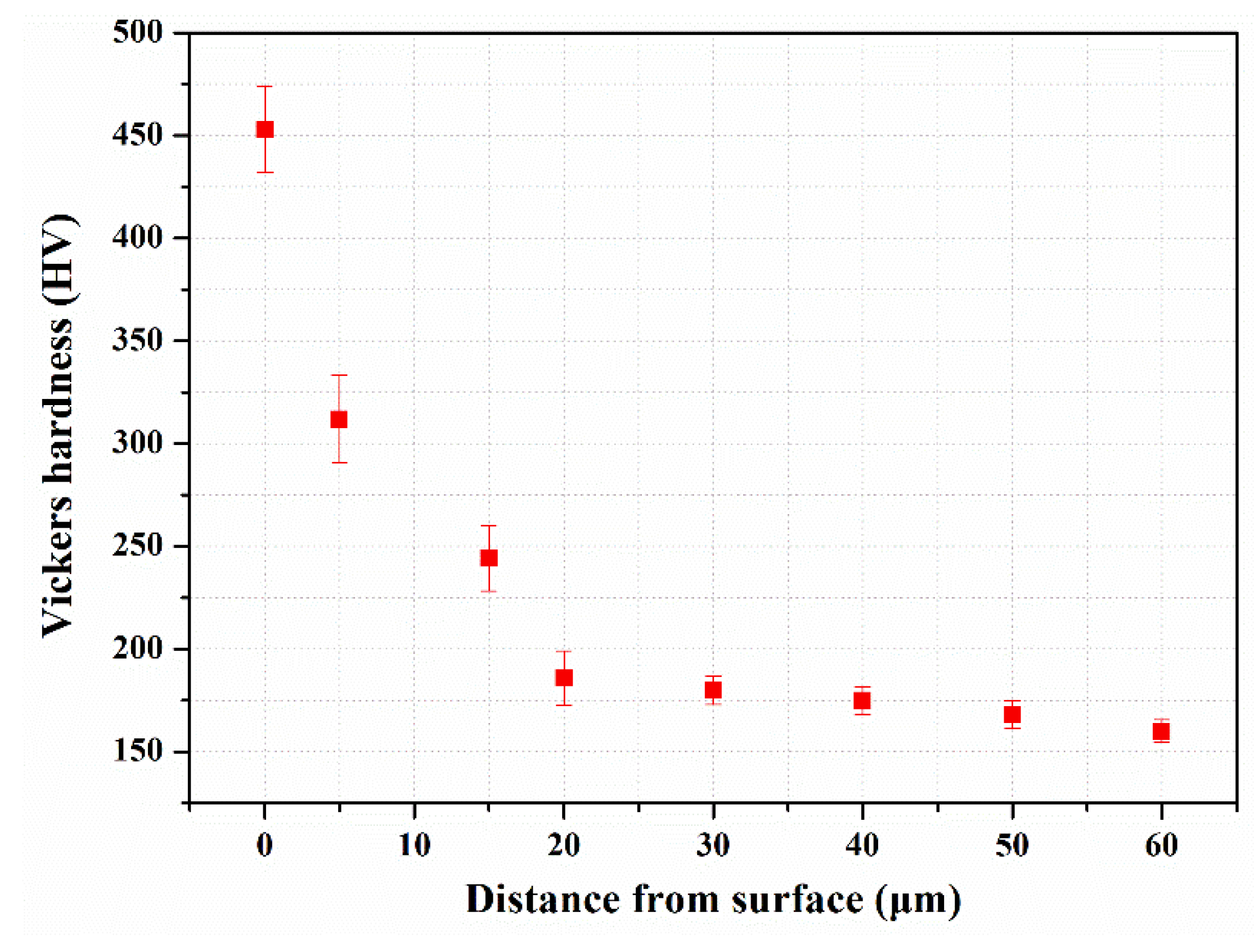
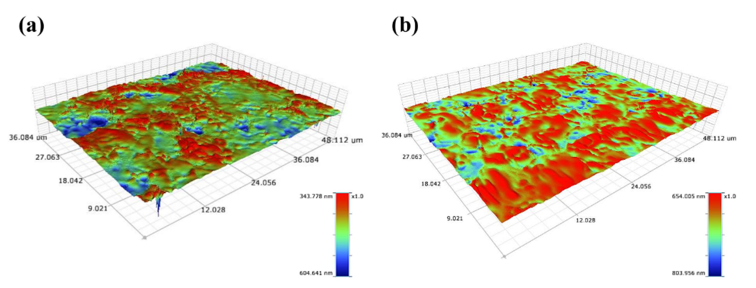
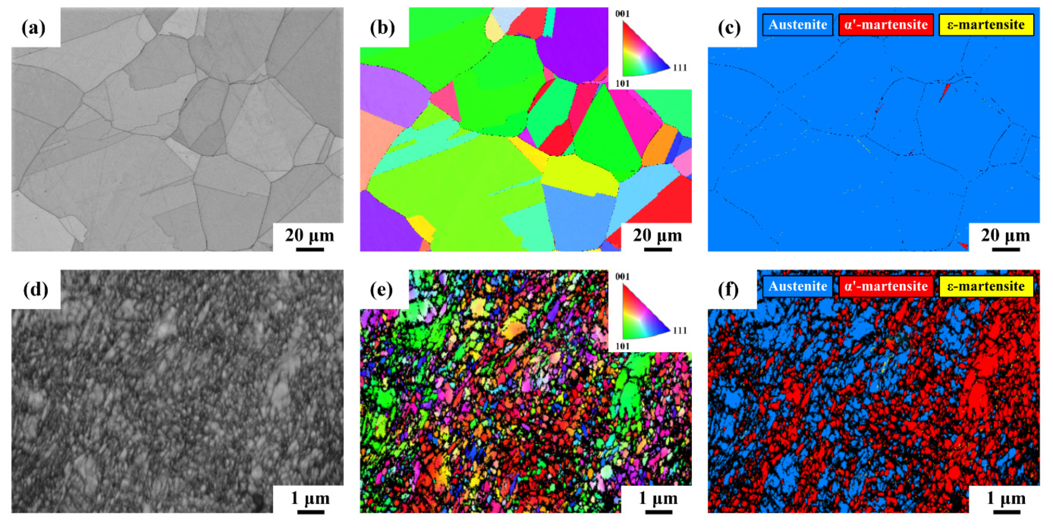
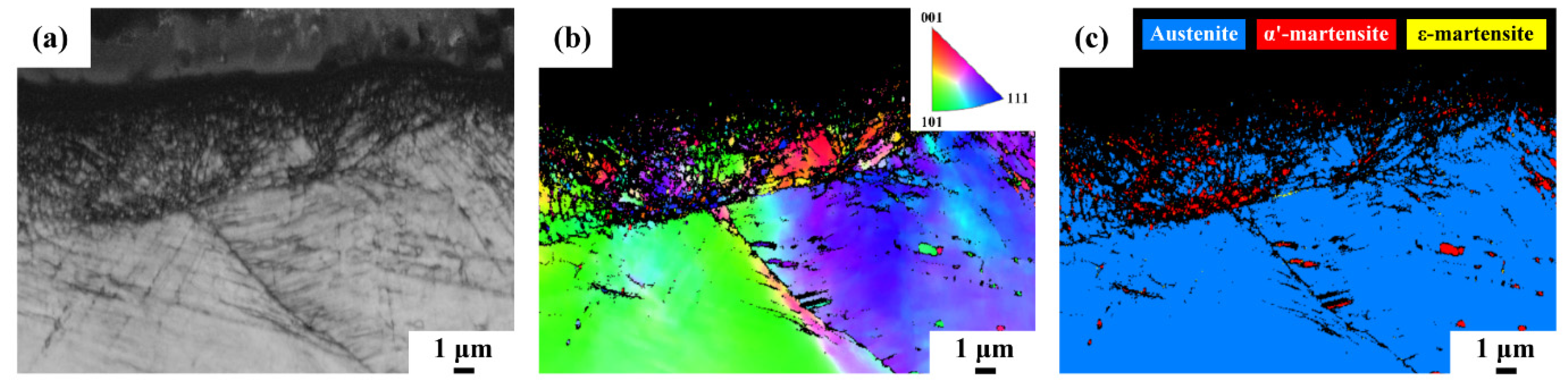
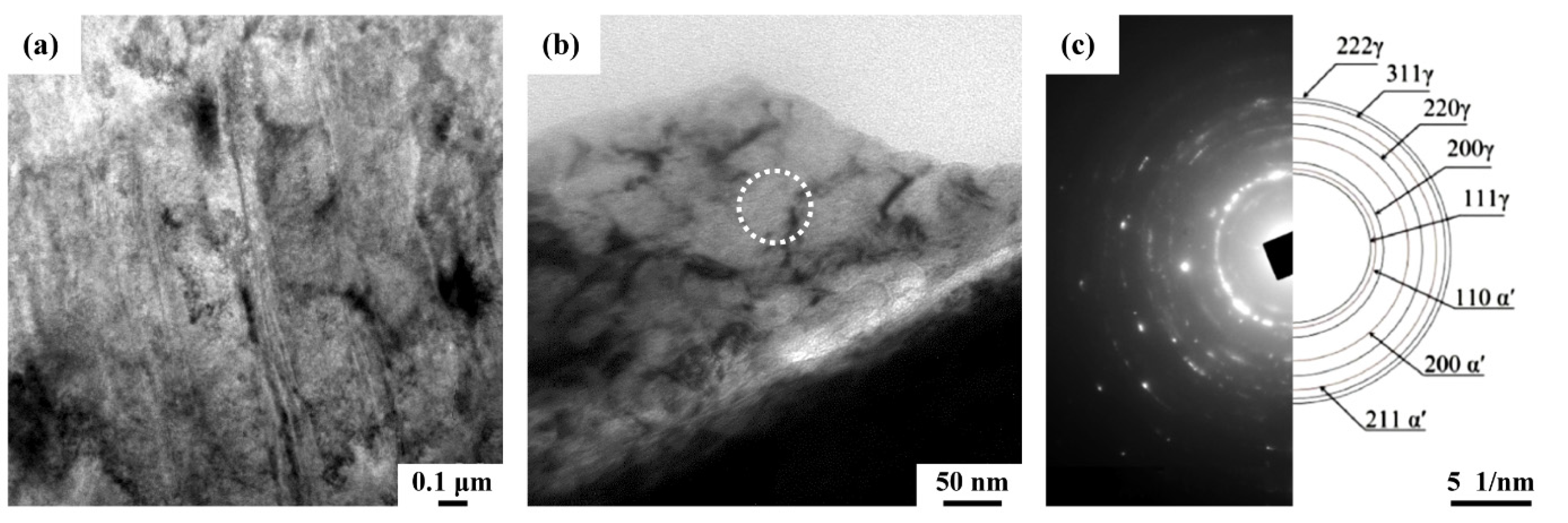
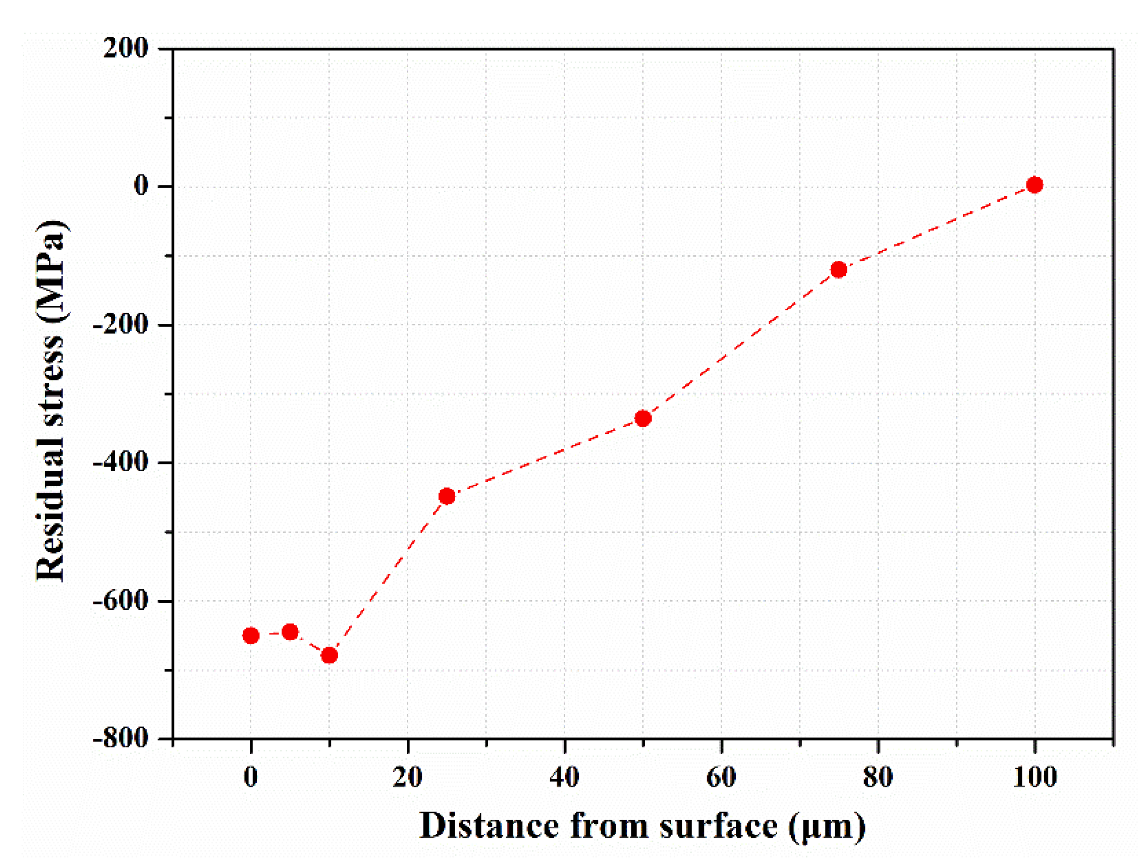
  • Micro-shot peening with 50–80 μm amorphous particles resulted in a minor increase in surface roughness to Ra 0.24 μm, but the surface hardness of the shot-peened sample was as high as HV 453. Compressive residual stress above 600 MPa was found in the zone near the surface. TEM micrograph and IPF map confirmed the formation of a nanograined structure in the severely shot-peened layer.
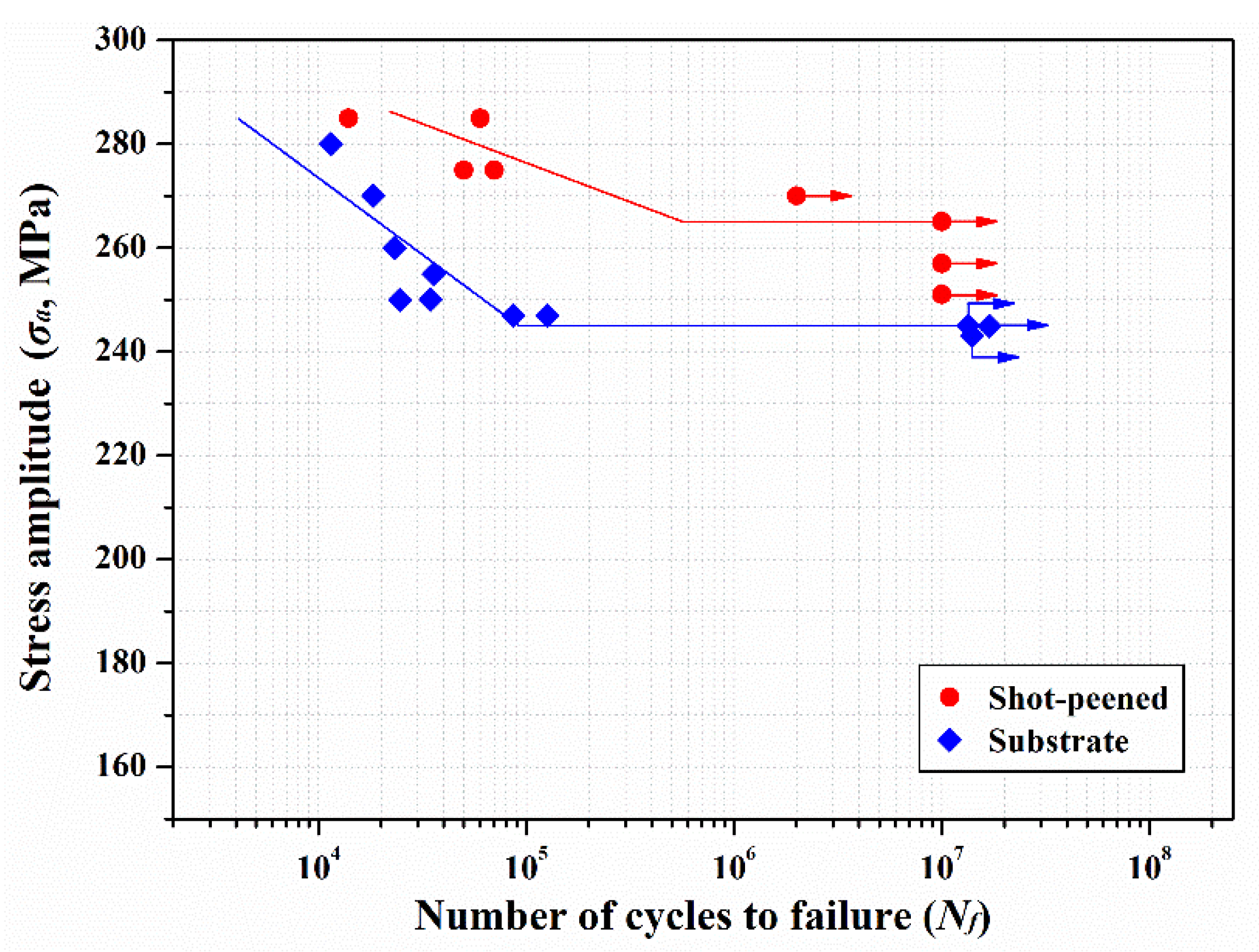
  • The results indicated that the fatigue limit of the substrate was about 245 MPa, which was a little lower than its yield strength. The fatigue limit of the shot-peened sample was about 265 MPa, which was higher than the yield strength of the substrate. It was deduced that the dislocation motion was retarded by the introduction of hardened layer, fine-grained structure and compressive residual stress in the shot-peened sample, resulting in improving its fatigue performance. However, a short fatigue life of the shot-peened sample resulted at the applied stress over 270 MPa, which could be due to the breakdown of thin shot-peened layer under high stresses.
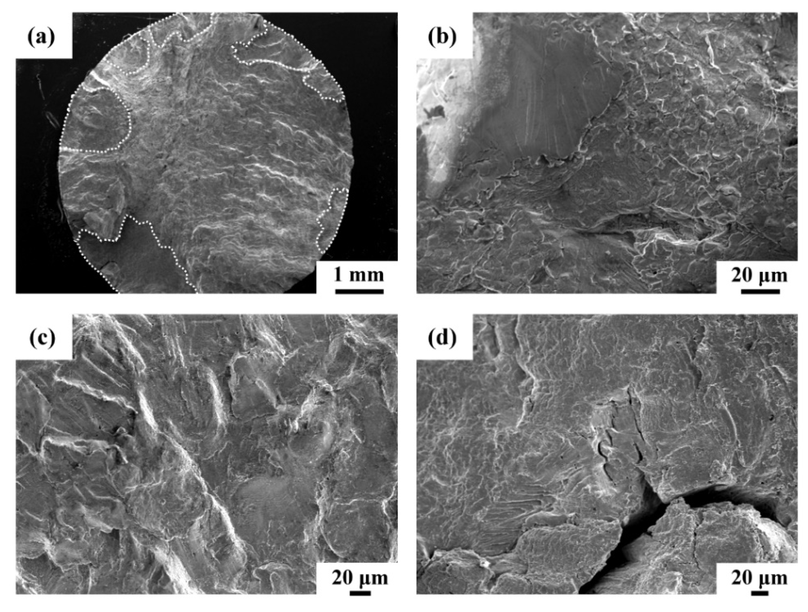
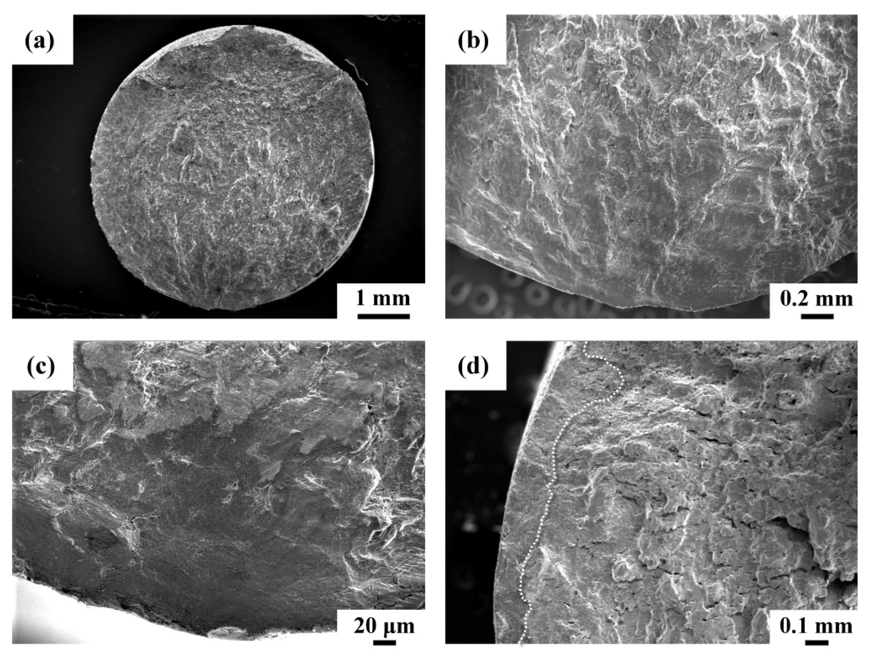
  • Fatigue fratographs showed multiple crack initiations around the outer profile of the 304 substrate. By contrast, cracks were obviously suppressed in the shot-peened sample. Transgranular fatigue fracture with rubbed surface feature was more likely to be seen at the crack initiation sites, particularly in the shot-peened sample. The combination of the fine-grained structure, hardened surface and compressive residual stress was deduced to retard the dislocation motion during the fatigue crack initiation stage, thus improving the fatigue performance of the shot-peened sample.

Author Contributions

Experiment, Y.-H.C. and T.-C.C.; formal analysis, H.-B.L.; writing—original draft preparation, L.-W.T.; writing—review and editing, L.-W.T.; funding acquisition, L.-W.T. All authors have read and agreed to the published version of the manuscript.

Funding

This research was funded by the Ministry of Science and Technology, ROC (Contract No. MOST 109-2221-E-019-023-MY3).

Data Availability Statement

Data presented in this article are available at request from the corresponding author.

Acknowledgments

The authors are grateful to the Ministry of Science and Technology (National Taiwan University) for the assistance in TEM (EM003800) examinations. The authors are grateful to the Core Facility Center of National Cheng Kung University (OTHER002200) for the usage of 3D optical profiler. Thanks to Ministry of Science and Technology (National Central University) for the assistance in sample preparations using FEI Versa 3D High-Resolution Dual-Beam Focus-Ion-Beam System (EM023500). The authors would also like to thank for the data from Thermal Analysis System of Instrumentation Center, National Taiwan University.

Conflicts of Interest

The authors declare no conflict of interest.

References

  1. Kumar, D.; Idapalapati, S.; Wang, W.; Narasimalu, S. Effect of Surface Mechanical Treatments on the Microstructure-Property-Performance of Engineering Alloys. Materials 2019, 12, 2503. [Google Scholar] [CrossRef] [Green Version]
  2. Strzelecki, P.; Mazurkiewicz, A.; Musiał, J.; Tomaszewski, T.; Słomion, M. Fatigue life for different stress concentration factors for stainless steel 1.4301. Materials 2019, 12, 3677. [Google Scholar] [CrossRef] [Green Version]
  3. Weidner, A.; Lippmann, T.; Biermann, H. Crack initiation in the very high cycle fatigue regime of nitrided 42CrMo4 steel. J. Mater. Res. Technol. 2017, 32, 4305–4316. [Google Scholar] [CrossRef]
  4. Vielma, A.; Llaneza, V.; Belzunce, F. Effect of coverage and double peening treatments on the fatigue life of a quenched and tempered structural steel. Surf. Coat. Technol. 2014, 249, 75–83. [Google Scholar] [CrossRef]
  5. Farrahi, G.; Ghadbeigi, H. An investigation into the effect of various surface treatments on fatigue life of a tool steel. J. Mater. Process. Technol. 2006, 174, 318–324. [Google Scholar] [CrossRef]
  6. Maleki, E.; Unal, O.; Amanov, A. Novel experimental methods for the determination of the boundaries between conventional, severe and over shot peening processes. Surf. Interfaces 2018, 13, 233–254. [Google Scholar] [CrossRef]
  7. Segurado Frutos, M.E.; Belzunce Varela, F.J.; Fernández Pariente, I. Mechanical surface treatments to optimize the fatigue behavior of quenched and tempered high strength steels. Int. J. Adv. Manuf. Technol. 2018, 96, 1225–1235. [Google Scholar] [CrossRef]
  8. Fargas, G.; Roa, J.; Mateo, A. Effect of shot peening on metastable austenitic stainless steels. Mater. Sci. Eng. A 2015, 641, 290–296. [Google Scholar] [CrossRef] [Green Version]
  9. Amanov, A.; Karimbaev, R.; Maleki, E.; Unal, O.; Pyun, Y.S.; Amanov, T. Effect of combined shot peening and ultrasonic nanocrystal surface modification processes on the fatigue performance of AISI 304. Surf. Coat. Technol. 2019, 358, 695–705. [Google Scholar] [CrossRef]
  10. Palacios, M.; Bagherifard, S.; Guagliano, M.; Fernández Pariente, I. Influence of severe shot peening on wear behaviour of an aluminium alloy. Fatigue Fract. Eng. Mater. Struct. 2014, 37, 821–829. [Google Scholar] [CrossRef]
  11. Morita, T.; Noda, S.; Kagaya, C. Influences of fine-particle bombarding and conventional shot peening on surface properties of steel. Mater. Trans. 2014, 55, 646–652. [Google Scholar] [CrossRef] [Green Version]
  12. Harada, Y.; Fukaura, K.; Haga, S. Influence of microshot peening on surface layer characteristics of structural steel. J. Mater. Process. Technol. 2007, 191, 297–301. [Google Scholar] [CrossRef]
  13. Kovacı, H.; Bozkurt, Y.; Yetim, A.; Aslan, M.; Çelik, A. The effect of surface plastic deformation produced by shot peening on corrosion behavior of a low-alloy steel. Surf. Coat. Technol. 2019, 360, 78–86. [Google Scholar] [CrossRef]
  14. Böhm, M.; Kowalski, M.; Niesłony, A. Influence of the elastoplastic strain on fatigue durability determined with the use of the spectral method. Materials 2020, 13, 423. [Google Scholar] [CrossRef] [PubMed] [Green Version]
  15. Gartner, N.; Kosec, T.; Legat, A. Monitoring the corrosion of steel in concrete exposed to a marine environment. Materials 2020, 13, 407. [Google Scholar] [CrossRef] [PubMed] [Green Version]
  16. Xiong, Y.; Yue, Y.; He, T.; Lu, Y.; Ren, F.; Cao, W. Effect of rolling temperature on microstructure evolution and mechanical properties of AISI 316LN austenitic stainless steel. Materials 2018, 11, 1557. [Google Scholar] [CrossRef] [Green Version]
  17. Hsu, C.-H.; Chen, T.-C.; Huang, R.-T.; Tsay, L.-W. Stress corrosion cracking susceptibility of 304L substrate and 308l weld metal exposed to a salt spray. Materials 2017, 10, 187. [Google Scholar] [CrossRef] [Green Version]
  18. Yu, C.; Shiue, R.-K.; Chen, C.; Tsay, L.-W. Effect of low-temperature sensitization on hydrogen embrittlement of 301 stainless steel. Metals 2017, 7, 58. [Google Scholar] [CrossRef] [Green Version]
  19. Fu, P.; Jiang, C.; Wu, X.; Zhang, Z. Surface modification of 304 steel using triple-step shot peening. Mater. Manuf. Process. 2015, 30, 693–698. [Google Scholar] [CrossRef]
  20. Ni, Z.; Wang, X.; Wang, J.; Wu, E. Characterization of the phase transformation in a nanostructured surface layer of 304 stainless steel induced by high-energy shot peening. Phys. B Condens. Matter 2003, 334, 221–228. [Google Scholar] [CrossRef]
  21. Jung, J.S.; Pyoun, Y.; Cho, I. Effect of Ultrasonic and Air Blast Shot Peening on the Microstructural Evolution and Mechanical Properties of SUS304. J. Korean Phys. Soc. 2009, 54, 1161–1166. [Google Scholar]
  22. He, Y.; Lee, H.S.; Yang, C.W.; Lee, J.H.; Shin, K. Microstructural evolution of a nanostructure of shot peened 304 stainless steel upon heat treatment. Sci. Adv. Mater. 2017, 9, 1942–1946. [Google Scholar] [CrossRef]
  23. Yeh, T.K.; Huang, G.R.; Wang, M.Y.; Tsai, C.H. Stress corrosion cracking in dissimilar metal welds with 304L stainless steel and Alloy 82 in high temperature water. Prog. Nucl. Energy 2013, 63, 7–11. [Google Scholar] [CrossRef]
  24. Unal, O.; Varol, R. Surface severe plastic deformation of AISI 304 via conventional shot peening, severe shot peening and repeening. Appl. Surf. Sci. 2015, 351, 289–295. [Google Scholar] [CrossRef]
  25. Inoue, A.; Yoshii, I.; Kimura, H.; Okumura, K.; Kurosaki, J. Enhanced shot peening effect for steels by using Fe-based glassy alloy shots. Mater. Trans. 2003, 44, 2391–2395. [Google Scholar] [CrossRef] [Green Version]
  26. Li, X.; Zhang, J.; Yang, B.; Zhang, J.; Wu, M.; Lu, L. Effect of micro-shot peening, conventional shot peening and their combination on fatigue property of EA4T axle steel. J. Mater. Process. Technol. 2020, 275, 116320. [Google Scholar] [CrossRef]
  27. De Los Rios, E.R.; Walley, A.; Milan, M.T.; Hammersley, G. Fatigue crack initiation and propagation on shot-peened surfaces in A316 stainless steel. Int. J. Fatigue 1995, 17, 493–499. [Google Scholar] [CrossRef]
  28. Sano, Y.; Obata, M.; Kubo, T.; Mukai, N.; Yoda, M.; Masaki, K.; Ochi, Y. Retardation of crack initiation and growth in austenitic stainless steels by laser peening without protective coating. Mater. Sci. Eng. A 2006, 417, 334–340. [Google Scholar] [CrossRef]
  29. Shiozawa, K.; Lu, L. Very high-cycle fatigue behaviour of shot-peened high-carbon–chromium bearing steel. Fatigue Fract. Eng. Mater. Struct. 2002, 25, 813–822. [Google Scholar] [CrossRef]
Figure 1. The dimensions of rotating beam fatigue specimen. Surface roughness (Ra): substrate 0.178 μm, shot-peened sample 0.240 μm.
Metals 11 01408 g001
Figure 2. Surface morphology of the (a) amorphous shot; (b) the cross section of the shot with a hardness indentation; (c) shot-peened surface; (d) the macro-appearance of the substrate and the shot-peened sample.
Metals 11 01408 g002
Figure 3. X-ray diffraction (XRD) patterns of the substrate and shot-peened sample.
Metals 11 01408 g003
Figure 4. Hardness depth profile of the shot-peened sample.
Metals 11 01408 g004
Figure 5. 3D contour profiles of the (a) ground substrate and (b) shot-peened sample.
Metals 11 01408 g005
Figure 6. Top surface microstructures of the 304 substrate (ac) and shot-peened sample (df). (a,d) Scanning electron micrographs; (b,e) the corresponding inverse pole figure (IPF) maps; (c,f) EBSD phase maps.
Metals 11 01408 g006
Figure 7. (a) Scanning electron micrograph, (b) the corresponding inverse pole figure (IPF) map and (c) the EBSD phase map of the shot-peened sample in cross-sectional view.
Metals 11 01408 g007
Figure 8. TEM images of the (a) shot-peened layer, (b) FIB sample and (c) the SADP of the sample in (b).
Metals 11 01408 g008
Figure 9. The residual stress profile from the shot-peened surface to the internal substrate.
Metals 11 01408 g009
Figure 10. Fatigue stress vs. cycle curves of the 304 substrate and shot-peened samples.
Metals 11 01408 g010
Figure 11. (a) Macro-fatigue appearance of the 304 substrate, (b,c) fracture features at the crack initiation sites, (d) transgranular crack growth with striations.
Metals 11 01408 g011
Figure 12. (a) Macro-fatigue appearance of the shot-peened sample, (b) rubbed zone at the crack initiation site, (c) the same area of (b) at higher magnification, (d) rubbed layer around the circumference.
Metals 11 01408 g012
Table 1. The roughness values (in μm) of the tested samples.
RoughnessRa 1Rp 2Rv 3
Sample
Substrate0.1780.3430.604
Shot peened0.2400.6540.803
1 Ra: arithmetic mean deviation. 2 Rp: maximum profile peak height. 3 Rv: maximum profile valley depth.
Publisher’s Note: MDPI stays neutral with regard to jurisdictional claims in published maps and institutional affiliations.

