Article

Rationally-Based Structural Design of Welded Plate Panels

by
Ahmed Hammad
1,
Yehia Abdel-Nasser
1,
Cristina Churiaque
2 and
José María Sánchez-Amaya
2,*
1
Department of Naval Architecture and Marine Engineering, Faculty of Engineering, Alexandria University, Alexandria 21544, Egypt
2
Department of Materials Science and Metallurgical Engineering and Inorganic Chemistry, School of Engineering, University of Cádiz, 11519 Puerto Real, Spain
*
Author to whom correspondence should be addressed.
Metals 2021, 11(9), 1381; https://doi.org/10.3390/met11091381
Submission received: 30 June 2021 / Revised: 28 July 2021 / Accepted: 16 August 2021 / Published: 31 August 2021
(This article belongs to the Special Issue Design of Welded Steel Structures)

Abstract

:
This study predicts the behavior of welded plate panels (unstiffened plates) with different geometrical properties (slenderness ratio and aspect ratio) in order to address a rational structural design procedure, as these parameters are of great importance from a structural design perspective. Nonlinear finite element analysis has been used to simulate the butt-welding process of plate panels, giving the three-dimensional distribution of distortion and residual stresses induced by welding through the design of a moving heat source. The numerical results are validated with published experimental measurements. The effect of geometrical properties such as slenderness ratio β and aspect ratio a/b on the creation of welding-induced imperfections (distortion and residual stresses) have been investigated in this work. These geometrical properties influence the creation of the welding-induced imperfections, which in turn affect the load-carrying capacity of the plate panels. Three different plate slenderness ratios with three different aspect ratios have been studied. It is concluded that increasing the plate aspect ratio can highly increase the out-of-plane distortion magnitude as well as the compressive residual stress. The plates with high slenderness ratio (thin thicknesses) are highly affected by increasing plate aspect ratio a/b. As the slenderness ratio β increases, the reduction in the ultimate strength due to the existence of welding-induced imperfections highly decreases. Slenderness ratio β can highly affected the ultimate strength of plates with smaller aspect ratio more than plates with higher aspect ratio.

1. Introduction

Welding technology is one of the most important manufacturing operations for a wide range of applications, especially for the shipbuilding industry, because of its high productivity. During the heating and cooling process, the expansion and contraction of the weld metal and adjacent base metal result in imperfections such as distortions and welding-induced residual stress. Such imperfections lead to misalignment, requiring an additional expense and time-consuming rework to straighten such structures to be ready for assembly, resulting in altering the structural strength. Several researchers have used the three-dimensional finite element technique to predict thermal history, welding-induced residual stresses and out-of-plane distortion, validating it with experimental measurements. Because of these imperfections, the specified structural members may not attain their design load that is supposed to be carried and will require extra man-hours to remove these imperfections. Control of these imperfections and their impact on the structure’s ultimate load-carrying capacity of a plate panel are investigated in the present study.
Three-dimensional FEM of a plate subjected to double ellipsoidal moving heat source has been developed by Chen et al. [1,2] to simulate the welding process using ANSYS in order to predict the temperature field, distortions and residual stresses induced by butt welding process. Heating speed, heat input, welding sequences, plate thickness and finite element size have been investigated by Chen et al. [3,4] and were proved to have a significant impact on the welding response. It is concluded that the associated thickness of the plate does not affect the deformed pattern but has a significant effect on the deformation magnitude. Thermo-elastic-plastic FEM is used by Zhang and Wang [5] to study the effect of boundary condition on the welding-induced imperfections (residual stress and distortion) of a stiffened-panel. The results showed that mechanical boundary conditions mainly affect the welding deformation and have little influence on the residual stress. The effect of Hybrid Laser Arc Welding (HLAW) factors on the quality of naval steel fillet joints has been investigated by Churiaque et al. [6]. The effects of various processing parameters such as laser power, welding speed, wire feed rate and HLAW process configuration have been investigated. FEM simulations were performed to estimate residual stresses and distortion of welded parts, providing excellent agreement with the measured experimental results. Wang et al. [7] proposed an elastic FE analysis approach with inherent deformation and interface elements to predict welding distortion of welded joints, in particular large and complex welded structures, and an intermittent zigzag welding procedure to reduce welding distortion due to buckling behavior.
Hashemzadeh et al. [8] performed a numerical study by a 3D finite element simulation on butt weld with dissimilar thickness of thin stainless-steel plates. It was concluded that changing the plate thickness has a significant effect on the vertical deflection, especially for thin plates. The effect of changing welding sequence on minimizing welding-induced imperfections in 304 butt-welded stainless plates was investigated by Choobi et al. [9] using numerical simulation. Deng and Murakawa [10] used FEM to simulate the welding process of a thin plate butt joint. Meanwhile, experiments are being conducted to measure the deformation of the weld. In addition, the thermo-elastic-plastic FEM based on the inherent strain theory is often used to model welding deformation in the same butt joint. More recently, Hammad et al. [11] have developed a three-dimensional coupled thermo-elastic-plastic FEM with ABAQUS to simulate the volumetric heat flux distributions of the HLAW process. The FEM is verified by comparison with experimental measurements. In addition, the effect of changing welding sequence on the semi-industrial scale stiffened panel has been also studied. A numerical simulation based on FE modeling has been developed by Hammad et al. [12] to investigate the effect of different parameters on the magnitude of welding imperfections of a fabricated T-girder, such as geometrical properties and welding sequence. Moreover, a parametric study with two variables (geometrical properties and welding sequence) is produced to choose the optimum geometry with the optimum welding sequence based on minimum steel weight and out-of-plane distortion.
Three-dimensional analyses of thermo-elastic-plastic finite elements were carried out by Chen and Soares [13] to predict the effects of plate configurations on weld-induced deformations and the strength of fillet welded plates. The ultimate strength obtained is compared with the results of some simplified methods and with the Common Structural Rules (CSR) of the International Association of Classification Societies (IACS). They conclude that the presence of residual stress results in the overall longitudinal strength of plates being decreased by 5–7%. Gannon et al. [14] used nonlinear finite element analysis to simulate the welding of stiffened plates and study the effect of welding-induced residual stress and distortion on ship hull girder ultimate strength. For the welded stiffened plates under axial compression, load-shortening curves are generated, and the results are compared with the load-shortening curves derived from the IACS Common Structural Rules and published experimental data. Tekgoz et al. [15] investigated the effect of residual stress on the ultimate strength through a moving heat source by changing the heat input, heat speed, plate thickness and welding sequence. Kim et al. [16] proposed an advanced empirical formulation by applying the concept of the initial deflection index (IDI) to predict plate ultimate strength performance under longitudinal compression. The empirical formulation obtained showed good agreement with the numerical simulation results (R2 = 0.99). Anyfantis [17] developed an approach for clarifying the influence of geometrical distortions to the buckling capacity of stiffened panels. It was concluded that when the stiffened panel involves global distortion such that maximum global bending stress develops at the plate, then only local plate and web distortions are significant, while stiffener and global distortion may be neglected from the analysis. In order to address a rational structural design procedure, Chaithanya et al. [18] carried out a parametric form of non-linear FE analysis using ABAQUS under an axial loading condition to predict the behavior and buckling strength. Khedmati et al. [19] studied the impact of geometric imperfections under combined axial compression and lateral pressure on the overall strength and load-carrying capability of aluminum stiffened plates. It is confirmed that the assessment of the ultimate strength of the panels by analyzing non-linear finite elements is highly dependent on the type of imperfections, particularly the geometric ones.
Fu et al. [20] developed a coupled thermal and mechanical 3D finite element model to investigate the influence of boundary conditions on welding imperfections in T-joint welds. It was concluded that the vertical displacement, angular distortion, transverse shrinkage and transverse residual stress depend significantly on the mechanical boundary conditions. The effect of changing welding sequence and stiffener shape on the welding distortion of stiffened panels has been studied by Shadkam et al. [21]. The thermo-elastic-plastic FE analysis is employed to estimate the inherent deformations of different SM490A steel welded joints.
The compressive axial ultimate strength of fillet-welded steel-plated ship structures subjected to uniaxial compression is investigated by Chen and Soares [22]. The influence of residual stress on the stiffened plate’s axial strength is investigated and addressed. Xia et al. [23] used nonlinear finite element analyses to investigate the combined impact of initial deflections, welding residual stresses, and the length and position of cracks on the ultimate strength of cracked plates under uniaxial compression. In the present study, numerical simulation based on a finite element model is used to simulate the MAG butt-welding process. The numerical results (temperature distribution, out-of-plane distortion, and longitudinal residual stresses) are validated with experimental measurements published by Kim et al. [24]. The influence of geometrical properties such as slenderness ratio β and aspect ratio a/b on the creation of welding-induced imperfections (out-of-plane distortion and residual stresses) have been investigated in this work to make an appropriate selection of design parameters. The effect of weld-induced imperfections on structural designs is of great importance as it is important for predicting the ultimate strength of unstiffened plate under different loading conditions. Many of the current studies take traditional initial imperfections as a mixture of geometric distortion and residual stress. This work specifically considers the three-dimensional FEM results of the imperfections caused by welding as the initial state for the ultimate strength analysis. Non-linear finite element analysis was performed under uniaxial compression to predict the ultimate strength behavior of the plate panels. Furthermore, the effect of changing geometrical properties such as slenderness ratio β and aspect ratio a/b on the ultimate strength behavior has been studied in order to address a rational structural design procedure, as these parameters are of great importance from a structural design perspective.

2. Mathematical Modeling

2.1. Thermal Analysis

The heat flow equation in Abaqus software is generated using the energy conservation equation and the Fourier law, which are both formulated using the weighted residuals technique criterion. The equation in the program is defined as follows [24]:
  V ρ U t δ T   d V + V δ T x α . ( λ T x α ) d V = V δ T   q V d V + V δ T   q S d S    
where λ is a thermal conductivity (W/(m⋅K)), U is the internal energy (J), ∂U/∂t is the material time rate of internal energy (the specific heat (J⋅K−1⋅kg−1), cp(T) being given by ∂U/∂T assuming the volume is held constant), q V is the volumetric heat source (J⋅K−1⋅m−3), T = T ( x α , t ) is the temperature, q S is a boundary heat flux, δ T is a variational function and ρ is the density (kg/m3).
Equation (1) is completed by the initial condition t = 0: T = To, and the Dirichlet and Neumann form boundary conditions. Newton’s law governs heat exchange with the environment, taking into account convection, radiation and evaporation heat loss.

2.2. Heat Source Modeling

To simulate the welding heat source in Abaqus software [25], the Goldak double-ellipsoid heat flux distribution was employed in this study. The heat flux distribution, as depicted in Figure 1, incorporates two separate ellipses. The power densities of the double heat flux distributions inside the front and rear heat source quadrants, respectively, are defined by q f ( x , y , z )   and q r ( x , y , z ) [26,27].
The first semi-ellipsoid, which is placed in front of the welding arc, has the following heat flux equation:
q v f ( x , y , z ) = 6 3 ( f f Q ) ab c f π π exp ( 3 x 2 a 2 3 y 2 b 2 3 z 2 c f 2 )   z 0
where a, b and cf are geometry parameters, ff is the heat input proportion in the front part and Q = η I U is the heat flux of the arc where η, I, U are the efficiency, current and voltage of the welding process, respectively, and (x, y, z) are the coordinates of the point of consideration.
For any point (x, y, z) within the second semi-ellipsoid, which covers the rear portion of the arc, the heat flux is described as:
q v r ( x , y , z ) = 6 3 ( f r Q ) ab c r π π exp ( 3 x 2 a 2 3 y 2 b 2 3 z 2 c r 2 )   z 0
where cr is a geometry parameter, fr is the heat input proportion in the rear part and f f + f r = 2 .
Modeling a moving heat source is a typical transient process. While the heat source is moving, the heat energy is kept constant; however, the location of the heat source center changes with time.
The moving welding heat source is modeled in Abaqus FEA by employing an extra numerical subroutine of DFLUX built in the Fortran programming language to generate volumetric heat flux distributions that are dependent on position and time [19]. The subroutine takes into account the heat source’s power distribution, position, movement and motion direction. The position of the heat source center is computed for each time step based on the speed of the source used.

2.3. Mechanical Analysis

When it comes to analyzing mechanical phenomena, the Abaqus FEA calculation program is based on classical equilibrium Equation (4). Constitutive relationships (5), beginning conditions (6) and boundary conditions complete out these equations. The mechanical analysis in elastic-plastic range is calculated as follows [27,28]:
σ ˙ ( x α , t ) = 0 ,   σ ˙ = σ ˙ T  
σ ˙ = D ε ˙ e + D ˙ ε e ,   ε e = ε ε p ε T p h  
σ ( x α , t 0 ) = σ ( x α , T S ) = 0 ,   ε e ( x α , t 0 ) = ε e ( x α , T S )  
where σ = σij) is the stress tensor, xα describes the location of the considered point (material particle), (°) is the inner exhaustive product and D = D(T) is a tensor of temperature-dependent material properties.
The total strain is defined as a sum of elastic ε e , plastic ε p and thermal ε T h strains:
ε t o t a l = ε e + ε p + ε T h  
Hooke’s law is used to represent elastic deformations in an isotropic structure in this simulation. The plastic strain is calculated using a plastic flow model that follows Huber−Mises’ plasticity condition [29].

3. Materials and Methods

3.1. Welding Experimental Procedure

The butt-welded joint of two SM400A steel plates taken from Kim et al. [24] with breadth b = 500 mm and length a = 300 mm is considered to validate the present FEM. The material, physical and mechanical properties have important influence on distortion. As the weld temperature rises, the yield strength, elasticity modulus and steel thermal conductivity decreases, while the specific heat and thermal expansion coefficient increase. The base material temperature dependent thermal and mechanical properties are shown in Figure 2 [30], while the chemical compositions of the base and weld filler metal are presented in Table 1. The experimental temperature measurements were determined using thermo-couples. For this purpose, two thermo-couples (TC1 and TC2) were attached to the top surface along the mid-span of the plate at different distances from the weld center line (−15 mm, −30 mm), as shown in Figure 3.
The welding process is modeled as an MAG single pass weld with the parameters shown in Table 2, with welding current I = 240 A, welding voltage U = 28 V and welding speed v = 300 mm/min. The following values are chosen for the other parameters: the convective heat transfer coefficient k = 10 W/m2·K, the efficiency of heat input η = 85% and the emissivity coefficient ε = 0.9.

3.2. FEM Model Description

In this part, numerical simulation was performed to find out the temperature history, out-of-plane distortions and welding-induced residual stresses to validate the effectiveness of the proposed model with the published experimental measurements [24]. Numerical analysis of thermo-mechanical phenomena of the butt-welding process within the Abaqus (2017, Dassault Systemes Simulia, Johnston, IA, USA) FEA system was divided into thermal phenomena analysis and mechanical phenomena analysis. The temperature field of the welded joint was calculated in the thermal analysis. The shape and width of the region affected by the melted area and heat were determined. In the next stage, an analysis of mechanical phenomena was conducted, in which the results from the previous analysis (temperature histories) were the input data. In the mechanical analysis, an elastic and perfectly plastic material behavior model is assumed. The geometry of the welded plates is shown in Figure 3. The heat source model takes the shape of the weld bead with the parameters shown in Table 3.

3.3. Finite Element Mesh

Because of the high temperature gradient, a substantial density of the finite element mesh was utilized in the numerical model provided in the welding line. The finite element meshes used for both thermal and structural analyses are similar, except for the type of element. To reduce the calculation time while retaining reasonable accuracy, finer meshes were divided into the fusion zone and surrounding HAZ, while coarser meshes were divided into the outer region. The mesh consists of 9120 finite elements. As the distance from the weld bead increases, the size of the finite elements becomes greater, as presented in Figure 4. The elements DC3D8 and C3D8 are used to discrete the geometry during the thermal and stress analysis stages, respectively, using ABAQUS standard software.

3.4. Ultimate Strength Validation

A limit state is a situation in which a specific structural component or an entire structural system fails to execute its intended purpose. Four types of limit states are relevant: serviceability limit states (SLS), ultimate limit states (ULS), fatigue limit states (FLS) and accidental limit states (ALS) [32]. The present work is concerned with ULS.
Along with stiffened structures, the plate panel (or unstiffened panel) is considered the primary structural component of ships and offshore structures. The effect of weld-induced imperfections on structural designs is of great importance as it is important for predicting the behavior of stiffened and unstiffened plate elements under different loading conditions. Many of the current studies take traditional initial imperfections as a mixture of geometric distortion and residual stress. This section specifically considers the three-dimensional FEM results of the imperfections caused by welding as the initial state for the ultimate strength analysis. The plate slenderness is defined as [13]:
β = b t   σ 0 E  
where b is the plate width, t is the plate thickness, σ 0 is yield stress and E is the Young’s modulus of elasticity.
Numerical modeling of the ultimate buckling strength analysis of a plate panel under uniaxial compression has been analyzed and validated with the results of Tekgoz et al. [15]. The structural models analyzed here are shown in Figure 5. The length, breadth and thickness of the single plate are a = 400 mm, b = 300 mm and t = 6 mm, respectively. The ultimate strength is analyzed based on the finite element method using the commercial software Abaqus. The applied load is uniaxial compression which is applied in one end section in the axial direction. Eight-node quadrilateral solid elements have been used to model the plate. C3D8R elements of the commercial software Abaqus [25] have been used in the structural analysis. The boundary conditions of ultimate strength assessment for single plate are shown in Figure 5. The yield stress, Young’s modulus and Poison’s coefficient of the material are considered as 350 MPa, 205 GPa and 0.297, respectively. The material properties have been taken from Gery et al. [33].

3.5. Study of Changing Geometrical Properties

Imperfections such as out-of-plane distortion and welding residual stresses are initialized in the welded plates during the welding process. The existence of such imperfections depends on many parameters, such as: welding current, voltage, welding speed, sequence of welding, geometric properties and constraints applied to the welded model during welding process. The welding imperfections can also prevent the structure from sustaining its intended design load that is supposed to be carried. Furthermore, the presence of such imperfections would increase the processing time needed for manufacturing due to the extra time taken for corrective works such as straightening, modification and trim processes. The effect of geometrical properties (such as slenderness ratio and aspect ratio) on the creation of welding imperfections, and in turn the ultimate strength of the plate panel, has been investigated in the present study. Plate slenderness and aspect ratio are important parameters in the ship design process. These parameters affect the fabrication process through determining the amount of welding-induced imperfections and in turn the behavior of the ultimate load-carrying capacity curve of the specified structure. In this section, the geometrical properties of the welded plate panels are modified according to these parameters to investigate its effect on welding-induced imperfections and the ultimate load-carrying capacity.
Table 4 shows the nine different geometrical cases analyzed. It depicts the three different plate slenderness ratios with the three different aspect ratios which have been analyzed in this work. The same welding parameters were assumed for all cases (shown in Table 2), and both the base plate and filler weld metal have the same thermal and mechanical material properties. The heat source model dimensions for the three thicknesses, which consider the shape of the weld bead (Figure 3), are shown in Table 5.

4. Results and Discussion

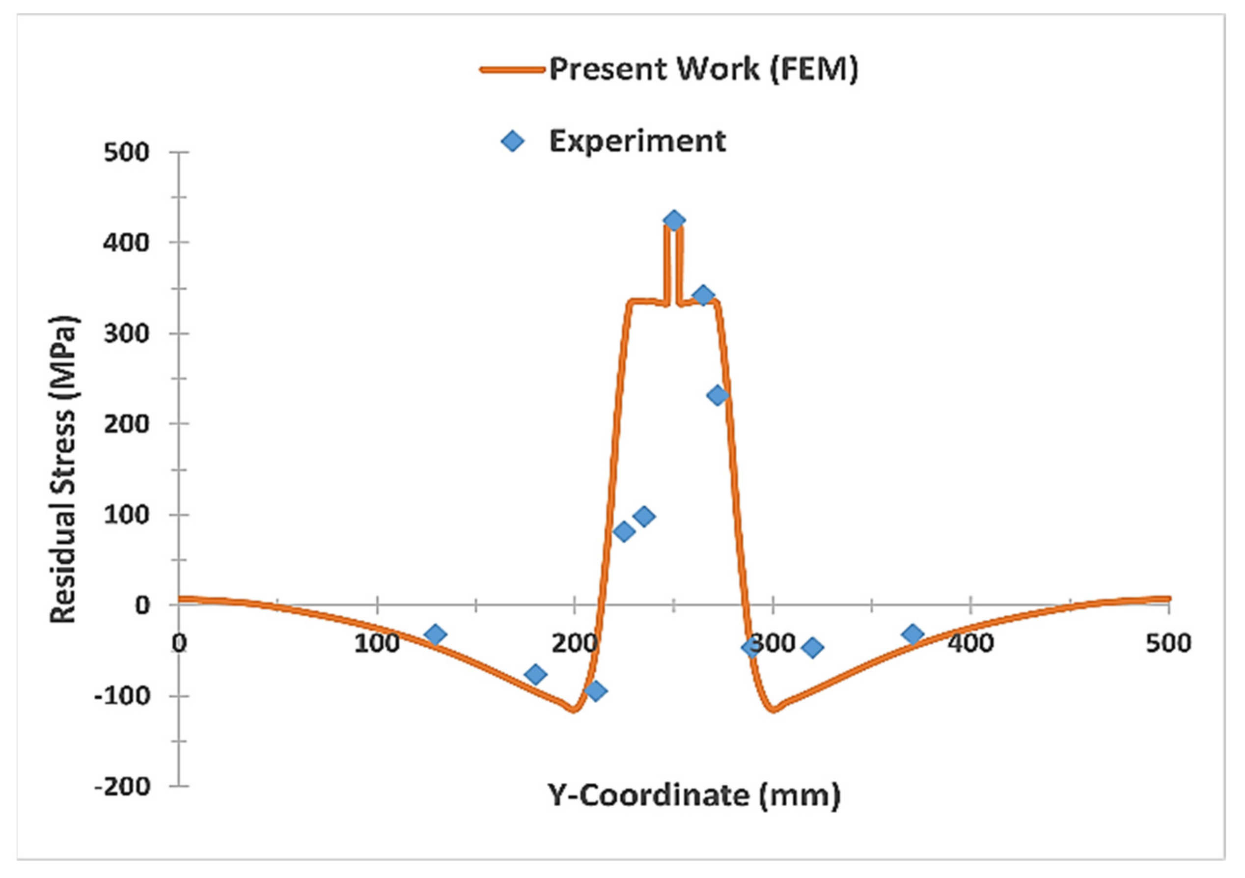
4.1. Numerical Model Validation

The numerical and experimental temperature profiles at the mid-span of the plate are compared to verify the reliability of the developed model. Figure 6 shows a comparison of the numerical and experimental weld temperature profiles. The numerical results show good agreement with the experimental measurements.
Figure 7 shows a comparison of the vertical deflection through the plate panel breath at the mid-span of the welded plates on the top surface along line C-D, obtained by the present work (FEM) and experimental measurements [24]. The present work shows good agreement with the experimental results.
Figure 8 shows the longitudinal stress distribution through the plate panel breath at 180 mm away from welding start point (zero point) on the top surface of the welded plates, obtained by the present work (FEM) and by experimental measurements [24]. The present work shows good agreement with the reported experimental outputs. The residual stress measured in the center of the weld is significantly high because the plates were welded with the wire JIS Z3312 YGW11, which has a significantly higher yield stress value (530 MPa) than the base material [24].

4.2. Ultimate Strength Numerical Validation

The ultimate strength is the real margin of structural load-carrying capability, and its computation necessitates the use of an efficient and accurate nonlinear structural analysis approach. The load-shortening curves of the plate without considering the effect of welding imperfections under uniaxial compression are plotted in Figure 9. The FEA results of the present work shows a good agreement with the published results [15]. The ultimate load-carrying capacity is defined as the peak point.

4.3. Effect of Geometrical Properties on the Welding-Induced Imperfections

Figure 10 reports the results regarding 10 mm thickness plates. Figure 10a shows the vertical deflection distribution at the mid-span along line C-D on the bottom surface of 10 mm plate thickness () with a 1.91 plate slenderness ratio (β) for three different plate aspect ratios (a/b)—Cases 1, 2 and 3 of Table 4. The vertical deflection magnitude reaches its highest value at the mid-span of the plate longitudinal edges (point C) and decreases gradually to zero at plate corners due to the existence of a boundary condition which prevents the plate from moving vertically. It is obvious that as the aspect ratio increases (plate length), the vertical deflection magnitude slightly increases. This is due to the long weld line and the long distance between the boundary condition points at the edge of the model, thus enabling the plate to expand and contract easily.
The longitudinal stress distribution through the plate panel breath at the mid-span of the model along line C-D on the bottom surface of 10 mm plate thickness (t) with a 1.91 plate slenderness ratio (β) for three different plate aspect ratios (a/b) 1, 2 and 3 is plotted in Figure 10b. The plate with a/b = 1 has higher tensile residual stress and a lower compressive residual stress than the other two cases. Case 1 has almost the same residual stress with a slight decrease in tensile and compressive residual stress at the weld centerline and plate edges, respectively.
Figure 11 depicts results in which 8 mm thickness plates are involved. Figure 11a shows the vertical deflection distribution at the mid-span along line C-D on the bottom surface of 8 mm plate thickness (t) with a 2.389 plate slenderness ratio (β) for three different plate aspect ratios (a/b) 1, 2 and 3 (Cases 4, 5 and 6, respectively). The vertical deflection magnitude reaches its highest value at the mid-span plate longitudinal edges (point C) and decreases gradually to zero at plate corners due to the existence of a boundary condition which prevents the plate from moving vertically. From this graph, we can see that the plate aspect ratio a/b has a significant effect on the vertical deflection when the plate slenderness ratio increases (thickness decreases). It is shown that the vertical deflection of the model with a/b = 3 reaches 13 mm, which is relatively high compared with the other two cases which reach 4.25 and 0.3 mm for a/b = 2 and 1, respectively.
The longitudinal stress distribution through the plate panel breath at the mid-span of the model along line C-D on the bottom surface of 8 mm plate thickness (t) with a 2.389 plate slenderness ratio (β) for three different plate aspect ratios (a/b) 1, 2 and 3 is plotted in Figure 11b. It is shown that plate with a/b = 1 has a high reduction in compressive residual stress with a higher value of tensile residual stress compared with the other two models. The plate with a/b = 3 has the same tensile residual stress of a/b = 2 with a slight increase in compressive residual stress near the heat-affected zone (HAZ).
Figure 12 shows the simulation results obtained in 6 mm thickness plates (Cases 7 to 9). Figure 12a shows the vertical deflection distribution at the mid-span along line C-D on the bottom surface of 8 mm plate thickness (t) with a 2.389 plate slenderness ratio (β) for three different plate aspect ratios (a/b) 1, 2 and 3. It is shown that the effect of plate aspect ratio (a/b) on the plate vertical deflection highly increases as the plate slenderness ratio increases (thin thicknesses). The vertical deflection at the mid-span of the plate’s longitudinal edge for the three different plate aspect ratios a/b = 1, 2 and 3 are 5.4, 18.6 and 41.5 mm, respectively.
The longitudinal stress distribution through the plate panel breath at the mid-span of the model along line C-D on the bottom surface of 6 mm plate thickness (t) with a 3.185 plate slenderness ratio (β) for three different plate aspect ratios (a/b) 1, 2 and 3 is plotted in Figure 12b. It is noticeable that increasing the plate aspect ratio for thin plates highly affected the plate’s compressive residual stress distribution and magnitude near HAZ. Plates with aspect ratio a/b = 2 and 3 have almost the same residual stress distribution and magnitude along the plate breadth, while case 7 (a/b = 1) has a different distribution. This is because of the short length of the plate, which causes the mid-span of the plate to be close to the restrained nodes at the edge of the plate and does not let the plate expand freely because of the boundary condition, resulting in increasing the compressive residual stress at the plate edges. Meanwhile, for cases 8 and 9, the long plate length increased the plate deformation and reduced the compressive residual stress at the plate mid-span edges, away from the restrained boundary condition nodes.

4.4. Effect of Geometrical Properties on the Ultimate Strength

The weld-induced imperfections (out-of-plane distortion and residual stresses) have a significant influence on the buckling collapse behavior of the plate panels. In this section, firstly, the welding simulation analysis which has been performed in Section 4.3 is recalled for the nine cases mentioned in Table 4. In the second phase, the ultimate strength evaluation for each case is carried out in the second step by imposing the three-dimensional distribution of the welding-induced imperfections (distortion and residual stresses) over the entire plate panel to find out the ultimate load-carrying capacity of the plate panel. Non-linear finite element (FE) analysis was performed under uniaxial compression to predict behavior and buckling strength. This study considers the influence of welding-induced imperfections (distortion and residual stresses). The objective of this analysis is to determine the effects of the welding-induced imperfections (distortion and residual stresses) due to changing geometric properties on the load-shortening curve performance and the ultimate load-carrying capability of plate panels under uniaxial compression, in order to deal with a rational structural design procedure, since these parameters are of great importance from a structural design perspective.
For most studies conducted on ultimate strength, it is very common to use the non-dimensional ultimate strength σ u / σ y to represent the strength of a structure. As is known in design, the structure’s post-ultimate strength behavior is important in the limit state design. A structure with a relatively steady load-shortening curve after the ultimate strength is preferred to one with a higher ultimate strength value, with a rapid fall in the curve showing degraded behavior. The main parameters affecting the structural design of ship hulls subjected to bending moment are the plate and column slenderness and aspect ratio a/b because they directly affect the effectiveness of the panels under compression. The effect of weld-induced imperfections on the ultimate strength of the plate panel with different geometrical properties, such as plate slenderness and aspect ratio, has been investigated using FEM. A comparison between the perfect and welded plate panels has been made to calculate the ultimate load-carrying capacity reduction with respect to geometrical properties (slenderness and aspect ratio).
Figure 13 shows the load-shortening curves for different plates with slenderness ratio β. The effect of aspect ratio a/b on the ultimate load-carrying capacity, taking into consideration welding-induced imperfections (residual stress and deflection) concerning the plate slenderness ratio, has been studied. Figure 13a shows the load-shortening curve of 10 mm thickness plates with slenderness ratio β 1.91 for three different plate aspect ratio a/b equal 1, 2 and 3. It is obvious that as the aspect ratio increases, the ultimate strength decreases due to the increase of welding-induced deflection and compressive residual stress. Figure 13b shows the load-shortening curve of 8 mm thickness plates with slenderness ratio β = 2.389 for three different plate aspect ratios a/b equal to 1, 2 and 3. It is noticeable that the reduction in the ultimate strength, due to the increase of aspect ratio a/b from 1 to 2, is highly increased, while there is a small reduction in ultimate strength between a/b = 2 and a/b = 3. The load-shortening curves of 6 mm thickness plates with a slenderness ratio β equal to 3.185 for the three different plate aspect ratios (a/b) is plotted in Figure 13c. It is noticed that plates with thin thicknesses (higher slenderness ratio) have different load-shortening curve behavior concerning aspect ratio (a/b) due to the higher deflection values reaching 42 and 33 mm deflection values at mid-span of the longitudinal edge and weld position, respectively, for a/b = 3, as well as 20 and 11 mm deflection values at the mid-span of the longitudinal edge and weld position, respectively, for a/b = 2. These deflection values and distributions work as residual strength and assist in increasing the ultimate load-carrying capacity of the specified plates.
Figure 14a shows the ultimate strength reduction due to the existence of welding imperfections for the three different aspect ratios (a/b). It is clear that as the slenderness ratio β increases, the reduction in the ultimate strength due to the existence of welding-induced imperfections highly decreases. This is due to the increase in the out-of-plane distortion as the plate slenderness ratio increases. A comparison of the ultimate strength between the three aspect ratios with respect to the plate slenderness ratio is shown in Figure 14b. It is observed that for plates with β = 1.91 and 2.389, the ultimate strength decreases as the aspect ratio increases, while for β = 3.185, the ultimate strength increases as the aspect ratio increases. This may be because of the high increase in the deflection values and its distribution across the entire plate with increasing the plate aspect ratio, which works to increase the stiffness of the plate. This will be considered as the initial induced strength inside the plate coming from the high deflected shape.

5. Conclusions

Three-dimensional thermo-elastic-plastic finite element analyses have been performed to predict the residual stress distribution and distortion field in butt welded plates. The effect of geometrical properties such as plate slenderness β and aspect ratio a/b on the creation of welding-induced imperfections (distortion and residual stresses) and in turn the ultimate load-carrying capacity have been investigated. The following conclusions are drawn:
  • The deflection magnitude is influenced by plate aspect ratio a/b, since the deflection magnitude is increased at the mid-span of the plate due to an increase in the plate aspect ratio a/b.
  • The plate aspect ratio a/b affects the welding-induced residual stress, particularly the compressive residual stress that is increased by increasing the plate aspect ratio a/b.
  • The plates with high slenderness ratio (thin thicknesses) are highly affected by increasing plate aspect ratio a/b.
  • As the slenderness ratio β increases, the reduction in the ultimate strength due to the existence of welding-induced imperfections highly decreases.
  • The ultimate strength for small and medium slenderness ratio (1.91 and 2.389, respectively) can be reduced by increasing the plate aspect ratio (a/b).
  • For plates with a high slenderness ratio equal to 3.185 (thin thickness), increasing the plate’s aspect ratio (a/b) will increase the plate’s ultimate strength.
  • For plates with the same aspect ratio, the ultimate strength is significantly decreased with the plate slenderness ratio increasing.
  • Slenderness ratio β can highly affect the ultimate strength of plates with smaller aspect ratios more than plates with higher aspect ratios.

Author Contributions

Methodology and software, A.H.; conceptualization, investigation, data curation, writing—original draft preparation, project administration, funding acquisition, A.H. and Y.A.-N.; validation, A.H., C.C. and Y.A.-N.; formal analysis, resources and supervision, Y.A.-N. and J.M.S.-A.; writing—review and editing, C.C. and J.M.S.-A.; visualization, A.H., J.M.S.-A. and C.C. All authors have read and agreed to the published version of the manuscript.

Funding

This research was funded by Erasmus+ Programme of European Union Commission (Erasmus+ KA107 grant), that has allowed A.H. to cover the expenses at the University of Cádiz.

Institutional Review Board Statement

Not applicable.

Informed Consent Statement

Not applicable.

Data Availability Statement

Not applicable.

Acknowledgments

Ahmed Hammad would like to thank the European Union Commission responsible for Erasmus+ Programme for the financial support of the Erasmus+ KA107 grant that has allowed him to cover the expenses at the University of Cádiz.

Conflicts of Interest

The authors declare no conflict of interest.

References

  1. Chen, B.Q.; Hashemzadeh, M.; Soares, C.G. Numerical and experimental studies on temperature and distortion patterns in butt-welded plates. Int. J. Adv. Manuf. Technol. 2014, 72, 1121–1131. [Google Scholar] [CrossRef]
  2. Chen, B.Q.; Hashemzadeh, M.; Guedes Soares, C. Numerical analysis of the effects of weld parameters on distortions and residual stresses in butt welded steel plates. In Developments in Maritime Transportation and Exploitation of Sea Resources; Taylor & Francis Group: Oxford, UK, 2014; pp. 309–320. [Google Scholar]
  3. Chen, B.Q.; Hashemzadeh, M.; Garbatov, Y.; Soares, C.G. Numerical and parametric modeling and analysis of weld-induced residual stresses. Int. J. Mech. Mater. Des. 2015, 11, 439–453. [Google Scholar] [CrossRef]
  4. Chen, B.Q.; Adak, M.; Guedes Soares, C. Thermo-mechanical analysis of the effects of weld parameters in ship plates during welding process. ICSOT Technol. Innov. Shipbuild. 2011, 8, 9. [Google Scholar]
  5. Zhang, Y.; Wang, Y. The influence of welding mechanical boundary condition on the residual stress and distortion of a stiffened-panel. Mar. Struct. 2019, 65, 259–270. [Google Scholar] [CrossRef]
  6. Churiaque, C.; Sánchez-Amaya, J.M.; Üstündağ, Ö.; Porrua-Lara, M.; Gumenyuk, A.; Rethmeier, M. Improvements of hybrid laser arc welding for shipbuilding T-joints with 2F position of 8 mm thick steel. Opt. Laser Technol. 2021, 143, 107284. [Google Scholar] [CrossRef]
  7. Wang, J.; Yuan, H.; Ma, N.; Murakawa, H. Recent research on welding distortion prediction in thin plate fabrication by means of elastic FE computation. Mar. Struct. 2016, 47, 42–59. [Google Scholar] [CrossRef]
  8. Hashemzadeh, M.; Chen, B.Q.; Soares, C.G. Numerical and experimental study on butt weld with dissimilar thickness of thin stainless-steel plate. Int. J. Adv. Manuf. Technol. 2015, 78, 319–330. [Google Scholar] [CrossRef]
  9. Seyyedian Choobi, M.; Haghpanahi, M.; Sedighi, M. Effect of welding sequence and direction on angular distortions in butt-welded plates. J. Strain Anal. Eng. Des. 2012, 47, 46–54. [Google Scholar] [CrossRef]
  10. Deng, D.; Murakawa, H. Prediction of welding distortion and residual stress in a thin plate butt-welded joint. Comput. Mater. Sci. 2008, 43, 353–365. [Google Scholar] [CrossRef]
  11. Hammad, A.; Churiaque, C.; Sánchez-Amaya, J.M.; Abdel-Nasser, Y. Experimental and numerical investigation of hybrid laser arc welding process and the influence of welding sequence on the manufacture of stiffened flat panels. J. Manuf. Process. 2021, 61, 527–538. [Google Scholar] [CrossRef]
  12. Hammad, A.; Abdel-Nasser, Y.; Shama, M. Rational design of T-girders via Finite Element Method. J. Mar. Sci. Appl. 2021, 20, 302–316. [Google Scholar] [CrossRef]
  13. Chen, B.Q.; Soares, C.G. Effects of plate configurations on the weld induced deformations and strength of fillet-welded plates. Mar. Struct. 2016, 50, 243–259. [Google Scholar] [CrossRef]
  14. Gannon, L.; Liu, Y.; Pegg, N.; Smith, M.J. Effect of welding-induced residual stress and distortion on ship hull girder ultimate strength. Mar. Struct. 2012, 28, 25–49. [Google Scholar] [CrossRef]
  15. Tekgoz, M.; Garbatov, Y.; Soares, C.G. Ultimate strength assessment of welded stiffened plates. Eng. Struct. 2015, 84, 325–339. [Google Scholar] [CrossRef]
  16. Kim, D.K.; Poh, B.Y.; Lee, J.R.; Paik, J. Ultimate strength of initially deflected plate under longitudinal compression: Part I = An advanced empirical formulation. Struct. Eng. Mech. 2018, 68, 247–259. [Google Scholar]
  17. Anyfantis, K.N. Evaluating the influence of geometric distortions to the buckling capacity of stiffened panels. Thin Walled Struct. 2019, 140, 450–465. [Google Scholar] [CrossRef]
  18. Chaithanya, P.P.; Das, P.K.; Crow, A.; Hunt, S. The effect of distortion on the buckling strength of stiffened panels. Ships Offshore Struct. 2010, 5, 141–153. [Google Scholar] [CrossRef] [Green Version]
  19. Khedmati, M.R.; Pedram, M.; Rigo, P. The effects of geometrical imperfections on the ultimate strength of aluminium stiffened plates subject to combined uniaxial compression and lateral pressure. Ships Offshore Struct. 2014, 9, 88–109. [Google Scholar] [CrossRef]
  20. Fu, G.; Lourenco, M.I.; Duan, M.; Estefen, S.F. Effect of boundary conditions on residual stress and distortion in T-joint welds. J. Constr. Steel Res. 2014, 102, 121–135. [Google Scholar] [CrossRef]
  21. Shadkam, S.; Ranjbarnodeh, E.; Iranmanesh, M. Effect of sequence and stiffener shape on welding distortion of stiffened panel. J. Constr. Steel Res. 2018, 149, 41–52. [Google Scholar] [CrossRef]
  22. Chen, B.Q.; Soares, C.G. A simplified model for the effect of weld-induced residual stresses on the axial ultimate strength of stiffened plates. J. Mar. Sci. Appl. 2018, 17, 57–67. [Google Scholar] [CrossRef]
  23. Xia, T.; Yang, P.; Hu, K.; Cui, C. Combined effect of imperfections on ultimate strength of cracked plates under uniaxial compression. Ocean Eng. 2018, 150, 113–123. [Google Scholar] [CrossRef]
  24. Kim, Y.C. Verification of validity and generality of dominant factors in high accurate prediction of welding distortion. Q. J. Jpn. Weld. Soc. 2007, 25, 450–454. [Google Scholar] [CrossRef]
  25. Abaqus, F. Analysis User’s Manual 6.14; Dassault Systemes Simulia Corp.: Providence, RI, USA, 2011. [Google Scholar]
  26. Goldak, J.; Chakravarti, A.; Bibby, M. A new finite element model for welding heat sources. Metall. Trans. B 1984, 15, 299–305. [Google Scholar] [CrossRef]
  27. Domański, T.; Piekarska, W.; Kubiak, M.; Saternus, Z. Determination of the final microstructure during processing carbon steel hardening. Procedia Eng. 2016, 136, 77–81. [Google Scholar] [CrossRef] [Green Version]
  28. Piekarska, W.; Kubiak, M. Modeling of thermal phenomena in single laser beam and laser-arc hybrid welding processes using projection method. Appl. Math. Model. 2013, 37, 2051–2062. [Google Scholar] [CrossRef]
  29. Xu, G.X.; Wu, C.S.; Qin, G.L.; Wang, X.Y.; Lin, S.Y. Adaptive volumetric heat source models for laser beam and laser+ pulsed GMAW hybrid welding processes. Int. J. Adv. Manuf. Technol. 2011, 57, 245–255. [Google Scholar] [CrossRef]
  30. Seleš, K.; Perić, M.; Tonković, Z. Numerical simulation of a welding process using a prescribed temperature approach. J. Constr. Steel Res. 2018, 145, 49–57. [Google Scholar] [CrossRef]
  31. Gannon, L.; Liu, Y.; Pegg, N.; Smith, M. Effect of welding sequence on residual stress and distortion in flat-bar stiffened plates. Mar. Struct. 2010, 23, 385–404. [Google Scholar] [CrossRef]
  32. Paik, J.K.; Thayamballi, A.K. Ultimate Limit State Design of Steel-Plated Structures; John Wiley & Sons: Hoboken, NJ, USA, 2003. [Google Scholar]
  33. Gery, D.; Long, H.; Maropoulos, P. Effects of welding speed, energy input and heat source distribution on temperature variations in butt joint welding. J. Mater. Process. Technol. 2005, 167, 393–401. [Google Scholar] [CrossRef]
Figure 1. Goldak’s double ellipsoidal distributed heat source [26].
Metals 11 01381 g001
Figure 2. Thermal and mechanical material properties [30].
Metals 11 01381 g002
Figure 3. Geometrical configuration and boundary conditions.
Metals 11 01381 g003
Figure 4. Three-dimensional finite element mesh.
Metals 11 01381 g004
Figure 5. Geometrical properties and BCs for the ultimate strength calculations.
Metals 11 01381 g005
Figure 6. Temperature time-history curves.
Metals 11 01381 g006
Figure 7. Vertical deflection in Z-direction along line (C-D).
Metals 11 01381 g007
Figure 8. Longitudinal residual stress at the welding direction through the plate width.
Metals 11 01381 g008
Figure 9. Load-shortening curve without welding imperfections.
Metals 11 01381 g009
Figure 10. (a) Vertical deflection along line C-D and (b) longitudinal residual stress along line C-D.
Metals 11 01381 g010
Figure 11. (a) Vertical deflection along line C-D and (b) longitudinal residual stress along line C-D.
Metals 11 01381 g011
Figure 12. (a) Vertical deflection along line C-D and (b) longitudinal residual stress along line C-D.
Metals 11 01381 g012
Figure 13. Load-shortening curves for 9 cases with the effect of welding imperfections (a) plate slenderness ratio β = 1.91, (b) plate slenderness ratio β = 2.389 and (c) plate slenderness ratio β = 3.185.
Metals 11 01381 g013
Figure 14. (a) Relationship between plate slenderness ratio and ultimate strength with and without welding imperfections for each aspect ratio (a/b) and (b) Comparison of the ultimate strength between the three aspect ratios with welding imperfections.
Metals 11 01381 g014
Table 1. Chemical composition of SM400A base metal [31] and JIS Z3312 YGW11 wire metal.
Chemical Composition (Mass %)
ElementCSiMnPSTi + Zr
Base metal0.23-0.56<0.035<0.035-
Weld wire0.070.891.600.0200.0250.2
Table 2. Welding parameters.
Welding ParameterCurrentVoltageSpeedArc Efficiency
Value240 (A)28 (V)300 (mm/min)77%
Table 3. Heat source parameters.
Heat Source Parametersa (mm)b (mm)cf (mm)cr (mm)fffr
Value3.365150.51.5
Table 4. Different geometrical cases analyzed, showing the slenderness ratio β and aspect ratio a/b.
CasesBreadth (b) mmLength (a) mmThickness (t) mmSlenderness Ratio (β)Aspect Ratio (a/b)
1500500101.911
25001000101.912
35001500101.913
450050082.3891
5500100082.3892
6500150082.3893
750050063.1851
8500100063.1852
9500150063.1853
Table 5. Heat source parameters for different thicknesses.
Thickness (mm)a (mm)b (mm)cf (mm)cr (mm)fffr
63.365150.51.5
84.285150.51.5
105105150.51.5
Publisher’s Note: MDPI stays neutral with regard to jurisdictional claims in published maps and institutional affiliations.

