
Research on the Dynamic Compressive Deformation Behavior of 3D-Printed Ti6Al4V

Abstract
:1. Introduction
2. Materials and Test Methods
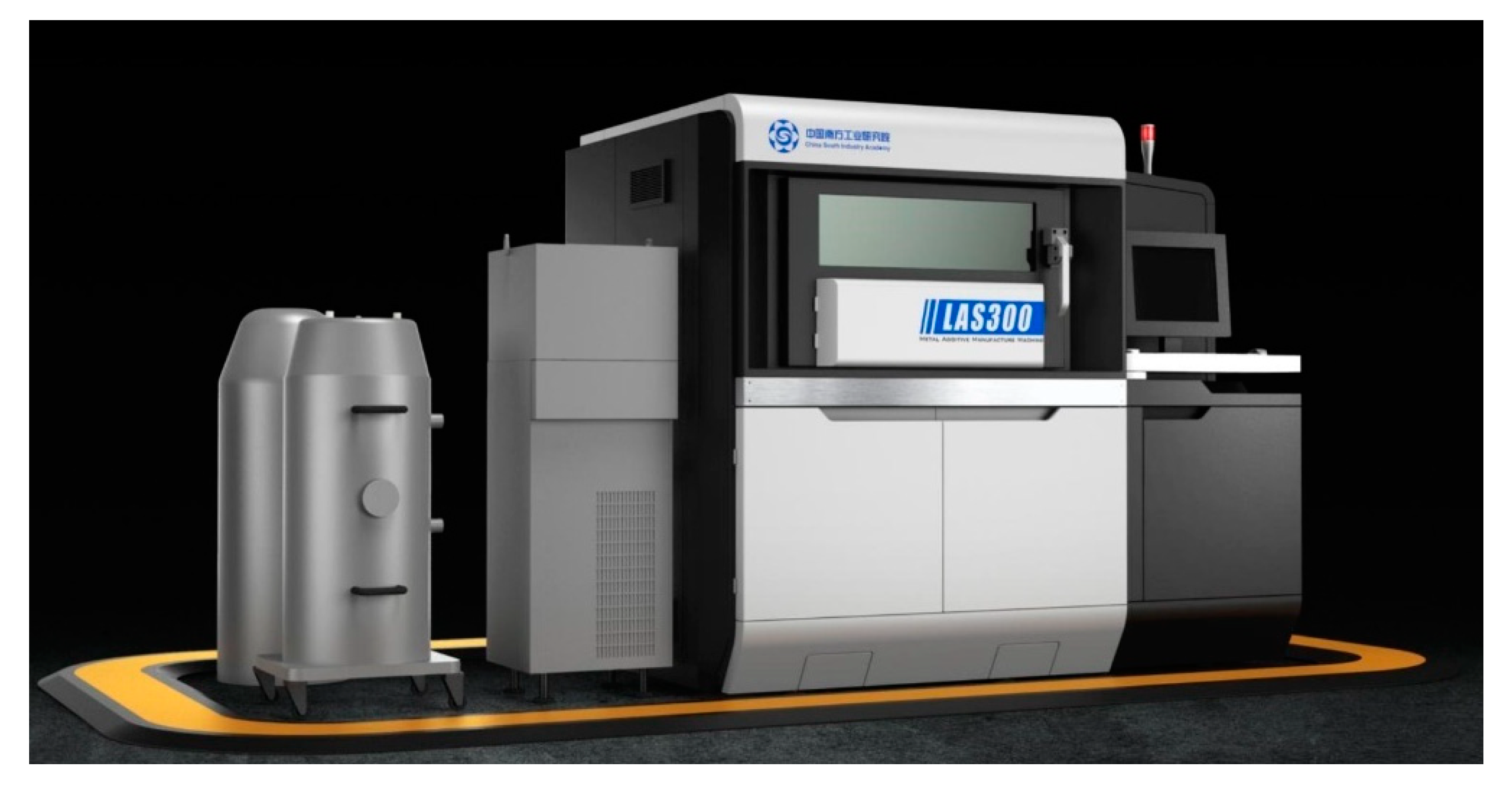
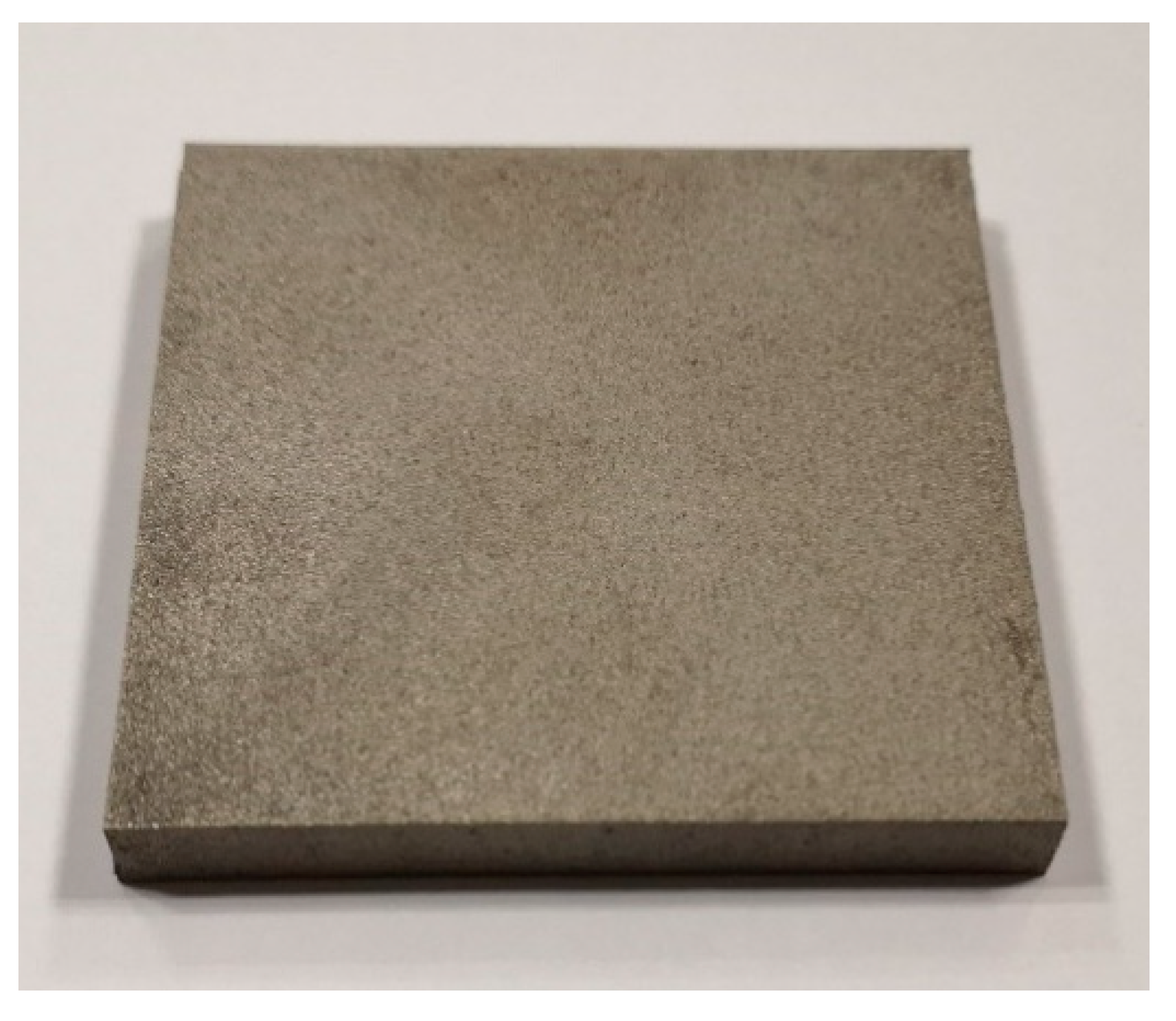
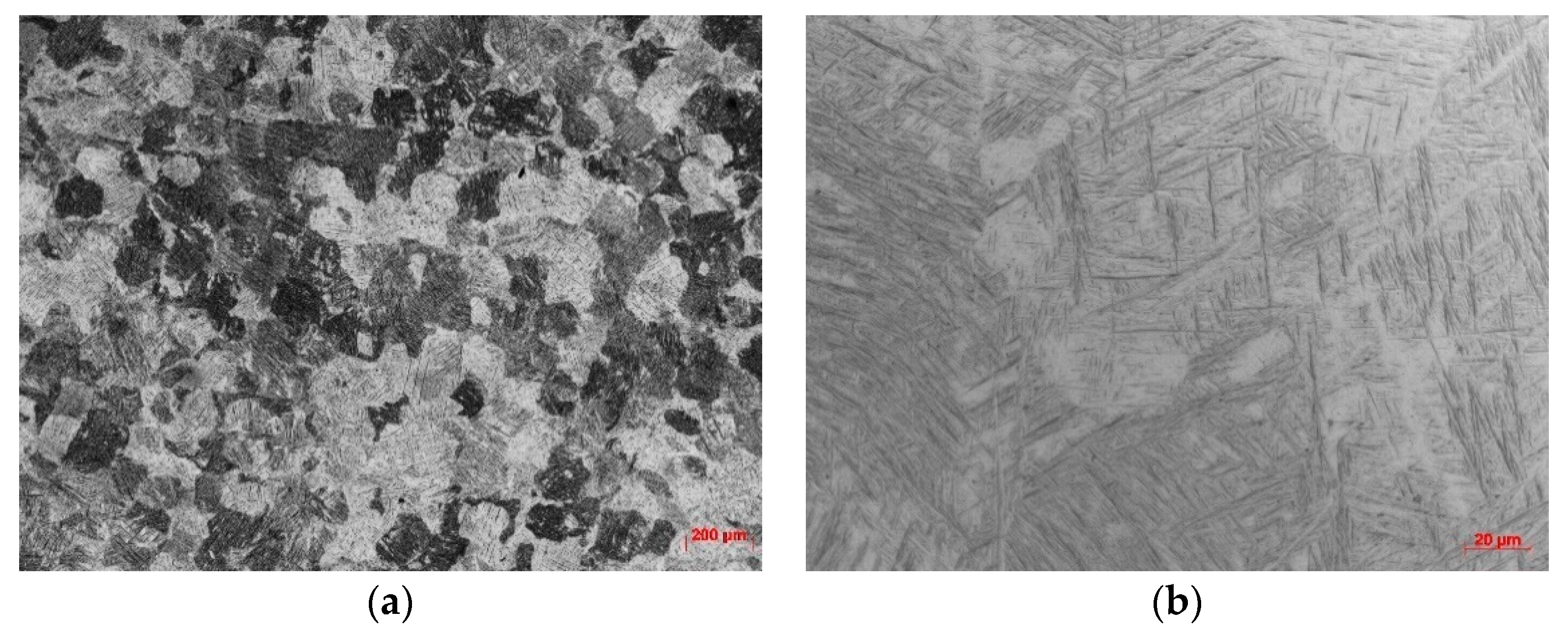
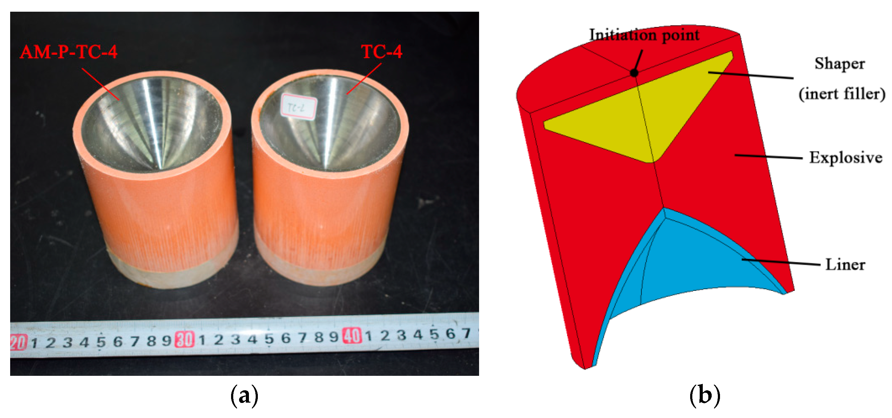
2.1. Materials
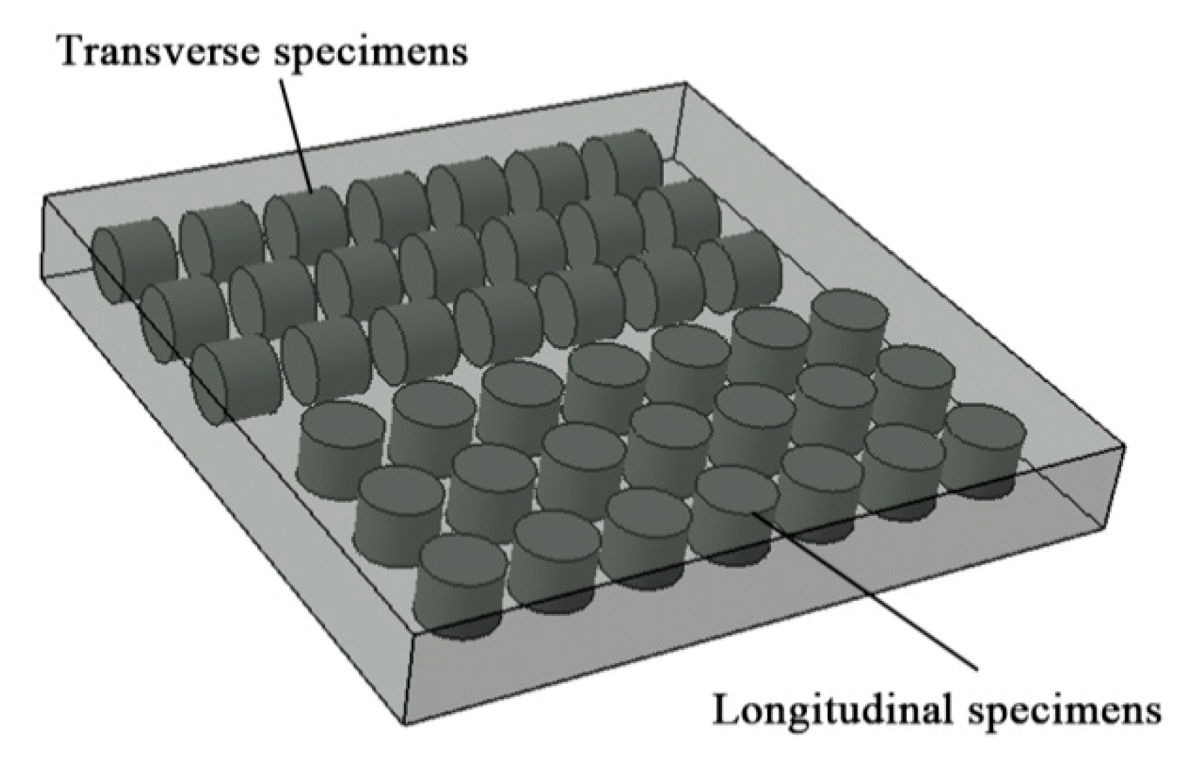
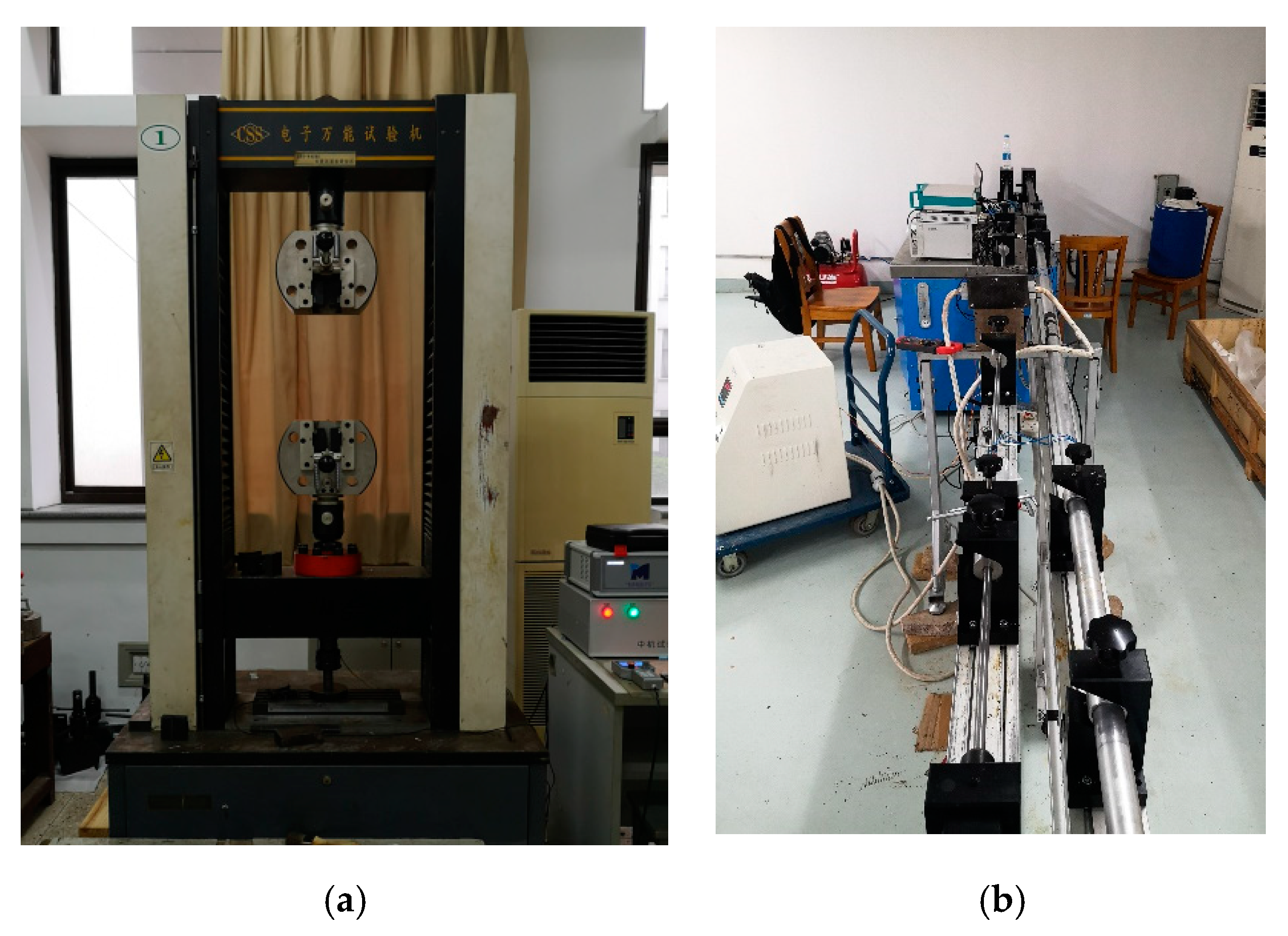
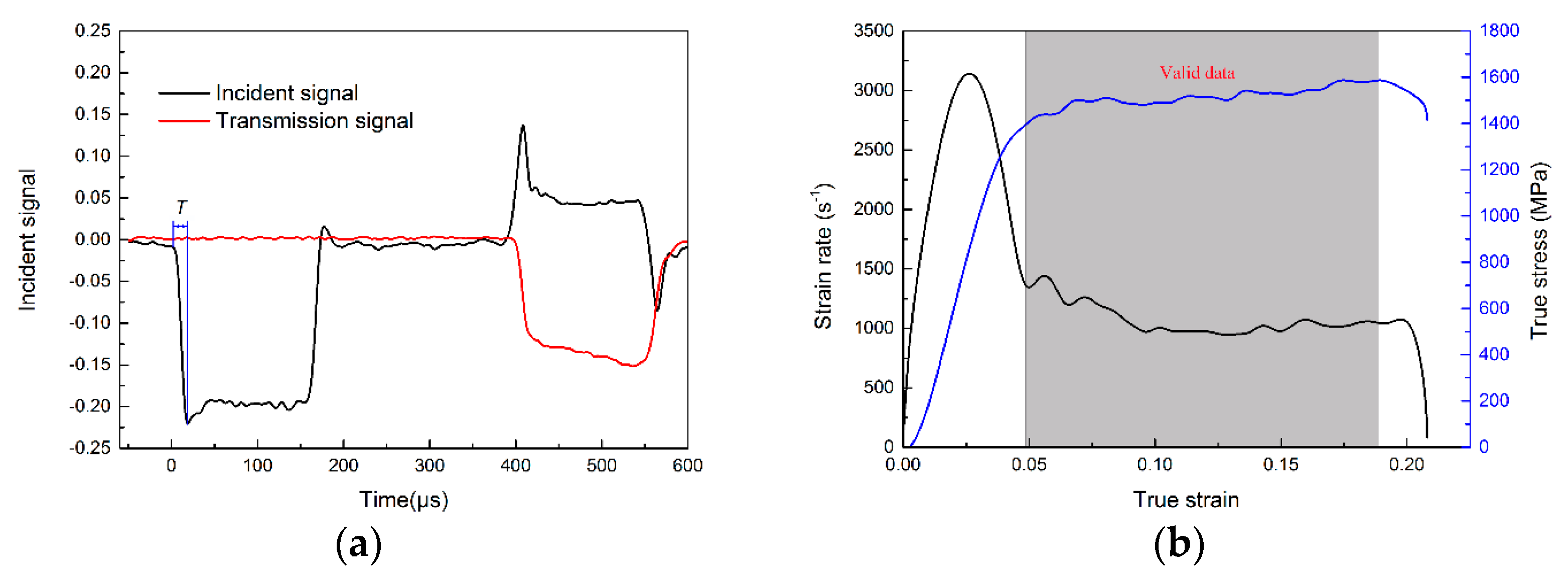
2.2. Test Method
3. Test Results and Discussion
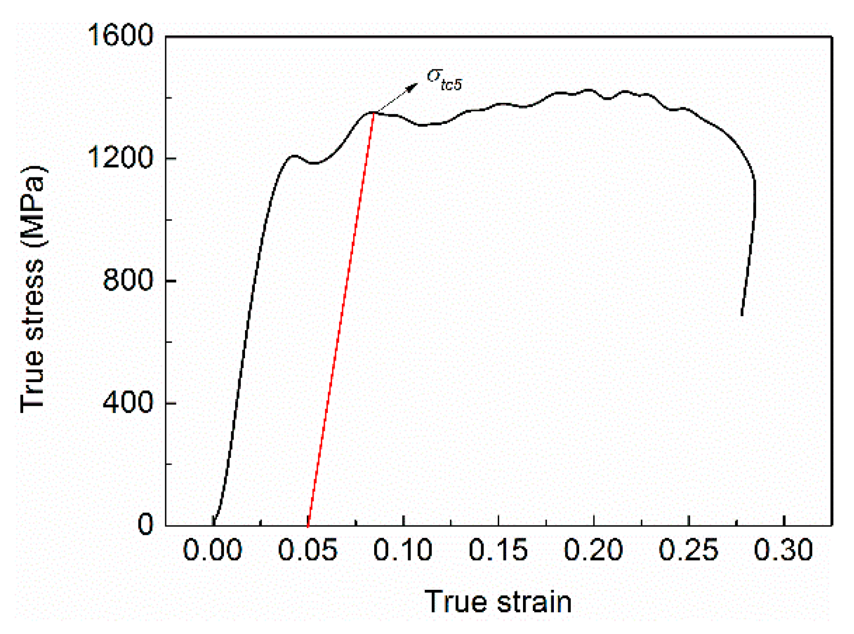
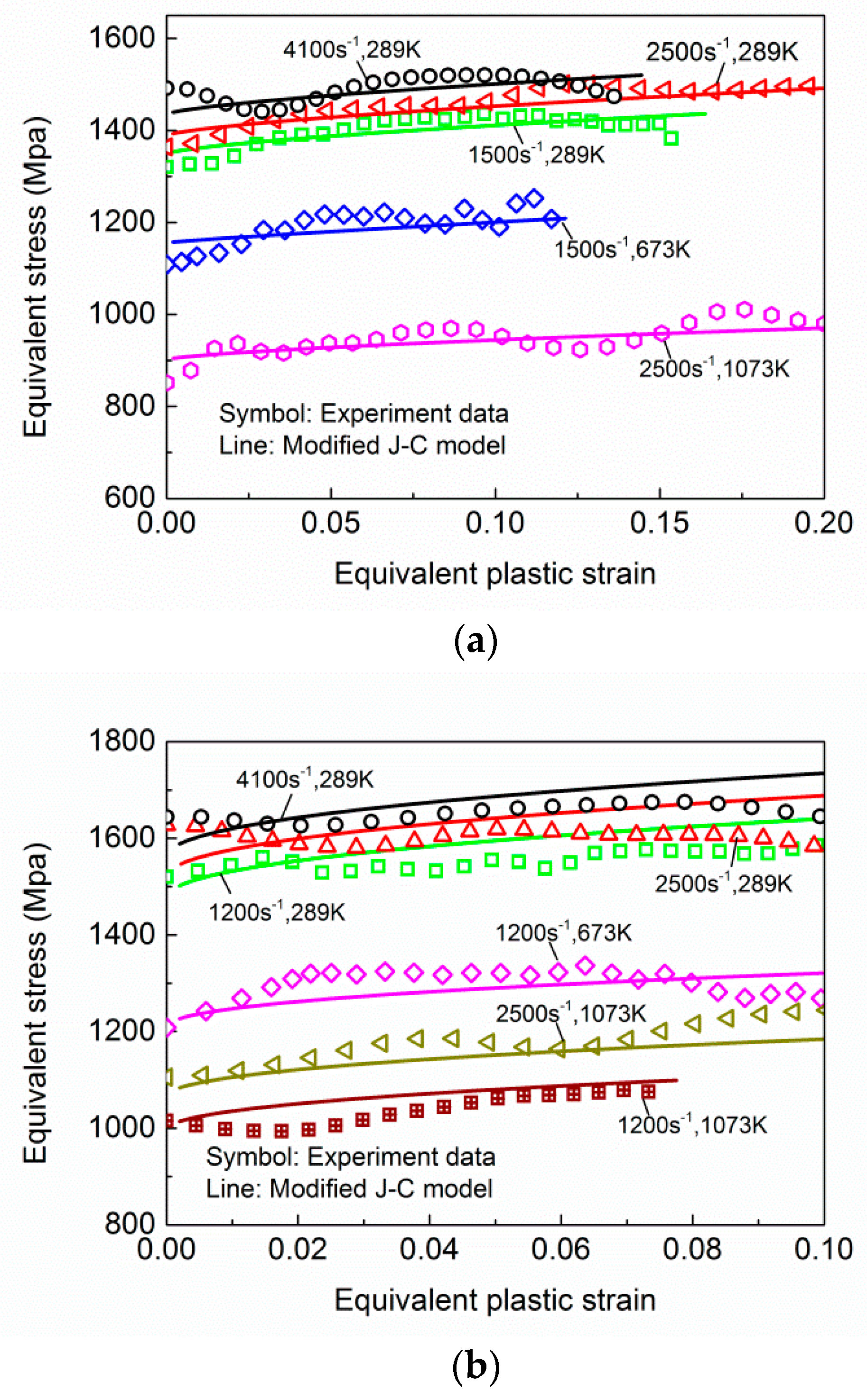
3.1. Stress–Strain Relationship
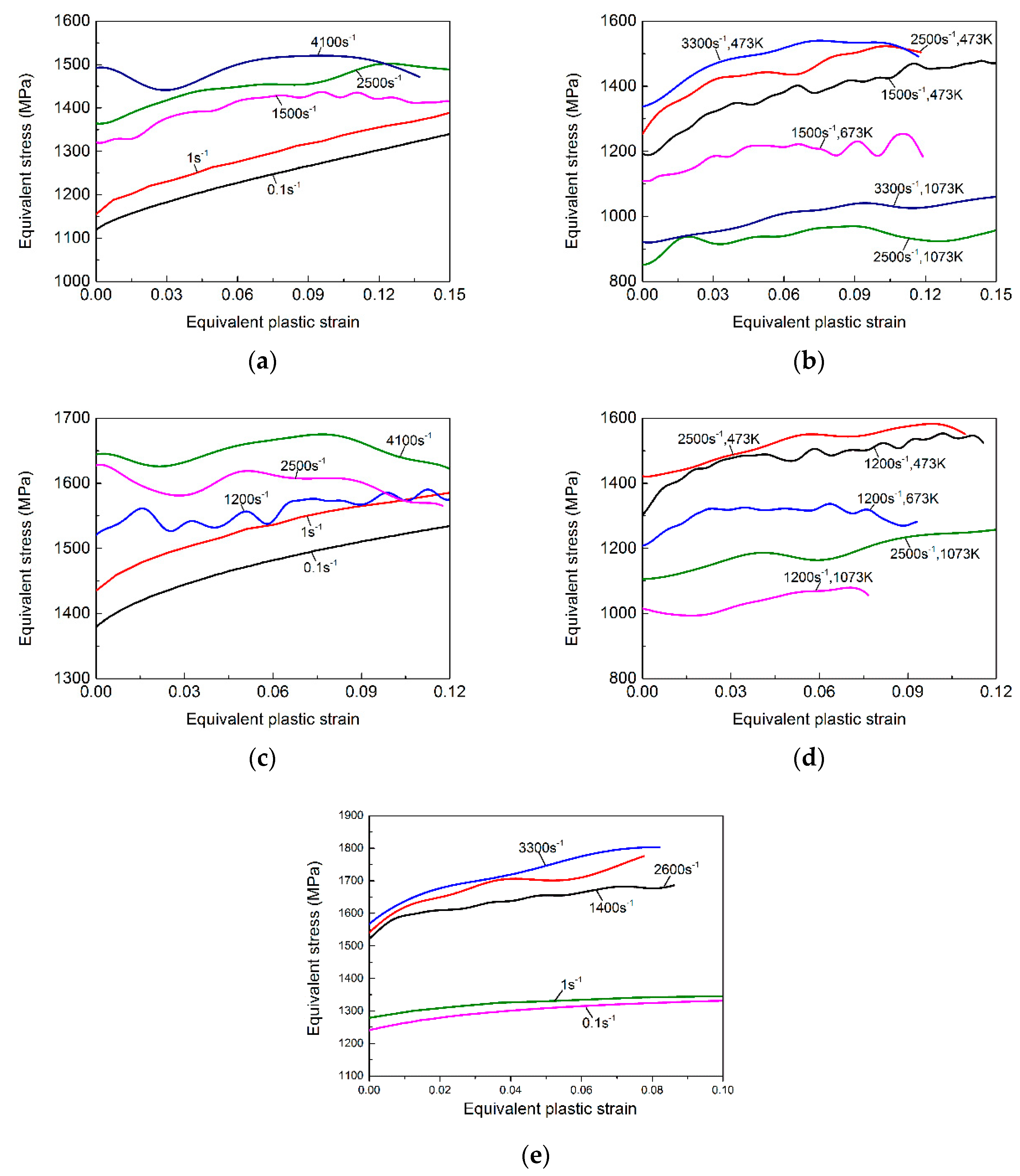
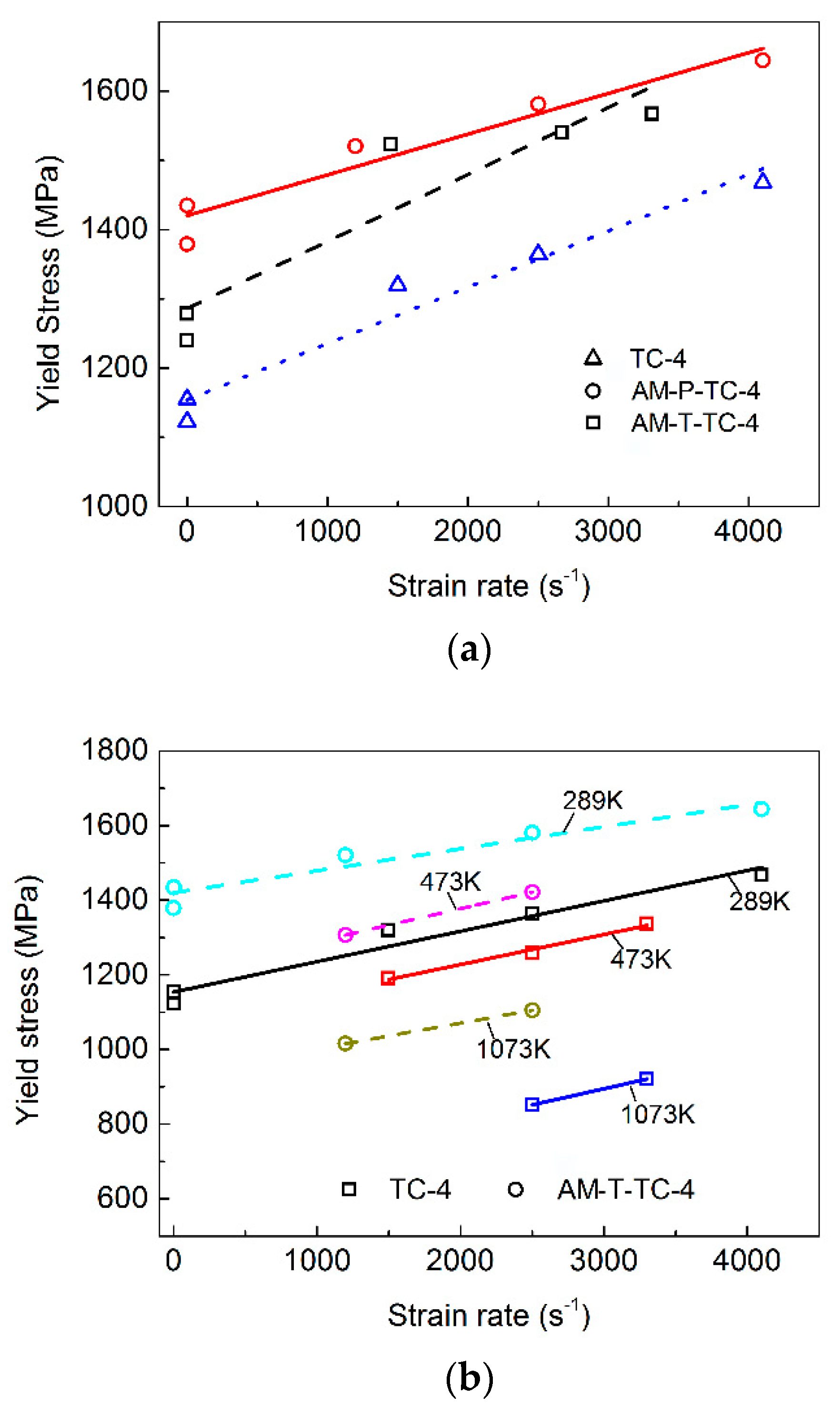
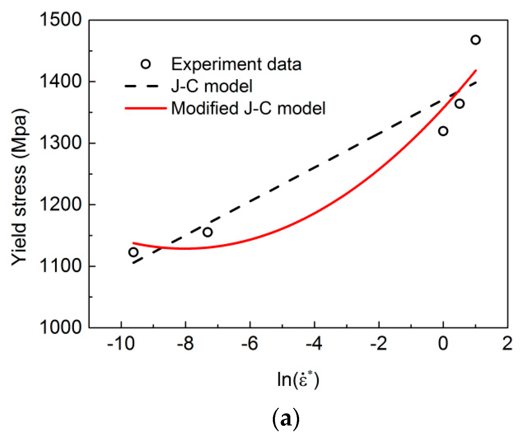
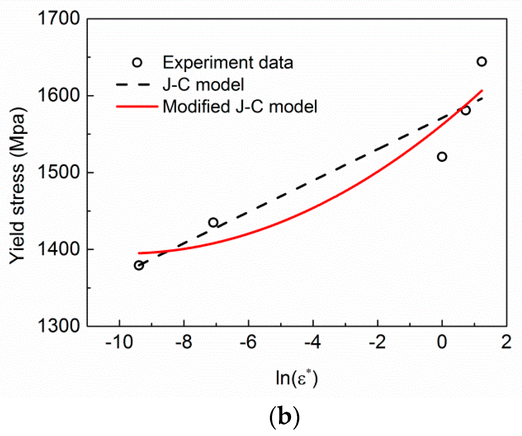
3.2. Effect of Strain Rate on Strength
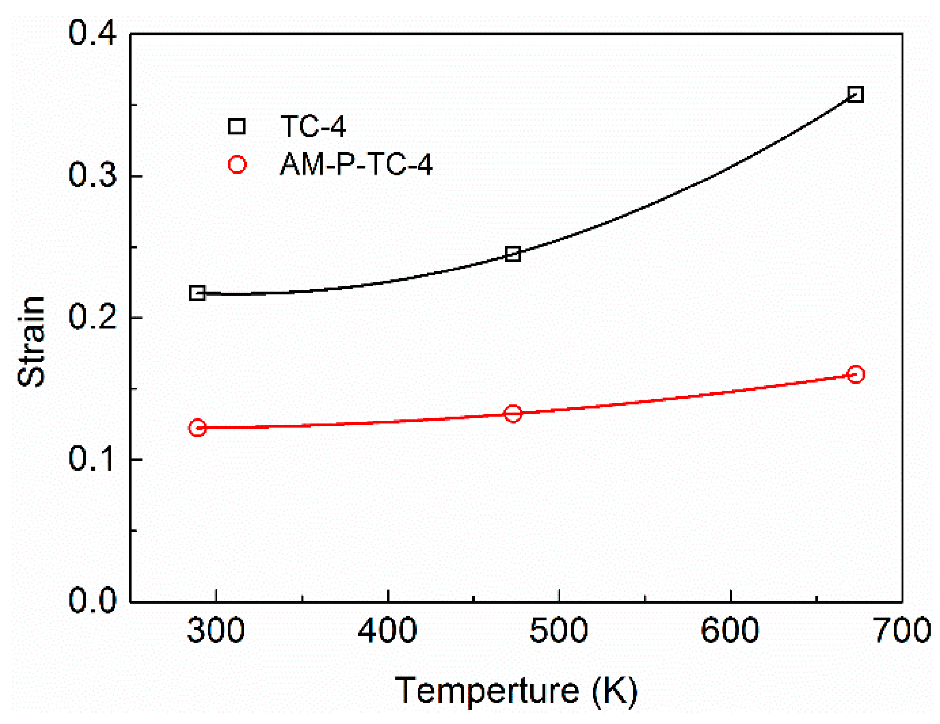
3.3. Effect of Temperature on Strength
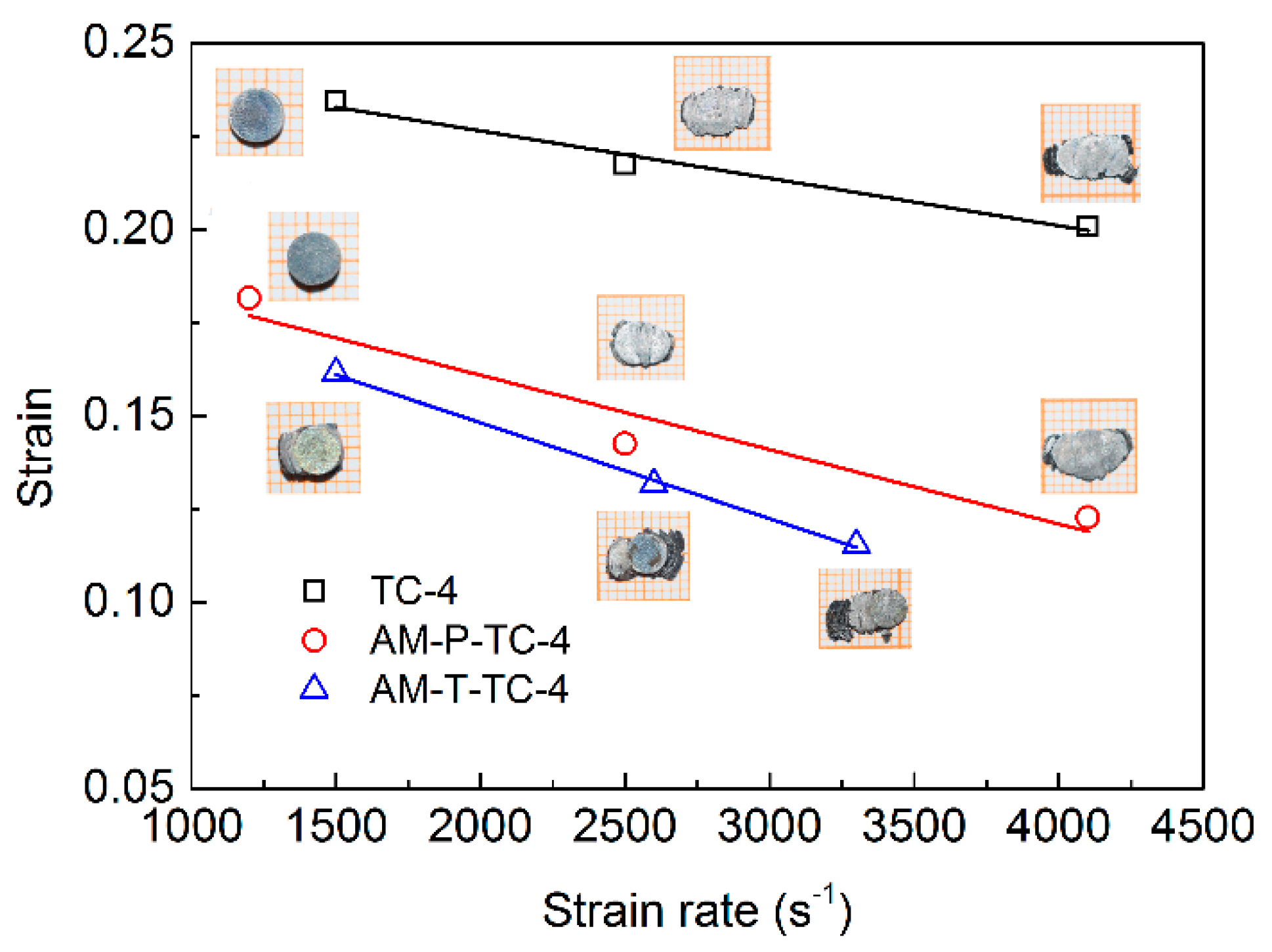
3.4. Fracture Behavior
3.5. Constitutive Relations
3.6. Plastic Deformation Behavior under Extreme Conditions
4. Conclusions
- The TC-4 alloy prepared via 3D printing had higher strength than the traditional TC-4 alloy. However, the 3D-printed TC-4 alloy was more prone to adiabatic shear fracture under dynamic compressive deformation conditions.
- The TC-4 alloy prepared via 3D-printing technology exhibited certain differences in material properties in different printing directions. The material sampled longitudinally along the printing direction under static conditions had higher strength than the material sampled transversely, but the difference was smaller under dynamic deformation conditions.
- The established modified J-C constitutive model could effectively describe the stress–strain relationship of the AM-P-TC-4 material under dynamic compressive deformation.
Author Contributions
Funding
Data Availability Statement
Conflicts of Interest
References
- Brewer, W.D.; Bird, R.K.; Wallace, T.A. Titanium alloys and processing for high speed aircraft. Mater. Sci. Eng. A Struct. 1998, A243, 299–304. [Google Scholar] [CrossRef] [Green Version]
- Poondla, N.; Srivatsan, T.; Patnaik, A.; Petraroli, M. A study of the microstructure and hardness of two titanium alloys: Commercially pure and Ti–6Al–4V. J. Alloys Compd. 2009, 486, 162–167. [Google Scholar] [CrossRef]
- Ngo, D.T.; Kashani, A.; Imbalzano, G.; Nguyen, K.T.Q.; Hui, D. Additive manufacturing (3D printing): A review of materials, methods, applications and challenges. Compos. Part B 2018, 143, 172–196. [Google Scholar] [CrossRef]
- Kotkunde, N.; Deole, A.D.; Gupta, A.K.; Singh, S.K. Comparative study of constitutive modeling for Ti–6Al–4V alloy at low strain rates and elevated temperatures. Mater. Des. 2014, 55, 999–1005. [Google Scholar] [CrossRef]
- Sun, J.; Guo, Y.B. Material flow stress and failure in multiscale machining titanium alloy Ti-6Al-4V. Int. J. Adv. Manuf. Technol. 2008, 41, 651–659. [Google Scholar] [CrossRef]
- Sima, M.; Özel, T. Modified material constitutive models for serrated chip formation Simulations and experimental validation in machining of titanium alloy Ti–6Al–4V. Int. J. Mach. Tools Manuf. 2010, 55, 943–960. [Google Scholar] [CrossRef]
- Lee, W.-S.; Lin, C.-F. Plastic deformation and fracture behaviour of Ti–6Al–4V alloy loaded with high strain rate under various temperatures. Mater. Sci. Eng. A 1998, 241, 48–59. [Google Scholar] [CrossRef]
- Song, P.; Li, W.B.; Zheng, Y.; Guan, Z.W.; Wang, X.M.; Xu, W.X.; Ge, P. The constitutive behavior of Ti-5Al-3V-2Cr-2Fe under high-velocity impact: Experimental, modeling, and validation. J. Alloys Compd. 2019, 811, 1–12. [Google Scholar] [CrossRef]
- Sterling, A.; Shamsaei, N.; Torries, B.; Thompson, S.M. Fatigue behavior of additively manufactured TC4. Procedia Eng. 2015, 133, 576–589. [Google Scholar] [CrossRef] [Green Version]
- Galarrag, H.; Warren, R.J.; Lados, D.A.; Dehoff, R.R.; Kirka, M.M.; Nandwana, P. Effects of heat treatments on microstructure and properties of TC4 ELI alloy fabricated by electron beam melting (EBM). Mater. Sci. Eng. A Struct. 2017, 685, 417–428. [Google Scholar] [CrossRef] [Green Version]
- Li, W.; Liou, F.; Newkirk, J.; Taminger, K.M.B.; Seufzer, W.J. Ti6Al4V/SS316 multi-metallic structure fabricated by laser 3D printing and thermodynamic modeling prediction. Int. J. Adv. Manuf. Technol. 2017, 92, 4511–4523. [Google Scholar] [CrossRef]
- Refael, F.; Daniel, R.; Amnon, S. Dynamic Mechanical Behavior of Additively Manufactured Ti6AI4V with Controlled Voids. J. Appl. Mech. 2015, 82, 041004. [Google Scholar]
- Dutta, B.; Froes, F.H. The additive manufacturing (AM) of titanium alloys. Titan. Powder Metall. 2015, 447–468. [Google Scholar] [CrossRef]
- Fadida, R.; Shirizly, A.; Rittel, D. Dynamic Tensile Response of Additively Manufactured Ti6Al4V with Embedded Spherical Pores. J. Appl. Mech. 2018, 85, 041004. [Google Scholar] [CrossRef]
- Fiaz, H.S.; Settle, C.R.; Hoshin, K. Metal additive manufacturing for microelectromechanical systems: Titanium alloy (Ti-6Al-4V)-based nanopositioning flexure fabricated by electron beam melting. Sens. Actuators A Phys. 2016, 249, 284–293. [Google Scholar] [CrossRef]
- Xiao, L.; Song, W.; Wang, C.; Liu, H.; Tang, H.; Wang, J. Mechanical behavior of open-cell rhombic dodecahedron Ti–6Al–4V lattice structure. Mater. Sci. Eng. A Struct. 2015, 640, 375–384. [Google Scholar] [CrossRef]
- Xiao, L.; Song, W.; Wang, C.; Tang, H.; Liu, N.; Wang, J. Yield behavior of open-cell rhombic dodecahedron Ti-6Al-4V lattice at elevated temperatures. Int. J. Mech. Sci. 2016, 115–116, 310–317. [Google Scholar] [CrossRef]
- Xiao, L.; Song, W.; Wang, C.; Tang, H.; Fan, Q.; Liu, N.; Wang, J. Mechanical properties of open-cell rhombic dodecahedron titanium alloy lattice structure manufactured using electron beam melting under dynamic loading. Int. J. Impact Eng. 2017, 100, 75–89. [Google Scholar] [CrossRef]
- Nemat-Nasser, S.; Isaacs, J.B.; Starrett, J.E. Hopkinson techniques for dynamic recovery experiments. Proc. R. Soc. Lond. A 1991, 435, 371–391. [Google Scholar]
- Zhang, X.-M.; Li, H.-J.; Li, H.-Z.; Gao, H.; Gao, Z.-G.; Liu, Y.; Liu, B. Dynamic property evaluation of aluminum alloy 2519A by split Hopkinson pressure bar. Trans. Nonferrous Met. Soc. China 2008, 18, 1–5. [Google Scholar] [CrossRef]
- Lee, W.-S.; Tang, Z.-C. Relationship between mechanical properties and microstructural response of 6061-T6 aluminum alloy impacted at elevated temperatures. Mater. Des. 2014, 58, 116–124. [Google Scholar] [CrossRef]
- Qiang, L.; Yongbo, X.; Bassim, M.N. Dynamic mechanical properties in relation to adiabatic shear band formation in titanium alloy-Ti17. Mater. Sci. Eng. A Struct. 2003, 358, 128–133. [Google Scholar] [CrossRef]
- Liu, J.; Fan, Q.; Cai, H.; Wang, F. Underlying mechanism of periodical adiabatic shear bands generated in Ti–6Al–4V target by projectile impact. Mater. Des. 2015, 87, 231–237. [Google Scholar] [CrossRef]
- Me-Bar, Y.; Rosenberg, Z. On the correlation between the ballistic behavior and dynamic properties of titanium-alloy plates. Int. J. Impact Eng. 1997, 19, 311–318. [Google Scholar] [CrossRef]
- Holt, W.H.; Mock, W.; Soper, W.G.; Coffey, C.S.; Ramachandran, V.; Armstrong, R.W. Reverse-ballistic impact study of shear plug formation and displacement in Ti6Al4V alloy. J. Appl. Phys. 1993, 73, 3753–3759. [Google Scholar] [CrossRef]
- Johnson, G.R.; Cook, W.H. A Constitutive Model and Data for Metals Subjected to Large Strains, High Strain Rates and High Temperatures. In Proceedings of the 7th International Symposium on Ballistic, The Hague, The Netherlands, 19–21 April 1983; pp. 541–547. [Google Scholar]
- Huh, H.; Kang, W.J.; Han, S.S. A Tension Split Hopkinson Bar for Investigating the Dynamic Behavior of Sheet Metals. Exp. Mech. 2002, 42, 8–17. [Google Scholar] [CrossRef]
- Rajeev, K.; Sia, N.N. Determination of temperature rise during high strain rate deformation. Mech. Mater. 1998, 24, 1–12. [Google Scholar]
- Song, P.; Li, W.-B.; Zheng, Y.; Song, J.-P.; Jiang, X.-C.; Yan, B.-Y. Study on Plastic Deformation Behavior of Mo-10Ta under Ultra-High Strain Rate. Metals 2020, 10, 1153. [Google Scholar] [CrossRef]


| Material | Composition (wt.%) | ||||
|---|---|---|---|---|---|
| Al | V | O | Fe | Ti | |
| TC-4 | 6.30 | 4.10 | <0.14 | <0.14 | Balance |
| AM-TC-4 | 6.13 | 4.00 | <0.15 | <0.25 | Balance |
| Parameter | Values |
|---|---|
| Laser Power | 340 W |
| Scan Speed | 1250 mm/s |
| Layer Thickness | 60 μm |
| Description | Notations | Values | |
|---|---|---|---|
| TC-4 | AM-P-TC-4 | ||
| Density | ρ (g/cm3) | 4.459 | 4.120 |
| Yield stress constant | A (Mpa) | 1357.2 | 1480.3 |
| Strain hardening constant | B (Mpa) | 303.15 | 480.3 |
| - | n | 0.686 | 0.465 |
| Strain rate hardening constant | C1 | 0.0519 | 0.0217 |
| Strain rate hardening constant | C2 | 0.0116 | 0.018 |
| Thermal softening constant | m | 1.17 | 1.15 |
| Reference strain rate | (s−1) | 1500 | 1200 |
| Melting temperature | Tm (K) | 2110 | 2110 |
| Reference temperature | Tr (K) | 289 | 289 |
| Liner | Time (μs) | Jet Pattern |
|---|---|---|
| TC-4 | 40 |  |
| 60 |  | |
| AM-P-TC-4 | 40 |  |
| 60 |  |
Publisher’s Note: MDPI stays neutral with regard to jurisdictional claims in published maps and institutional affiliations. |
© 2021 by the authors. Licensee MDPI, Basel, Switzerland. This article is an open access article distributed under the terms and conditions of the Creative Commons Attribution (CC BY) license (https://creativecommons.org/licenses/by/4.0/).
Share and Cite
Pu, B.; Li, W.; Zhang, Q.; Zheng, Y.; Wang, X. Research on the Dynamic Compressive Deformation Behavior of 3D-Printed Ti6Al4V. Metals 2021, 11, 1327. https://doi.org/10.3390/met11081327
Pu B, Li W, Zhang Q, Zheng Y, Wang X. Research on the Dynamic Compressive Deformation Behavior of 3D-Printed Ti6Al4V. Metals. 2021; 11(8):1327. https://doi.org/10.3390/met11081327
Chicago/Turabian StylePu, Bo, Wenbin Li, Qing Zhang, Yu Zheng, and Xiaoming Wang. 2021. "Research on the Dynamic Compressive Deformation Behavior of 3D-Printed Ti6Al4V" Metals 11, no. 8: 1327. https://doi.org/10.3390/met11081327