Review

Analysis of Hydrogen Embrittlement on Aluminum Alloys for Vehicle-Mounted Hydrogen Storage Tanks: A Review

1
Hubei Key Laboratory of Advanced Technology for Automotive Components, Wuhan University of Technology, Wuhan 430070, China
2
Hubei Collaborative Innovation Center for Automotive Components Technology, Wuhan 430070, China
3
Hubei Engineering Research Center for Green & Precision Material Forming, Wuhan 430070, China
*
Authors to whom correspondence should be addressed.
Metals 2021, 11(8), 1303; https://doi.org/10.3390/met11081303
Submission received: 18 June 2021 / Revised: 10 August 2021 / Accepted: 10 August 2021 / Published: 17 August 2021
(This article belongs to the Special Issue Forming of Aluminium Alloys)

Abstract

:
High-pressure hydrogen tanks which are composed of an aluminum alloy liner and a carbon fiber wound layer are currently the most popular means to store hydrogen on vehicles. Nevertheless, the aluminum alloy is easily affected by high-pressure hydrogen, which leads to the appearance of hydrogen embrittlement (HE). Serious HE of hydrogen tank represents a huge dangers to the safety of vehicles and passengers. It is critical and timely to outline the mainstream approach and point out potential avenues for further investigation of HE. An analysis, including the mechanism (including hydrogen-enhanced local plasticity model, hydrogen-enhanced decohesion mechanism and hydrogen pressure theory), the detection (including slow strain rate test, linearly increasing stress test and so on) and methods for the prevention of HE on aluminum alloys of hydrogen vehicles (such as coating) are systematically presented in this work. Moreover, the entire experimental detection procedures for HE are expounded. Ultimately, the prevention measures are discussed in detail. It is believed that further prevention measures will rely on the integration of multiple prevention methods. Successfully solving this problem is of great significance to reduce the risk of failure of hydrogen storage tanks and improve the reliability of aluminum alloys for engineering applications in various industries including automotive and aerospace.

1. Introduction

More and more attention has been paid to the safety of transportation equipment [1,2,3]. Facing the energy crisis, hydrogen-fueled vehicles are recognized as a most promising solution [4,5,6,7]. Compared with electric vehicles, when refueling with energy, the hydrogen vehicle has advantages of technical simplicity and high filling rates [8]. The main steps and milestones in the development of hydrogen vehicle are shown in Figure 1.
However, because of the hazardous properties high-pressure hydrogen such as high diffusivity and low ignition energy, it tends to spontaneously ignite during sudden release [9]. For the hydrogen vehicle, the hydrogen storage ability is an important factor that affects its safety and performance. Compared with other methods, high-pressure hydrogen storage has advantages in terms of hydrogen storage density, economy and being closer to practical applications [10]. The hydrogen storage container is the key component of the hydrogen vehicle [11]. At present, the most widely used hydrogen storage container is the III-type composite hydrogen storage tank whose inner liner is made of aluminum [12].
It is widely accepted that hydrogen embrittlement (HE) has become a serious problem since high-strength steel became widely used [5,7,13,14]. With the widespread application of aluminum alloys, it’s found that aluminum and its alloys also have a higher hydrogen content [15,16,17]. However, due to the wide application of aluminum alloys, when hydrogen embrittlement causes the failure of aluminum alloys, catastrophic accidents can occur. In order to alleviate these conditions, hydrogen embrittlement must be paid enough attention [18]. It affects the service safety of aluminum alloys in the automotive, hydrogen energy, aerospace, petrochemicals, and other industrial fields [19]. Through the sorting and reading of the references, we concluded that the main cause of aluminum alloy failure is fractures, and HE will lead to the fracture of aluminum alloys. Finding effective protection methods to prevent hydrogen embrittlement is an urgent matter [20]. Aluminum alloys with low mass and reasonable mechanical properties are considered as promising alloys for structural materials in aerospace systems and vehicle products [21,22]. The research direction of fuel cells and hydrogen energy safety includes three themes: hydrogen energy supply, fuel storage tank design and hydrogen leakage [23]. According to the related study, the dotted circle as shown in the Figure 2 is the key part of the hydrogen storage bottle when being produced. There may be micro cracks between the bottle cap and the weld [24], which will make hydrogen embrittlement more likely to occur [25].
In the process of HE, there is no obvious signature of failure of material components [26,27,28]. In recent years, many scholars have conducted failure studies on hydrogen storage bottles with aluminum alloy inner tanks and explored their microscopic failure mechanisms. It is obvious that HE is a phenomenon that cannot be ignored. The importance of improving or solving the problem of HE is self-evident for hydrogen storage tanks [12,29,30,31]. The working principle of a typical hydrogen storage tank is shown in Figure 3.
Due to the wide application of aluminum alloys, they are not only used in hydrogen vehicles to store liquid hydrogen, but also in the military industry and aerospace industry [16,32]. Apart from this, due to the wide sources of hydrogen, and under certain circumstances (such as the presence of chloride or humid air) that hydrogen itself does not necessarily exist, numerous conditions may cause hydrogen to enter the aluminum alloys [33].
The HE of aluminum alloy has become an important factor restricting its application and development [34]. Since the 1980s, the problem of HE has been a concern and studied by many scholars, based on which many theories have been proposed [35] to explain HE, such as the hydrogen-enhanced decohesion mechanism (HEDE) and the hydrogen-enhanced local plasticity model (HELP).
Nowadays, there has been some research on HE which leads to the failure of hydrogen storage bottles. However, a systematic sorting has not been done. The relevant literature related to HE, especially the progress in the past three years have been reviewed in this paper, which is conducive to the further study of hydrogen embrittlement by interested scholars. The safety analysis, including the formation mechanism, the detection technology and the prevention methods of hydrogen embrittlement (HE) in aluminum alloys are comprehensively summarized in this work, which will help to improve the storage safety of hydrogen fuel for several industries, including automotive and aerospace. Also, solving the problem of HE is of great significance to improve the effectiveness and reliability of aluminum alloys. When getting used in the hydrogen energy, petrochemicals, and other industrial fields, it is also helpful to reduce the occurrence of major disasters caused by HE.

2. Mechanism of Hydrogen Embrittlement

To effectively prevent HE and ensure safety, it is necessary to fully understand the mechanisms of HE. In industry, when aluminum is used, many catastrophic consequences are caused by HE. The development of aluminum alloys is greatly limited. After the 1980s, HE has gradually attracted the attention of scholars. The crack initiation and propagation will lead to the failure of aluminum alloys. In order to explain the specific causes of HE, studies were carried out on many aspects of the problem. It was found that there were many mechanisms that can lead to HE of materials. Based on that, during the last 50 years, many theories have been proposed, including HELP, HEDE, AIDE, HEMP and DHF. The three most widely accepted mechanisms are explained in detail in this work. HE of alloy materials may also be caused by the combination of various mechanisms. Due to the differences between aluminum alloys and steel, titanium and other metals, the actual mechanism which causes embrittlement occurs in aluminum alloys is unclear. The research to identify the main embrittlement causes of the aluminum alloys is ongoing. The major mechanisms are discussed in detail below.

2.1. Hydrogen Enhanced Local Plasticity Model (HELP)

The hydrogen-enhanced local plasticity model (HELP) was first put forward in 1972 and is widely accepted. HELP states that under constant load conditions, hydrogen atoms will undergo stress-induced diffusion and continue to be enriched towards the tip of the crack. When reaching a critical value, this will lead to the formation of hydrogen-induced cracks, which will make fractures appear in the material [36].
Based on this, Verners et al. [34] studied aluminum with a face-centered cubic structure. They found that the hydrogen diffusivity has a strong dependence on the microstructure. The concentration of hydrogen can be increased by the existence of dislocations, which in turn leads to HE. Apart from that, according to Lynch’s research results, it also shown that the HE mechanism of face-centered cubic structured materials was likely to be HELP [37]. Gupta et al. [31] used synchrotron microtomography to observe a 7075 aluminum alloy sample after hydrogen charging. This showed that the deformation caused the redistribution of hydrogen, forming an expansion and accumulation zone near the intergranular crack. The agglomerated damaged area was proved to be a mechanical result, which caused intergranular damage due to its easy trapping of hydrogen. However, it did not show whether the agglomeration zone was formed before the intergranular cracks developed. The causal relationship between the agglomeration zone and the crack development could not be clarified. In all images, the alloy matrix is shown in gray. Many dark and bright objects of different shapes are embedded in these gray matrices. The bright objects in the slices are intermetallic particles (including Fe, Cu, and Al) commonly found in AA7075, while the dark objects are different types of microdamage. These dark objects were considered microdamage areas because they have obvious halos at the edges, as shown in Figure 4.
Qi et al. [32] proved that because of the presence of hydrogen, the local plastic deformation of the material will reach a critical value under a lower stress. This will lead to the nucleation and continuous development of hydrogen-induced cracks and even the material fracture.

2.2. Hydrogen Enhanced Decohesion Mechanism (HEDE)

The hydrogen-enhanced decohesion mechanism (HEDE) was first proposed by Troiano in 1959. It is the simplest one among the existing theories. Its premise is that hydrogen atoms reduce the cohesive strength of the material in the crack tip area [36]. When studying the effect of hydrogen on the properties of steel parts, Troiano proposed that the single electron in the 1s orbital of the hydrogen atom will enter the d orbital of the transition metal, which means that the repulsive force between the iron atoms will be increased. When hydrogen atoms are available all around the material and some types of stresses are acting on it then hydrogen atoms diffuse inside a material and decrease the interatomic strength or cohesive strength of a material at the crack tip and cleavage like fractures occurs [32].
In general, the theory believes that local lower stress will lead to the destruction of the bonds between atoms. At the same time, microscopic cracks will appear. Although the theory has been affirmed by many scholars, it remains at the theoretical level, without experimental proof.

2.3. Hydrogen Pressure Theory

When H in a supersaturated state is present in an aluminum alloy, it is likely to be present in the microscopic cracks of the material in the form of H2. Therefore, as the H2 concentration at the defect increases, the hydrogen pressure also increases. When the stress generated by the hydrogen pressure is greater than the yield strength of material, the surface of the aluminum alloy will swell. Bubbles will be formed. This will cause the continuous development of microscopic cracks in the aluminum and eventually cracks will appear in the aluminum.
Scholars have used TEM technology to test 7075 aluminum alloy. It is found that hydrogen not only enhanced the dislocation mobility, but was also concentrated at the cracks in the high-stress area, which promoted ductile fractures at the cracks [36]. The results of this work have proved the rationality of the hydrogen pressure theory to a certain extent.

2.4. Adsorption-Induced Dislocation Emission (AIDE)

The adsorption of hydrogen atoms on the metal surface strongly affects the surface energy. Furthermore, these hydrogens can promote or inhibit the nucleation of dislocations on the surface, which is called an adsorption-induced dislocation emission mechanism [35]. In the future research, in order to depict the crack-tip dislocation emission, two questions should be clear for researchers. One is when the dislocation can spread successfully from the crack-tip, the other is where the ‘source’ of the emitted dislocation should be located [38].

2.5. Hydrogen-Enhanced Strain-Induced Vacancy Generation (HESIV)

The interaction between hydrogen and vacancies or their clusters reduces the vacancy formation energy, thereby promoting the nucleation of the vacancy. Therefore, the increase in vacancy density promotes the formation of H-vacancy complexes and leads to an enhanced pinning effect on mobile dislocations, which is called the mechanism of hydrogen-enhanced strain-induced vacancy generation (HESIV) [39]. It mainly captures the hydrogen-enhanced generation of vacancy H complexes or vacancy-hydrogen clusters and their pinning effect on the moving edge dislocations. However, studies have shown that unless the hydrogen concentration is abnormally high, the effect of hydrogen-enhanced strain-induced vacancies (HESIV) on hydrogen-induced intergranular fracture is much weaker [38].

2.6. The Influential Factors

2.6.1. Solution Environment

It is widely accepted that, in the solution, due to the hydrolysis of aluminum ions [40,41,42]. A13+ + 3H2O = Al(OH)3 + 3H+, the pH of the solution will drop. Because the mass transfer of O2 at the crack tip is restricted, hydrogen evolution reactions can occur at the cathode formed in the crack. As a result, the hydrogen atoms will enter the crack tip. Combined with the hydrogen pressure theory mentioned above, it can be inferred that the hydrogen pressure at the crack of the material will increase at this time, making the crack grow more easily. The principle is shown in Figure 5.
The hydrogen storage tank on the vehicle normally does not involve a humid environment. Only liquid hydrogen should exist in its working environment. However, the working conditions of general aerospace aluminum alloys is mostly humid, with exposure to industrial exhaust gases and even acid rain. Therefore, it is necessary to analyze its influence on aluminum alloy fatigue strength and HE from the perspective of solutions.

2.6.2. Alloy Composition

Generally speaking, the more the total amount of alloying elements dissolved in the supersaturated solid solution, the higher its stress corrosion sensitivity will be. For ternary and above aluminum alloys, the stress corrosion sensitivity depends not only on the total amount of alloying elements, but also on the ratio of these alloying elements [43]. The presence of alloy elements will not only affect the structure of the aluminum alloy, but also affect its electrochemical properties. If new alloy elements are properly introduced into the aluminum alloy, they may interact with H. By affecting the existence and activity of H, it may have an important impact on the HE sensitivity of the material, which is of great significance for improving the properties of aluminum alloys.

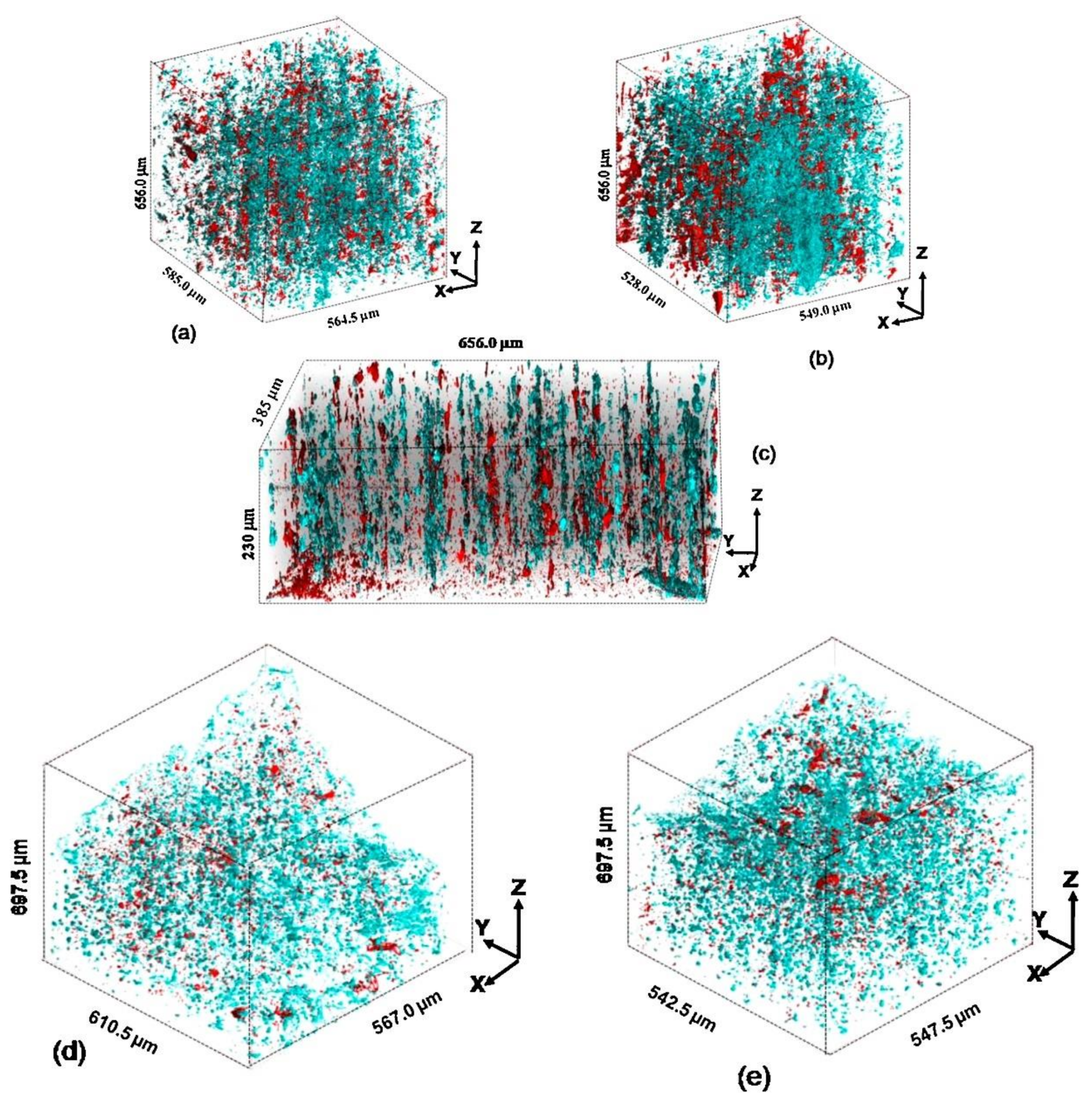
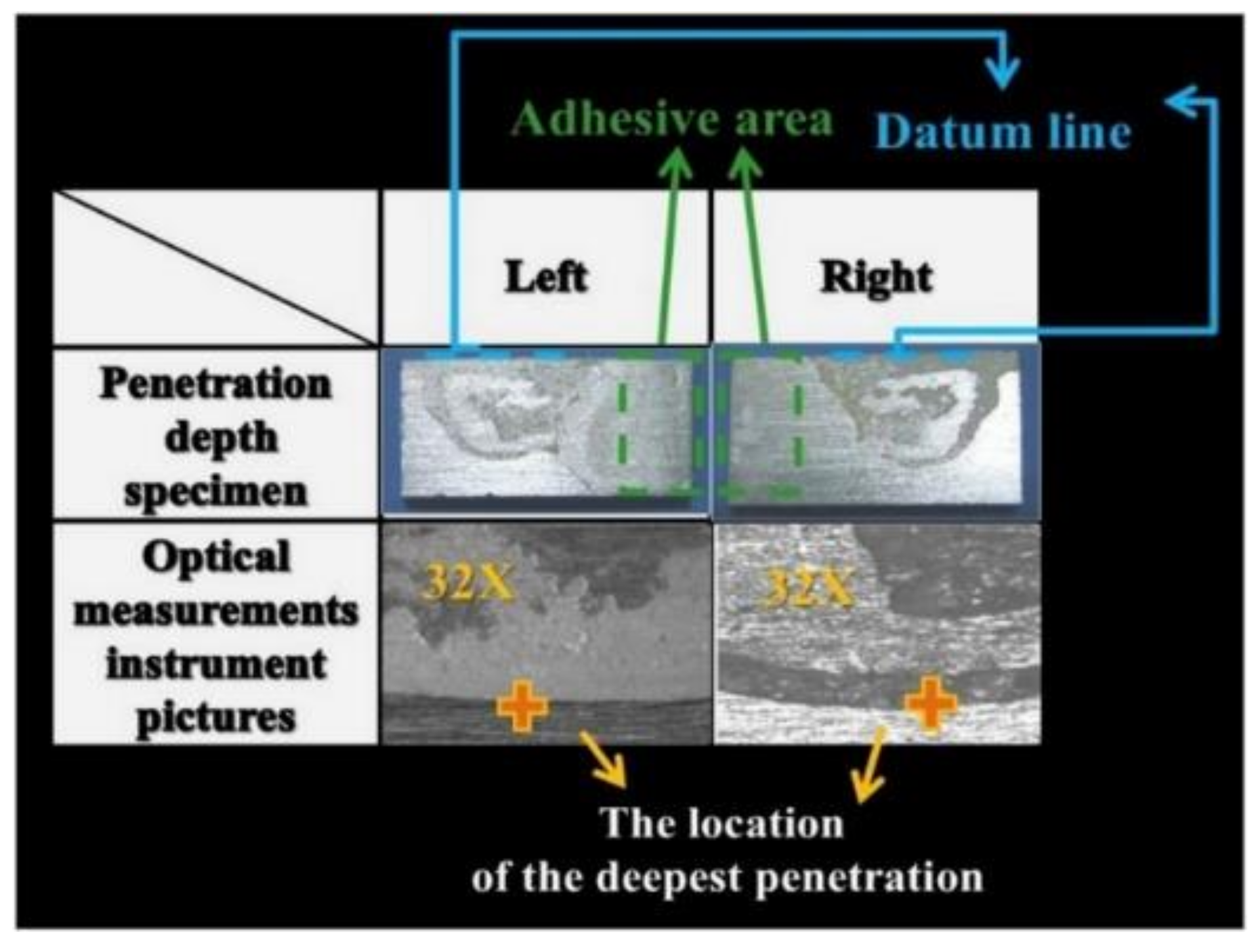
2.6.3. The Depth of Hydrogen Penetration

Panagopoulos et al. [40] pointed out that the occurrence of HE is closely related to the depth of H diffusion into the sample. If the diffusion depth is not deep enough, it will not cause HE.
From the influencing factors studied by scholars previously [44], we should proceed from the influencing factors and then formulate appropriate measures to prevent HE. For example, in terms of the structure of the material, Song et al. [43] proposed a method of heat treatment to improve the strength of aluminum alloy. It is also helpful to prevent HE. With the aging treatment at 413 K for 6 h, 16 h, 98 h, 200 h, the fracture surface pattern of the sample tested in 3.5% NaCl solution is shown in Figure 6.
Dey et al. [45] proposed some improvement schemes to limit the diffusion depth of H in the material. Many scholars have proposed that coating is also based on the depth of H diffusion in the material. Therefore, when proposing structural measures for HE, it is necessary to study the mechanism and main influencing factors of HE carefully. These methods will be introduced below.

3. Detection Methods of Hydrogen Embrittlement

There are many testing methods for the HE of materials including LIST, SSRT, the electrochemical cathode hydrogen permeation method, corrosive environment simulation tests, SEM, TEM, HMT, localized techniques and so on. Focusing on the HE of aluminum alloys, the following methods are widely used and therefore are introduced in details in this paper: SSRT, LIST, SEM, TEM.

3.1. Methods to Prepare the Material

3.1.1. Electrochemical Cathode Hydrogen Permeation Method

To detect and analyze HE in materials, it is necessary to select a suitable method to cause HE first. When studying HE, Gupta et al. [31] heat-treated the material by a solutioning step at 520 °C for 144 h, followed by aging at 120 °C for 8 h in an oil bath. In this process, it transformed the flat pancake grain structure found in the hot extruded rods of AA7075 into an equiaxed microstructure with average grain size of about 80 μm. The studies were carried out on under-age AA7075. The condition is known to make the alloy most susceptible to HE.
In electrochemical cathode hydrogen permeation, a fine platinum wire mesh is used as the anode. The 7075 aluminum alloy sample is used as the cathode. The electrolyte composition is Na2HAsO4·7H2O, and a trace of As2O3 is added as a poisoning agent [46]. This can make it more difficult for hydrogen atoms to combine, which will help increase the concentration of hydrogen atoms on the surface of the sample. Among many preparation and research methods, this method is considered as a common one. The authors believe that it has certain feasibility. When processing materials, the main idea of such a treatment is to convert them into the equiaxed microstructures which are the form most susceptible to HE.

3.1.2. Corrosive Environment Simulation Test

Aluminum alloy products are mostly exposed to corrosive environments when in use. It is necessary to test aluminum alloys in corrosive environments [47]. Petroyiannis et al. [47] proposed a new experimental method when studying 2024 series and 6013 series aluminum alloys. A sample is shown in Figure 7.
The aluminum alloy material is made into a thin plate with a thickness of 1.6 mm, and a tensile specimen is prepared on this basis. Tensile specimens are processed in accordance with ASTM E8m-94a [48] standards. The specimens need to be cut along the longitudinal (L) and transversal directions. When cutting the fracture toughness specimens in the (L) direction, the ASTM E561-94 [49] standards should be followed. Finally, according to the ASTM G34-90 [50] should be followed, the tensile samples were exposed to a peeling corrosion environment. The corrosive environment is simulated by a solution with a volume of 1 L, containing sodium chloride (4.0 M NaCl, potassium nitrate (0.5 M KNO3) and nitric acid (0.1 M HNO3). The initial pH of the solution is 0.4. Temperature of the solution during the control experiment is 25 ± 3 °C. The sample should be exposed to the solution for different exposure times. After exposure, the sample is cleaned in accordance with ASTM G34-90 [50]. Then the corroded sample is tested test to observe the surface corrosion and measure its yield stress, ultimate stress, strain energy density, etc. [47].
The author reckons that, among the material processing methods, there is no method that simulates an environment where high pressure, airtight, and liquid hydrogen exist. There is no proposal for the hydrogen storage tank with aluminum alloy inner liner. The study of the HE characteristics of aluminum alloy hydrogen storage tanks and proposals of corresponding measures to prevent HE are still awaiting in-depth research in this area and the proposal of related experimental programs.

3.2. Tensile Test Method

3.2.1. Slow Strain Rate Test (SSRT)

Slow strain rate tests are a fast test method for measuring stress corrosion cracking performance. A sample is slowly and uniformly stretched on a constant strain rate machine until it breaks. It is a kind of method where as time is going by, the stretch rate of the material is increasing, until the sample breaks [16]. The appearance of the sample is shown in Figure 8.
According to the ASTM G129 [51] standard, sensitivity to HE can be expressed by reducing the area ratio (RRA) and reducing the total hydrogen ratio (RRA). In order to obtain the area value of the material after the experiment, the fracture diameter of the sample was measured with a scanning electron microscope (SEM). The total strain and data during the stretching process were automatically recorded by the instrument control software. According to the ASTM A370 [52] standard, in this experiment, the sample was processed and stretched to reach the standard of a gauge length of 25.4 mm and a diameter of 3.8 mm (±0.1). During the slow strain rate test, an EIS measurement is performed every hour to track the aluminum film’s response under dynamic deformation conditions [16].
When studying the test method of HE, Dey et al. [45] also adopted SSRT as the experimental method. The experimental images under different solution environments (air, hydrogenation environment, 0.01 M sodium hydroxide solution) are shown in the Figure 9 and Figure 10. The effect of hydrogen on the mechanical properties of AA 7075-T6 was studied by in-situ hydrogen charging with slow strain rate technique. The alloy developed a surface film of oxide or hydroxide in the environment. This oxide film interferes with HE in the alloy. The kinetics of film formation and consistency of the film were dependent on the environment.

3.2.2. Linearly Increasing Stress Test (LIST)

In the early days, to explore the role of HE in materials, constant load tests and constant extension tests were usually used to measure the effect of HE. In these methods, the threshold limit of stress needs to be determined first. HE is considered as a kind of stress. When it is below the threshold limit, it will not have any effect on the material. However, both these methods take a long time to damage the material and observe its effects [53].
In order to solve the above problems, a new stress test method called linearly increasing stress test was proposed. It is similar to the constant extension test. Compared with it, LIST has some advantages. In this test, a specimen is loaded and the applied stress increases until failure of the material occurs. During the process, the load is applied by the movement of a weight. The movement speed is controlled by a motor [54].
Compared with the above methods, when the stress reaches the threshold, the traditional method will not cause the failure of the material [55]. The test completion standard is not reached, it will cause the problem of lengthy test process. In the new method, the sample will fail and complete the test, which is relatively simple [53,54]. However, such a test method is just used on some types of steel [53,54,56]. Although there is no experimental application on aluminum alloy materials, it is also a method that can be considered.

3.3. Tools to Measure Hydrogen Content

Temperature desorption spectroscopy is also called temperature programmed desorption (TPD) [28,36]. It is the most acceptable technique in the study of HE. The mobility of hydrogen also plays an important role in HE. The temperature desorption spectroscopy can prove the existence of hydrogen diffusion and measure the content.
Through this way, it is found that there are a large number of traps in the material, which are responsible for capturing and accumulating hydrogen. When providing heat to the sample, the hydrogen absorbs heat energy and releases when it reaches a critical level of absorbed energy. TDS has the characteristics of high sensitivity and is more accurate than other technologies (0.1 mg/kg) [28]. If TDS technology has been used with other tests, it can provide higher HE detection and a better understanding of HE mechanisms.
As mentioned above, Gupta et al. [31] used high-temperature melting to measure the hydrogen content after the completion of hydrogen permeation, which is similar to the above one. Therefore, TDS can be considered as a mainstream measurement to detect hydrogen content.

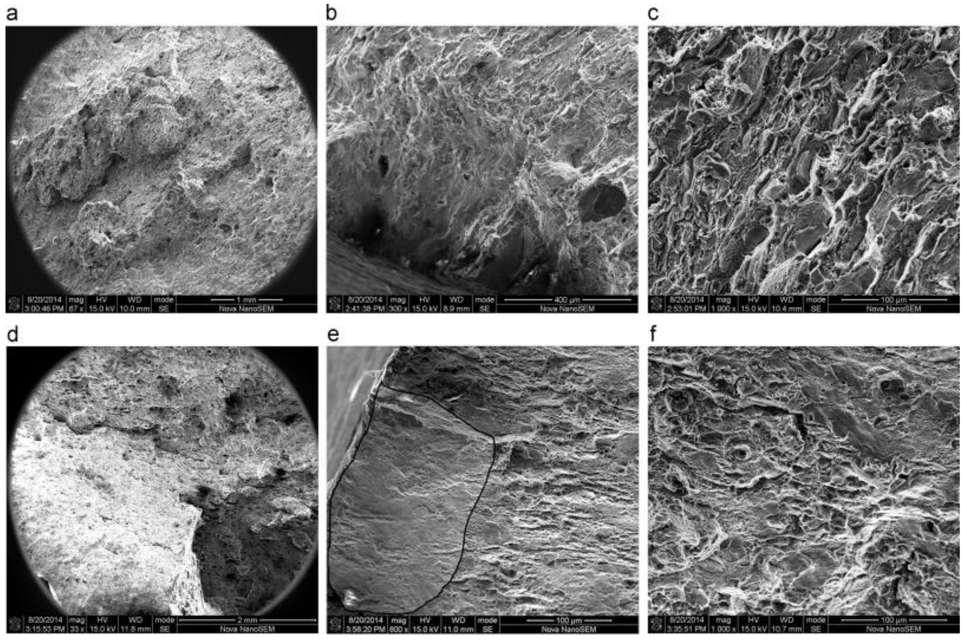
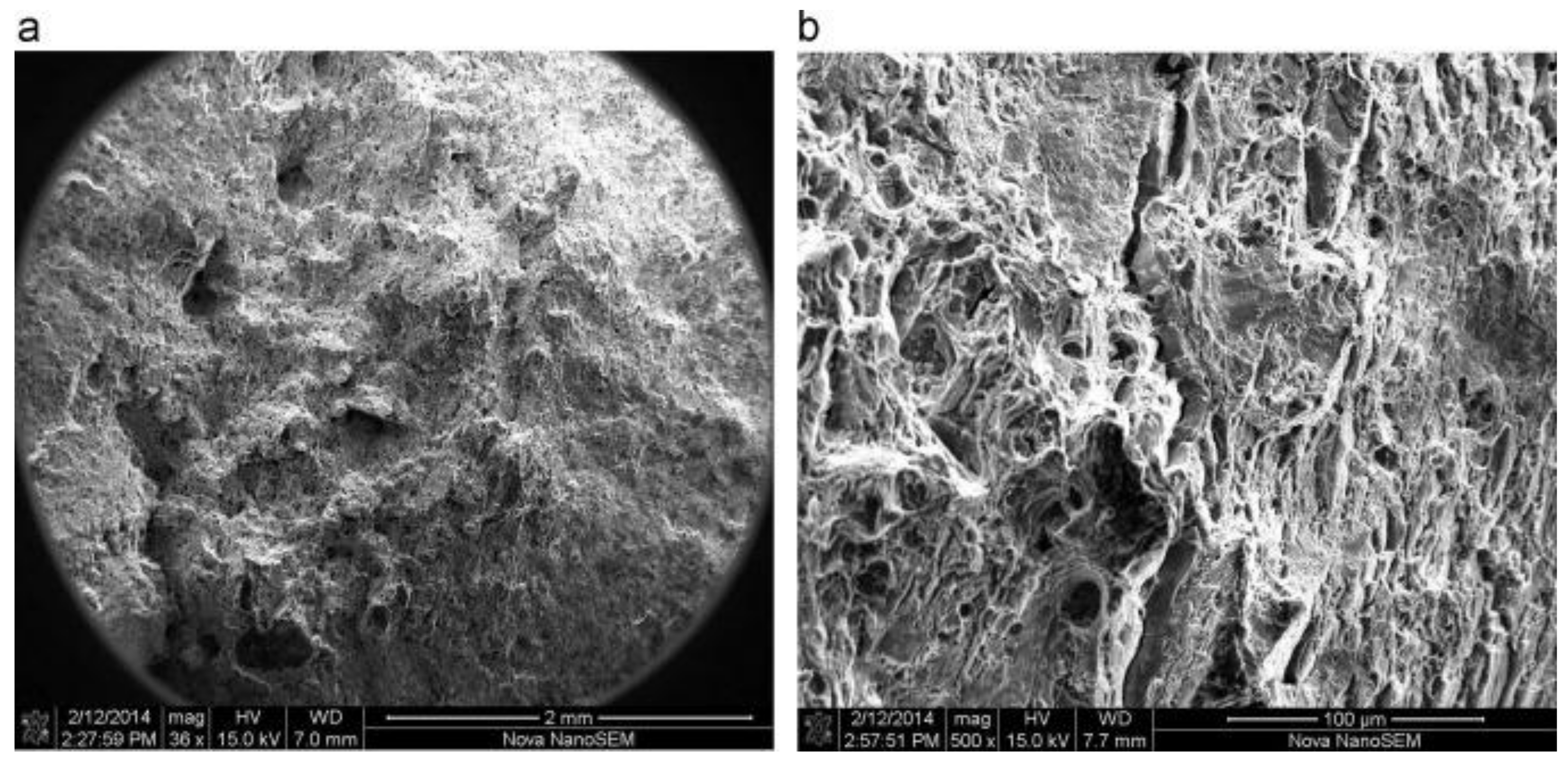
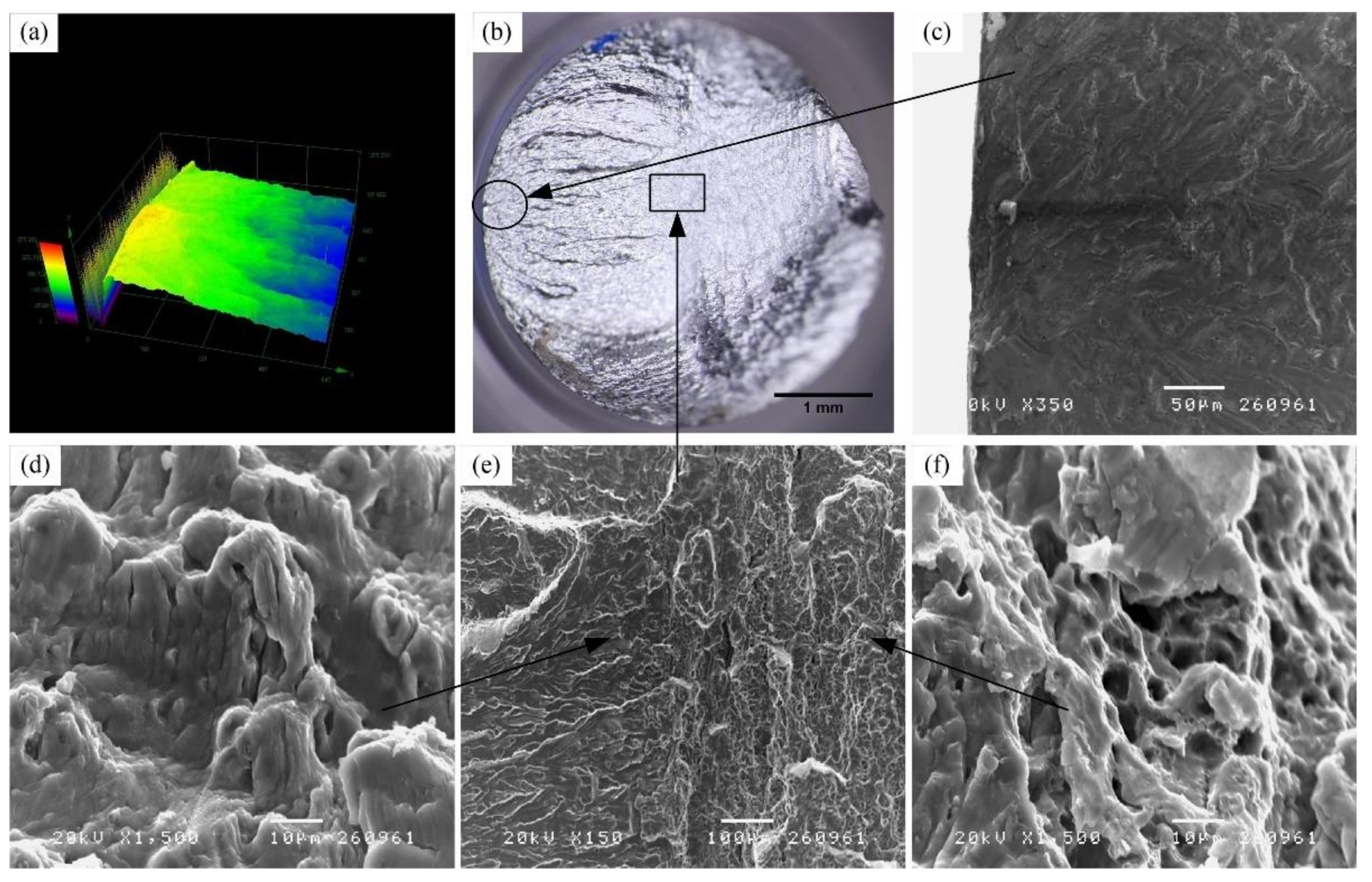
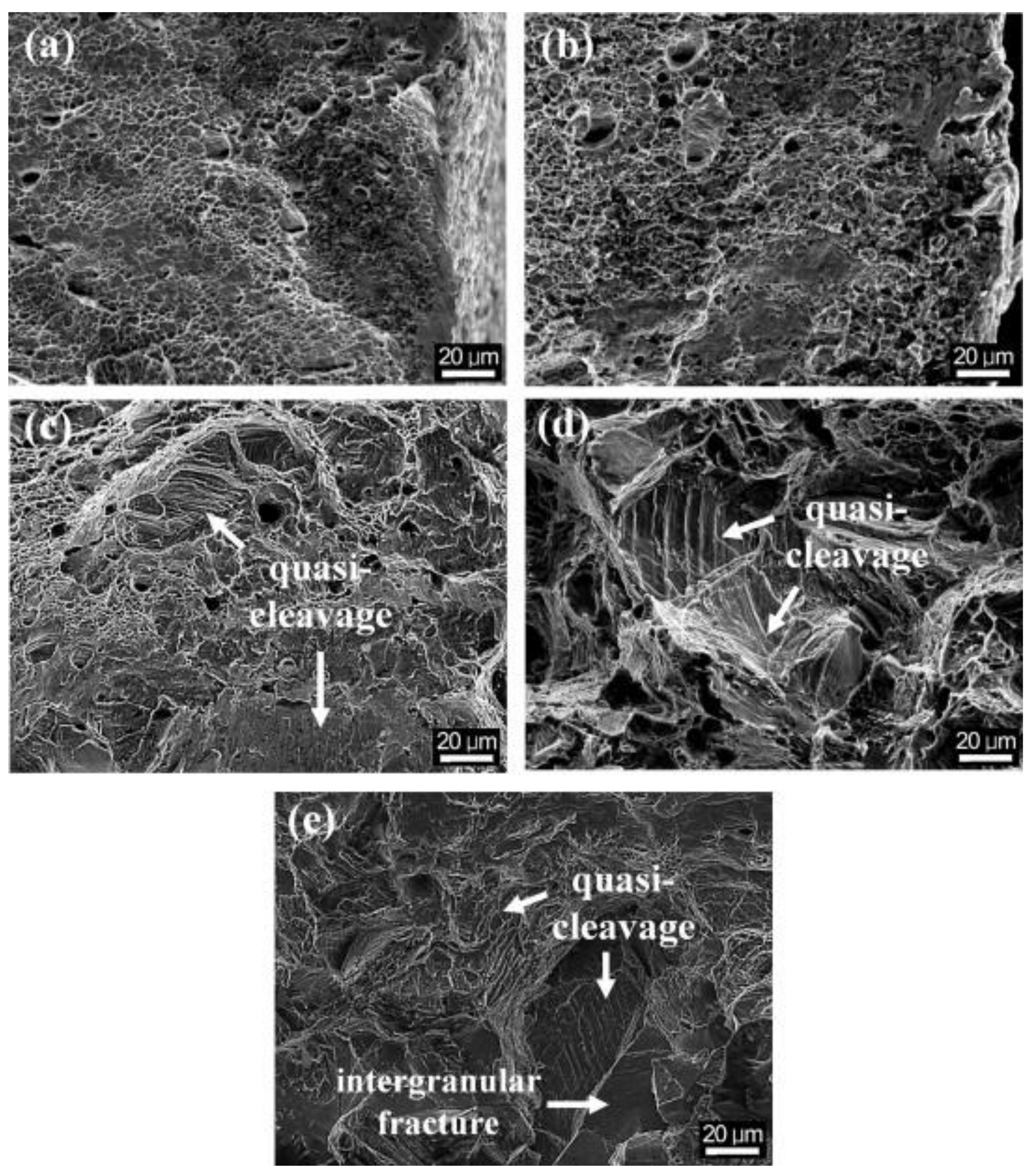
3.4. Microstructural Analysis

Microstructure analysis plays an important role in evaluating the HE susceptibility of materials. Scanning electron microscopy (SEM) and transmission electron microscopy (TEM) are widely used analytical tools to understand the internal microstructure of materials and the role of hydrogen in internal microstructure and material characterization [40]. Scanning electron microscopy is a universal and convenient method. Compared with other methods, the sample processing studied by this method is relatively simple [57].
In addition, SEM can provide three-dimensional images, which is particularly important when studying fracture structures such as micropores. Compared with other methods, the only disadvantage of this process is the low magnification and resolution.
Transmission electron microscopy (TEM) is the most effective and widely adopted technique. Compared with the poor magnification and low-resolution shortcomings of SEM, TEM can achieve the effect of magnifying millions of times and working with nanometer resolution. This method can also obtain crystal morphology information. However, the samples tested by this method have higher processing requirements. For TEM imaging, the sample must be electronically transparent. If TEM is used for microstructure analysis, the thickness of the sample must be less than 100 nm [58].
When studying the relationship between the mechanical properties and plastic deformation in the part formed by the hot forming-quenching integrated process (HFQ), which has been proved to be an effective forming method, achieving good formability and excellent mechanical properties simultaneously for aluminum alloys parts, SEM and TEM technology were used to observe the samples in order to observe the microstructure characteristics of the aluminum alloy parts to clarify the strengthening mechanism [59].
Gupta et al. [31] also used photomicrography techniques when studying aluminum alloys that have undergone heat treatment and deformation near the intergranular fracture surface. The observation results are shown in Figure 11.
SEM and 3D laser measurements are used to observe microscopic images of fracture of aluminum alloy [60]. The work is intended to study HE of aluminum alloy under high stress and low stress amplitude (the fewer the number of cycles), as shown in Figure 12. It is believed that the fracture of a material can be divided into three stages: initial crack formation, crack propagation, and finally material fracture. Figure 12c only shows one crack initiation site on each sample, and Figure 12d shows fatigue streaks that appear in the crack propagation stage of fatigue failure. Moreover, it can be seen that the fatigue fringes produced under high stress amplitude are wider than those produced under low stress amplitude. Finally, as shown in (f), the final fracture area of the sample shows a pitted surface.
Generally, hydrogen permeates the material first, then a suitable stretching method is used. Finally, it is microscopically analyzed to obtain the conclusions.

3.5. Hydrogen Microprint Technique (HMT)

In previous studies on hydrogen embrittlement of high-strength steels, in order to find out the path through which hydrogen can diffuse in the metal, the hydrogen microprint technique (HMT) is often used. If these paths are clear, then the specific microstructure of the path can be identified. At the same time, the influence of hydrogen must be known. This technique is very simple and unique, with higher accuracy and high resolution [36].
During this process, the surface of the hydrogen charging material is covered with a thin layer of AgBr gel. When hydrogen flows out of the metal, it reacts with the silver salt. After the reaction, metallic form of silver ion has created and leaves a track where hydrogen contact happened. Silver particles are present at this location and excess unreacted gel takes off from this location. The SEM inspected the sample during the inspection of the exit of hydrogen, where the silver was present [61,62,63].
However, this technique was mostly applied to the different steels such as in low carbon steel, high strength steel and austenitic stainless steel, its use on aluminum alloy still needs further improvement.

3.6. In-Situ SP Test Method

To evaluate HE behaviors in an external H2 condition, an in-situ SP test method using small-sized specimens under high-pressure H2 environments was established. In this method, one side of the specimen is exposed directly to high-pressure H2. This simple test method is known for its advantages: it requires a small amount of H2 (less than 50 cc), the test environment (temperature and pressure) is simple to set, and the impact of the punch speed is easy to obtain. By comparing RRT with the relative reduced area (RRA) obtained using SSRT, the in-situ SP test was first used to determine the HE behavior of austenitic stainless steel at various test temperatures [64]. Therefore, when applying the in-situ SP test method to various structural steels, it is necessary to accumulate sufficient data to ensure the applicability of these candidate materials for use with H2.

4. Prevention of Hydrogen Embrittlement

In order to guarantee safety, selection of the suitable prevention techniques becomes important. The prevention methods proposed by scholars in the past can be divided into two ideas. One is to block hydrogen from the material, that means using inhibition of film formation on aluminum alloy surface or coating methods. The other is to treat the material to make it more resistant to HE, including heat treatment methods and refining grain methods.

4.1. Inhibition of Film Formation on Aluminum Alloy Surface

4.1.1. Film Forming Method in an Alkaline Environment

Studies have pointed out that aluminum alloys in any water-containing environment (including humid air) have a tendency to form oxide or hydroxide surface films on the surface of the material [45,65]. According to this characteristic of aluminum alloy, Dey et al. [45] studied the possibility of surface film in 7075 aluminum alloy interfering with HE, hoping to enhance the resistance of aluminum alloy to H by this method. They conducted slow strain rate tests on this type of aluminum alloy in NaOH solution and NaCl solution. The NaOH-treated material shows a better effect of preventing HE during the subsequent hydrogen charging process. In contrast, due to the low OH content in NaCl, the effectiveness of NaCl-treated materials is not so significant. The research also found that the formed film is an oxide (or hydroxide) rich in Zn and Mg.
It can also be seen from the research results that when processing materials, making them form a surface film in an alkaline environment, or when aluminum alloy products work in an alkaline environment, can obtain better protection. In addition, the 7175 aluminum alloy and 7075 aluminum alloy mentioned above have similarities in composition. It can also be speculated that the 7175 aluminum alloy can also undergo a similar treatment to achieve a certain degree of anti-HE effect, but this conclusion has yet to be proved by experiments.

4.1.2. Acid Radical Suppression

Dichromate has strong adsorption and oxidizing properties for materials. At the same time, considering that the aluminum oxide film also has a certain effect of suppressing HE, based on this feature, Rocca et al. [66]. conducted SEM observations on aluminum alloy materials treated with several acid radical solutions. Studies have shown that in treated materials, acid radicals can stimulate the repair of defect areas of the surface film and oxidize active parts, resulting in the formation of a stable corrosion-resistant barrier film. In addition, the inhibitory ability of Cr2O72− and MoO42− is also compared, as shown in the SEM scan. It is obviously to see that the surface of the alloy treated in the Cr2O72− containing solution is smooth, without defect areas or pits. While the material treated at the same time in the MoO42− containing solution at the same pH still has some defect areas. The surface of the sample is shown in Figure 13.
The research results also pointed out that the passivation film formed by the dichromate-treated material significantly improved the efficiency of suppressing HE due to the content of Cr(0) and Cr(Ⅲ).

4.1.3. Sodium Silicate Solution Inhibition Method

When studying hydrogen storage bottles, some scholars found that gas tungsten arc welding (GTAW) welding joints between the bottle cap made of 7075 aluminum alloy (Al-Zn-Mg) and the bottle body will also cause serious problems such as the phenomenon of HE. Considering that it is caused by the penetration of hydrogen that gets into the microcracks, they proposed coating the surface of the welding zone with sodium silicate solution to deal with HE and focus on the depth of hydrogen penetration, as shown in Figure 14.

4.2. Coatings

4.2.1. Cadmium and Nickel Coatings

In the production process of hydrogen storage tanks, there is a film coated on the liner to improve its performance, which shows that it is a good idea to suppress HE from the inner layer. Hillier worked on the alloying of zinc and nickel and found that the hydrogen penetration in steel can be reduced by applying the following methods. It is found that the nickel deposited on the material first forms a layer of nickel on the material and acts as a hydrogen barrier [67]. The diffusion coefficient of hydrogen in nickel is very low, only 1.2 × 10⁻¹⁰ m2 s−1. In the material, whether hydrogen can pass through the coating depends on the diffusion rate of hydrogen in the coating. In addition, in some cases, the absorbed hydrogen atoms will combine to form a molecule before entering a location, and inside the coating, they escape and form bubbles. Cadmium is responsible for recombination of hydrogen in a coating and reducing the entry of hydrogen coating [66,67]. The diffusion coefficient of hydrogen in various elements is shown in Table 1 [66,68].

4.2.2. Other Metal Coatings

The use of coated metal to prevent HE is more common. When some materials (such as Pt, Cu, and Ni) are used as a protective layer, they introduce a thin layer above the surface of the aluminum alloy material, which can reduce the penetration of hydrogen in the aluminum alloy. Gold, tin and certain tin-lead alloy coatings are also very effective and can act as a barrier to hydrogen penetration [69].

4.2.3. Metal Oxide for Coating

In the past, people mostly used pure metal as a plating method to block the diffusion of hydrogen atoms. However, due to the difficulty of solving many problems related to hydrogen, the research on the problem of hydrogen permeation barrier has been stagnant. In order to effectively reduce the risk of HE, previous studies on the problem of hydrogen permeation barrier were summarized [70]. It also found that aluminum oxide film has a good effect as a hydrogen permeation barrier due to its compact nature. People have also made certain optimizations for the deposition technology of aluminum oxide film. Considering the working environment of many aluminum alloy, the author believes that relying solely on chromium oxide as a barrier is not feasible.

4.2.4. Nitride as Coating

Because of the wide application of nitrides as hard coatings and decorative films, the density and uniformity shown during filling are thought to be a new effective hydrogen permeation barrier. When Checchetto [71] studied BN, its performance as a hydrogen permeation barrier on the surface of stainless steel was excellent. Melendez et al. [68] studied TiN and found that coating a 1 µm thick TiN film on a stainless steel sample with a thickness of 0.35 mm has much better performance. In addition, Bazzanella et al. [72] studied the role of aluminum in TiN coatings and found that aluminum easily forms compounds with O, thereby preventing Ti oxidation. Furthermore, TiAlN is considered to be a new and effective hydrogen permeation barrier, and its performance is even higher than that of TiN films.
It is not difficult to see how to ensure that another element does not fail due to oxidation or other factors when using nitride as a coating protection is an issue worthy of attention. Moreover, although many scholars are studying HE with high-strength steel, and the object of the proposed solution is also high-strength steel, the method of coating protection is theoretically applicable to aluminum alloys, but it still needs experimental verification.

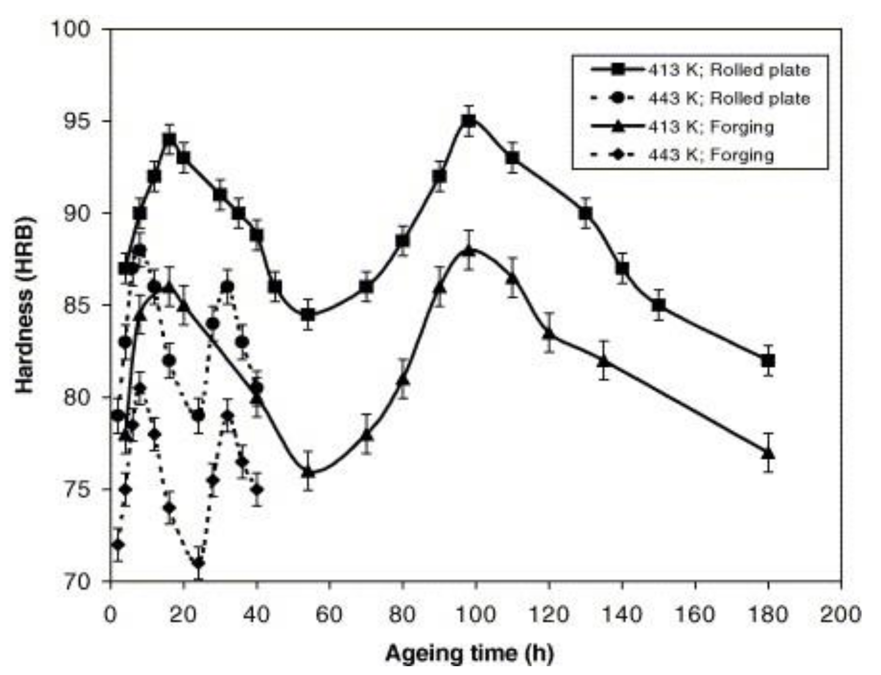
4.3. Heat Treatment of Materials
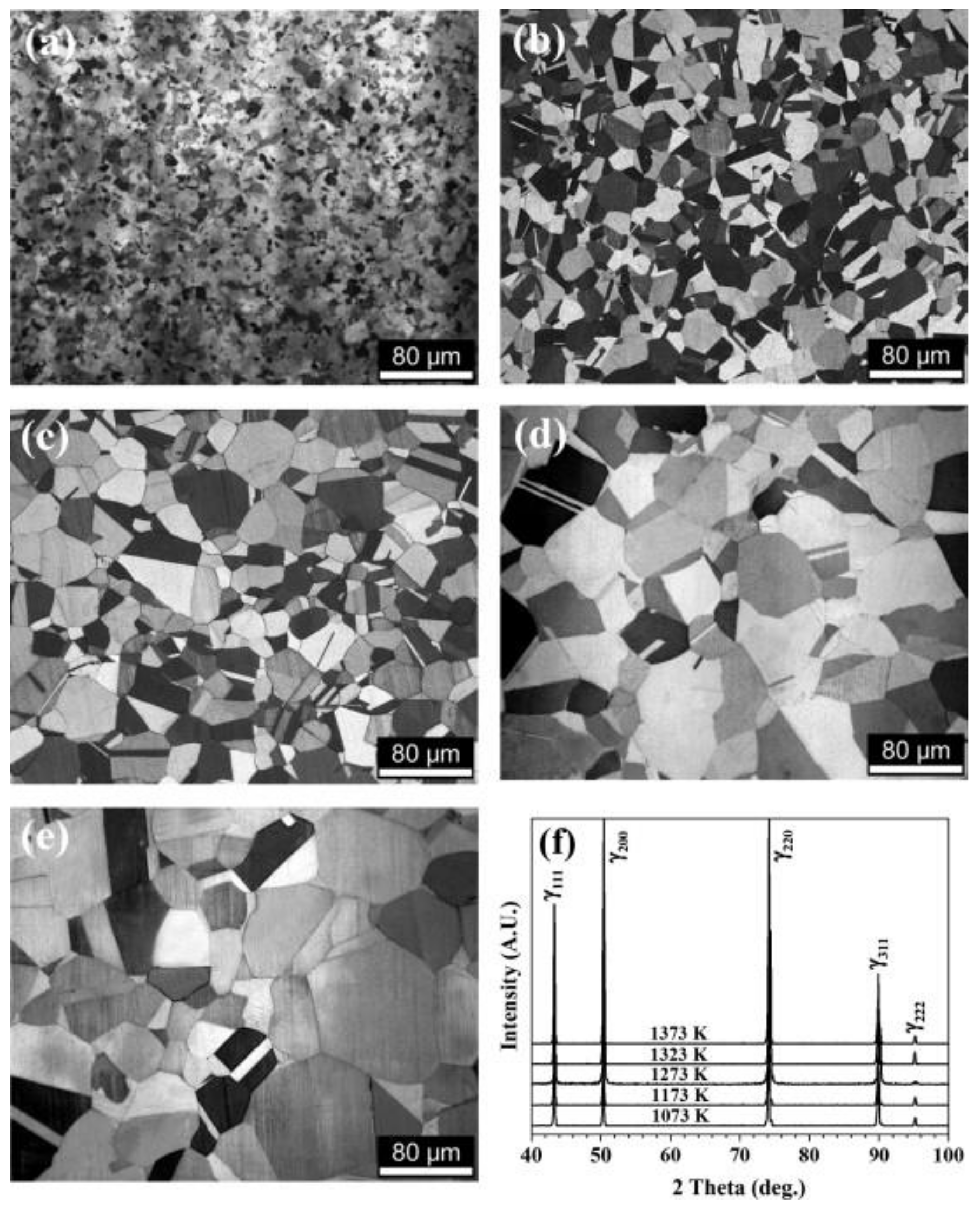
Wu et al. [68] studied the HE sensitivity of GCr15 bearing steel under two heat treatment methods: quenching and tempering (QT) and pre-quenching and austenite tempering (PQA). The results show that the PQA-treated samples have higher mechanical stability. The indentation test and hydrogen bubble experiment show that the PQA-treated samples are less sensitive to hydrogen. Moreover, the hydrogen penetration test also showed significant differences in the diffusion coefficient and the number of hydrogen capture sites between QT and PQA specimens [73].
From the perspective of heat treatment, Song et al. [41] studied the aluminum alloy and found that 7175 aluminum alloy has two peak aging states when aging at 413–443 K, as shown in Figure 15.
The strength of the second peak aging state is slightly higher than the first peak aging state aged at 413 K, and it has better resistance to HE of the material. This phenomenon also shows that its potential practical application is that 7175 aluminum alloy can be heat treated to high strength, while making it have high HE resistance. At the same time, after in-depth research, it is found that heat treatment can change the size and distribution of the precipitated phases in the grain and the grain boundary, and can inhibit HE, thereby improving the mechanical properties and HE resistance of the alloy [74].

4.4. Grain Refining

Relevant experiments have shown that vibrating the sample will reduce the size of the crystallized crystals. In addition, the size of the crystal grains will significantly affect the HE of the material. As the crystal grain size decreases, the HE sensitivity of the material decreases [18,75,76,77]. As the annealing temperature increased from 1073 to 1373 K, the average grain size increased from 6.4 to 79.8 μm [78]. The schematic diagram is shown in Figure 16.
On this basis, Park et al. [78] carried out tensile experiments on hydrogen-charged samples. SEM is also used to observe the fracture surfaces of hydrogen-free and hydrogen-charged samples, as shown in Figure 17. Regardless of the grain size, all specimens without hydrogen exhibited ductile fracture surfaces with well-developed pits. The hydrogen samples showed different fracture surfaces according to the grain size. When the grain size is less than about 20 μm, ductile fracture surfaces are observed even at the edge of the tensile specimen (Figure 17a,b). However, when the grain size is greater than about 20 μm, only the central part of the sample shows a ductile fractured surface, while the edge part shows a quasi-cracked and intergranular fractured surface (Figure 17c–e).
The study also found that hydrogen atoms are more active in coarse grains and proposed that grain refinement can inhibit the transition from ductility to brittleness of steel, thereby suppressing HE. In order to further explore the influence of crystal grains on hydrogen diffusion coefficient, some scholars have established a finite element model for simulation. The final simulation results show that grain refinement can indeed significantly reduce the hydrogen diffusion coefficient of the sample [78].

5. Discussion

By sorting out the mechanisms, the authors believe that the mechanism of HE can be mainly proposed based on three aspects: hydrogen reduces the bonding force between atoms, hydrogen-induced local deformation of materials and hydrogen pressure. However, the above three theories also have unique features. For example, the hydrogen- enhanced decohesion mechanism (HEDE) states that hydrogen reduces the force between atoms, which in turn causes cracks to develop and eventually cause HE [79]. The hydrogen-enhanced local plasticity model (HELP) states alloys are prone to dislocations and that these dislocations easily trap hydrogen. Some scholars have proposed the use of heat treatment to treat materials and improve performance, which are also introduced below. It is worth mentioning that the synergistic action between the hydrogen-enhanced plasticity (HELP) and hydrogen-enhanced decohesion (HEDE) in steel has been the subject of extensive research, which means that the HE of aluminum alloys may also be the result of a combination of multiple mechanisms. In general, in terms of HE mechanisms, it has been accepted by most scholars that HELP is the main factor [80] that the coexistence of multiple other factors, may lead to HE.
In fact, the sources of hydrogen atoms may be various, such as welding, pickling, the working environment, etc. Identifying the source of hydrogen atoms plays a key role in determining the hydrogen embrittlement mechanisms and prevention measures for hydrogen storage tanks. For the vehicle-mounted hydrogen storage tanks made by aluminum alloy which are filled with liquid hydrogen, its internal pressure is mostly 35 MPa or 70 MPa, the hydrogen pressure theory may be the main reason for its failure.
The entire experimental detection procedure for HE is expounded systematically. Although the hydrogen permeation method and corrosion simulation program used in previous experiments to process materials are more practical, they are still different from the working environment of most aluminum alloys. Therefore, the experimental results may be slightly different from the actual phenomenon, which remains to be a more reasonable experimental method is proposed. For example, there is still a lack of simulation experiments for the environment of hydrogen storage bottles with high pressure, airtight, and liquid hydrogen.
Especially, in terms of experimental methods, there are clear standards for sample pretreatment and size cutting, so there will be no major changes. However, in the observation of the sample after the test, transmission electron microscopy (TEM) is the most effective and widely adopted technique. Compared with the shortcomings of SEM magnification and low resolution, TEM can achieve the effect of magnifying millions of times and working with nanometer resolution. The authors believe that this will be more widely used in future work.
For example, in the electrochemical cathode hydrogen permeation method, the electrolyte solution contains many components, which may also have a certain impact on the HE of aluminum alloys. Therefore, when the experimental method involves a solution, especially when it contains many ionic components, the possible effect of the ion composition on aluminum alloy materials should be considered. If the experimental method involves contact with air, the effect of oxygen in the air on the aluminum alloy should also be considered.
From the summary of the predecessor works, the focus of this work is to find effective ways to alleviate hydrogen embrittlement. Although some preventive measures are proposed for high-strength steel, they also have certain a reference significance for the prevention of HE in aluminum alloy materials. Moreover, the starting point for most of the prevention measures is still based on coating the metal. Obviously, this method also depends on the selection of more suitable coating materials and the application of better coating technology. Someone in the authors’ unit once wanted to spray aluminum particles onto the surface of high-strength steel by cold spraying technology, and achieved good results [81]. Although on the one hand it illustrates the feasibility and reliability of the coating idea, it does not mean that the aluminum alloy is on the surface. When dealing with HE, similar measures cannot be taken.
The previous article mentioned the use of grain refinement to suppress HE, but how to effectively refine the grains is still a problem worthy of discussion. Lu [82] pointed out in his research that although the material processed by grain refinement has high strength and hardness, the plasticity and toughness are also significantly reduced. Therefore, he proposed to overcome the problem by multi-level construction of nanomaterials, the above performance shortcomings and give play to the advantages of materials. Also for aluminum alloy materials, this approach can be used to construct multi-level nanomaterials, which not only have excellent performance, but also have a good effect in preventing HE.
Considering that the specific working environment of the hydrogen storage tank is filled with liquid hydrogen, the acid radical suppression method and the alkaline environment film forming method may not be available. As for the heat treatment method, plating and coating prevention method are good ideas. In actual applications, the use of heat treatments to treat the material of the hydrogen storage bottle to a certain extent, and then integrate the plating and coating methods to further optimize the inner tank can be considered too.
In the future, people should pay more attention to the development of the higher strength and more corrosion-resistant aluminum alloys. In order to reduce the need forwelding and avoid hydrogen embrittlement at the joints, some advanced integral forming technologies, such as soft mold forming, hydroforming or electromagnetic forming can be applied. Some new coating and surface treatment technologies should be developed to realize the isolation of hydrogen and aluminum alloy. Finally, it is essential to develop more accurate non-destructive testing technology for the detection of hydrogen embrittlement.

6. Conclusions

Hydrogen embrittlement (HE) is a severe type of failure that affects aluminum alloys. Serious HE of hydrogen tanks represents a huge danger to the safety of vehicles and passengers. The analysis, including the derivative mechanisms, detection technologies and prevention measures of HE for aluminum alloy are summarized. Moreover, the research ideas for further exploration are provided. Better understanding of the various mechanisms, detection and prevention in aluminum alloy are beneficial for the development of safer hydrogen vehicles and other transportation equipment. The following conclusions can be drawn:
(1)
The HE mechanisms of aluminum alloy mainly include the hydrogen enhanced local plasticity model (HELP), the hydrogen enhanced decohesion mechanism (HEDE) and the hydrogen pressure theory. The HELP is widely accepted. This theory holds that through stress-induced diffusion, hydrogen atoms are concentrated to the crack tip, leading to fracture of materials.
(2)
The HE detection methods mainly includes slow strain rate test (SSRT), linearly increasing stress test (LIST) and tools to measure hydrogen content (TDS). Scanning electron microscopy (SEM) and transmission electron microscopy (TEM) are also used for microstructure analysis. Among the methods to conduct the tensile experiments, LIST has the advantages of simple operation and easy process.
(3)
The HE prevention methods mainly involve surface film formation suppression methods, coating prevention methods, heat treatment methods and grain refining methods. Among these, the sodium silicate solution inhibition method effectively prevents hydrogen from penetrating into microscopic cracks during the production of the hydrogen storage tanks. It is also believed that further prevention measures will be developed based on the integration of multiple prevention methods.

Author Contributions

Y.C.: Investigation, Writing—Original Draft, Funding acquisition. S.Z.: Writing—Original Draft. H.M.: Conceptualization, Methodology, Project administration, Funding acquisition. H.W.: Conceptualization, Project administration. L.H.: Writing—Review & Editing, Funding acquisition. S.F.: Writing—Review & Editing. All authors have read and agreed to the published version of the manuscript.

Funding

The authors would like to acknowledge the financial support from the National Natural Science Foundation Council of China (Grant No. 51905395, 51775398, 51805392), the Program for Innovative Research Team in University of Education Ministry (Grant No.IRT_17R83), Nature Science Foundation of Hubei Province (Grant No. 2020CFB550, No. 2018CFB595), the 111 Project (B17034), and the Fundamental Research Funds for the Central Universities (Grant No. WUT: 2020III004XZ, 2020IVB021,2019IVB022, 2019IVA026, 2018III074GX, 2018III067GX, 2020-QC-B1-07), and the State Key Laboratory of Materials Processing and Die & Mould Technology (Grant No. P2019-010).

Institutional Review Board Statement

Not applicable.

Informed Consent Statement

Not applicable.

Data Availability Statement

Not applicable.

Conflicts of Interest

The authors declare no conflict of interest.

References

  1. Ambituuni, A.; Amezaga, J.M.; Werner, D. Risk assessment of petroleum product transportation by road: A framework for regulatory improvement. Saf. Sci. 2015, 79, 324–335. [Google Scholar] [CrossRef] [Green Version]
  2. Fleming, C.H.; Spencer, M.; Thomas, J.; Leveson, N.; Wilkinson, C. Safety assurance in NextGen and complex transportation systems. Saf. Sci. 2013, 55, 173–187. [Google Scholar] [CrossRef]
  3. Ji, M.; You, X.; Lan, J.; Yang, S. The impact of risk tolerance, risk perception and hazardous attitude on safety operation among airline pilots in China. Saf. Sci. 2011, 49, 1412–1420. [Google Scholar] [CrossRef]
  4. Greene, D.L.; Ogden, J.M.; Lin, Z. Challenges in the designing, planning and deployment of hydrogen refueling infrastructure for fuel cell electric vehicles. eTransportation 2020, 6, 100086. [Google Scholar] [CrossRef]
  5. Michler, T.; Wackermann, K.; Schweizer, F. Review and Assessment of the Effect of Hydrogen Gas Pressure on the Embrittlement of Steels in Gaseous Hydrogen Environment. Metals 2021, 11, 637. [Google Scholar] [CrossRef]
  6. Kansara, S.; Gupta, S.K.; Sonvane, Y.; Gajjar, P.N. Ultrathin Pd and Pt nanowires for potential applications as hydrogen economy. Mater. Today Commun. 2021, 26, 101761. [Google Scholar] [CrossRef]
  7. Schaupp, T.; Schroeder, N.; Schroepfer, D.; Kannengiesser, T. Hydrogen-Assisted Cracking in GMA Welding of High-Strength Structural Steel—A New Look into This Issue at Narrow Groove. Metals 2021, 11, 904. [Google Scholar] [CrossRef]
  8. Ajanovic, A.; Haas, R. Prospects and impediments for hydrogen and fuel cell vehicles in the transport sector. Int. J. Hydrogen Energy 2020, 46, 10049–10058. [Google Scholar] [CrossRef]
  9. Gong, L.; Li, Z.; Jin, K.; Gao, Y.; Duan, Q.; Zhang, Y.; Sun, J. Numerical study on the mechanism of spontaneous ignition of high-pressure hydrogen during its sudden release into a tube. Saf. Sci. 2020, 129, 104807. [Google Scholar] [CrossRef]
  10. Wang, Y. Research on the Hydrogen Supply System of 70 MPa Hydrogen Storage Cylinder for Vehicles and the Fast Filling Process; Dalian University of Technology: Dalian, China, 2019. [Google Scholar]
  11. Zhang, M.; Lv, H.; Kang, H.; Zhou, W.; Zhang, C. A literature review of failure prediction and analysis methods for composite high-pressure hydrogen storage tanks. Int. J. Hydrogen Energy 2019, 44, 25777–25799. [Google Scholar] [CrossRef]
  12. Allam, T.; Guo, X.; Lipińska-Chwałek, M.; Hamada, A.; Ahmed, E.; Bleck, W. Impact of precipitates on the hydrogen embrittlement behavior of a V-alloyed medium-manganese austenitic stainless steel. J. Mater. Res. Technol. 2020, 9, 13524–13538. [Google Scholar] [CrossRef]
  13. Venezuela, J.; Zhou, Q.; Liu, Q.; Li, H.; Zhang, M.; Dargusch, M.S.; Atrens, A. The influence of microstructure on the hydrogen embrittlement susceptibility of martensitic advanced high strength steels. Mater. Today Commun. 2018, 17, 1–14. [Google Scholar] [CrossRef]
  14. Talbot, D.E.J. Effects of Hydrogen in Aluminium, Magnesium, Copper, and Their Alloys. Int. Metall. Rev. 1975, 20, 166–184. [Google Scholar] [CrossRef]
  15. Wang, H.; Deng, W.; Zhang, T.; Yao, J.; Wang, S. Development of Elastoplastic-Damage Model of AlFeSi Phase for Aluminum Alloy 6061. Metals 2021, 11, 954. [Google Scholar] [CrossRef]
  16. Xiao, Q.; Xu, Y.; Huang, J.; Li, B.; Wang, B.; Liu, S.; Fu, L. Effects of quenching agents, two-step aging and microalloying on tensile properties and stress corrosion cracking of Al-Zn-Mg-Cu alloys. J. Mater. Res. Technol. 2020, 9, 10198–10208. [Google Scholar] [CrossRef]
  17. Kim, H.; Lee, M.; Yoon, S.; Vucko, F.; Lee, C.; Theirry, D.; Kim, S. Diffusible hydrogen behavior and delayed fracture of cold rolled martensitic steel in consideration of automotive manufacturing process and vehicle service environment. J. Mater. Res. Technol. 2020, 9, 13483–13501. [Google Scholar] [CrossRef]
  18. Li, L.X.; Sun, M.H.; Fan, M.C.; Yang, T.S.; Du, F.S. New Rapid prototyping technology for the prevention of hydrogen embrittlement of metal strips. Corros. Sci. 2020, 164, 108341. [Google Scholar] [CrossRef]
  19. Moshtaghi, M.; Safyari, M.; Kuramoto, S.; Hojo, T. Unraveling the effect of dislocations and deformation-induced boundaries on environmental hydrogen embrittlement behavior of a cold-rolled Al–Zn–Mg–Cu alloy. Int. J. Hydrogen Energy 2021, 46, 8285–8299. [Google Scholar] [CrossRef]
  20. Sajjad, U.; Abbas, A.; Sadeghianjahromi, A.; Abbas, N.; Liaw, J.; Wang, C. Enhancing corrosion resistance of Al 5050 alloy based on surface roughness and its fabrication methods; an experimental investigation. J. Mater. Res. Technol. 2021, 11, 1859–1867. [Google Scholar] [CrossRef]
  21. Wang, H.; Liu, H.; Yao, J.; Ye, D.; Lang, Z.; Glowacz, A. Mapping the knowledge domains of new energy vehicle safety: Informetrics analysis-based studies. J. Energy Storage 2021, 35, 102275. [Google Scholar] [CrossRef]
  22. Wu, S.; Cheng, W.; Yang, J.H.C.; Yang, C.; Liao, S. The corrosion protection study on inner surface from welding of aluminum alloy 7075-T6 hydrogen storage bottle. Int. J. Hydrogen Energy 2016, 41, 570–596. [Google Scholar] [CrossRef]
  23. Luo, T.; Peng, Y.; Guo, Y.; Cao, J. Influence of interactions between hydrogen and (101¯2) twin boundary on hydrogen embrittlement in α-Ti. Mater. Today Commun. 2021, 26, 101802. [Google Scholar] [CrossRef]
  24. Song, R.G.; Blawert, C.; Dietzel, W.; Atrens, A. A study on stress corrosion cracking and hydrogen embrittlement of AZ31 magnesium alloy. Mater. Sci. Eng. A 2005, 399, 308–317. [Google Scholar] [CrossRef]
  25. Borrego, L.P.; Costa, J.M.; Antunes, F.V.; Ferreira, J.M. Fatigue crack growth in heat-treated aluminium alloys. Eng. Fail. Anal. 2010, 17, 11–18. [Google Scholar] [CrossRef] [Green Version]
  26. Metalnikov, P.; Eliezer, D.; Ben-Hamu, G.; Tal-Gutelmacher, E.; Gelbstein, Y.; Munteanu, C. Hydrogen embrittlement of electron beam melted Ti–6Al–4V. J. Mater. Res. Technol. 2020, 9, 16126–16134. [Google Scholar] [CrossRef]
  27. Wang, J.; Ma, L.; Han, M.; Jia, J. Molecular and dissociated adsorption of hydrogen on TiC6H6. Int. J. Hydrogen Energy 2019, 44, 25800–25808. [Google Scholar] [CrossRef]
  28. Mayer, T.; Semmel, M.; Guerrero Morales, M.A.; Schmidt, K.M. Techno-economic evaluation of hydrogen refueling stations with liquid or gaseous stored hydrogen. Int. J. Hydrogen Energy 2019, 44, 25809–25833. [Google Scholar] [CrossRef]
  29. Zhao, L.; Li, F.; Li, Z.; Zhang, L.; He, G. Thermodynamic analysis of the emptying process of compressed hydrogen tanks. Int. J. Hydrogen Energy 2019, 44, 3993–4005. [Google Scholar] [CrossRef]
  30. Bakare, A.K.; Shaikh, A.A.; Kale, S.S. Corrosion behaviour of stop-hole and notch instead of crack in thin aluminium alloy sheet repaired with bonded patch exposed to saline environment under constant load. Eng. Fail. Anal. 2021, 120, 105067. [Google Scholar] [CrossRef]
  31. Gupta, C.; Toda, H.; Fujioka, T.; Kobayashi, M.; Hoshino, H.; Uesugi, K.; Takeuchi, A.; Suzuki, Y. State of 3-D micro-damage in hydrogen redistributed regions of precharged high strength aluminium alloy. Corros. Sci. 2016, 111, 26–38. [Google Scholar] [CrossRef]
  32. Qi, W.J. A Study on Hydrogen-Induced Cracking Mechanism of 7050 High Strength Aluminum Alloy; Changzhou University: Changzhou, China, 2015. [Google Scholar]
  33. Xie, Z.; Wang, Y.; Lu, C.; Dai, L. Sluggish hydrogen diffusion and hydrogen decreasing stacking fault energy in a high-entropy alloy. Mater. Today Commun. 2021, 26, 101902. [Google Scholar] [CrossRef]
  34. Verners, O.; Psofogiannakis, G. Comparative molecular dynamics study of fcc-Al hydrogen embrittlement. Corros. Sci. 2015, 98, 40–49. [Google Scholar] [CrossRef] [Green Version]
  35. Lynch, S. Hydrogen embrittlement phenomena and mechanisms. Corros. Rev. 2012, 30, 105–123. [Google Scholar] [CrossRef]
  36. Dwivedi, S.K.; Vishwakarma, M. Hydrogen embrittlement in different materials: A review. Int. J. Hydrogen Energy 2018, 43, 21603–21616. [Google Scholar] [CrossRef]
  37. Rao, A.C.U.; Vasu, V.; Govindaraju, M. Stress corrosion cracking behavior of 7xxx aluminum alloys: A literature review. Trans. Nonferrous Met. Soc. China 2016, 26, 1447–1471. [Google Scholar] [CrossRef]
  38. Liang, S.; Huang, M.S.; Zhao, L.; Zhu, Y.X.; Li, Z.H. Effect of multiple hydrogen embrittlement mechanisms on crack propagation behavior of FCC metals: Competition vs. synergy. Int. J. Plast. 2021, 143, 103023. [Google Scholar] [CrossRef]
  39. Fukai, Y. Formation of superabundant vacancies in M-H alloys and some of its consequences: A review. J. Alloys Compd. 2003, 356–357, 263–269. [Google Scholar] [CrossRef]
  40. Panagopoulos, C.; Papapanayiotou, P. The influence of cathodic hydrogen charging on the mechanical behavior of Al-Zn-Mg alloy. J. Mater. Sci. 1995, 30, 3449–3456. [Google Scholar] [CrossRef]
  41. Rin, T. Hydrogen generation from the hydrolysis of aluminum promoted by NieLieB catalyst. Int. J. Hydrogen Energy 2021, 46, 28450–28461. [Google Scholar] [CrossRef]
  42. Lv, H.; Zhao, H.; Zuo, Z.; Li, R.; Liu, F. A thermodynamic and kinetic study of catalyzed hydrolysis of aluminum nitride in secondary aluminum dross. J. Mater. Res. Technol. 2020, 9, 9735–9745. [Google Scholar] [CrossRef]
  43. Song, R.G.; Dietzel, W.; Zhang, B.J.; Liu, W.J.; Tseng, M.K.; Atrens, A. Stress corrosion cracking and hydrogen embrittlement of an Al–Zn–Mg–Cu alloy. Acta Mater 2004, 52, 4727–4743. [Google Scholar] [CrossRef]
  44. Wang, H.; Cheng, X.; Zhang, Y.G.; Wang, M.M.; Zhao, B.L.; Xie, Z.M. Hydrogen embrittlement of bulk W-0.5 wt% ZrC alloy induced by annealing in hydrogen atmosphere. J. Nucl. Mater. 2021, 556, 153177. [Google Scholar] [CrossRef]
  45. Dey, S.; Chattoraj, I. Interaction of strain rate and hydrogen input on the embrittlement of 7075 T6 Aluminum alloy. Mater. Sci. Eng. A 2016, 661, 168–178. [Google Scholar] [CrossRef]
  46. Álvarez, G.; Zafra, A.; Belzunce, F.J.; Rodríguez, C. Hydrogen embrittlement testing procedure for the analysis of structural steels with Small Punch Tests using notched specimens. Eng. Fract. Mech. 2021, 253, 107906. [Google Scholar] [CrossRef]
  47. Petroyiannis, P.V.; Kermanidis, A.T.; Papanikos, P.; Pantelakis, S.G. Corrosion-induced hydrogen embrittlement of 2024 and 6013 aluminum alloys. Trans. Nonferrous Met. Soc. China 2004, 41, 173–183. [Google Scholar] [CrossRef]
  48. ASTM E8m-94a. Standard Test Methods for Tension Testing of Metallic Materials; American Society for Testing Material: West Conshohocken, PA, USA, 2009. [Google Scholar]
  49. ASTM E561-94. Standard Test Method for Kr Curve Determination; American Society for Testing Material: West Conshohocken, PA, USA, 2015. [Google Scholar]
  50. ASTM G34-90. Adjunct to G34 Test Method for Exfoliation Corrosion Susceptibility in 2Xxx and 7Xxx Series Aluminum Alloys (Exco Test); American Society for Testing Material: West Conshohocken, PA, USA, 2010. [Google Scholar]
  51. ASTM G129-2000(R2013). Standard Practice for Slow Strain Rate Testing to Evaluate the Susceptibility of Metallic Materials to Environmentally Assisted Cracking; American Society for Testing Material: West Conshohocken, PA, USA, 2013. [Google Scholar]
  52. ASTM A370. Standard Test Methods and Definitions for Mechanical Testing of Steel Products; American Society for Testing Material: West Conshohocken, PA, USA, 2010. [Google Scholar]
  53. Zhang, J.; Jiang, P.; Chen, Q.; Zhou, J.; Meng, Y. Tensile properties and strain hardening mechanism of Cr-Mn-Si-Ni alloyed ultra-strength steel at different temperatures and strain rates. J. Alloys Compd. 2020, 842, 155856. [Google Scholar] [CrossRef]
  54. Venezuela, J.; Liu, Q.; Zhang, M.; Zhou, Q.; Atrens, A. The influence of hydrogen on the mechanical and fracture properties of some martensitic advanced high strength steels studied using the linearly increasing stress test. Corros. Sci. 2015, 99, 98–117. [Google Scholar] [CrossRef] [Green Version]
  55. Villalba, E.; Atrens, A. Metallurgical aspects of rock bolt stress corrosion cracking. Mater. Sci. Eng. A 2008, 491, 8–18. [Google Scholar] [CrossRef]
  56. Irwanto, B. Influence of hydrogen on the mechanical properties of some medium-strength Ni–Cr–Mo steels. Mater. Sci. Eng. A 2014, 617, 200–210. [Google Scholar]
  57. Liu, Q. The influence of hydrogen on 3.5NiCrMoV steel studied using the linearly increasing stress test. Corros. Sci. J. Environ. Degrad. Mater. Control. 2013, 67, 193–203. [Google Scholar] [CrossRef]
  58. Pedergnana, A.; Ollé, A.; Evans, A.A. A new combined approach using confocal and scanning electron microscopy to image surface modifications on quartzite. J. Archaeol. Sci. Rep. 2020, 30, 102237. [Google Scholar] [CrossRef]
  59. Li, H.; Hu, Z.; Chen, Y.; Sun, Q. Modeling mechanical properties and plastic strain for hot forming-quenching AA6061 aluminum alloy parts. Int. J. Lightweight Mater. Manuf. 2020, 3, 66–72. [Google Scholar] [CrossRef]
  60. Chanyathunyaroj, K.; Phetchcrai, S.; Laungsopapun, G.; Rengsomboon, A. Fatigue characteristics of 6061 aluminum alloy subject to 3.5% NaCl environment. Int. J. Fatigue 2020, 133, 105420. [Google Scholar] [CrossRef]
  61. Matsuda, S.; Ichitani, K.; Kanno, M. Visualization of hydrogen diffusion path by a high sensitivity hydrogen microprint technique. In Environment Induced Cracking Materials; Elsevier: Amsterdam, The Netherlands, 2008; pp. 239–248. [Google Scholar]
  62. Mohtadi-Bonab, M.A.; Szpunar, J.A.; Razavi-Tousi, S.S. A comparative study of hydrogen induced cracking behavior in API 5L X60 and X70 pipeline steels. Eng. Fail. Anal. 2013, 33, 163e75. [Google Scholar] [CrossRef]
  63. Nakatani, M.; Fujihara, H.; Sakihara, M.; Minoshima, K. Influence of irreversible hydrogen and stress cycle frequency on the fatigue crack growth property in high-strength steel and hydrogen visualization. Procedia Eng. 2011, 10, 2381e6. [Google Scholar] [CrossRef] [Green Version]
  64. Kyung-Oh, B.; Hyung-Seop, S.; Un-Bong, B. Quantitative evaluation of hydrogen embrittlement susceptibility in various steels for energy use using an in-situ small punch test. Int. J. Hydrogen Energy 2021, 46, 20107–20118. [Google Scholar] [CrossRef]
  65. Liao, H.; Lin, J.; Lee, S. Effect of pre-immersion on the SCC of heat-treated AA7050 in an alkaline 3.5%NaCl. Corros. Sci. 2009, 51, 209–216. [Google Scholar] [CrossRef]
  66. Badawy, W.A.; Al-Kharafi, F.M.; El-Azab, A.S. Electrochemical behavior and corrosion inhibition of Al, Al-6061, and Al-Cu in neutral aqueous solutions. Corros. Sci. 1999, 4, 709–727. [Google Scholar] [CrossRef]
  67. Hillier, E.M.K.; Robinson, M.J. Hydrogen embrittlement of high strength steel electroplated with zinc–cobalt alloys. Corros. Sci. 2004, 46, 715–727. [Google Scholar] [CrossRef] [Green Version]
  68. Melendez, J.; de Nooijer, N.; Coenen, K.; Fernandez, E. Effect of Au addition on hydrogen permeation and the resistance to H2S on Pd-Ag alloy membranes. J. Membr. Sci. 2017, 542, 329–341. [Google Scholar] [CrossRef] [Green Version]
  69. Zakorchemna, I.; Carmona, N.; Zakroczymski, T. Hydrogen permeation through sol-gel-coated iron during galvanostatic charging. Electrochim. Acta 2008, 53, 8154–8160. [Google Scholar] [CrossRef]
  70. Nemanič, V. Hydrogen permeation barriers: Basic requirements, materials selection, deposition methods, and quality evaluation. Nucl. Mater. Energy 2019, 19, 451–457. [Google Scholar] [CrossRef]
  71. Checchetto, R.; Chayahara, A.; Horino, H.; Miotello, A.; Fujii, K. A study of deuterium permeation through thin BN films. Thin Solid Film. 1997, 299, 5–9. [Google Scholar] [CrossRef]
  72. Bazzanella, N.; Checchetto, R.; Miotello, A.; Patton, B.; Kale, A.N.; Kothari, D.C. High temperature efficient deuterium permeation and oxidation (Al,Ti)N barriers deposited on stainless steel. Appl. Phys. Lett. 2002, 81, 3762–3764. [Google Scholar] [CrossRef]
  73. Wu, K.; Lu, X.; Zhou, P.; Li, W.; Jin, X. Improved resistance to hydrogen embrittlement by tailoring the stability of retained austenite. Mater. Sci. Technol. 2017, 33, 1497–1504. [Google Scholar] [CrossRef]
  74. Wei, L.; Han, B.; Ye, F.; Ditta, A.; Li, L.; Xu, Y.; Wu, S. Influencing mechanisms of heat treatments on microstructure and comprehensive properties of Al–Zn–Mg–Cu alloy formed by spray forming. J. Mater. Res. Technol. 2020, 9, 6850–6858. [Google Scholar] [CrossRef]
  75. Yang, J.; Huang, F.; Guo, Z.; Rong, Y.; Chen, N. Effect of retained austenite on the hydrogen embrittlement of a medium carbon quenching and partitioning steel with refined microstructure. Mater. Sci. Eng. A 2016, 665, 76–85. [Google Scholar] [CrossRef]
  76. Fasching, A.A.; Edwards, G.R.; David, S.A. Grain refinement and hydrogen embrittlement in iron aluminide alloy FA129. Sci. Technol. Weld. Join. 1997, 2, 167–173. [Google Scholar] [CrossRef]
  77. Tsay, L.W.; Lu, H.L.; Chen, C. The effect of grain size and aging on hydrogen embrittlement of a maraging steel. Corros. Sci. 2008, 50, 2506–2511. [Google Scholar] [CrossRef]
  78. Park, I.; Lee, S.; Jeon, H.; Lee, Y. The advantage of grain refinement in the hydrogen embrittlement of Fe–18Mn–0.6C twinning-induced plasticity steel. Corros. Sci. 2015, 93, 63–69. [Google Scholar] [CrossRef]
  79. Kristensen, P.K.; Niordson, C.F.; Martínez-Pañeda, E. A phase field model for elastic-gradient-plastic solids undergoing hydrogen embrittlement. J. Mech. Phys. Solids 2020, 143, 104093. [Google Scholar] [CrossRef]
  80. Martínez-Pañeda, E.; Niordson, C.F.; Gangloff, R.P. Strain gradient plasticity-based modeling of hydrogen environment assisted cracking. Acta Mater. 2016, 117, 321–332. [Google Scholar] [CrossRef] [Green Version]
  81. Zheng, Y.; Zheng, W.G. Performance Study for Ultra-high-strength Aluminum Cold Spray Layer. Hot Work. Technol. 2013, 42, 132–133. [Google Scholar]
  82. Lu, K. Gradient nanostructured materials. Acta Metall. Sin. 2015, 51, 1–10. [Google Scholar]
Figure 1. Main steps and milestones in the development of hydrogen vehicles [9].
Metals 11 01303 g001
Figure 2. Locations where microcracks exist [22].
Metals 11 01303 g002
Figure 3. Working principle of a kind of hydrogen storage bottle: (A) H2 → hydrogen bottle→fuel cell, (B) Fuel cell anode: Pt-H2 → 2H+ [22].
Metals 11 01303 g003
Figure 4. Aluminum alloy sample after hydrogen charging observed by synchrotron microtomography (the dark objects are different types of micro damage, the bright objects in the slices are intermetallic particles, the gray object is alloy matrix) [31].
Metals 11 01303 g004
Figure 5. The hydrolysis of aluminum ions [41].
Metals 11 01303 g005
Figure 6. Fracture surfaces of the 7175 alloy aged at 413 K for different times, tested in the 3.5% NaCl solution: (a) 6 h; (b) 16 h; (c) 98 h and (d) 200 h [43].
Metals 11 01303 g006
Figure 7. The shape of a sample which will be tested after being prepared [47].
Metals 11 01303 g007
Figure 8. Location (a) and dimensions (b) of the aluminum alloy tensile specimen [48].
Metals 11 01303 g008
Figure 9. Fractographs of samples tested in 0.01 M NaOH with hydrogenation at a strain rate of 10−4 s−1: Ic = 1 mA/cm2 for (ac) and Ic = 5 mA/cm2 for (df), which is shotted by SEM [45].
Metals 11 01303 g009
Figure 10. The fracture surface of a sample tested in laboratory air: (a) Low magnification fractgraph; (b) High magnification fractgraph shows ductile failures with a profusion of dimples and the precipitates/inclusions are observed inside the dimples [45].
Metals 11 01303 g010
Figure 11. 3D visualization of the volume scanned using microtomography showing the internal segmented volume of the various datasets containing particles (aqua), pores/voids (red) and cracks (yellow). The datasets are (a) (Uncharged) (b) (Charged) (c) (Desorped) (d) (Deformed extracted from centre region) (e) (Deformed and extracted from surface region). The Z-axis represents the direction of extrusion [31].
Metals 11 01303 g011
Figure 12. It shows SEM and 3D laser measurement images of fractures that occurred under high-stress and low stress amplitudes (low and higher number of cycles): (a) confirms that the specimens tested without the solution; The ratio of stage II and stage III area in (b) are approximately 1:1; (c) shows only one crack initiation site on each specimen; (d) shows the fatigue striations which appear in stage II of the fatigue failure; The final fracture areas of each specimen are shown in (e,f) [60].
Metals 11 01303 g012
Figure 13. (a) is Cr2O72− treatment and (b) is MoO42− treatment [66].
Metals 11 01303 g013
Figure 14. The location of the deepest penetration [22].
Metals 11 01303 g014
Figure 15. Two peaks of 7175 aluminum alloy aging at 413–443 K [43].
Metals 11 01303 g015
Figure 16. Optical micrographs of Fe–18Mn–0.6C TWIP steels annealed for 10 min at (a) 1073 K, (b) 1173 K, (c) 1273 K, (d) 1323 K and (e) 1373 K and the (f) shows the X-ray diffraction (XRD) patterns of the annealed specimens [78].
Metals 11 01303 g016
Figure 17. Fractographs taken at the edge parts of fractured hydrogen-charged tensile specimens with grain sizes of (a) 6.4 μm, (b) 16.5 μm, (c) 30.4 μm, (d) 53.1 μm and (e) 79.8 μm [78].
Metals 11 01303 g017
Table 1. The diffusion coefficient of hydrogen in various elements [66,68].
MetalDiffusion CoefficientTemperature
Vanadium2.9 × 10−8500
Titanium7.5 × 10−9500
Nickel1.2 × 10−10500
Steel (ferrite)3 × 10−11500
Steel (austenite)0.9–1.2 × 10−10500
Molybdenum1.2 × 10−11500
Tungsten4.3 × 10−15500
Publisher’s Note: MDPI stays neutral with regard to jurisdictional claims in published maps and institutional affiliations.

