
Experimental and Analytical Study of Horizontally Curved I-Girders Subjected to Equal End Moments


Abstract
:1. Introduction
2. Background
3. Finite Element Analysis
3.1. Analysis Scheme
3.2. Analysis Models
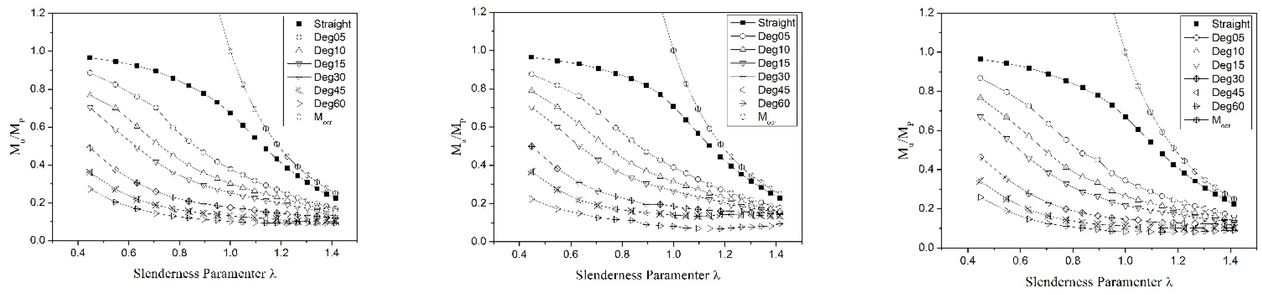
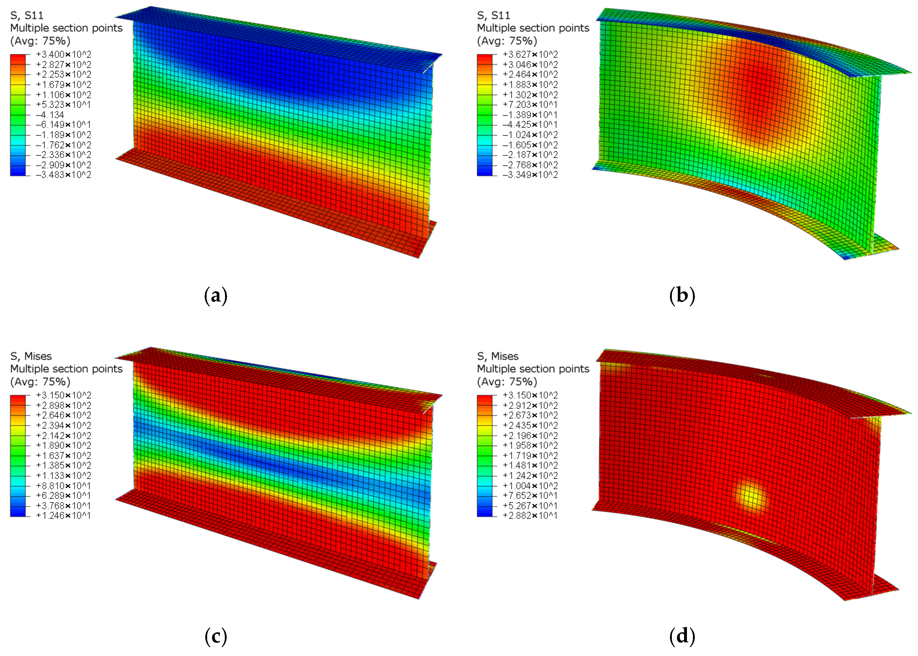
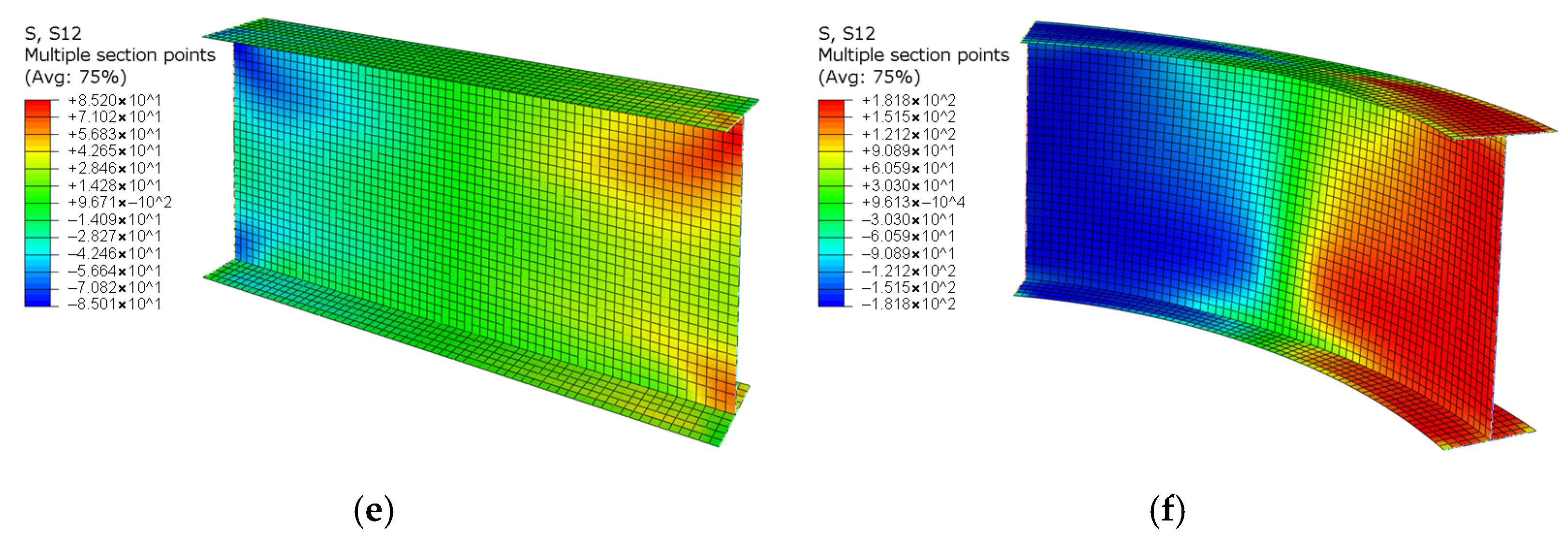
3.3. Analysis Results
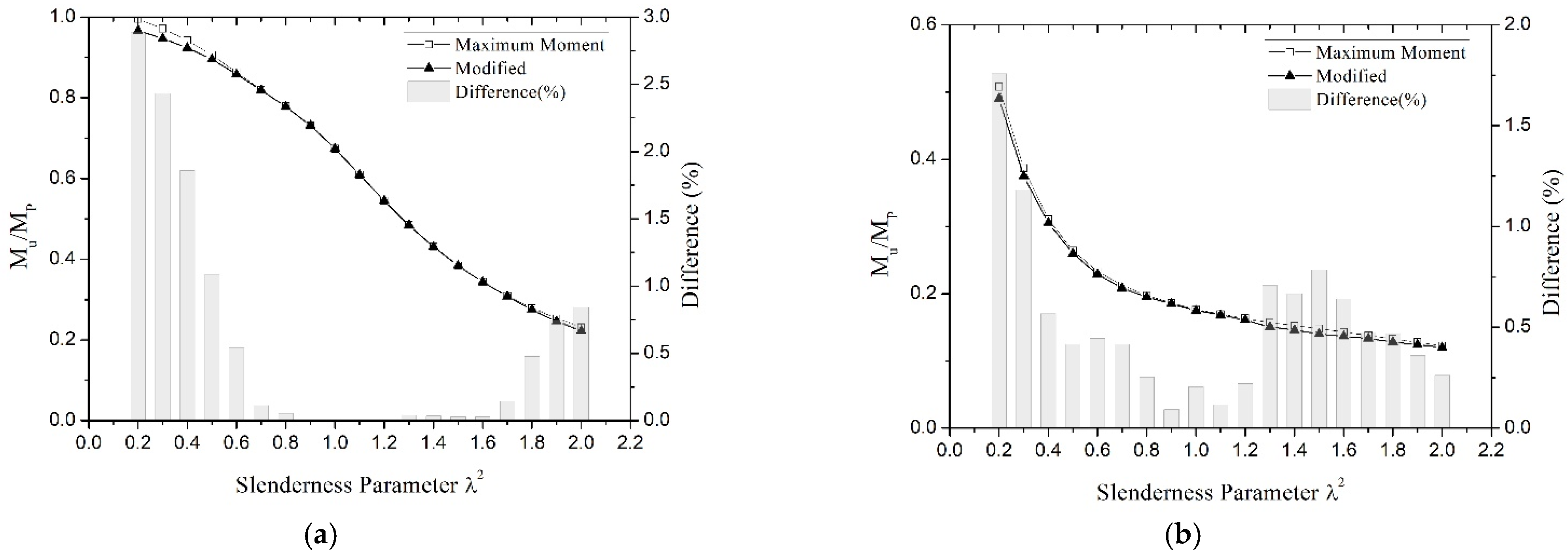
3.4. Ultimate Strength Equation
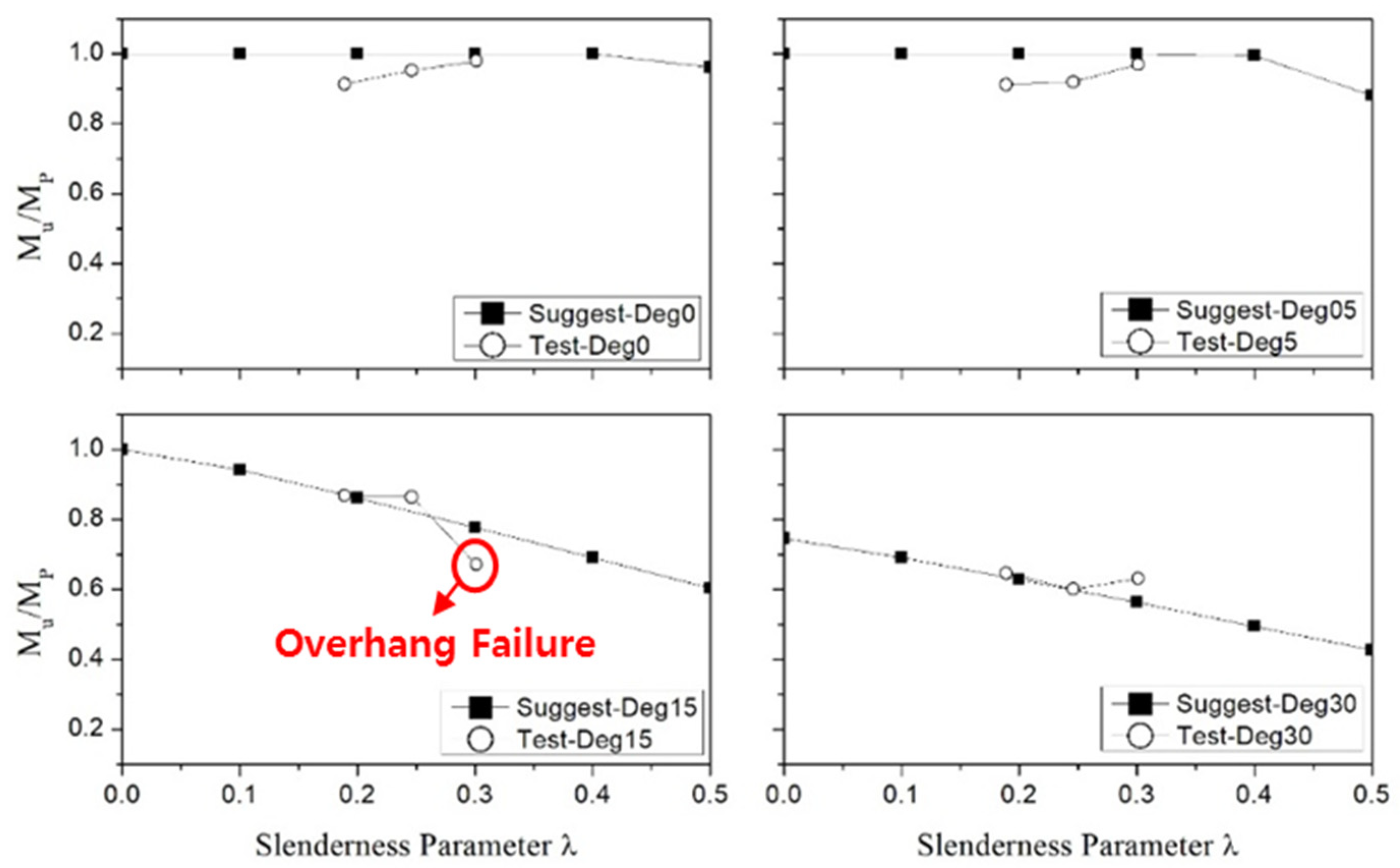
3.5. Verification of the Suggested Equation by FEA
4. Experimental Study
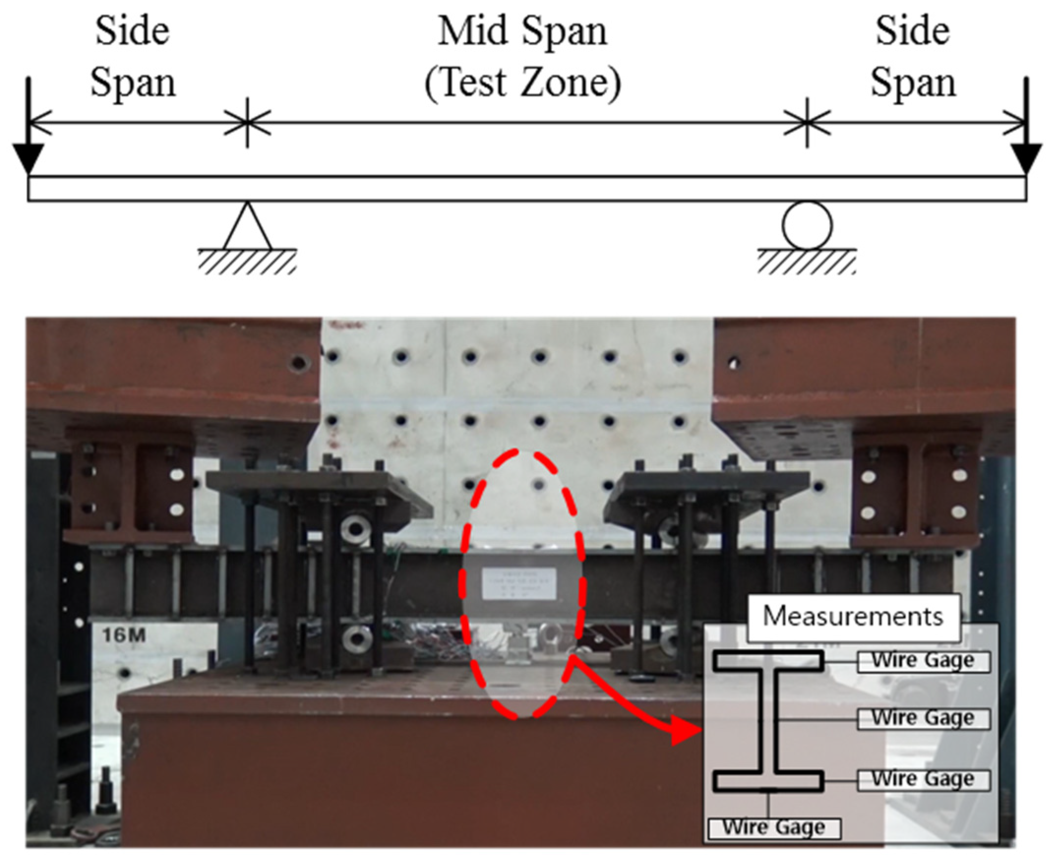
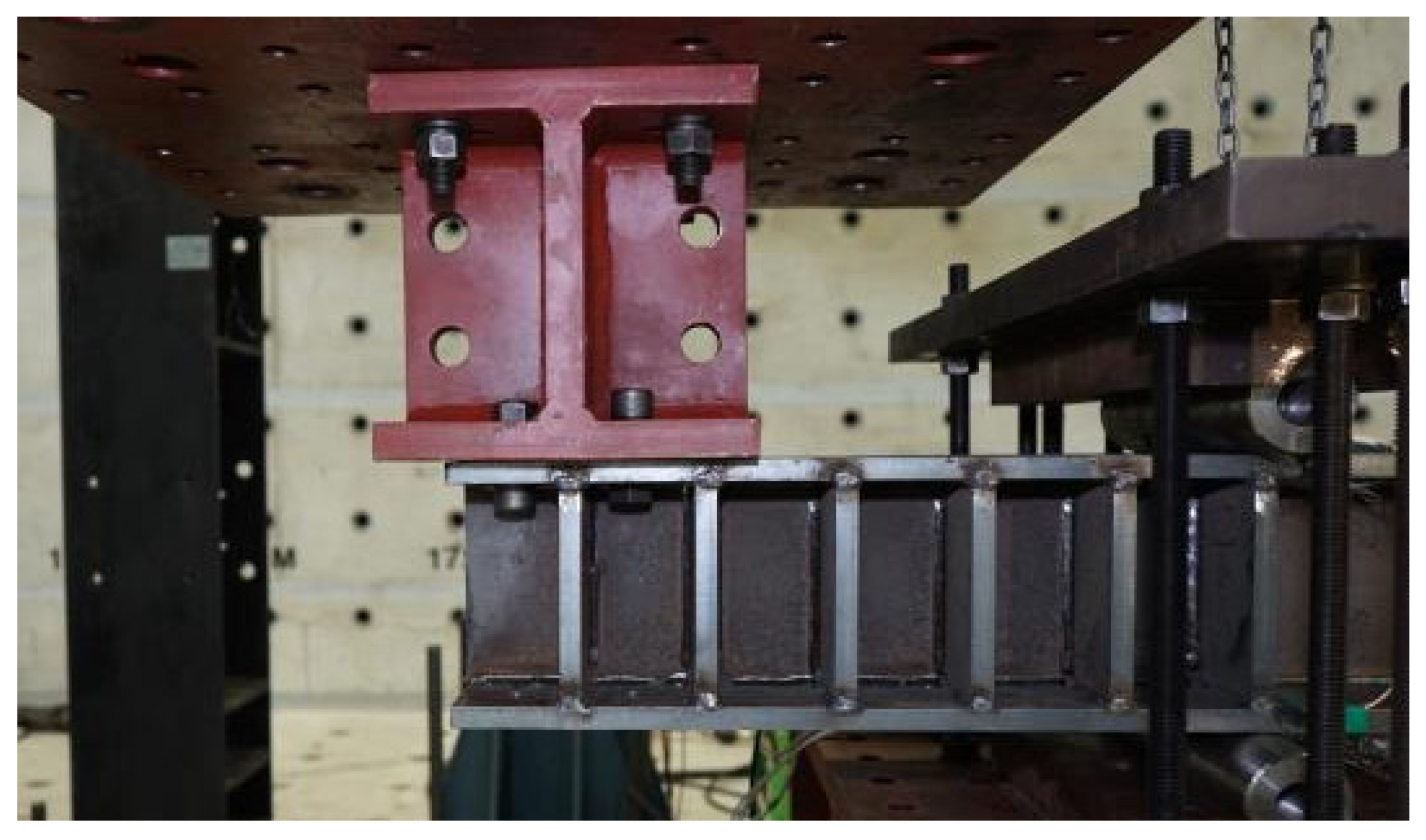
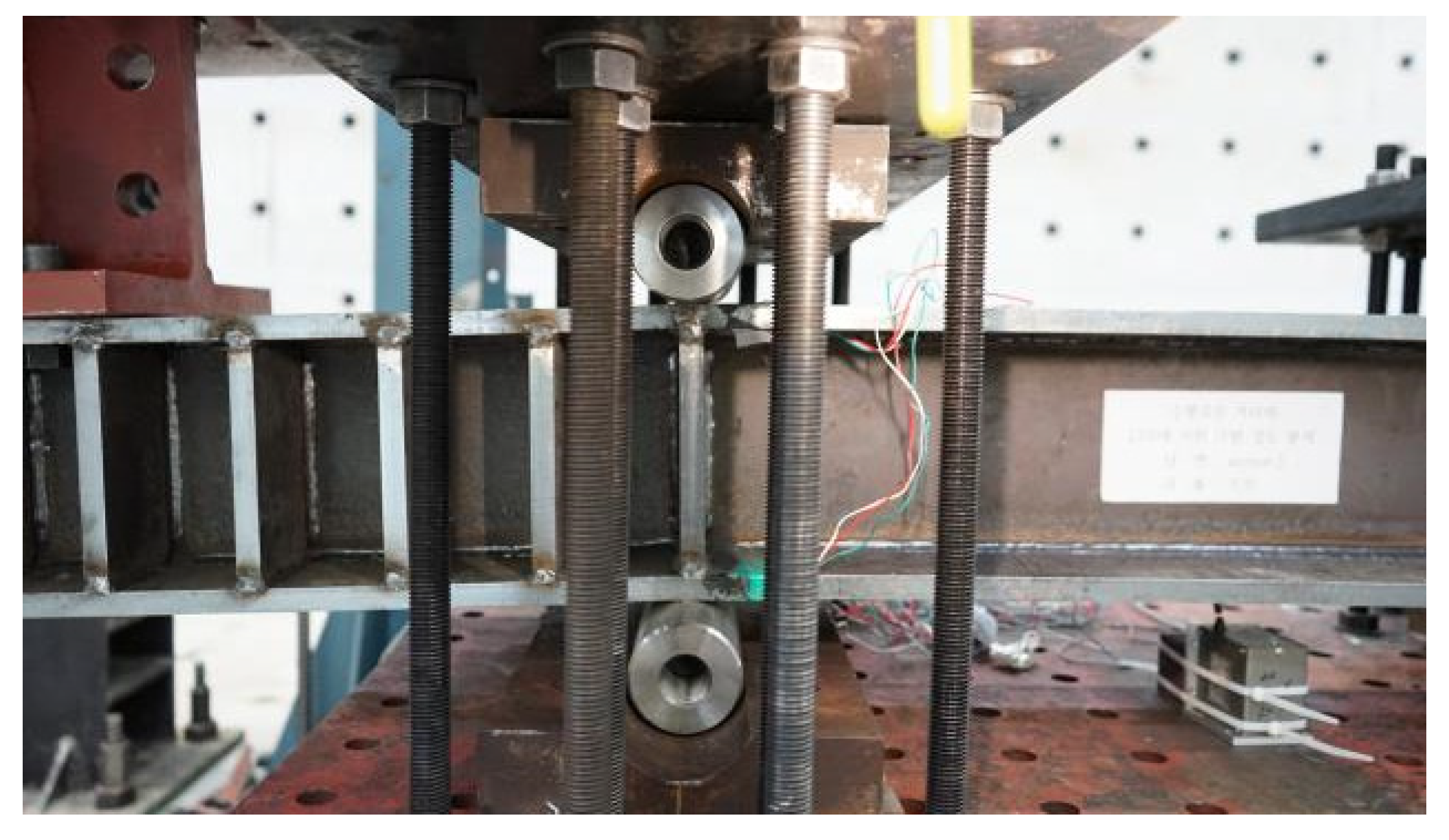
4.1. Test Setup and Measurements
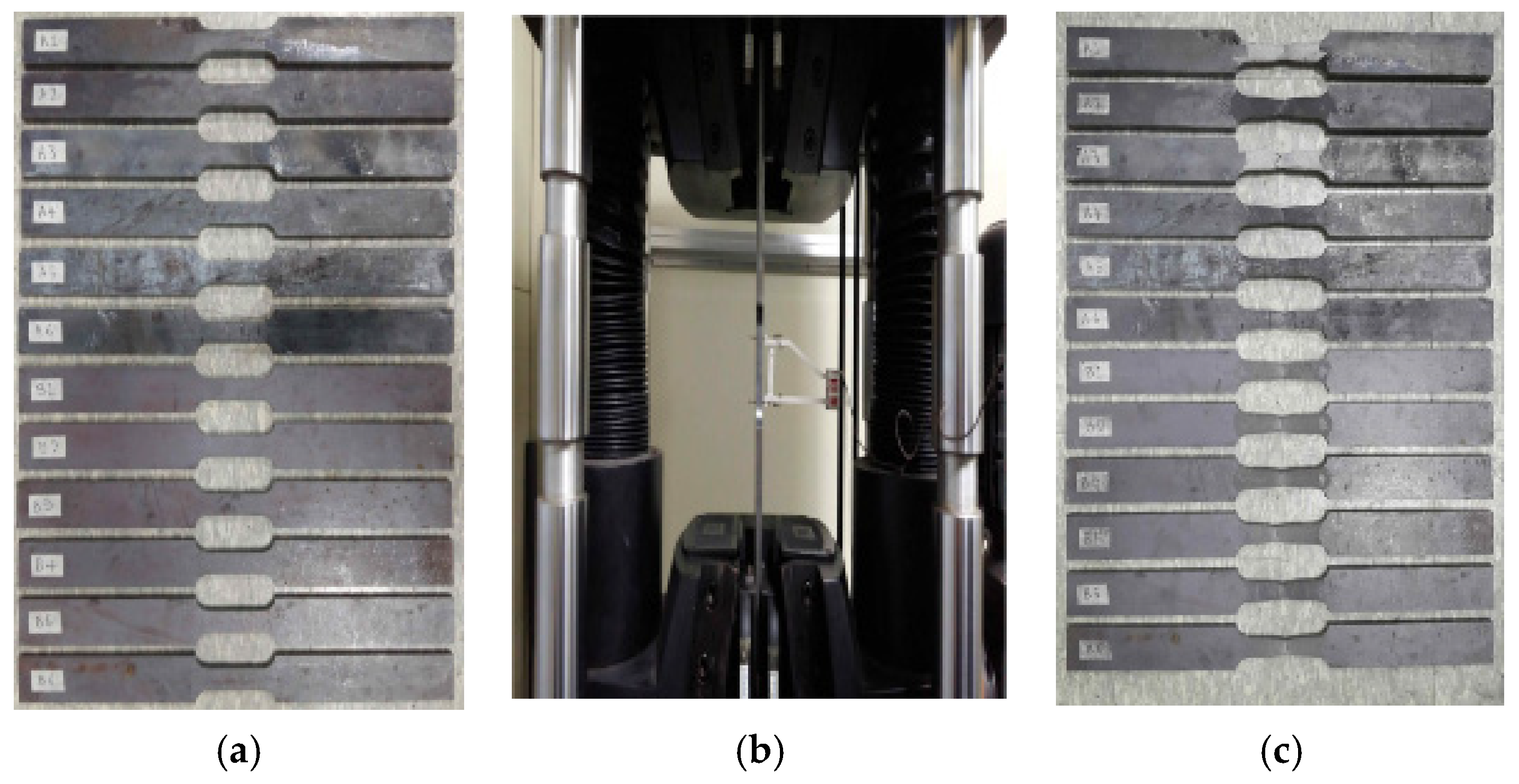
4.2. Material Test
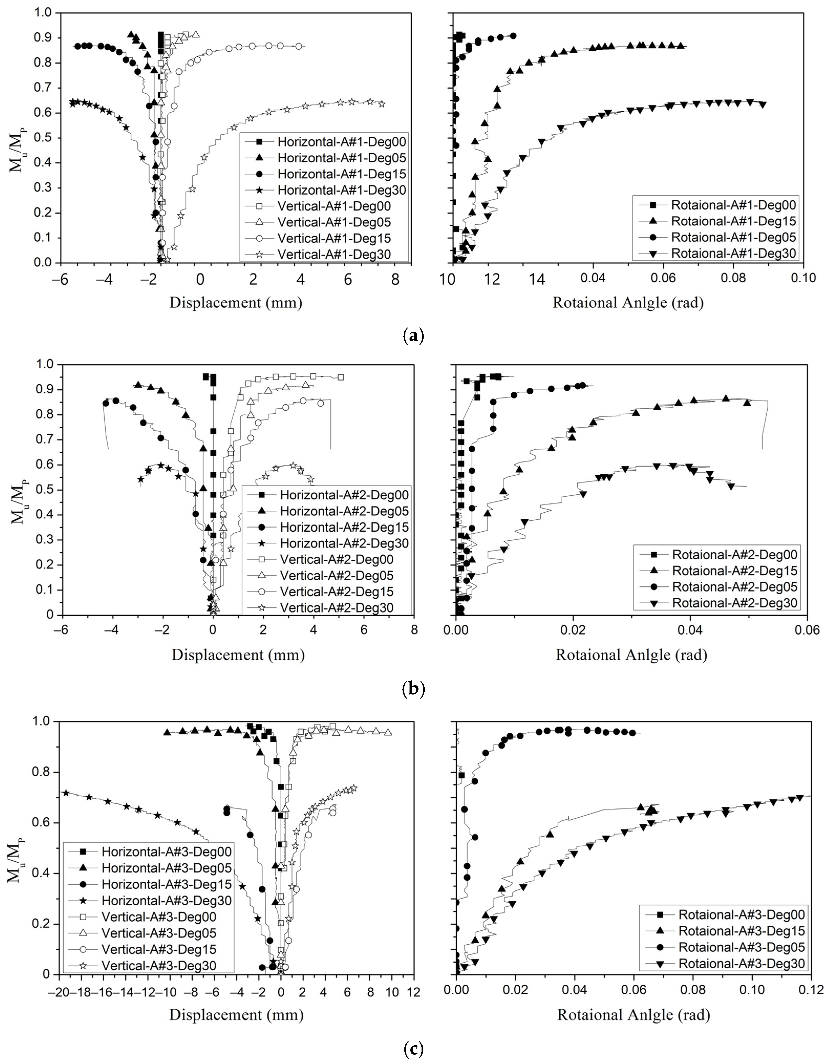
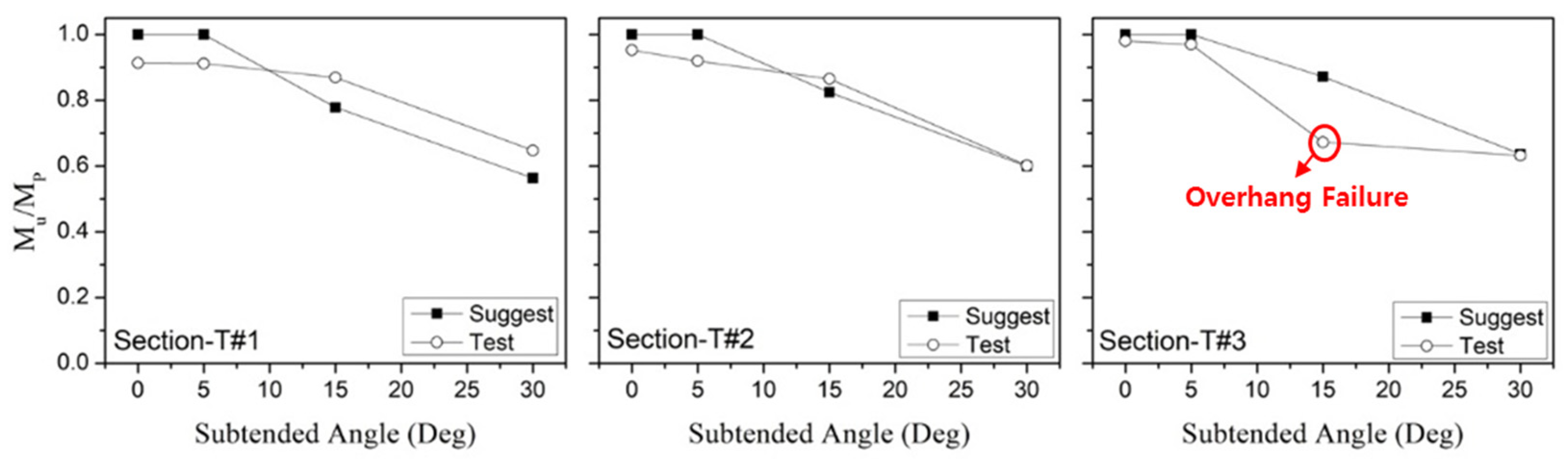
4.3. Test Results
5. Conclusions
Author Contributions
Funding
Institutional Review Board Statement
Informed Consent Statement
Data Availability Statement
Acknowledgments
Conflicts of Interest
References
- Fukumoto, Y.; Nishida, S. Ultimate Load Behavior of Curved I-Beams. J. Eng. Mech. Div. 1981, 107, 367–385. [Google Scholar] [CrossRef]
- Yoshida, H.; Maegawa, K. Ultimate Strength Analysis of Curved I-Beams. J. Eng. Mech. 1983, 109, 192–214. [Google Scholar] [CrossRef]
- Fujii, F.; Gong, S. Field Transfer Matrix for Nonlinear Curved Beams. J. Struct. Eng. 1988, 114, 675–692. [Google Scholar] [CrossRef]
- Liew, J.R.; Thevendran, V.; Shanmugam, N.; Tan, L. Behaviour and design of horizontally curved steel beams. J. Constr. Steel Res. 1995, 32, 37–67. [Google Scholar] [CrossRef]
- Kang, Y.J.; Yoo, C.H. Thin-Walled Curved Beams. I: Formulation of Nonlinear Equations. J. Eng. Mech. 1994, 120, 2072–2101. [Google Scholar] [CrossRef]
- Thin-Walled Curved Beams. II: Analytical Solutions for Buckling of Arches. J. Eng. Mech. 1994, 120. [Google Scholar] [CrossRef]
- Pi, Y.-L.; Trahair, N.S. Nonlinear Elastic Behavior of I-Beams Curved in Plan. J. Struct. Eng. 1997, 123, 1201–1209. [Google Scholar] [CrossRef]
- Pi, Y.-L.; Bradford, M.; Trahair, N.S. Inelastic Analysis and Behavior of Steel I-Beams Curved in Plan. J. Struct. Eng. 2000, 126, 772–779. [Google Scholar] [CrossRef]
- Pi, Y.-L.; Bradford, M. Strength Design of Steel I-Section Beams Curved in Plan. J. Struct. Eng. 2001, 127, 639–646. [Google Scholar] [CrossRef]
- Yoo, C.H.; Davidson, J.S. Yield Interaction Equations for Nominal Bending Strength of Curved I-Girders. J. Bridg. Eng. 1997, 2, 37–44. [Google Scholar] [CrossRef]
- Davidson, J.S.; Yoo, C.H. Evaluation of Strength Formulations for Horizontally Curved Flexural Members. J. Bridg. Eng. 2000, 5, 200–207. [Google Scholar] [CrossRef]
- Fasl, J.D.; Stith, J.C.; Helwig, T.A.; Schuh, A.; Farris, J.; Engelhardt, M.D.; Williamson, E.B.; Frank, K.H. Instrumentation of a Horizontally Curved Steel I-Girder Bridge during Construction. J. Struct. Eng. 2015, 141. [Google Scholar] [CrossRef]
- Amani, M.; Alinia, M. The flexural behavior of horizontally curved steel I-girder bridge systems and single-girders. J. Constr. Steel Res. 2016, 118, 145–155. [Google Scholar] [CrossRef]
- Issa-El-Khoury, G.; Linzell, D.G.; Geschwindner, L.F. Flexure–shear interaction influence on curved, plate girder web longitudinal stiffener placement. J. Constr. Steel Res. 2016, 120, 25–32. [Google Scholar] [CrossRef]
- Tsiptsis, I.N.; Sapountzakis, E.J. Generalized warping and distortional analysis of curved beams with isogeometric methods. Comput. Struct. 2017, 191, 33–50. [Google Scholar] [CrossRef]
- McElwain, B.A.; Laman, J.A. Experimental Verification of Horizontally Curved I-Girder Bridge Behavior. J. Bridg. Eng. 2000, 5, 284–292. [Google Scholar] [CrossRef]
- Shanmugam, N.; Mahendrakumar, M.; Thevendran, V. Ultimate load behaviour of horizontally curved plate girders. J. Constr. Steel Res. 2003, 59, 509–529. [Google Scholar] [CrossRef]
- Linzell, D.; Leon, R.T.; Zureick, A.H. Experimental and Analytical Studies of a Horizontally Curved Steel I-Girder Bridge during Erection. J. Bridg. Eng. 2004, 9, 521–530. [Google Scholar] [CrossRef]
- Thevendran, V.; Chen, S.; Shanmugam, N.; Liew, R. Nonlinear analysis of steel–concrete composite beams curved in plan. Finite Elements Anal. Des. 1999, 32, 125–139. [Google Scholar] [CrossRef]
- Thevendran, V.; Shanmugam, N.; Chen, S.; Liew, J. Experimental study on steel-concrete composite beams curved in plan. Eng. Struct. 2000, 22, 877–889. [Google Scholar] [CrossRef]
- Tan, E.; Uy, B. Experimental study on straight composite beams subjected to combined flexure and torsion. J. Constr. Steel Res. 2009, 65, 784–793. [Google Scholar] [CrossRef]
- Tan, E.; Uy, B. Experimental study on curved composite beams subjected to combined flexure and torsion. J. Constr. Steel Res. 2009, 65, 1855–1863. [Google Scholar] [CrossRef]
- Lee, K.; Davidson, J.S.; Choi, J.; Kang, Y. Ultimate strength of horizontally curved steel I-girders with equal end moments. Eng. Struct. 2017, 153, 17–31. [Google Scholar] [CrossRef]
- Galambos, T.V.; Ketter, R.L. Columns under Combined Bending and Thrust. Trans. Am. Soc. Civ. Eng. 1961, 126, 1–23. [Google Scholar] [CrossRef]
- Steel Construction Manual, 15th Ed. (Print) American Institute of Steel Construction. Available online: https://www.aisc.org/Steel-Construction-Manual-15th-Ed-Print (accessed on 25 June 2021).
- NCCI: Elastic Critical Moment for Lateral Torsional Buckling—PDF Free Download. Available online: https://docplayer.net/48950705-Ncci-elastic-critical-moment-for-lateral-torsional-buckling.html (accessed on 25 June 2021).
- AASHTO. Aashto Lrfd Bridge. Design Specifications, 8th ed.; American Association of State Highway and Transportation Officials: Washington, DC, USA, 2020. [Google Scholar]
- Ministry of Land, Transport and Maritime Affairs. LRFD Highway Bridge. Design Specifications; Ministry of Land, Transport and Maritime Affairs: Sejong, Korea, 2012. [Google Scholar]


| (Unit: mm) | Sec-A#1 | Sec-A#2 | Sec-A#3 |
|---|---|---|---|
| 320 | 594.614 | 1000 | |
| 80 | 204.470 | 250 | |
| 15 | 27.686 | 35 | |
| 12 | 20.320 | 25 |
| Slenderness Parameter () | with interval of 0.1 |
| Subtended Angle () | 0°, 5°, 10°, 30°, 45°, 60° |
| Dimension | Sec-V#1 | Sec-V#2 |
|---|---|---|
| (mm) | 400 | 500 |
| (mm) | 100 | 150 |
| (mm) | 20 | 30 |
| (mm) | 15 | 20 |
| (deg) | 15, 30, 40 | 13, 27, 36 |
| (Slender ratio) | 0.2, 0.5, 0.8, 1.0, 1.2, 1.4 | |
| Dimension | Sec-T#1 | Sec-T#2 | Sec-T#3 |
|---|---|---|---|
| (mm) | 202 | 202 | 204 |
| (mm) | 219.8 | 171.2 | 142.16 |
| (mm) | 18 | 18 | 16 |
| (mm) | 10 | 12 | 12 |
| (Slender ratio) | 0.189 | 0.246 | 0.301 |
| (deg) | 0, 5, 15, 30 | ||
| Thickness | Elastic Modulus | Average Elastic Modulus | Yield Stress | Average Yield Stress | Ultimate Stress | Average Ultimate Stress |
|---|---|---|---|---|---|---|
| (mm) | (GPa) | (GPa) | (MPa) | (MPa) | (MPa) | (MPa) |
| 17.9 | 206.1 | 205.9 | 344.6 | 341.8 | 549.5 | 550.5 |
| 17.9 | 205.8 | 339.4 | 552.9 | |||
| 18 | 205.9 | 341.5 | 549.2 | |||
| 16.1 | 205.7 | 206.0 | 345.8 | 344.1 | 557.2 | 554 |
| 16.3 | 206.1 | 341.8 | 546.8 | |||
| 15.9 | 206.1 | 344.8 | 558 | |||
| 11.8 | 206.2 | 206.0 | 343.7 | 345.2 | 531 | 530.2 |
| 11.8 | 206.1 | 346.6 | 530.6 | |||
| 11.7 | 205.8 | 345.2 | 528.9 | |||
| 9.8 | 206.2 | 206.1 | 370.8 | 370.3 | 531.2 | 527.3 |
| 9.9 | 206.1 | 372.3 | 522.2 | |||
| 9.8 | 205.9 | 367.7 | 528.4 | |||
| Average | 206.0 | 350.35 | 540.5 | |||
Publisher’s Note: MDPI stays neutral with regard to jurisdictional claims in published maps and institutional affiliations. |
© 2021 by the authors. Licensee MDPI, Basel, Switzerland. This article is an open access article distributed under the terms and conditions of the Creative Commons Attribution (CC BY) license (https://creativecommons.org/licenses/by/4.0/).
Share and Cite
Lim, J.; Kang, Y.-J.; Lee, J.; Kim, S.; Lee, K. Experimental and Analytical Study of Horizontally Curved I-Girders Subjected to Equal End Moments. Metals 2021, 11, 1132. https://doi.org/10.3390/met11071132
Lim J, Kang Y-J, Lee J, Kim S, Lee K. Experimental and Analytical Study of Horizontally Curved I-Girders Subjected to Equal End Moments. Metals. 2021; 11(7):1132. https://doi.org/10.3390/met11071132
Chicago/Turabian StyleLim, Jeonghyeon, Young-Jong Kang, Jeonghwa Lee, Seungjun Kim, and Keesei Lee. 2021. "Experimental and Analytical Study of Horizontally Curved I-Girders Subjected to Equal End Moments" Metals 11, no. 7: 1132. https://doi.org/10.3390/met11071132