Article

Efficiency and Sustainability Analysis of the Repair and Maintenance Operations of UNS M11917 Magnesium Alloy Parts of the Aeronautical Industry Made by Intermittent Facing

by
Jacobo Fernández
1,
Eva María Rubio
1,*,
Diego Carou
2 and
Raquel María Lorente-Pedreille
3
1
Department of Manufacturing Engineering, UNED, St/Juan del Rosal, 12, E28040 Madrid, Spain
2
Departamento de Deseño na Enxeñaría, Campus As Lagoas, Universidade de Vigo, E32004 Ourense, Spain
3
Mechanical Engineering Department, ICAI, Comillas Pontifical University, Alberto Aguilera 25, E28015 Madrid, Spain
*
Author to whom correspondence should be addressed.
Metals 2021, 11(7), 1035; https://doi.org/10.3390/met11071035
Submission received: 2 June 2021 / Revised: 21 June 2021 / Accepted: 24 June 2021 / Published: 28 June 2021
(This article belongs to the Special Issue Sustainable Manufacturing of Light Alloys)

Abstract

:
This paper analyzes the efficiency and sustainability of facing operations that are required within maintenance operations in the aeronautical industry. Due to the elevated cost and environmental impact of such processes, reducing the operating time while repairing parts is required. In this work, an experimental study of intermittent facing carried out on a magnesium alloy rod was developed. The experiment resembles real repair and maintenance machining operations, where an intermittent facing represents a more realistic scenario and where the results obtained in continuous turning studies are not always applicable. The work was performed with different cooling and lubrication systems and various cutting conditions, also considering the size of the interruption to analyze their impact in the surface roughness. To this end, surface finished in different measuring zones was studied. The aims of the study are to get a better understanding of the intermittent facing process in magnesium alloys typically employed in aeronautical applications and find the most efficient cutting parameters to obtain an improved surface under the safest and most environmentally respectful conditions.

1. Introduction

In recent times, several industries showed a great interest in using lightweight materials, mainly for economic and ecological reasons [1,2]. Specially, the use of light materials in the aeronautical and automotive industry became a key factor for improvement [3,4]. Magnesium and its alloys are one of the lightest structural materials, providing advantages such as excellent strength to weight ratio, specific stiffness, and very good machinability. These characteristics turned it into a material with an excellent perspective for the future [5].
The components employed in the aeronautical industry must meet very strict standards, not only when first designed and produced, but they also must accomplish quite sever requisites after processing. Repair and maintenance operations are extremely important in the aeronautical sector as without them there is a risk of accidents with serious consequences [6,7]. For this reason, the corresponding authorities tightened the standards for carrying out this kind of operations [8,9]. Consequently, repair and maintenance operations in the aeronautics sector must adhere to very strict technical requirements, and in recent years, also environmental requisites, resulting in higher costs for these operations, both direct and indirect. As there are no spare parts in stock, while the repair or maintenance activities are carried out, the aircraft remains out of service, with the associated losses that this entails. Therefore, repair and maintenance operations must be developed in the most efficient and sustainable way and in the shortest possible time [10].
Most investigations with magnesium are only focused on continuous machining processes [11] since the bibliography related to intermittent facing is very limited. In practice, parts in the aeronautical sector often have complex geometries, with surfaces interrupted by holes, lubrication channels, grooves, and spaces for the placement of auxiliary elements, cables, etc. Due to this, intermittent machining represents is a more accurate representation of real geometries than continuous machining. Consequently, it is more adequate to employ rods with a geometry that includes interruptions to study the repairing processes in the aeronautical sector. [12,13]. The investigation hereinafter described studies the performance when facing magnesium alloy parts under intermittent machining conditions, considering both the particularities for this specific material and operating conditions. Additionally, environmental restraints are to be considered.
Despite its great performance for aeronautical components, due to its light weight and good mechanical characteristics, magnesium has some disadvantages that must be examined. To start with, magnesium has a higher cost in comparison to its main competitor, aluminum, and therefore, manufacturing plays a key role to make it economically competitive [14]. Some recent investigations do even focus on how to obtain new magnesium alloys by recycling magnesium swarf [15]; other research lines aim to improve the originally low corrosion resistance of magnesium alloys by studying superficial treatments and coatings [16,17], as it affects its total service life.
An important drawback to take into consideration when machining magnesium is that its ignition temperature, around 460–480 °C, occurs below its melting point, of 650 °C. Consequently, it is an easily flammable material that can cause chips to ignite during machining processes [18,19].
Maximum temperatures in machining processes are strongly linked with cutting speed, feed rate, and depth of cut [5,20,21], so special attention must be paid to defining these three parameters when turning magnesium. Specifically, cutting speed must be limited during the experiment to reduce fire hazard.
Another risk must be considered when it comes to water-based cooling systems due to the existing reactivity between water and magnesium. The use of water-based coolants to reduce the temperature in the cutting area is very dangerous due to water reacting with magnesium, forming hydrogen atmospheres that are flammable and potentially explosive [22,23].
Even so, magnesium can be machined at high speed with good results if some precautions to avoid high temperatures are taken [24]. The high conductivity of magnesium allows to evacuate most of the heat generated during machining through the chips, which is an advantage to reduce temperature [25]. The temperature range can also be maintained in a safe level if we avoid prolonged machining processes [26].
It is also possible to keep low temperatures in magnesium machining using low performance cutting conditions (low cutting speeds, low depth of cut, low feed rate and a short machining time) as in the experiments [21,27].
Regarding the problems associated with cooling systems, it is also possible to carry out machining processes of magnesium in dry conditions without ignition risk. The magnesium was machined in dry conditions in several experiments with very good results, as shown in [20,21,27,28,29,30,31]. Dry machining is very advantageous for simplifying the machining operation, reducing costs, and removing any health and environmental problem that other cooling systems can cause. It is one of the most sustainable options to carry out a machining process [28].
Apart from all the forethoughts when manufacturing magnesium alloys, some issues regarding intermittent facing must also be considered. Intermittent cutting is the more common situation when machining aeronautical components: typically, the geometry of the parts includes several variations such as holes, drills, or grooves that cause interruptions in the face to be machined. The constant shocks between the piece and the cutting tool produce thermal cycles due to the continuous lapses of cutting and interruption time. This leads to a machining process with its own particularities that requires further analysis [32].
In addition, the progress of the temperatures in intermittent machining are different from continuous machining, due to these cycles of raising temperatures during cutting lapse and cooling effect during noncutting time. Consequently, the temperatures reached are lower than those in the equivalent continuous machining process [32,33,34]. The continuous impacts between tool and piece, together with the thermal cycles that are generated, make also a more severe case for the tool. Therefore, it should be conveniently selected to carry out a turning operation successfully. For example, in the experiment carried out by Kitawa et al. [35], the maximum temperature reached in continuous turning was 15% greater than the one attained during intermittent turning. In the experiment conducted by Carou et al. [21], a finish turning is developed in a magnesium piece with 3 different conditions (continuous turning and interrupted turning with 15 and 30 mm slots). One of the most interesting conclusions is that for the selected conditions, temperatures vary accordingly to the interruption size, being higher for the smaller interruption.
In the same way, it is expected that surface roughness results in intermittent machining will be different to the equivalents carried out under continuous conditions [36]. Surface roughness is one of the most widespread characteristics to measure and analyze the result of a machining process, both in the industry and experimental studies. It was extensively considered as a parameter to measure the quality in a piece [21,31,37]. The complexity in predicting and studying the surface roughness is due to the many factors that may have influence in the surface roughness of a machined piece [31]. In this regard, numerous studies of intermittent turning [21] and facing [27,31] concluded that feed rate is, by far, the most influential factor in the surface roughness result: an increase in the feed rate will generate an increase in surface roughness [21,27,28].
Additionally, it is also possible to say that interruptions will have an influence in the surface roughness. In the experimental study [36], the results showed that surface finish worsens when the quantity of interruptions increase. On the opposite, in the experimental study carried out by Liang et al. [38] concluded that the surface roughness found in the intermittent machining is better than in the continuous machining. Consequently, continuous machining results cannot be generally used or directly transferred [39,40].
The large number of studies carried out and the variety of results obtained point out the huge quantity of phenomenon associated with the cutting process and the surface roughness achieved, which has led to the development of some models to try to predict the surface finish. However, general expressions to predict surface roughness cannot explain the actual machining process on which will exist some differences in comparation with the theoretical result obtained [28].
The machining conditions, the material of the piece, the tool used, and the parameters selected make it very difficult to set a clear conclusion or general rules for the surface roughness result, which forces the need to carry out experimental studies to evaluate the surface roughness under specific conditions.
This research provides a better understanding of the special machining conditions for this special magnesium alloy together with the particularities present in repair and maintenance operations, where intermittent machining represents a more realistic case. The results obtained may offer a suitable and profitable solution in economic terms, giving the chance to enlarge the life of the components. This work investigates magnesium intermittent facing process, aiming to find the most suitable and efficient cutting parameters under the most demanding industrial requirements. Additionally, the influence of different cooling and lubrication technologies in combination with the cutting paraments by means of the surface roughness results were studied.
Thanks to the contributions within this research, the use of these operations for reparation of high-cost magnesium parts may be developed in an efficient way, offering a suitable and profitable solution in economic terms and making it possible to enlarge the life of the components.

2. Methodology

The experiment under study focuses on magnesium machining through intermittent facing, evaluating the cutting parameters and cooling/lubrication systems considering their influence on the workpiece surface roughness results.
The methodology used is based on statistical techniques that allow us to find the influence and correlations between the cutting parameters and the response variable; thus, we can identify the factors that have the greatest influence. Only by selecting the correct cutting paraments can an efficient machining process be performed.
Surface roughness is the response variable selected in several experiments [21,27,28,31,37] to evaluate and measure the quality of a machined workpiece. In this case, surface roughness was selected to measure the results of the study to allow comparison with the obtained values with other experiments; besides, it is a common manufacturing requirement in the industry. Specifically, the arithmetical mean deviation, Ra, was chosen; it provides the average roughness as an arithmetical mean of the different roughness along an assessed profile.
The need to carry out an experiment comes from the difficulty and complexity of knowing and predicting the surface roughness in a machining process. Two of the main causes for this come from [37]:
  • The wide range of influential factors and their different achievable levels.
  • The specific particularities of each case and piece that makes each process unique and too complex for applying general rules.
The number of factors that could impact on the surface roughness is very high, and some of them are [37]: the cutting tool, cooling/lubricating system, depth of cut, feed rate, cutting speed, workpiece properties, and phenomena associated with the cutting process. The experiments described in this investigation were carried out considering a selection of the most influential factors according to the aforementioned experiments. In addition, the different levels of each factor were selected to get a representative study giving the maximum amount of information at a reasonable cost:
  • This investigation aims to emulate repair and maintenance machining operations, so a low depth of cut was considered to remain within the narrow tolerances used in the industry [21,31]. A depth of cut below 0.25 mm will be considered for the experiment. Keeping the depth of cut in a small value will also help to maintain a low cutting temperature [41], which will be also favorable to stay far from the magnesium ignition temperature.
  • Regarding the refrigeration and lubrication systems (c), under repair and maintenance conditions, there is no need to reduce the temperature in the cutting zone for safety reasons (ignition risk at temperatures near 450 °C). Moreover, the risk of magnesium chips ignition will be reduced by controlling the cutting speed and the depth of cut, allowing us to keep the machining temperature low. The risk of generating an explosive hydrogen atmosphere because of reactivity between magnesium and water particles will be completely avoided using alternative nonwater-based cooling and lubrication techniques like MQL (Minimum Quantity Lubrication), CCA (Cold Compressed Air), and dry machining.
  • The cutting tool and its coating greatly influence the finish quality of the workpiece. This was verified in numerous experiments: [21,29,31,42]. In this case, the same type of cutting tools from the magnesium facing study of [31] and the magnesium turning study of [11] will be used with the purpose of making them comparable.
  • Among other influential factors, feed rate (f) was clearly identified in many studies as the most influential factor in the surface roughness [21,23,27,31]. This experiment seeks to obtain surface roughness values in the range commonly required in the aeronautical industry, 0.8 μm < Ra < 1.6 μm [43]. With that purpose, three different levels will be considered for this factor.
  • Spindle speed, related to cutting speed, is another influential factor of the surface roughness. However, its expected effect is much smaller in comparison with the feed rate. Specifically, only 1–2% of the surface roughness variability is expected, according to previous studies [21,31]. The maximum cutting speed achieved in other investigations on magnesium alloys under dry conditions will not be exceeded in this experiment.
Apart from the facing parameters described above, the interruptions in the part geometry may possibly affect the results. Considering that cutting speed in facing vary linearly with the cutting radius, the roughness measuring zone may affect the surface roughness result. The surface geometry of the machining face has some interruptions (which are further addressed below), allowing us to distinguish and evaluate up to eight different levels for the measuring zones.
The measuring zones were divided according to the following criteria:
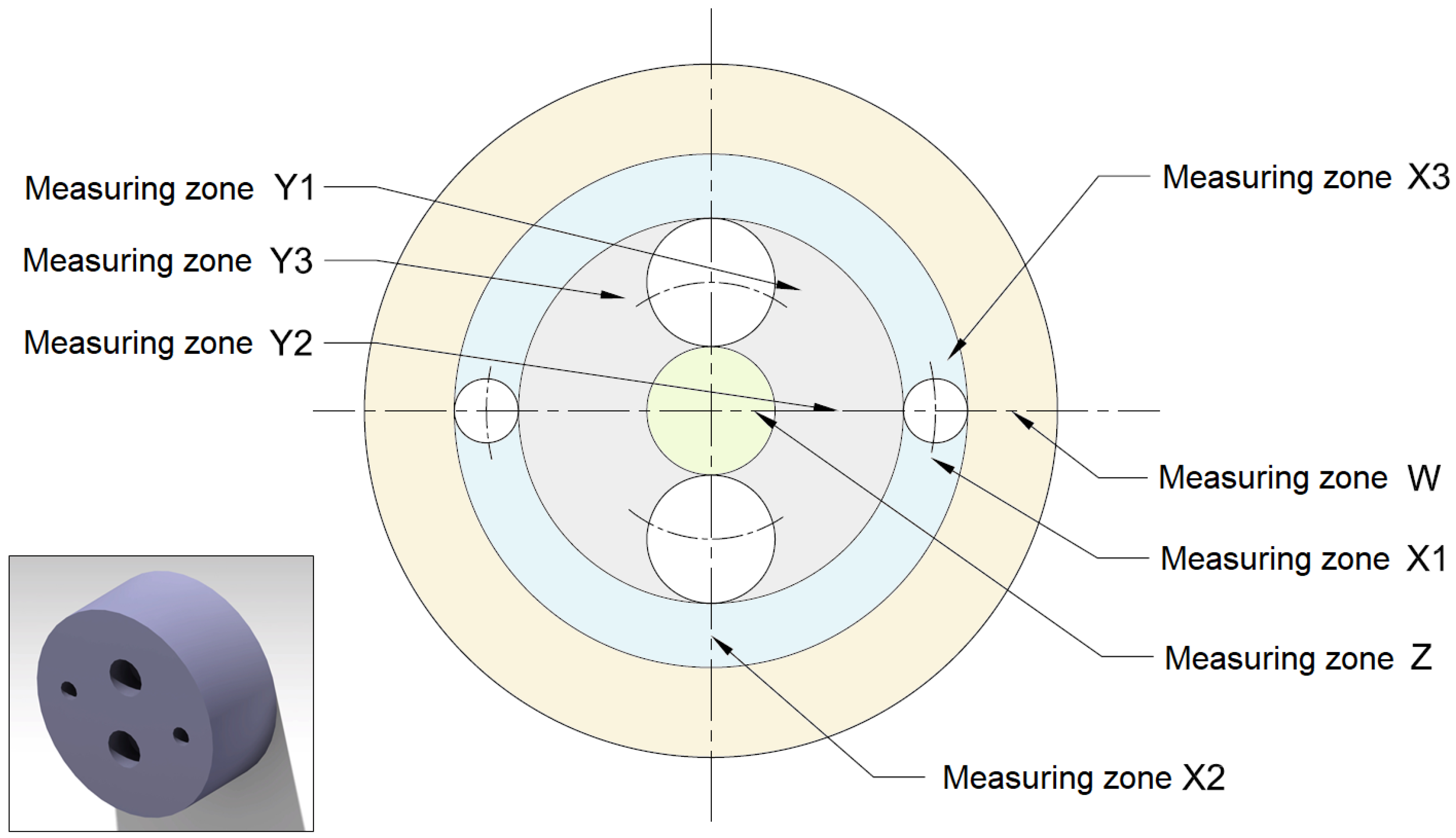
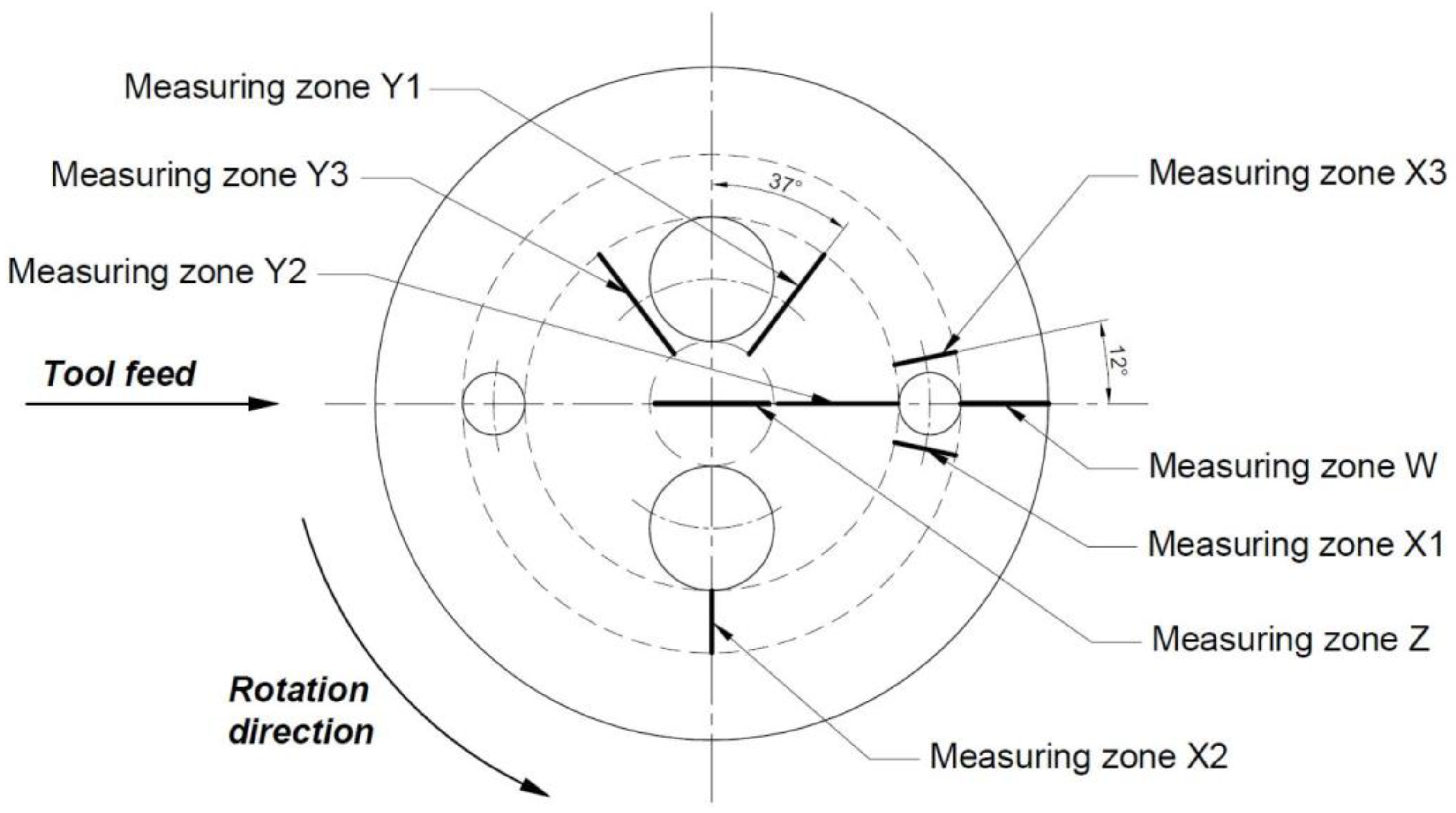
  • One measurement on the areas obtained by means of continuous turning.
  • Three different measurements on the areas next to the interruptions: two measures close to the interruptions (just before and after) and one additional measurement in the area further away from these interruptions.
Various studies [21,44] show how intermittent machining and the size of the interruption have an influence on the results of surface roughness of the workpiece. For this reason, it is established a geometry that allows to study four different types of zones with different interruptions in the machining face (as illustrated in Figure 1). Regarding the workpiece design, the geometry studied in the experiment by Carou et al. [21] was taken as a reference, although several variations were made to get more information from the experiment. In the workpiece, 4 blind holes with 3 mm depth were machined on the face of the round bar with different sizes and positions to generate different cutting conditions and interruptions.
The geometry of the machining face is shown in Figure 2. Four areas considering the machining conditions can be defined:
  • Without interruptions (continuous turning)—Ring W, colored in yellow. Continuous facing (no interruptions). Annular area, 14 mm wide, where a noninterrupted turning is conducted.
  • Slight interruption—Ring X, colored in blue. Intermittent facing. Annular area, 10 mm wide, where two 3 mm depth holes produce a slight interrupted turning condition.
  • Moderate interruption—Ring Y, colored in grey. Intermittent facing. Annular area, 20 mm wide, right after the previous zone, where there are two 3 mm depth opposite holes, producing a more severe interrupted turning condition than previous one.
  • Not interrupted (after intermittent machining)—Ring Z, colored in green. Continuous facing (After interruptions). Circular area of 10 mm of radio where a noninterrupted turning is conducted just after the machining tool has endured an interrupted machining process.
In this manner, it will be possible to assess both the influence of the interruptions on the machining results and the size of the interruption.
To analyze the influence of the factors described above and its levels, a study with minimal experimentation was completed with the aim of conducting practical and efficient research. A full factorial design considering all possible combinations between the factors feed rate, f, and cooling and lubrications system, c, was selected. As for the other parameters, only one level was considered. Finally, a group of 9 different trials were developed. Regarding the measuring zone, 8 surface roughness measurements were obtained in different areas of the machined face for each trial, with leads to total of 72 Ra measurements for 9 trials.
To guarantee the reliability of the results and verify the repeatability of the obtained data, the trials were duplicated. Therefore, two series of trials were developed, each set as group of trial 1 and 2. Each individual trial was defined by 2 numbers, the first one for the series/group (1 or 2) and the second one for their order in that group. In addition, to avoid the influence of uncontrollable factors, the experimental trials were carried out in random order, resulting in a total of 18 trials and 144 measurements.
From the completion of the described plan, a large data set of the response variable (surface roughness) was obtained. In the next stage of the process, a statistical analysis was developed to evaluate the initial hypothesis about the behavior of the different factors and their influence in the response variable.
A preliminary analysis was conducted to study the repeatability of the obtained data during the trials with the aim to detect results out of the expected range and to identify the origin of the possible disturbance. In second place, a comparative analysis between different measuring zones of the machined face was developed with the purpose of defining whether there is any influence between the interruptions and the surface roughness.
Based on these preliminary results, a more exhaustive analysis will be carried out for assessing, independently and combined, the influence of each factor and its levels on the surface roughness result.
The measurement results and their analysis will allow to get objective conclusions on the main studied points:
  • To determine the influence of the geometrical interruptions in the surface roughness.
  • To obtain conclusions of the most suitable cutting conditions to carry out an efficient and sustainable repair and maintenance machining operations.
Based on these results, recommended ranges are defined for each factor, establishing practical recommendations that can be used in future studies.

3. Application

The facing operation is carried out on a cylindrical specimen of UNS M11917 (AZ91D-F) magnesium alloy with 108 mm diameter and 35 mm length. This alloy is a very common pressure die casting of Magnesium-Aluminum-Zinc, with an approximate mass percentage of 9% of Al and 1% of Zn.
The selection of the machining tool was made considering the tools used in similar studies [21,31,45,46,47] so as to compare the results. In this case, only one of them was selected according to the results obtained in the magnesium facing experiment [31], HX tool. It is an uncoated machining tool, tungsten carbide base with cobalt (WC-Co), and it is a specific tool for no-ferrous materials. The tool is named according to ISO 1832:2012 in Figure 3.
Photographs of the cutting tools were taken after each test with a profile projector Tesa Visio. The facing operation on the magnesium bar is carried out in a parallel lathe model Pinacho L-1/200.
Right after each test, surface roughness measurement is done on the workpiece using a roughness meter Mitutoyo Surftest SJ 401. Concretely, the information of the measurement and filtering is the next one: Gauss filter, evaluation length of 8 mm, cutoff length of 2.5 mm, and radius of the stylus of 2 mm.
As described in the design of the experiment and its methodology, for each independent trial considered, the surface roughness was measured in 8 different areas of the machined face of the piece. There was a maximum of 3 measuring areas on each annular area W, X, Y, and Z:
  • Measuring zone 1: the line just after the interruption.
  • Measuring zone 2: the equidistant line between interruptions.
  • Measuring zone 3: the line just before the interruption.
The measuring lines after and before the holes are placed to an approximate distance of 2.5 mm from the interruption border. Considering that mentioned above, it is possible to generate the following 8 measuring zones explained in Figure 4: W, X1, X2, X3, Y1, Y2, Y3, and Z.
MQL Accu-Lube Microlubrification System (Accu-Lube Manufacturing GmbH, Maulbronn, Germany) with a frequency generator and CCA system Vortex tube model 610 (ITW Vortec and Paxton Products, Cincinnati, OH, USA) are used as a lubrication and cooling system, respectively (as illustrated in Figure 5). Due to the risk of magnesium ignition, a proper lubrication fluid was selected for MQL system. Fluid r.rhenus Nor SSL FA/1031011 (Rhenus Lub S.A., San Sebastián, Spain) is specially recommended of magnesium machining. This cutting lubricant is based on natural fatty acid esters and is free of mineral oils and chlorine.
Some investigations showed the existing relation between different lubrication regimes and the surface roughness. Based on the results obtained in [48,49], new analysis could be added to the investigation described within this paper, and so are considered as a future research line.
MQL system characteristics:
  • Maximum lubrication: 4.5 mL/min
  • Minimum lubrication: 0.9 mL/min
  • Pressure: 6 bar
CCA system characteristics:
  • Lowest air temperature reached: −18 °C
As it was explained in the previous section, the following specific values and levels of each factor of the experiment are to be selected (as illustrated in Table 1):
  • Depth of cut, d: it is set to 0.03 mm which is the minimum stable value achievable by the lathe of the laboratory. Notably, repair and maintenance operations are carried out under very low depth of cut values (low performance cutting conditions) to fulfil the design dimensional tolerance after the machining process.
  • Cooling and lubrication system, c: in addition to the dry machining, it is selected a flow for MQL system of 4.5 mL/min, which is the maximum flow available in the device. The purpose is allowing the maximum influence of the lubrication system in a machining operation of reduced time. Regarding the cold compressed air system, it is selected at the lowest temperature allowed by the CCA equipment, −18 °C.
  • Feed rate, f: feed rate was identified as the most relevant factor regarding its influence in surface roughness. Three different levels were studied. Feed rate values of 0.1, 0.14, and 0.2 mm/rev were selected to avoid going much further from 100 mm/min feed used in repair and maintenance works.
  • Spindle speed, s: in this test, maximum cutting speed achieved in other magnesium alloys dry machining experiments will not be exceeded. It is set at one level for spindle speed of 925 rev/min.

4. Discussion of Results

The first results obtained in the experiment are shown in Table 2. Although the trials were carried out in random order so that the effect of uncontrolled influences could be avoided, adding more reliability to the results, the values shown in Table 2 are ordered, showing the average value for the pair of counterpart’s trials carried out with the same cutting conditions (among the group of trials 1 and 2). The factors that were kept constant (spindle speed, tool, depth of cut) are not shown.
For a better understanding, those results with higher surface roughness are highlighted in a darker color than those with smaller Ra values. Moreover, those values exceeding the upper limit for the admissible surface roughness range in aeronautical industry (0.8 µm < Ra < 1.6 µm) are surrounded with a red line.
Based on the data shown in Table 2, for a certain feed rate f, the type of cooling system does not have such a big impact on the final Ra. Considering that the feed rate was the most influential factor in other similar experiments, it is possible to make a first analysis approach and get a very first conclusion, confirming the correlation between feed rate, f, and surface roughness, Ra.
Moreover, for the highest feed rate considered value, 0.2 mm/rev, the results obtained exceed the upper limit for surface roughness admissible range in the aeronautical industry (surrounded in red in Table 2). For this reason, and to make a more complete study, looking for a bigger amount of surface roughness data within the admissible range considered, a new series of additional trials (named group of trials 3) was conducted. Group of trials 3 included an intermediate feed rate value of 0.18 mm/rev in combination with the three cooling and lubrication systems considered. The complete data with additional results are shown in Table 3.
As expected, with a feed rate f = 0.18 mm/rev, intermediate surface roughness results were obtained (as illustrated in Table 3), located between the values measured with a feed rate of 0.14 mm/rev and 0.2 mm/rev (values are shown in Table 2).
Figure 6 shows the comparison of the results obtained in each measuring zone of the workpiece with the different interruptions. The aim is to assess if it is possible to highlight any statistical relevant influence between the four interruptions generated and the surface roughness.
The following statements can be made according to Figure 6:
  • In a first approach, it is possible to conclude that feed rate has an important influence in the surface roughness and that slight differences appear when considering each cooling and lubrication system for each feed rate value.
  • In the low and medium feed rate values (f = 0.1 mm/rev and f = 0.14 mm/rev), the differences in roughness results obtained between zones is not relevant and not all the trials follow the same pattern. The measuring zones do not have any clear influence on surface roughness in that feed rate range.
  • However, in the highest feed rate value (f = 0.2 mm/rev) is possible to see a relevant difference for the 3 cooling and lubrication cases in the measuring zones X1 and Y1. Worse surface finish in the area just after the interruption is detected, measurable though a relevant increase of the surface roughness, makes this increment greater as the severity of the interruption grows. Only with using CCA is there a small decrease in X1 that contradicts this behavior.
  • In the intermediate feed rate value f = 0.18 mm/rev, also visible is a slight increase in surface roughness in the areas X1 and Y1.
Comparing the annular areas W, X, Y, and Z, there are not noticeable differences among the roughness values with the commented exceptions of peak values in X1 and Y1 zones, which are the zones/lines analyzed right after an interruption. Considering the deviations in these peak points and the general trend of the results shown in Table 4, it can be stated that the surface roughness (Ra) values of each group of trial are representative. On the subsequent analyses about cutting parameters, only the average values for surface roughness without distinction of measuring zones will be considered.
In Figure 7, the scattering of the four levels for the feed rate factor against the surface roughness isolated is shown. As in similar studies, the feed rate is the factor with the highest influence on the surface roughness value; the higher the feed rate value was, the worse surface finish value was obtained. In addition, it is possible to appreciate a very low dispersion for each feed rate level, being that the Ra range was very narrow for each feed rate value.
Also shown in Figure 8 is the scattering of the three levels for the lubrication and cooling technique used against the surface roughness isolated. In this case, the dispersion in the results is much higher, existing a wide range of surface roughness, Ra, of each level, c. Only a very subtle improvement on the obtained surface quality is appreciable in MQL lubrication case and a worsening on surface finish using CCA.
Combining the interaction between the feed rate and the cooling/lubrication system factors on the surface roughness as shown in Figure 9, it is possible to confirm unfavorable results using CCA in every case and minimum surface roughness using MQL, but very close to the ones get under dry conditions (same values for f = 0.18 mm/rev). Nonetheless, the differences obtained in the results for the three cooling/lubrication systems are not determining. The decision about which system should be chosen will relay also on other parameters related to efficiency and sustainability.
Finally, the average values of the measurements obtained in the trials were compared with that of the values obtained with theoretical expressions for the estimation of the deviation of the arithmetic mean. The results obtained are shown in Figure 10.
The Equation (1) is the general theoretical expression for turning operations and the Equation (2) is an analytical expression obtained from the turning study done by Ståhl et al. [50]. Both formulas consider the main influential factors: feed rate, f, and cutting tool nose radius, Rt.
R a t 1 = 0.0321 · f 2 R t
R a t 2 0.77 · R t · ( 1 f 2 R t sin 1 f 2 R t )
Theoretical formulas are more optimistic regarding the actual result of surface roughness for intermittent machining. Specifically, the theoretical values are 24%, 18%, 13%, and 12% lower compared to that of the real values obtained for the feed rates used of 0.1, 0.14, 0.18, and 0.20 mm/rev, respectively.
Finally, from the different results and studies described above the following specific conclusions can be made from the tests performed:
  • Feed rate is the most influential factor; the higher the feed rate value, the greater the surface roughness obtained.
  • The influence of the cooling and lubrication systems used on the surface roughness is significant, but in a much less relevant way than feed rate.
  • Regarding the influence of the measuring zones on the surface roughness, only with the higher feed rates and in the measuring areas immediately after the interruptions is it possible to see a clear worsening of the surface roughness obtained, since the higher the Ra value, the greater the interruption is.
  • The best results (lowest surface roughness, Ra) are achieved with a minimum feed rate, 0.1 mm/rev, and using MQL; however, the results obtained with the same feed rate and using CCA or in dry conditions were very similar. On the opposite side, the worst surface finish (highest surface roughness, Ra) is obtained with a 0.2 mm/rev feed rate and using CCA or in dry conditions. Specifically, the worst surface roughness was found in the area immediately after the interruption with the bigger size (measuring zone Y1) and using CCA.
  • Considering the objective of getting results for surface finish in the range Ra = 0.8 ÷ 1.6 µm, it is achievable with a 0.14 and 0.18 mm/rev feed rate with any lubrication/cooling system.
  • To carry out an efficient reparation facing operation, it must be selected a 0.18 mm/rev feed rate. Then, it will be possible to achieve the requirements for surface roughness with any of the refrigeration and lubrication system considered in the shortest possible time. More precisely, the most efficient option would be carrying out a dry machining, avoiding the economic, environmental, and health disadvantages found in the other two lubrication and cooling systems.
Therefore, the most economical and efficient option is achieved using a feed of 0.18 mm/rev in dry machining conditions, ensuring not only the process efficiency, but also its environmental sustainability.

5. Conclusions

An evolving aeronautical industry is constantly looking for lighter alternative materials to steel and aluminum. The UNS M11917 magnesium alloy is an excellent alternative; however, its special characteristics require further investigation, especially regarding magnesium machining in repair and maintenance operations, whose special operating conditions require deeper knowledge.
The novelty of this research is the study of intermittent facing of parts of the aeronautical industry, which represents a more realistic situation than the simple continuous facing while also considering the very demanding machining conditions for magnesium alloys due to its trend towards ignition. From the results obtained, it can be concluded that:
  • These operations do also have very particular conditions regarding the use of low performance cutting conditions (small depth of cut, low feed rate, and low spindle speed) that are considered in this investigation.
  • The intermittent machining process, in particular facing, was analyzed by means of the surface roughness to find the most efficient cutting conditions. The complexity in predicting the surface roughness due to the large number of influential factors on it makes the theoretical formulas inaccurate and only acceptable as a first approach. Consequently, an experimental study was developed to get specific surface roughness values under a given set of cutting conditions.
  • The results shown that interruptions in the part geometry had a direct impact on the surface finish obtained after machining, making it impossible to directly deduce or extrapolate the know-how of continuous machining experiments. Therefore, intermittent machining study is more realistic representation of repair and maintenance parts of the aeronautical industry, which has complex and noncontinuous geometries, such as channels, slots, or holes for the passage of cables or the insertion of different components.
  • A clear worsening of the surface quality was obtained immediately after an interruption, and a proportional relation between the interruption size and the surface roughness value was observed.
  • Regarding the operation parameters, both the feed rate and the selected cooling and lubrication systems affected the final surface roughness of the part. However, feed rate had a deeper effect on the final outcome, while cooling and lubrication systems had a less relevant, yet significant, influence.
  • Considering the typical admissible values for surface finish in the aeronautical industry, 0.8 μm < Ra < 1.6 μm, feed rates between 0.14 and 0.18 mm/rev obtained the most suited results. Regarding the efficiency and sustainability of intermittent facing processes, 0.18 mm/rev feed rate was the best configuration to be selected.
  • As the influence of the different considered cooling and lubrication systems has much lower impact on the final surface finish, the most environmentally sustainable choice would be dry machining, avoiding the economic, ecological, and sanitary disadvantages found in the other two lubrication and cooling systems.
Based on the results obtained from this research, further investigations using higher machining times, more demanding intermittent cutting conditions (higher cutting speeds, depths of cut, and feed rates) or additional lubrication regimes could be developed to evaluate the most suitable parameters for serial production machining processes, emulating more realistic situations in repair and maintenance operations in the aeronautical industry.

Author Contributions

Conceptualization, E.M.R. and D.C.; methodology, E.M.R. and D.C.; validation, E.M.R., D.C. and J.F.; formal analysis, E.M.R., D.C. and J.F.; investigation, E.M.R.; resources, E.M.R.; data curation, J.F. and R.M.L.-P.; writing—original draft preparation, J.F. and R.M.L.-P.; writing—review and editing, E.M.R., D.C., J.F. and R.M.L.-P.; supervision, E.M.R.; project administration, E.M.R.; funding acquisition, E.M.R. All authors have read and agreed to the published version of the manuscript.

Funding

This research was financed in part by the Spanish Ministry of Science, Innovation and Universities (Project RTI2018-102215-B-I00), the Industrial Engineering School-UNED (REF2021-ICF04), and the Master in Advanced Manufacturing Engineering.

Data Availability Statement

Not applicable.

Acknowledgments

The authors thank the Research Group of the UNED “Industrial Production and Manufacturing Engineering (IPME)” the support given along the development of this work. The authors also thank Grupo Antolín for providing the material with which the tests were carried out.

Conflicts of Interest

The authors declare no conflict of interest. The funders had no role in the design of the study; in the collection, analyses, or interpretation of data; in the writing of the manuscript, or in the decision to publish the results.

Nomenclature

dDepth of cut [mm]
cCooling or lubrication system
fFeed rate [mm/rev]
sSpindle speed [rev/min]
mMeasuring zone
RaAverage surface roughness [μm]
RtTool nose radius [mm]

References

  1. Maier, P.; Hort, N. Magnesium alloys for biomedical applications. Metals 2020, 10, 1328. [Google Scholar] [CrossRef]
  2. Prasadh, S.; Ratheesh, V.; Manakari, V.; Parande, G.; Gupta, M.; Wong, R. The potential of Magnesium based Materials in Mandibular reconstruction. Metals 2019, 9, 302. [Google Scholar] [CrossRef] [Green Version]
  3. Kleiner, M.; Geiger, M.; Klaus, A. Manufacturing of lightweight components by metal forming. CIRP Ann. 2003, 52, 521–542. [Google Scholar] [CrossRef]
  4. Tharumarajah, A.; Koltun, P. Is there an environmental advantage of using magnesium components for light-weighting cars? J. Clean. Prod. 2007, 15, 1007–1013. [Google Scholar] [CrossRef]
  5. Lu, L.; Hu, S.; Liu, L.; Yin, Z. High speed cutting of AZ31 magnesium alloy. J. Magnes. Alloy. 2016, 4, 128–134. [Google Scholar] [CrossRef] [Green Version]
  6. Khan, F.N.; Ayiei, A.; Murray, J.; Baxter, G.; Wild, G. A Preliminary Investigation of Maintenance Contributions to Commercial Air Transport Accidents. Aerospace 2020, 7, 129. [Google Scholar] [CrossRef]
  7. Insley, J.; Turkoglu, C. A Contemporary Analysis of Aircraft Maintenance-Related Accidents and Serious Incidents. Aerospace 2020, 7, 81. [Google Scholar] [CrossRef]
  8. FAA. Maintenance Programs for U.S.-Registered Aircraft Operated Under 14 CFR Part 129 FAA; Federak Aviation Authority: Washington, DC, USA, 2009.
  9. PCAA. Approved Maintenance Organisations-Air Navigation Order, 3rd ed.; Pakistan Civil Aviation Authority: Karachi, Pakistan, 2019. [Google Scholar]
  10. Berzosa, F.; Rubio, E.M.; de Agustina, B.; Paulo Davim, J. Geometric optimization of drills used to repair holes in magnesium aeronautical components. Metals 2020, 10, 1534. [Google Scholar] [CrossRef]
  11. Carou, D.; Rubio, E.M.; Lauro, C.H.; Davim, J.P. The effect of minimum quantity lubrication in the intermittent turning of magnesium based on vibration signals. Measurement 2016, 94, 338–343. [Google Scholar] [CrossRef]
  12. Diniz, A.E.; Gomes, D.M.; Braghini, A., Jr. Turning of hardened steel with interrupted and semi-interrupted cutting. J. Mater. Process. Technol. 2005, 159, 240–248. [Google Scholar] [CrossRef]
  13. Oliveira, A.J.; Diniz, A.E.; Ursolino, D.J. Hard turning in continuous and interrupted cut with PCBN and whisker-reinforced cutting tools. J. Mater. Process. Technol. 2009, 209, 5262–5270. [Google Scholar] [CrossRef]
  14. Gibbs, S. Embracing Magnesium. Mod. Cast. 2009, 99, 11. [Google Scholar]
  15. Tekumalla, S.; Ajjarapu, M.; Gupta, M. A Novel Turning-Induced-Deformation Based. Metals 2019, 9, 841. [Google Scholar] [CrossRef] [Green Version]
  16. Emelyanenko, K.A.; Domantovsky, A.G.; Chulkova, E.V.; Emelyanenko, A.M.; Boinovich, L.B. Thermally Induced Gradient of Properties on a Superhydrophobic Magnesium Alloy Surface. Metals 2021, 11, 41. [Google Scholar] [CrossRef]
  17. Mitchell, J.; Crow, N.; Nieto, A. Effect of surface roughness on pitting corrosion of AZ31 MG alloy. Metals 2020, 10, 651. [Google Scholar] [CrossRef]
  18. Weinert, K.; Inasaki, I.; Sutherland, J.W.; Wakabayashi, T. Dry machining and minimum quantity lubrication. CIRP Ann. Manuf. Technol. 2004, 53, 511–537. [Google Scholar] [CrossRef]
  19. Danish, M.; Ginta, T.L.; Habib, K.; Carou, D.; Abdul Rani, A.M.; Saha, B.B. Thermal analysis during turning of AZ31 magnesium alloy under dry and cryogenic conditions. Int. J. Adv. Manuf. Technol. 2017, 91, 2855–2868. [Google Scholar] [CrossRef]
  20. Carou, D.; Rubio, E.M.; Lauro, C.H.; Davim, J.P. Experimental investigation on finish intermittent turning of UNS M11917 magnesium alloy under dry machining. Int. J. Adv. Manuf. Technol. 2014, 75, 1417–1429. [Google Scholar] [CrossRef]
  21. Kulekci, M.K. Magnesium and its alloys applications in automotive industry. Int. J. Adv. Manuf. Technol. 2008, 39, 851–865. [Google Scholar] [CrossRef]
  22. Tomac, N.; Tonnessen, K.; Rasch, F.O. Formation of Flank Build-up in Cutting Magnesium Alloys. CIRP Ann. Manuf. Technol. 1991, 40, 79–82. [Google Scholar] [CrossRef]
  23. Carou, D.; Rubio, E.M.; Davim, J.P. Analysis of ignition risk in intermittent turning of UNS M11917 magnesium alloy at low cutting speeds based on the chip morphology. J. Eng. Manuf. 2014, 229, 365–371. [Google Scholar] [CrossRef]
  24. Gziut, O.; Kuczmaszewski, J.; Zagórski, I. Surface quality assessment following high performance cutting of AZ91HP magnesium alloy. Manag. Prod. Eng. Rev. 2015, 6, 4–9. [Google Scholar] [CrossRef]
  25. Mordike, B.L.; Ebert, T. Magnesium. Properties—Applications—Potential. Mater. Sci. Eng. A 2001, A302, 37–45. [Google Scholar] [CrossRef]
  26. Abukhshim, N.A.; Mativenga, P.T.; Sheikh, M.A. Heat generation and temperature prediction in metal cutting: A review and implications for high speed machining. Int. J. Mach. Tools Manuf. 2006, 46, 782–800. [Google Scholar] [CrossRef]
  27. Rubio, E.M.; Valencia, J.L.; Saá, A.J.; Carou, D. Experimental study of the dry facing of magnesium pieces based on the surface roughness. Int. J. Precis. Eng. Manuf. 2013, 14, 995–1001. [Google Scholar] [CrossRef]
  28. Rubio, E.M.; Villeta, M.; Carou, D.; Saá, A. Comparative analysis of sustainable cooling systems in intermittent turning of magnesium pieces. Int. J. Precis. Eng. Manuf. 2014, 15, 929–940. [Google Scholar] [CrossRef]
  29. Tönshoff, H.K.; Winkler, J. The influence of tool coatings in machining of magnesium. Surf. Coat. Technol. 1997, 94, 610–616. [Google Scholar] [CrossRef]
  30. Pu, Z.; Outeiro, J.C.; Batista, A.C.; Dillon, O.W., Jr.; Puleo, D.A.; Jawahir, I.S. Enhanced surface integrity of AZ31B Mg alloy by cryogenic machining towards improved functional performance of machined components. Int. J. Mach. Tools Manuf. 2012, 56, 17–27. [Google Scholar] [CrossRef]
  31. Rubio, E.M.; Valencia, J.L.; de Agustina, B.; Saa, A.J. Tool selection based on surface roughness in dry facing repair operations of magnesium pieces. Int. J. Mater. Prod. Technol. 2014, 48, 116–134. [Google Scholar] [CrossRef]
  32. Carou, D.; Rubio, E.M.; Davim, J.P. Discontinuous cutting: Failure mechanisms, tool materials and temperature study—A review. Rev. Adv. Mater. Sci. 2014, 38, 110–124. [Google Scholar]
  33. Da Silva, M.B.; Wallbank, J. Cutting temperature: Prediction and measurement methods—A review. J. Mater. Process. Technol. 1999, 88, 195–202. [Google Scholar] [CrossRef]
  34. Armendia, M.; Garay, A.; Villar, A.; Davies, M.A.; Arrazola, P.J. High bandwidth temperature measurement in interrupted cutting of difficult to cut materials. CIRP Ann. Manuf. Technol. 2010, 59, 97–100. [Google Scholar] [CrossRef]
  35. Kitagawa, T.; Kubo, A.; Maekawa, K. Temperature and wear of cutting tools in high-speed machining of Inconel 718 and Ti-6A1-6V-2Sn. Wear 1997, 202, 142–148. [Google Scholar] [CrossRef]
  36. Sayit, E.; Aslantas, K.; Çiçek, A. Tool wear mechanism in interrupted cutting conditions. Mater. Manuf. Process. 2009, 24, 476–483. [Google Scholar] [CrossRef]
  37. Benardos, P.G.; Vosniakos, G.C. Predicting surface roughness in machining: A review. Int. J. Mach. Tools Manuf. 2003, 43, 833–844. [Google Scholar] [CrossRef]
  38. Liang, Q.; Vohra, Y.K.; Thompson, R. High speed continuous and interrupted dry turning of A390 aluminium/silicon alloy using nanostructured diamond coated WC-6 wt.% cobalt tool inserts by MPCVD. Diam. Relat. Mater. 2008, 17, 2041–2047. [Google Scholar] [CrossRef]
  39. Gwynne, B.; Lyon, P. Magnesium Alloys in Aerospace Applications, Past Concerns, Current Solutions. In Proceedings of the 5th Triennial International Aircraft Fire and Cabin Safety Research Conference, Atlantic City, NJ, USA, 29 October–1 November 2007; pp. 1–59. [Google Scholar]
  40. Chandrasekaran, H.; Thoors, H. Tribology in Interrupted Machining: Role of Interruption Cycle and Work Material. Wear 1994, 179, 83–88. [Google Scholar] [CrossRef]
  41. Kurihara, K.; Tozawa, T.; Kato, H. Cutting temperature of magnesium alloys at extremely high cutting speeds. J. Jpn. Inst. Light Mater. 1981, 31, 255–260. [Google Scholar] [CrossRef]
  42. De Agustina, B.; Villeta, M.; Camacho, A.M.; Rubio, E.M. Inserts selection based on the chips morphology for dry turning of the UNSA97050-T7 aluminium alloy. Adv. Sci. Lett. 2012, 15, 70–77. [Google Scholar] [CrossRef]
  43. Villeta, M.; De Agustina, B.; Sáenz de Pipaón, J.M.; Rubio, E.M. Efficient optimization of machining processes based on technical specifications for surface roughness: Application to magnesium pieces in the aerospace industry. Int. J. Adv. Manuf. Technol. 2012, 60, 1237–1246. [Google Scholar] [CrossRef]
  44. Pavel, R.; Marinescu, I.; Deis, M.; Pillar, J. Effect of tool wear on finish for a case of continuous and interrupted hard turning. J. Mater. Process. Technol. 2005, 170, 341–349. [Google Scholar] [CrossRef]
  45. Rubio, E.M.; Sáenz de Pipaón, J.M.; Villeta, M.; Sebastián, M.A. Study of Surface Roughness of Pieces of Magnesium UNS M11311. Adv. Mater. Res. 2011, 264, 967–972. [Google Scholar] [CrossRef]
  46. Villeta, M.; Rubio, E.M.; Sáenz de Pipaón, J.M.; Sebastián, M.A. Surface finish optimization of magnesium pieces obtained by dry turning based on Taguchi techniques and statistical tests. Mater. Manuf. Process. 2011, 26, 1503–1510. [Google Scholar] [CrossRef]
  47. Rubio, E.M.; Valencia, J.L.; Carou, D.; Saá, A. Inserts selection for intermittent turning of magnesium pieces. Appl. Mech. Mater. 2012, 217, 1581–1591. [Google Scholar] [CrossRef]
  48. Xie, Z.; Zhang, Y.; Zhou, J.; Zhu, W. Theoretical and experimental research on the micro interface lubrication regime of water lubricated bearing. Mech. Syst. Signal Process. 2021, 151, 107422. [Google Scholar] [CrossRef]
  49. Xie, Z.; Zhu, W. An investigation on the lubrication characteristics of floating ring bearing with consideration of multi-coupling factors. Mech. Syst. Signal Process. 2022, 162, 108086. [Google Scholar] [CrossRef]
  50. Ståhl, J.-E.; Schultheiss, F.; Hägglund, S. Analytical and experimental determination of the Ra surface roughness during turning. Procedia Eng. 2011, 19, 349–356. [Google Scholar] [CrossRef] [Green Version]
Figure 1. Workpiece zones.
Metals 11 01035 g001
Figure 2. Workpiece geometry.
Metals 11 01035 g002
Figure 3. Cutting tool denomination.
Metals 11 01035 g003
Figure 4. Measuring zones.
Metals 11 01035 g004
Figure 5. 1—MQL system, 2—MQL nozzle, 3—CCA system, 4—CCA nozzle.
Metals 11 01035 g005
Figure 6. Surface roughness vs measuring zones.
Metals 11 01035 g006
Figure 7. Surface roughness vs feed rate, box, and whisker plot.
Metals 11 01035 g007
Figure 8. Surface roughness vs cooling/lubrication system, box, and whisker plot.
Metals 11 01035 g008
Figure 9. Surface roughness Ra vs feed rate f for each cooling and lubrication system.
Metals 11 01035 g009
Figure 10. Actual vs theoretical surface roughness.
Metals 11 01035 g010
Table 1. Factors and levels.
FactorLevel 1Level 2Level 3
Depth of cut, d [mm]0.03
Cooling/ lubrication system, cDryMQL [mL/min] 4.5CCA [°C]
−18
Cutting tool, tHX
Feed rate, f [mm/rev]0.10.140.2
Spindle speed, s [rev/min]925
Table 2. Average values of roughness results.
N° TrialfcRoughness, Ra [µm]
WXYZ
-123123-
1.5 / 2.70.1Dry0.520.520.550.520.500.530.530.59
1.4 / 2.90.1MQL0.500.510.510.500.510.500.500.55
1.3 / 2.40.1CCA0.560.570.550.510.540.550.540.55
1.8 / 2.30.14Dry0.940.940.960.930.990.940.940.96
1.6 / 2.50.14MQL0.880.870.860.860.900.890.880.87
1.2 / 2.80.14CCA1.051.061.041.061.081.051.041.04
1.1 / 2.10.2Dry1.871.921.851.841.991.811.891.83
1.7 / 2.20.2MQL1.731.781.731.731.781.751.741.78
1.9 / 2.60.2CCA1.851.821.841.812.061.851.841.74
Table 3. Average values of roughness for additional tests.
N° TrialfcRoughness, Ra [µm]
WXYZ
-123123-
3.10.18Dry1.481.511.461.441.561.441.461.44
3.20.18MQL1.451.471.491.451.481.471.501.47
3.30.18CCA1.521.531.541.521.561.541.531.61
Table 4. Average roughness values per zones, deviation from the average in X1 and Y1, and linear regression.
f [mm/rev]cAverage Ra [µm]X1 DeviationY1 DeviationLinear Regression Equation
0.1Dry0.53−2%–6%y = 0.0052x + 0.5086
0.1MQL0.51−1%0%y = 0.0034x + 0.4929
0.1CCA0.555%–2%y = −0.0026x + 0.5568
0.14Dry0.95−1%4%y = 0.0015x + 0.9393
0.14MQL0.87−1%3%y = 0.0013x + 0.8679
0.14CCA1.051%2%y = −0.0014x + 1.0564
0.18Dry1.472%6%y = −0.0056x + 1.4989
0.18MQL1.470%1%y = 0.0031x + 1.4586
0.18CCA1.54−1%1%y = 0.008x + 1.5079
0.2Dry1.873%6%y = −0.0049x + 1.8945
0.2MQL1.752%2%y = 0.0032x + 1.7339
0.2CCA1.85−2%11%y = −0.0048x + 1.8711
Publisher’s Note: MDPI stays neutral with regard to jurisdictional claims in published maps and institutional affiliations.

