Article

Study on the Effect of Heat Treatment on Microstructures and High Temperature Mechanical Properties of Welding Spots of Hot Stamped Ultra-High Strength Steel Patchwork Blanks

1
Key Laboratory of Automobile Materials, Ministry of Education and College of Material Science and Engineering, Jilin University, Changchun 130022, China
2
Superplasticity and Plasticity Research Institute, Jilin University, Changchun 130022, China
3
LingYun GNS Technology Co., Ltd., Yantai 264000, China
*
Author to whom correspondence should be addressed.
Metals 2021, 11(7), 1033; https://doi.org/10.3390/met11071033
Submission received: 13 May 2021 / Revised: 23 June 2021 / Accepted: 23 June 2021 / Published: 28 June 2021

Abstract

:
Insufficient strength of welding spots is a common problem in the hot stamping process of ultra-high strength steel patchwork blanks (UHSSP). In this paper, the welding spots of 22MnB5 boron steel with thicknesses of 1.2 and 1.5 mm were austenitized and then air-cooled to 650–850 °C for high temperature tensile shear tests and high temperature cross-tension tests, respectively. To study the mechanical properties of the welding spots at room temperature after heat treatment, the austenitized welding spots were quenched in cold water to room temperature, and microhardness tests and microstructure observations were performed. The results indicated that compared to the original welding spots, the heat-affected softening zone disappeared after heat treatment, and the hardness values of the fusion zone, heat-affected zone and base material were basically the same, at about 500 HV. After heat treatment, the welding spots were mainly martensite. With the increase in deformation temperature, the peak loads of the tensile shear and the cross tension of the welding spots decreased. At 750 °C, the peak loads of the welding spots decreased less, energy absorption was larger, and the welding spots had the comprehensive mechanical properties of strength and ductility.

1. Introduction

As environmental protection, energy saving, and safety gradually becomes the new direction of modern automobile development, it is urgent for researchers to handle the problem of automotive lightweight materials while ensuring its safety. One effective way is to find high strength, lightweight materials to replace the traditional steel [1,2,3,4,5]. Hot stamping ultra-high strength steel is a perfect solution to this challenge. After austenitizing, boron steel is formed and quenched simultaneously to obtain room temperature martensite, and the tensile strength of the as-quenched parts is up to 1500 MPa, which can improve crashworthiness and reduce automobile body weight [6,7,8,9,10]. With the requirements of crash safety, some parts need to have different mechanical properties of strength and ductility in different areas, which are called “tailored” parts [11,12,13]. At present, the hot stamping process of ultra-high strength steel patchwork blanks (UHSSP) can yield tailored parts by “patching” the load-bearing area of the part, and the main blank and the patched blank can be formed in one stroke after spot welding connection, which requires fewer tools and has high production efficiency. As the patched blank is connected with the main blank by spot welding, if the strength of the welding spot is insufficient during the high temperature forming process, it will cause relative movement between the patched blank and the main blank. Moreover, the drastic deformation of the patched area during the hot stamping process will cause the welding spots to pull apart or fall off. Some tiny cracks in the welding spots generated during the forming process will gradually expand with the increasing use of the part, and eventually the welding spots fracture. Therefore, the strength of welding spots under high temperature deformation conditions is a decisive factor for the hot stamping process of UHSSP.
Researchers have conducted a number of studies related to the properties of ultra-high strength boron steel welding spots. Feng et al. [14] studied the effect of spot welding parameters on the mechanical properties of the welding spots. Bai et al. [15] researched the microstructures and mechanical properties of resistance spot welding of 22MnB5 boron steel. Yang et al. [16] studied the effect of welding parameters, such as welding current and welding time, on the tensile and shear properties of 22MnMoB welding spots. Lu et al. [17] investigated the temperature and pressure distribution, nucleus formation, and electrode indentation during BS1500 resistance spot welding and established a coupled thermal-mechanical-electrical model for predicting the welding spot performance. Mohamadizadeh et al. [18] established a finite element model for spot welding joints which could be used for predicting spot welding failure mode. The above studies are mainly related to the properties of UHSSP welding spots at room temperature, while the welding spots in the hot stamping process of UHSSP are in a high temperature environment and their strengths are considerably different from those at room temperature. The current research on microstructures and properties of welding spots at high temperature is quite limited.
In this paper, the high temperature tensile shear strength and cross-tension strength of boron steel welding spots were investigated and the effect of forming temperature on the strength of welding spots was studied. In addition, the austenitized welding spots were quenched in cold water, and then microhardness tests and microstructure observations were conducted.

2. Methodology

The hot stamping process of UHSSP is shown in Figure 1. Firstly, the main blank and the patched blank were connected together by resistance spot welding, and then they were heated to 930 °C together and held for 5 min for austenitizing. The hot main blank and patched blank were formed and quenched together in water-cooled tools. By designing different thicknesses and shapes of main blank and patched blank, this process can flexibly adjust the mechanical properties of the parts.

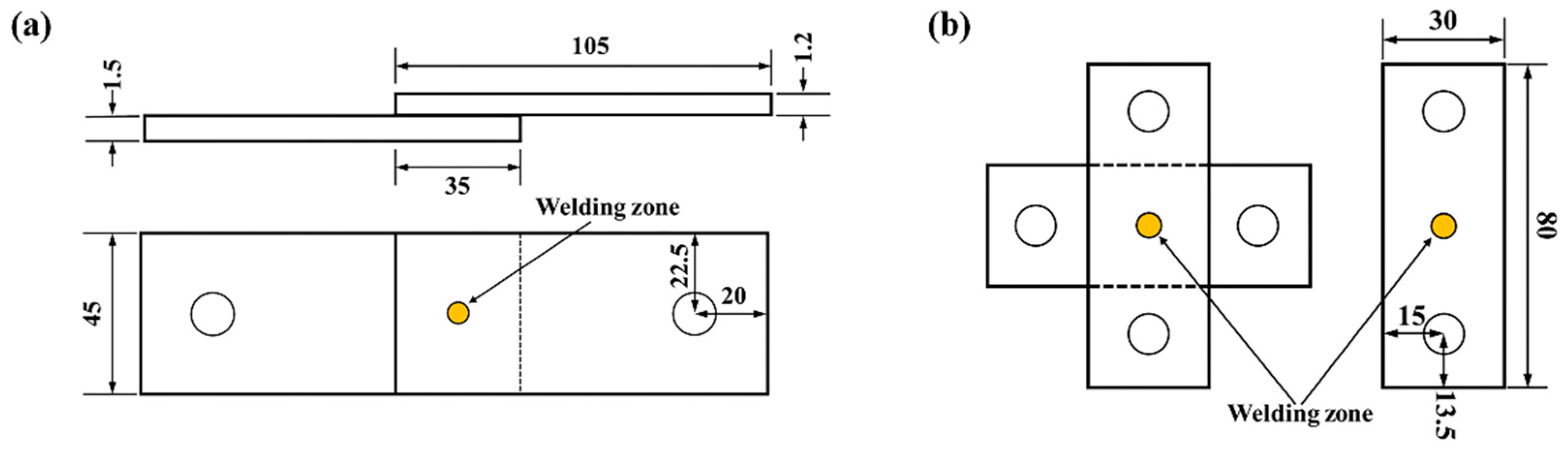
3. Experimental Materials and Procedure

The materials are 22MnB5 boron steel with thicknesses of 1.5 and 1.2 mm. The chemical composition is shown in Table 1. The composition of this type of boron steel is characterized by the addition of a certain amount of boron elements to the steel, due to boron segregation in the austenite grain boundaries delaying the formation of ferrite and bainite nuclei; hence, the strength of the steel increased. The steel has a yield strength of approximately 400 MPa, ultimate tensile strength (UTS) of around 600 MPa, and approximately 22% total elongation. After hot stamping, the material’s yield strength exceeds 1000 MPa and UTS reaches 1500 MPa. The total elongation of the final part is typically over 5% [11].
A 220 KW intermediate frequency DC RSW machine was used to weld high temperature tensile shear and cross-tension specimens, respectively. The dimensions of the welded specimens are shown in Figure 2. The main welding parameters are as follows: electrode pressure of 3.5 KN, welding current of 7 KA, welding time of 20 cyc, and nugget diameter of 6 mm.
To study the effect of the hot stamping process on the microstructures and mechanical properties of welded joints, the welded joint specimens were heated in a resistance furnace to 930 °C for 5 min, then air-cooled to 750 °C and water-cooled to room temperature to obtain heat-treated welding spots (HT welding spots). A welding spot that has not been heat-treated after spot welding is called an original welding spot (O welding spot). The two kinds of welding spots were cut along the center of the fusion center, and the profiles were sandpapered and polished with φ0.25 μm diamond powder, and then etched with 4% nitric acid alcohol solution for 15–20 s. The CMY40 (Shanghai Optical Instrument Factory, Shanghai, China) metallographic microscope was used to observe the microstructures of the O welding spot and the HT welding spot. A DHV-1000Z (Shanghai Shangcai Instrument Co., Ltd., Shanghai, China) digital display microhardness testing machine was used to measure the hardness distribution of the O and HT welded spots along the horizontal direction. The load was 200 g and holding time was 15 s. Each hardness test experiment was repeated three times and then averaged.
The welding spot specimens were heated to 930 °C for 5 min using a resistance furnace and then transferred to a high temperature tensile test machine after air-cooling to the forming temperatures (650, 700, 750, 800 and 850 °C) for tensile shear and cross-tension experiments. The load–displacement curves were recorded. The loading speed was set to be constant as 2 mm/min. The experiments were repeated twice under each condition.

4. Results and Discussion

4.1. Microstructures

Figure 3 shows the microstructures of the O welding spot. In Figure 3a, it is clearly observed that the O welding spot is composed of three parts: the base material, the representative intermediate critical heat-affected zone, and the fusion zone. The base material is mainly pearlite and ferrite, as shown in Figure 3b. In the intermediate critical heat-affected zone (Figure 3c), it is mainly ferrite, pearlite and martensite. In the fusion zone, it is mainly martensite, as shown in Figure 3d. The microstructure of the HT welding spot is shown in Figure 4. It can be found that the microstructures of the base material and the intermediate critical heat-affected zone are not significantly different from each other and are mainly uniform with finer martensite, as shown in Figure 4b–d. The reason for this is that after the welding spot was austenitized and quenched by cold water, and the original ferrite and pearlite were transformed to martensite after rapid quenching.

4.2. Hardness Profiles of Welding Spots

Figure 5 shows the hardness profiles of the welding spots. The hardness of the O welding spot is about 500 HV in the fusion zone and about 190 HV in the base material. The hardness drops sharply in the heat-affected zone and an evident softening zone appears. This is due to the extremely fast heating and cooling rate in the process of resistance spot welding, resulting in a large difference in temperature between the fusion zone and the heat-affected zone. Ghassemi-Armaki’s study [20] demonstrated that the heat-affected zone is a vulnerable region of the welding spot and is prone to weld failure. For the HT welding spot, the hardness values of the base material, the heat-affected zone and the fusion zone all reach about 500 HV. The hardness profile exhibits an approximately horizontal straight line, and the heat-affected softening zone that existed in the O welding spot disappears. This is because the welded spot first obtained the high temperature uniform austenite in the heat treatment process, and the base material, heat-affected zone and fusion zone were transformed into martensite after water-cooled quenching. Therefore, the hardness distribution is not significantly different.

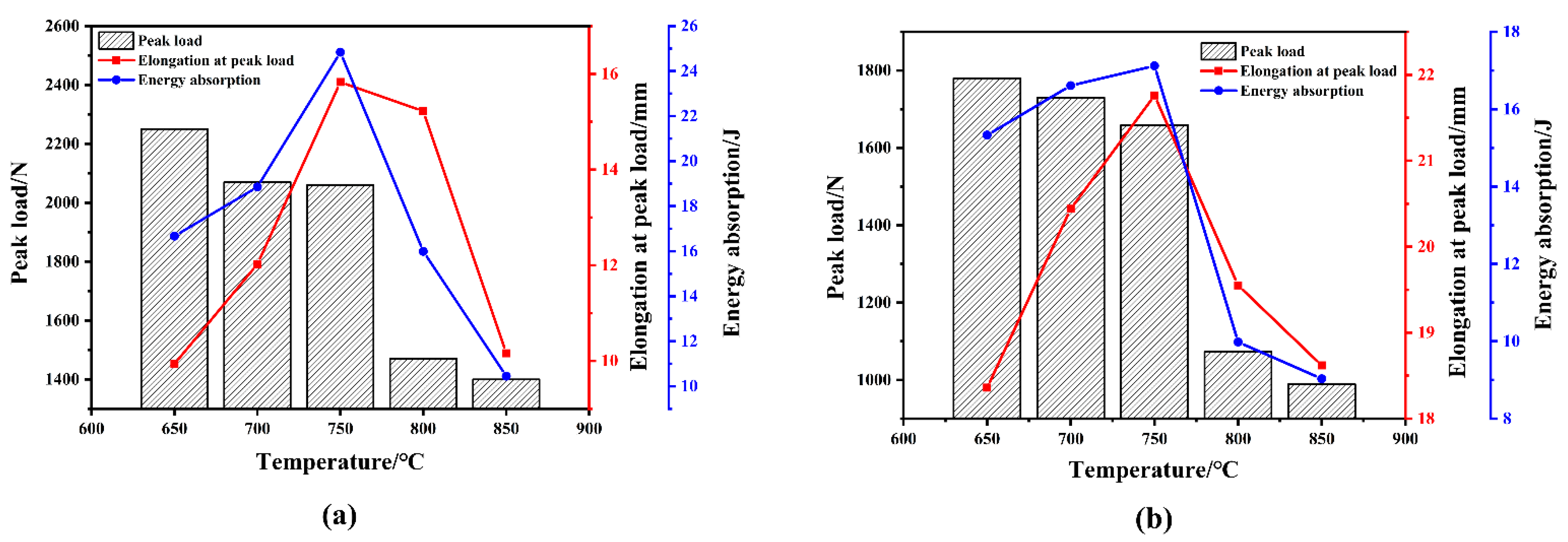
4.3. High Temperature Tensile Shear and Cross-Tensile Strength

The stresses on the welding spot under tensile shear and cross-tension conditions are shown in Figure 6 [21]. In the tensile shear test, the welding spot was subjected to shear stresses only, while the base material was subjected to shear stresses and tensile stresses in the thickness direction. In the cross-tension test, the welding spot and the base material were subjected to tensile stresses. Figure 7 shows the typical load–displacement curves of welding spots under tensile shear and cross-tension conditions [21]. Pmax is the peak load and Lmax is the displacement under peak load and is used to evaluate the elongation of the welding spot. Wmax is the energy absorption work, which is used to evaluate the energy absorption of the welding spot. A higher Wmax value indicates the improved impact resistance of the welding spot.
Figure 8 shows the results of the tensile shear experiments on the welding spots at different temperatures. It can be seen that the load increases linearly with displacement in the initial stage, and shows a nonlinear relationship before the peak load, which is remarkably similar to the load–displacement curve for the tension of plastic metals due to the strain hardening of the base material. As the load continues to increase and reaches the peak load, cracks begin to develop and the load then decreases, producing a pull-out failure when the crack is fully extended along the perimeter of the fusion core. After reaching the peak load, the load decreases relatively slowly, and as the displacement increases, the curve takes on a “long tail” shape. It is caused by the fact that after the welding spot was pulled out, the base material would be affected by the shear and thickness direction stretching, resulting in a tear along the loading direction, and when the tear was in contact with the outer end of the base material loading direction, the welding spot would be completely fractured.
Figure 9 shows the results of high temperature cross-tension experiments on welding spots. In the high temperature cross tension test, the load–displacement curve remained approximately linear until the peak load was reached, after which the curve decreased rapidly, showing a “short tail” shape. This is due to the fact that the failure mode of the welding spot during the high temperature cross-tension process is the “pulled out” mode, and in a short time, the welding spot is separated from the base material and the specimen is fractured.
Figure 10 shows the peak load, elongation at peak load, absorption capabilities for high temperature tension shear and high temperature cross tension at different temperatures. As can be seen from Figure 10a, the peak load in the high temperature tension shear experiment decreases with the increase in temperature. It reached a maximum value of 2.3 KN at 650 °C. The peak load decreases at 700 and 750 °C, but the decrease is relatively small. The peak load decreases significantly with temperatures of above 800 and at 850 °C; it reaches only about half of the value at 650 °C. The elongation and energy-absorbing activities under the peak load increase with the increased temperature, reaching a peak at 750 °C, and then shows a decreasing trend. This is because the plasticity of the material increased and the strength of the welding spot began to decline as the temperature was increased. In the high temperature cross-tension test, the peak load showed similarity with the tensile shear test, i.e., a decreasing trend with the increase in the deformation temperature. However, the peak load at each temperature is lower than that in the tension shear test, which is about two-thirds of that in the tension shear test, as shown in Figure 10b. In the high temperature cross-tension test, the elongation and energy absorption activities at peak load first increase with the increase in temperature, reach a peak at 750 °C, and then show a decreasing trend. For the hot stamping of UHSSP, the welding spot has good comprehensive properties of strength and ductility at 750 °C. When the forming temperature is greater than 750 °C, although the rheological stress of the material is relatively low, the low strength of the welding spot at this time may lead to the failure of the welding spot in the area of larger deformation during the forming process. When the forming temperature is lower than 750 °C, the strength of the welding spot is higher, but the material formability is reduced. Consequently, 750 °C is the suitable forming temperature for the hot stamping of UHSSP.

5. Conclusions

In this paper, the mechanical properties of 22MnB5 steel patchwork blank welding spots at high temperature and the effect of a heat treatment process on microstructures and properties of welding spots were studied through microstructure observations, hardness tests and high temperature tension shear and cross-tension experiments. The following conclusions were obtained:
(1)
Compared with the original welding spot, there was no heat-affected softening zone in the heat-treated welding spot, and the base material and fusion zone were fine uniform martensite. For the heat-treated welding spot, the hardness values of the base material, the heat-affected zone and the fusion zone all reached about 500 HV, and the hardness profile was an approximately horizontal distribution.
(2)
In the high temperature tension shear and cross-tension experiments, the peak load of the welding spot decreased with the increase in forming temperature, and the decline was relatively slight at 750 °C and the displacement and energy absorption activities under peak load were larger. Therefore, it was more appropriate for patchwork blanks to be formed at about 750 °C.

Author Contributions

X.O. helped perform the analysis with constructive discussions and wrote the manuscript; Z.Z. contributed to the conception of the study; H.J. performed the data analyses; M.R. performed the experiment; Y.S. provided experimental materials and process validation. All authors have read and agreed to the published version of the manuscript.

Funding

This research was funded by National Natural Science Foundation of China (51205162).

Acknowledgments

We would like to thank the anonymous reviewers for their helpful remarks.

Conflicts of Interest

The authors declare no conflict of interest.

References

  1. Tisza, M.; Czinege, I. Comparative study of the application of steels and aluminium in lightweight production of automotive parts. Int. J. Lightweight Mater. Manuf. 2018, 1, 229–238. [Google Scholar] [CrossRef]
  2. Caldwell, B.W.; Namouz, E.Z.; Richardson, J.L. Automotive light-weight engineering: A method for identifying lazy parts. Int. J. Veh. Des. 2013, 63, 364–368. [Google Scholar] [CrossRef]
  3. Hong, L.; Xin, L. The Present Situation and the development trend of new materials used in automobile lightweight. Appl. Mech. Mater. 2012, 1918, 58–62. [Google Scholar] [CrossRef]
  4. Rong, C.G.; Na, W.; Gui, R.Z. New materials for auto-body lightweight applications. Adv. Mater. Res. 2012, 1460, 226–230. [Google Scholar] [CrossRef]
  5. Yan, L.; Hai, Q.Y.; Yu, Y. Research on microstructure and properties of automobile body steel and its development trend. IOP Conf. Ser. Mater. Sci. Eng. 2018, 382. [Google Scholar] [CrossRef] [Green Version]
  6. Chang, Y.; Meng, Z.H.; Ying, L. Influence of hot press forming techniques on properties of vehicle high strength steels. J. Iron Steel Res. Int. 2011, 18, 59–63. [Google Scholar] [CrossRef]
  7. Hikida, K.; Nishibata, T.; Kikuchi, H. Static strength of hot-stamped spot welded joints: Study on spot welding tailored blank technology. Weld. Int. 2013, 31, 681–691. [Google Scholar] [CrossRef]
  8. Nader, M.; Ketabchi, M.; Abbasi, M. Analysis of micro-structure and mechanical properties of different high strength carbon steels after hot stamping. J. Mater. Process. Technol. 2011, 211, 1117–1125. [Google Scholar] [CrossRef]
  9. Turetta, A.; Bruschi, S.; Ghiotti, A. Investigation of 22MnB5 formability in hot stamping operations. J. Mater. Process. Technol. 2006, 177, 396–400. [Google Scholar] [CrossRef]
  10. Alexander, B.; Christopher, P.S.; Sooky, W.; Mary, A.W.; Michael, J.W. Effect of cooling rate on the high strain rate properties of boron steel. Int. J. Impact. Eng. 2010, 37, 694–702. [Google Scholar] [CrossRef]
  11. Karbasian, H.; Tekkaya, A.E. A review on hot stamping. J. Mater. Process. Technol. 2010, 210, 2103–2118. [Google Scholar] [CrossRef]
  12. Wang, Z.; Liu, P.; Xu, Y. Hot stamping of high strength steel with tailored properties by two methods. Procedia Eng. 2014, 81, 1725–1730. [Google Scholar] [CrossRef] [Green Version]
  13. Merklein, M.; Wieland, M.; Lechner, M.; Bruschi, S.; Ghiotti, A. Hot stamping of boron steel sheets with tailored properties: A review. J. Mater. Process. Technol. 2016, 228, 11–24. [Google Scholar] [CrossRef]
  14. Feng, Y.; Mingtu, M. Study on the Resistance Spot Welding Technology of 22MnMoB Hot Stamping Quenched Steel. Engineering 2014, 12, 45–53. [Google Scholar] [CrossRef]
  15. Bai, S.J.; Wang, C. Mechanical properties and microstructure of resistance spot welded joint of hot stamping 22MnB5 boron steel. J. Beijing Univ. Technol. 2013, 39, 666–670. [Google Scholar]
  16. Yang, L.; Zhen, L. Microstructure and tensile-shear pro-perties of resistance spot welded 22MnMoB hot-stamping annealed steel. J. Mater. Eng. Perform. 2017, 26, 424–430. [Google Scholar] [CrossRef]
  17. Lu, Y.; Andrea, P.; Tim, A.; Menachem, K.; Zhang, W. Subcritical heat affected zone softening in hot-stamped boron steel during resistance spot welding. Mater. Des. 2018, 155, 170–184. [Google Scholar] [CrossRef]
  18. Mohamadizadeh, A.; Biro, E.; Worswick, M. spot weld strength modeling and processing maps for hot-stamping steels. Weld. Res. 2019, 98, 241–249. [Google Scholar] [CrossRef]
  19. Naderi, M.; Durrenberger, L.; Molinari, A.; Bleck, W. Constitutive relationships for 22MnB5 boron steel deformed isothermally at high temperatures. Mat. Sci. Eng. A 2008, 478, 130–139. [Google Scholar] [CrossRef]
  20. Ghassemi, A.H.; Bhat, S.; Kelley, S. Quasistatic spot weld strength of advanced highstrength sheet steels. Weld. Res. 2017, 96, 104–112. [Google Scholar]
  21. Pouranvari, M.; Marashi, S.P.H. Critical review of automotive steels spot welding: Process, structure and properties. Sci. Technol. Weld. Join. 2013, 18, 361–403. [Google Scholar] [CrossRef]
Figure 1. Process flow chart of the hot stamped ultra-high strength steel patchwork blanks (UHSSP).
Metals 11 01033 g001
Figure 2. Geometries of the specimens: (a) tensile shear specimen; (b) cross-tensile specimen.
Metals 11 01033 g002
Figure 3. Microstructures of the O welding spot: (a) overview of the welded joint; (b) base metal; (c) intermediate critical heat-affected zone; (d) fusion zone.
Metals 11 01033 g003
Figure 4. Microstructures of the HT welding spot: (a) overview of the welded joint; (b) base metal; (c) intermediate critical heat-affected zone; (d) fusion zone.
Metals 11 01033 g004
Figure 5. Hardness profiles of the O welding spot and the HT welding spot.
Metals 11 01033 g005
Figure 6. Stress distribution at the interface of two blanks and circumference of a weld nugget: (a) tensile shear test; (b) cross-tension tests.
Metals 11 01033 g006
Figure 7. Typical load–displacement curves for the tensile shear and cross-tensile tests.
Metals 11 01033 g007
Figure 8. Load–displacement curves of high temperature tensile shear tests.
Metals 11 01033 g008
Figure 9. Load–displacement curves of high temperature cross-tension tests.
Metals 11 01033 g009
Figure 10. Effect of temperature on peak load, elongation at peak load, and energy absorption: (a) tensile shear test; (b) cross-tension test.
Metals 11 01033 g010
Table 1. Chemical composition of 22MnB5 steel (wt %) [19].
CSiMnPSCrTiBFe
≤0.250.231.2≤0.02≤0.01≤0.20≤0.300.003Bal.
Publisher’s Note: MDPI stays neutral with regard to jurisdictional claims in published maps and institutional affiliations.

