Article

Effect of Double-Pulse Characteristics on Weld Bead Formation and Mechanical Properties in Metal Inert Gas Welding

1
College of Mechanical and Electrical Engineering, Guangzhou Institute of Technology, Guangzhou 510075, China
2
School of Mechanical and Automotive Engineering, South China University of Technology, Guangzhou 510640, China
*
Author to whom correspondence should be addressed.
Metals 2021, 11(6), 995; https://doi.org/10.3390/met11060995
Submission received: 29 May 2021 / Revised: 16 June 2021 / Accepted: 17 June 2021 / Published: 21 June 2021

Abstract

:
Aluminum alloy has been widely used due to its excellent workability, and double-pulse metal inert gas welding (MIG) has become a popular technique in aluminum alloy welding. In this study, a cross-complementary test was performed to study the effect of double-pulse characteristics on weld bead formation and mechanical properties in MIG welding. The test was carried out on an AA6061 aluminum alloy using flat overlaying welding. After welding, the micro-metallographic structure and macro-mechanical performance of the weld bead were explored. The test results showed that the two methods of increasing the base current amplitude or the low-frequency of the current effectively enhanced the oscillation of the molten pool, refined the grain size of the fusion zone, and improved the mechanical properties of the weld. Additionally, by comparing the macroscopic photograph of the specimen and the corresponding welding parameters in the test, the formation characteristics of the bead’s fish-scale pattern in double-pulse MIG welding were found when appropriate welding parameters were adopted and weld bead formation was good. This test result provides a strong scientific basis for the selection of welding parameters in the actual promotion and application of double-pulse MIG welding.

1. Introduction

As a type of light alloy whose annual global output is second only to steel, aluminum alloys have quickly attracted attention in the fields of aerospace, automobiles, ships, bridges, machinery manufacturing, and others, and has been widely used since it emerged in the aviation industry due to its excellent workability, corrosion resistance, impact resistance, and other properties [1,2]. However, the low melting point, high thermal conductivity, and large linear expansion coefficient of aluminum alloys can result in defects such as deformation, pores, and thermal cracking during welding [3,4]. In addition, the melting point of the protective oxide film on the surface of the aluminum alloy is high and makes it challenging to generate a welding arc.
Double-pulse MIG welding has become a popular research topic in aluminum alloy welding due to its simple process, wide current adjustment range, low porosity, and small grains in the fusion zone. Mathivanan et al. showed that the periodic alternation between strong and weak groups of double pulses could enhance the oscillation of the molten pool and refine the crystal grains [5,6]. Jin Li found that changing the difference between the base current of the strong and weak pulse groups was the ideal mode for double-pulse MIG welding [7]. Liu Anhua et al. showed that the arc force in the strong and weak pulse area and the change in the transition frequency of the droplet during double-pulse welding caused oscillation in the molten pool [8,9,10]. Yuan found that the oscillation of the molten pool was the cause of grain refinement in magnesium alloy welding [11]. Takai et al. reported that grain refinement could effectively reduce solidification cracks [12,13,14]. As above-mentioned, the existing related research results have mostly focused on the theoretical inference and modeling of molten pool oscillations, but the actual microscopic effects of oscillations are rarely reported. On the welding method, Li Hongliang used an ultrasonic arc to increase the oscillation of the molten pool in MIG welding [15]. Shao Yingkai used plasma-MIG hybrid welding to reduce the welding crack sensitivity [16]. Zhang Tiehao superimposed MIG and FSW welding to improve the mechanical properties of the weld [17]. In comparison to changing the characteristic parameters of the current in double-pulse MIG welding, the process of those welding is too complicated. Therefore, the starting point of this study was the actual microscopic influence of the molten pool oscillation under double-pulse characteristics, and the changes in the mechanical properties of the weld under this influence. We attempted to find a realistic basis for the microscopic and macroscopic effects of the molten pool oscillation on double-pulse MIG welding, and then provide a strong scientific basis to promote the practical application of MIG welding.
Therefore, under the premise that the average current of welding is constant, a cross-complementary method was used to achieve two comparative test results, that is, the impact of the base current amplitude of the strong and weak pulse groups and the low-frequency of current on the formation and performance of weld bead in MIG welding. After obtaining a good welding effect, the following processes were undertaken:
(i)
We examined the relationship between the formation of fish-scale pattern and double-pulse current characteristics;
(ii)
Through the observation of the metallographic structure, we determined the microscopic “evidence” of the oscillation in the molten pool;
(iii)
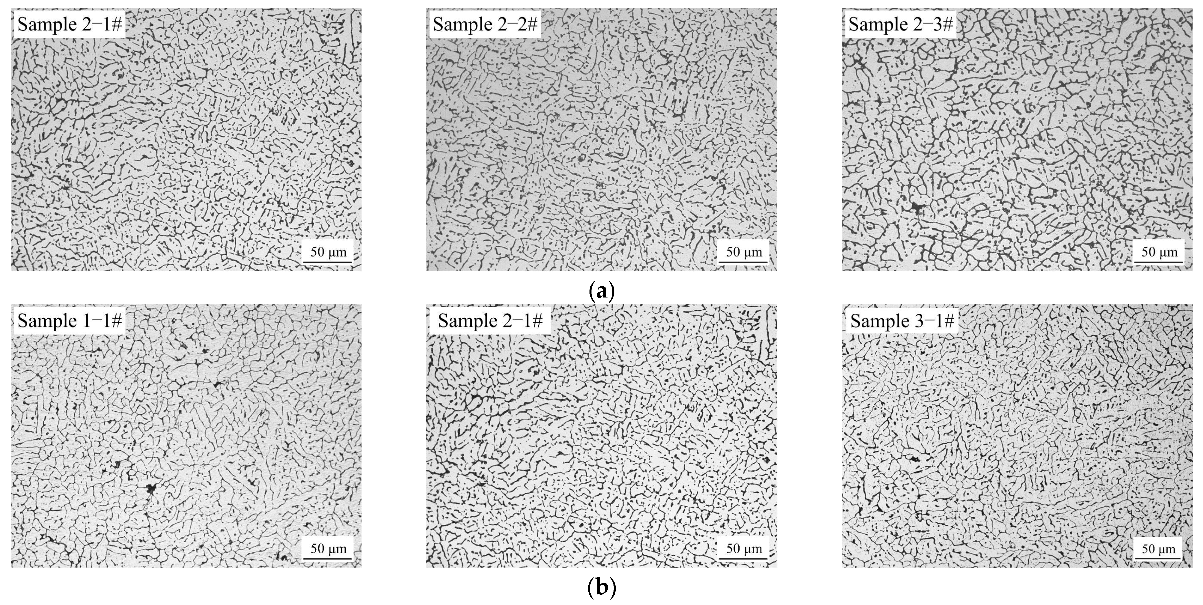
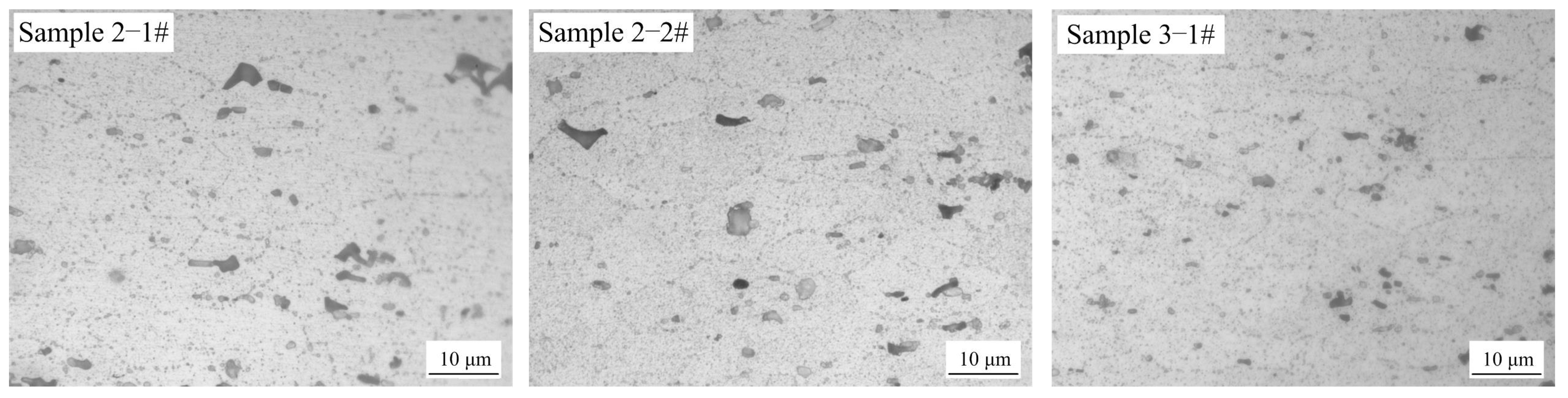
Through the observation of the metallographic structure, the influence of the molten pool oscillation on the grain size was explored from the microscopic point of view; and
(iv)
By conducting a tensile test, hardness test, and electron microscope scanning of the fracture of the sample, the effect of the molten pool oscillation on the mechanical properties of the weld was explored from the macroscopic perspective.

2. Materials and Methods

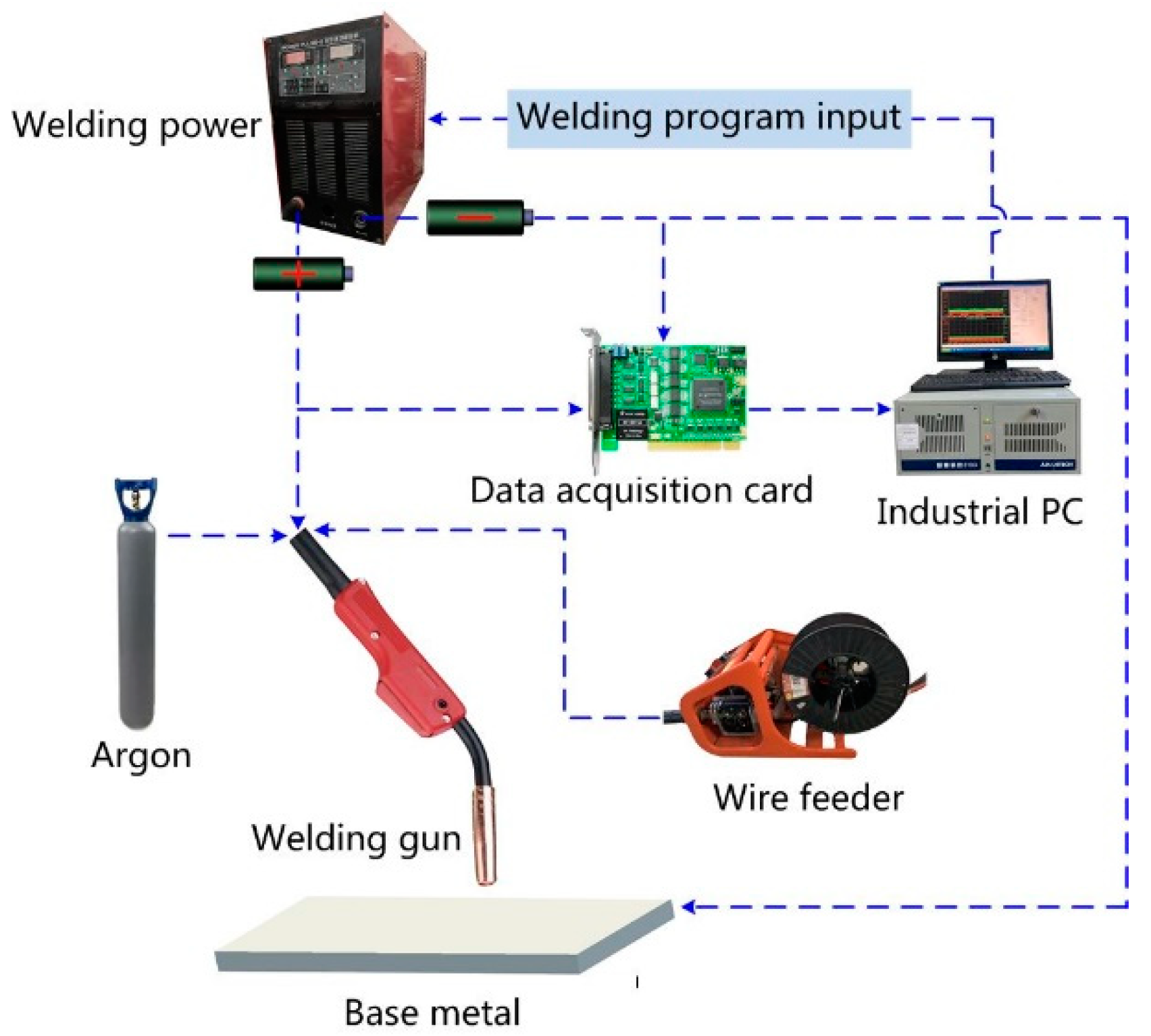
2.1. Test Materials and Equipment

The flat overlaying welding method was adopted and the welding was performed with a Power Pulse Ⅱ 350 digital welding machine developed independently by the research group (Guangzhou, China). The base metal used was an AA6061 aluminum alloy that is widely used in many important industrial fields such as aviation, aerospace, subway vehicles, railway passenger cars, etc. [15,18]. It exhibits excellent workability, welding performance, and corrosion resistance as well as good mechanical properties, its maximum tensile strength is approximately 310 MPa, and the hardness is approximately 94 HV. The dimensions of the sample used in this study were 200 mm × 100 mm × 3 mm. The welding wire used for welding was ER4043 with a diameter of 1.2 mm. ER4043 is a universal aluminum alloy welding wire with excellent thermal crack resistance. It is suitable for the welding of AA6061 aluminum alloy and can ensure good mechanical properties. The compositions of the base metal AA6061 and welding wire ER4043 are presented in Table 1 (provided by the manufacturer). A schematic of the welding system is illustrated in Figure 1. The current and voltage signals in the welding process were collected in real time using a wavelet analyzer (developed by the research group, Guangzhou, China) built on an industrial PC.

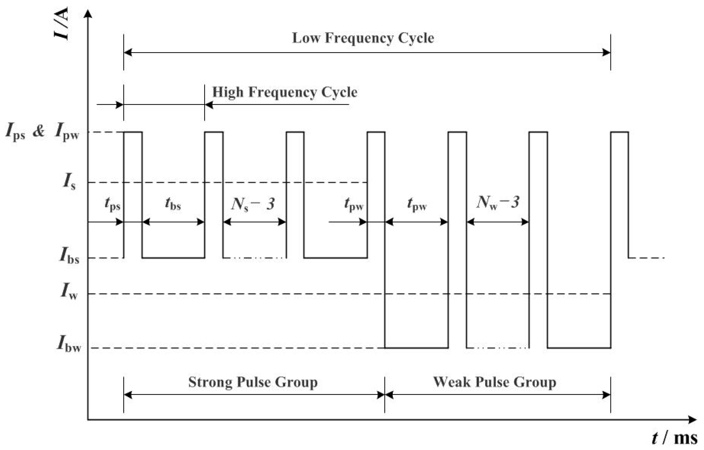
2.2. Test Conditions

Figure 2 shows the schematic of the current waveform of the double-pulse MIG welding used in the test, where Ips and tps are the peak current of the strong pulse and its duration, respectively, and Ibs and tbs are the base current of the strong pulse and its duration, respectively. Similarly, Ipw and tpw are the peak current of the weak pulse and its duration, and Ibw and tbw are the base current of the weak pulse and its duration, respectively. In addition, Ns and Nw are the number of pulses of the strong and weak pulse groups in a low-frequency cycle, respectively; Is and Iw are the average currents of the strong and weak pulse groups, respectively; Iavg is the average current of welding; and flow is the low-frequency of current in double-pulse welding.
To prevent the occurrence of welding defects such as collapse, deformation, and cracks, the control of the heat input needs to be precise in the test not only because of the low melting point and high thermal conductivity of the AA6061 aluminum alloy, but also because the thickness of the base metal was only 3 mm. In fact, the heat input is determined by the interaction between the welding current, voltage, and welding speed. Therefore, after a large number of tests based on the database of welding experts established by the research group [7], appropriate welding parameters were obtained.
The welding voltage used in the test was 22 V with a welding speed of v1 = 7.8 mm/s and wire feeding speed of v2 = 10 mm/s. The dry extension of the welding wire was 10 mm, the gas flow rate was 17 L/min, and argon was used as the shielding gas with a concentration of 99.99%. The values of the remaining test parameters are presented in Table 2.
To study the effect of the low-frequency of current on the microstructure and macro characteristics of the weld, three sets of tests were performed with a low-frequency of 2, 5, and 8 Hz, which were within a reasonable range [7]. Under each low-frequency, three sets of tests were selected with different base current amplitudes to study the effect of base current amplitude on the microstructure and macro characteristics of the weld.
Within a specific period, the average current can be expressed as [19]
I = 0 T i ( t ) d t T
where I is the average current of the power supply output during a specific period and T is the specific time period. As illustrated in Figure 2 and according to Equation (1), we can determine the mathematical relationship between the related parameters, as summarized in Table 2.
I s = ( I ps t ps + I bs t bs ) × N s T
I w = ( I p w t pw + I bw t bw ) × N w T
I avg = ( I ps t ps + I bs t bs ) × N s + ( I pw t pw + I bw t bw ) × N w T
f low = 1 ( t ps + t bs ) × N s + ( t pw + t bw ) × N w
After the welding, the metallographic specimens were polished using 800, 1200, 3000, and 5000 sandpaper and were then rough polished with W2.5 and fine polished with W1 abrasive paste until the surfaces were bright and free of scratches. Subsequently, Keller reagent was used to corrode the surfaces for approximately 1 min.

3. Test Results and Analysis

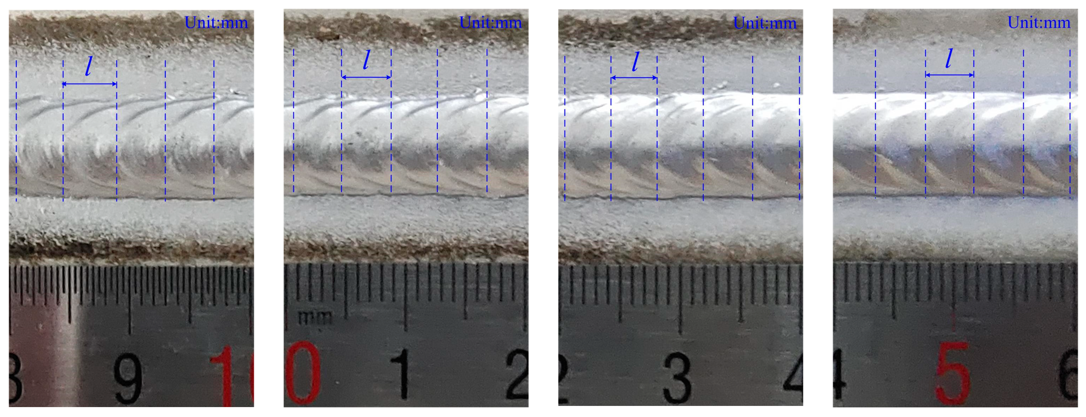
3.1. Weld Bead Appearance Analysis

Figure 3 shows photographs of the weld bead obtained from the test. It can be observed that the welding parameter test settings achieved stable welding. All welds had the same melting width (approximately 8 ± 0.1 mm), uniform clear width, and no welding collapse, undercutting, welding cracks, or other unfavorable phenomena, and there was almost no spatter in the samples except for sample 2-3#.
Synthesizing the values of the test parameters in Table 2, it can be observed that the greater the base current amplitude of the strong and weak pulse groups, the easier it is to obtain clear and beautiful fish-scale patterns (along the vertical line in Figure 3). Similarly, we found that the higher the low-frequency of the current, the shorter the length of the fish-scale pattern (along the horizontal line in Figure 3). The length of the fish-scale pattern is denoted as “l” in Figure 5. In actual measurements, the long-range calculation should be selected to avoid the occurrence of large errors in the measurement of a single fish-scale pattern.
According to the value of test parameters in Table 2, the low-frequency of current flow and welding speed v1 for sample 1-1# were 2 Hz and 7.8 mm/s, respectively. Accordingly, the length of the weld bead that can be formed is v1 × 1/flow = 3.9 mm in one low-frequency cycle; therefore, five low-frequency cycles were needed for a 20-mm-long weld bead. Figure 4 shows the macroscopic photograph of the 20-mm-long specimen 1-1# magnified seven times, and the specimen was parallel to the direction of the weld. The figure clearly shows that the bottom of the molten pool was periodically repeated in five sets of peaks and valleys, which were evenly spaced. This implies that each group of peak and valley corresponds to one low-frequency cycle. In double-pulse welding, the strong pulse group had a large average current, heat input, and penetration depth, whereas these were smaller for the weak pulse group. Therefore, the positions of the wave’s peak and valley correspond to the strong and weak pulse groups, respectively.
Figure 5 shows the topography of the weld bead with a length of 20 mm captured from different positions of sample 1-1#. As shown, all four pictures contained approximately five fish-scale patterns, that is, the 20-mm-long weld bead contained five sets of fish-scale patterns. Synthesizing the conclusion of Figure 4, we can draw a conclusion that in double-pulse welding, a low-frequency cycle corresponds to a fish-scale pattern and the length of the fish-scale pattern “l” represents the length of the weld bead formed in one low-frequency cycle. In other words, there exists a mathematical relationship between the fish-scale pattern “l”, low-frequency “flow”, and welding speed “v1”:
l = 1 f low × v 1
Similarly, Equation (6) is also applicable to samples 2-1# and 3-1# and it revealed the cause of the double-pulse current characteristic parameters on the appearance of the fish-scale pattern whereas the existing research results are rarely reported. This conclusion provides a strong scientific basis for those welding occasions where the weld bead is exposed and the beautiful appearance is required.

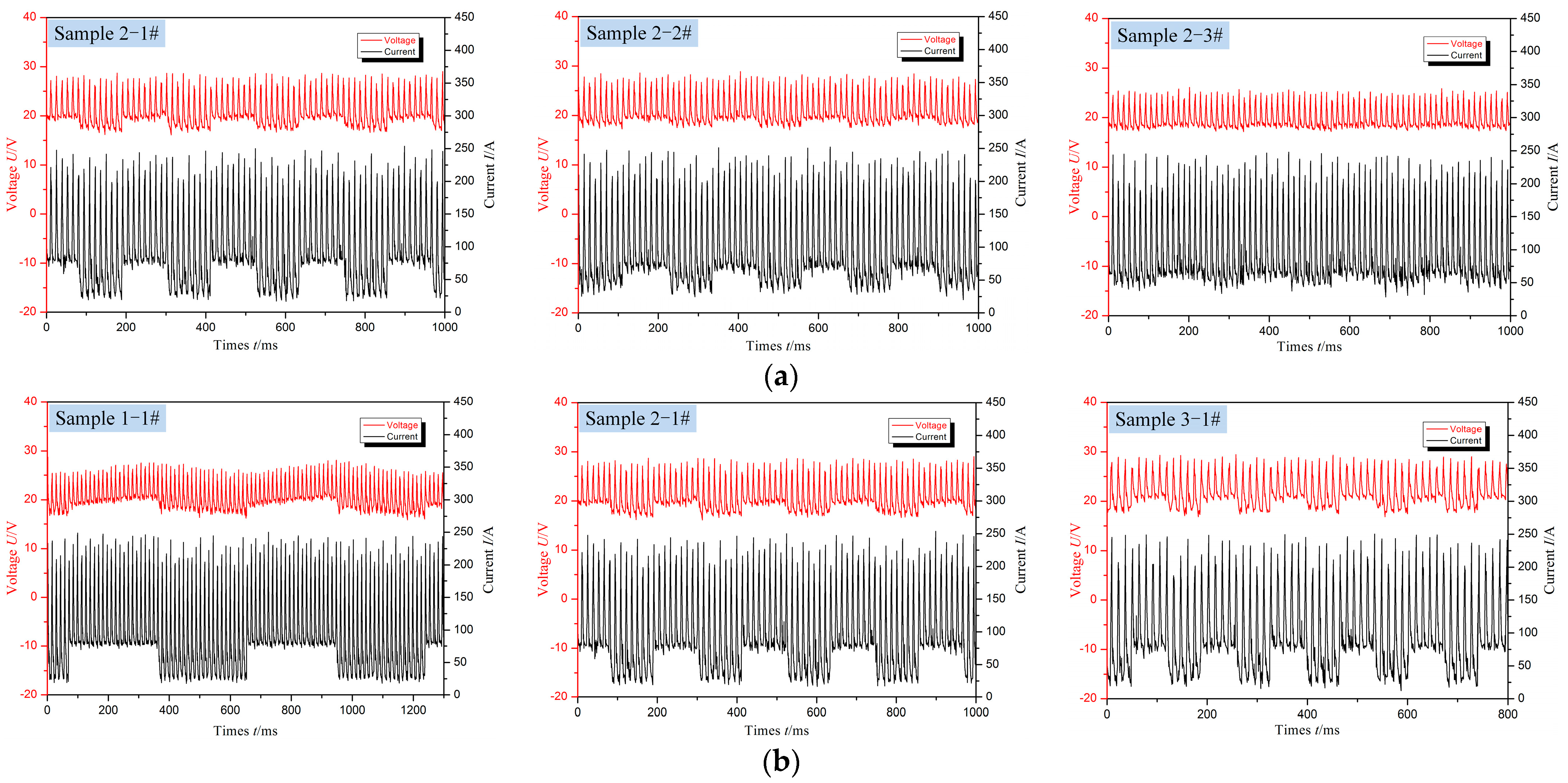
3.2. Molten Pool Oscillation Analysis

Figure 6 shows the metallographic structure of specimen 1-1# parallel to the direction of the weld. The three pictures were taken from the same position, and the magnification was sequentially enlarged two-fold. An obvious inter-crystalline “burr-like” boundary can be seen in the figure. Synthesized with the conclusion from Figure 4, we found that the boundary was at the “handover” position of two adjacent low-frequency cycles [20].
According to the value of the test parameters in Table 2, the base current amplitude for sample 1-1# was up to 50 A; therefore, we can conclude that the molten pool was subjected to strong stirring caused by the changes in the base current of the strong and weak pulse groups. This caused the growing dendrites to break during the cooling and crystallization process, thereby forming a “burr-like” boundary.
Figure 7 shows the metallographic structure of specimens 2-1# and 3-1# parallel to the direction of the weld. We also found a boundary at the “handover” position of two adjacent low-frequency cycles, but there were no burrs.
In Figure 6 and Figure 7, the special metallographic structure caused by molten pool oscillation can be seen. The results of metallographic analysis are consistent with the theoretical inference and modeling of the existing related research results, that is, the oscillation of the molten pool does cause the growing dendrites to break, which increases the nucleation rate and refines the grains.

3.3. Micro-Metallographic Structure Analysis

Figure 8 shows the metallographic structures of specimens 1-1#, 1-2#, and 1-3# perpendicular to the direction of the weld, which were captured from the middle of the molten pool in the strong pulse zone. Extremely coarse grains were observed in this zone. The equipment used for observation of the metallographic structure for all specimens in this test was an electron microscope (LEICA DMI5000, Wetzlar, Germany). The actual size of the image with a scale of 50 μm was 586 μm × 440 μm. Therefore, among the three specimens shown in Figure 8, the coarse grains in specimen 1-1# were the most significant and the maximum range observed was approximately 0.40 mm × 0.30 mm. The coarse grains in this interval were due to the small difference between the peak and base currents of the strong pulse group. In comparison with the weak pulse group, the post-weld cooling temperature gradient of the strong pulse group was small, the cooling rate was slow, the degree of undercooling was small, and nucleation rate had no obvious advantage over the nucleus growth rate. Hence, coarse grains appeared but the intergranular orientation angle was relatively large, which is consistent with the actual situation in which there is no preferential orientation of heat dissipation in the middle of the molten pool.
In the two comparative tests, each set of test results with the best welding effect was selected for micro-metallographic analysis. Specimens 2-1#, 2-2#, and 2-3# with the same low-frequency of current of 5 Hz were selected to study the effect of the base current amplitude on the microstructure, as shown in Figure 10a. Specimens 1-1#, 2-1#, and 3-1# with the same base current amplitude were selected to study the effect of the low-frequency of the current on the microstructure, as shown in Figure 10b. Figure 9a,b shows the welding current and voltage waveforms corresponding to Figure 10a,b, respectively.
Figure 10a shows the metallographic structure of the fusion zone of specimens 2-1#, 2-2#, and 2-3#. As shown, with a decrease in the amplitude of the base current of the strong and weak pulse groups, the grain size tended to significantly increase. Figure 10b shows the metallographic structure of the fusion zone of specimens 1-1#, 2-1#, and 3-1#. As shown, with the increasing current low-frequency, the grain size tended to decrease. The two results indicate that increasing the base current amplitude or the low-frequency of the current can enhance the oscillation of the molten pool and refine the grains of the fusion zone. In reality, the large current of the strong pulse group produces a large arc force, and the droplet transition frequency is high, whereas the weak pulse group produced the opposite effect [21,22,23,24]. Therefore, as the amplitude of the base current increases, the periodic strong and weak changes in the arc force and the transition frequency of the molten droplet strengthen the stirring of the molten pool. As a result, a large number of dendrites are broken up during the process of crystallization. This increases the nucleation rate and effectively promotes the refinement of grains. Similarly, increasing the low-frequency of the welding current speeds up the mutual switching of strong and weak pulse groups, and this can effectively enhance the weld pool oscillation.

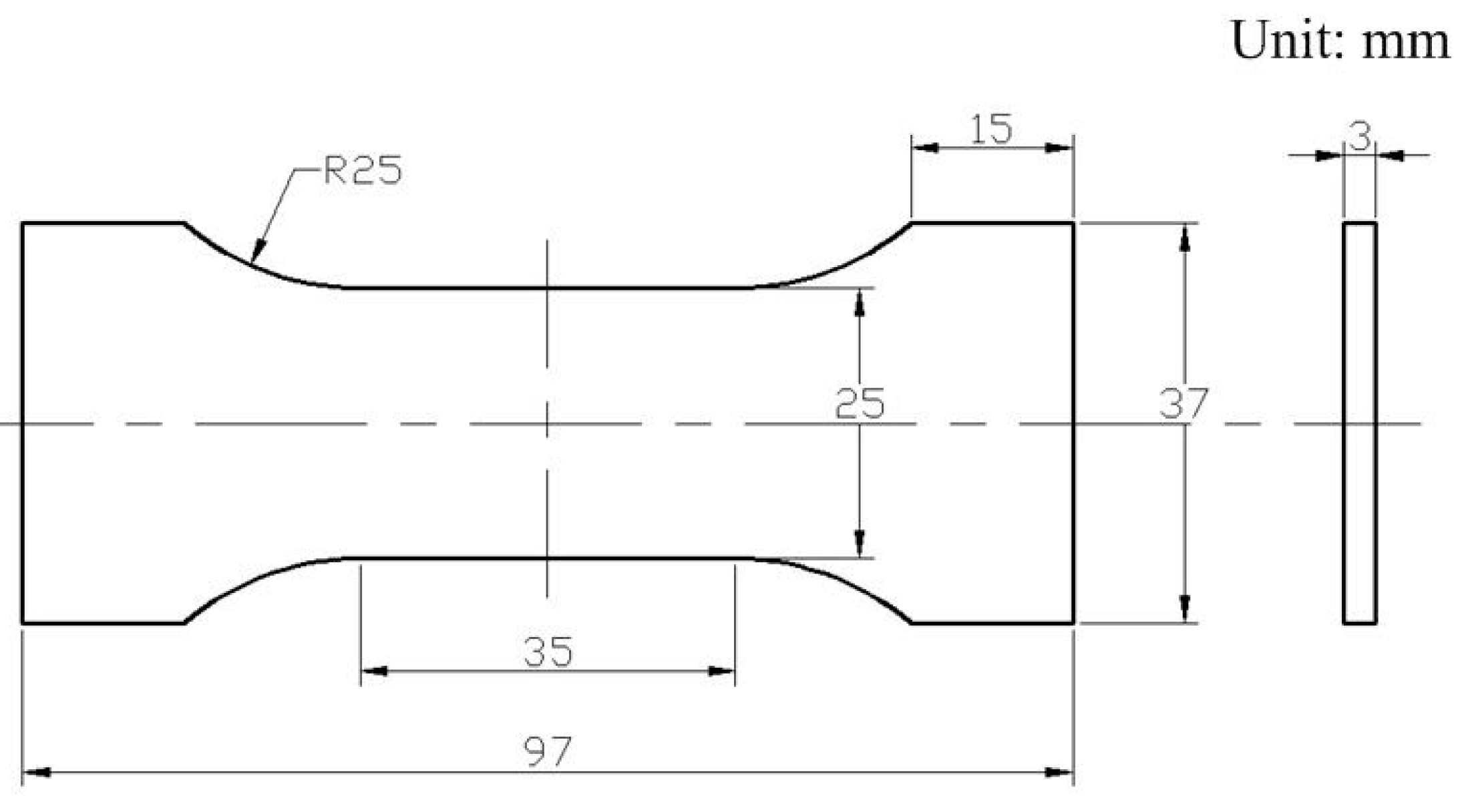
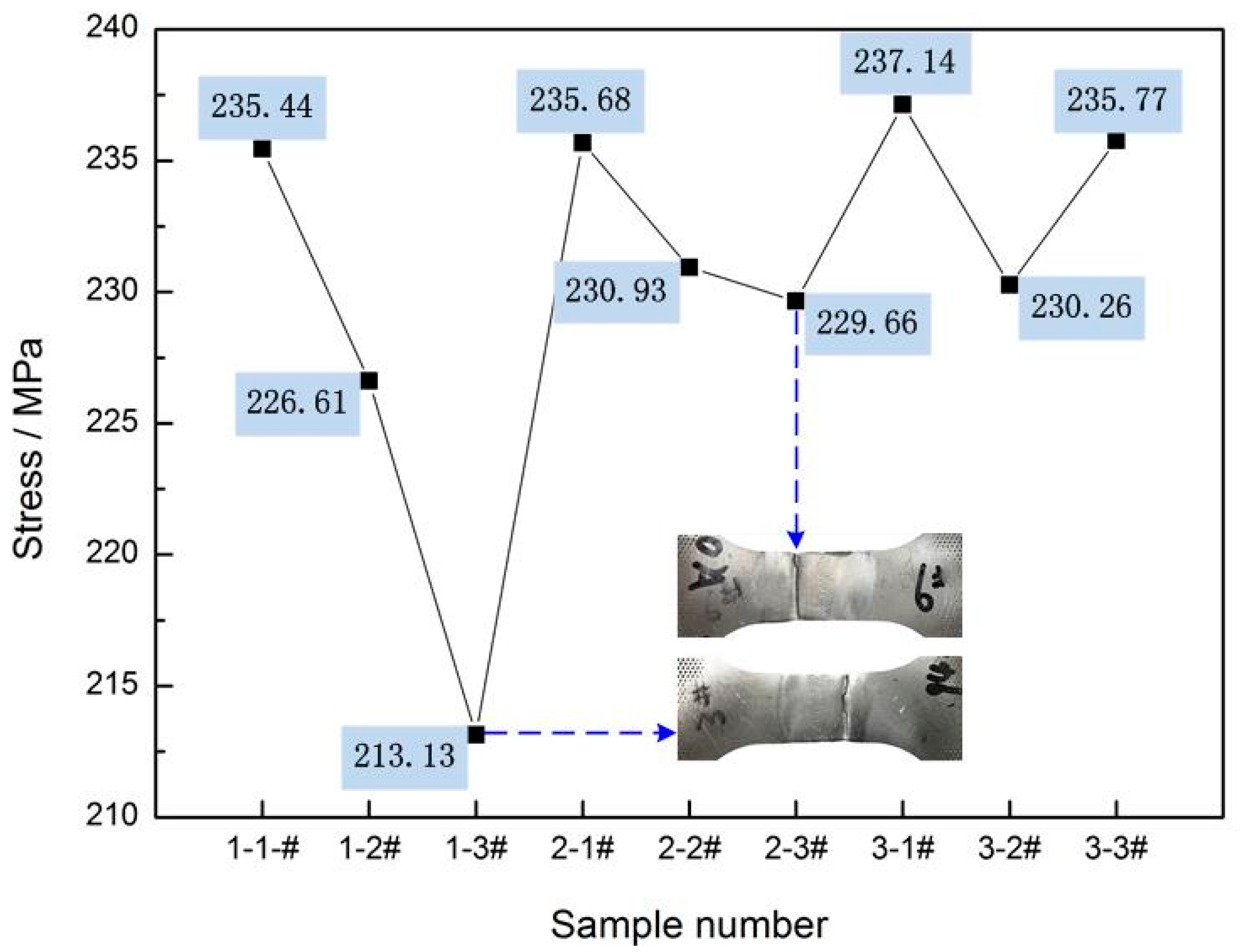
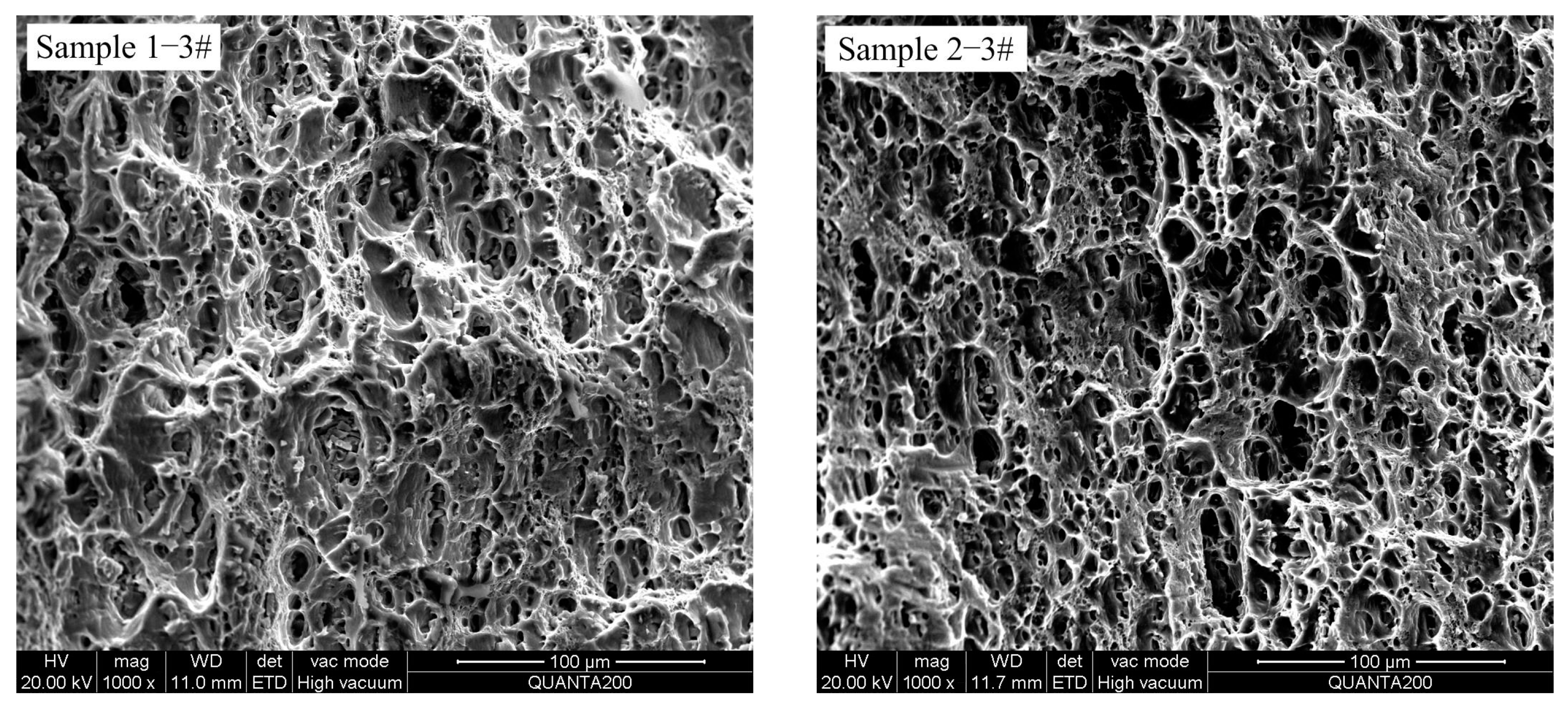
3.4. Macro-Mechanical Performance Analysis

Theoretically, fine grains can comprehensively improve the mechanical properties of metals [25,26]. For this reason, we selected specimens corresponding to Figure 10a,b for hardness testing and conducted tensile performance tests on all nine specimens. Figure 11 shows the size specification of the tensile specimens taken from the middle of the weld beads.
Figure 12 shows a comparison of the tensile test results and the fracture state of tensile specimens 1-3# and 2-3#, which had the smallest tensile strength out of all nine specimens. Based on the grain sizes in Figure 10a,b, as shown in Figure 12, the test results follow the rule that the smaller the grain size, the greater the maximum tensile strength of the samples, although all nine samples comprised welding defects such as porosity and shrinkage to a certain extent. This implies that in double-pulse MIG welding, appropriately increasing the base current amplitude of the strong and weak pulse groups or increasing the low-frequency of the current can improve the tensile strength and hardness of the weld while refining the grain.
Figure 13 shows the microhardness distributions of the specimens corresponding to Figure 10a,b. The selected load was 200 g and the indentation time was 10 s during the Vickers hardness measurement. Based on the metallographic microstructure in Figure 10a,b, the hardness of the fusion zone follows the rule that the smaller the grain size, the greater the hardness. Moreover, the hardness of the fusion zone of the specimens was significantly higher than that of the adjacent heat-affected zone, especially specimen 3-1# with the largest base current amplitude and the largest low-frequency of current, indicating that the double-pulse MIG welding used in this test achieved better welding results.
In addition, in the tensile test, the fracture positions of all nine specimens were located in the heat-affected zone 10 ± 1.5 mm away from the center of the weld, similar to the fracture positions of tensile specimens 1-3# and 2-3#, as shown in Figure 12. Figure 13 shows that the hardness of all six specimens had a stable, low hardness value at a position approximately 9 mm from the center of the weld. This indicates that the weakest position of the hardness is consistent with the weakest position of strength, and this is consistent with the positive correlation between strength and hardness.
As shown in Figure 10b, Figure 12 and Figure 13b, specimen 3-1# had the smallest grain size and the greatest tensile strength and hardness among all six specimens. Accordingly, we absolutely have reasons to believe that increasing the base current amplitude and low-frequency of current simultaneously within a reasonable range will achieve an ideal welding effect.
Figure 14 shows the metallographic structure of the three specimens, 2-1#, 2-2#, and 3-1#, 15 mm away from the center of the weld. Small amounts of precipitated phases were observed in the grain boundaries and grains. This indicates that the area is still in the heat-affected zone, but is close to the base metal zone, which is consistent with the result that the heat-affected zone is approximately 17 mm from the center of the weld, as illustrated in Figure 13.
Figure 15 shows the SEM micrographs of the fracture sections of samples 1-3# and 2-3#, which had the smallest tensile strength out of all nine samples. As shown, there were large numbers of small and deep dimples of multiple scales distributed at the fracture, and some precipitates were clearly visible at the bottom of the dimple, indicating that the fracture of the specimen was a ductile fracture. Thus, it can be inferred that the fractures of the other seven specimens were also ductile fractures. In addition, compared to specimen 1-3#, the dimples of specimen 2-3# were denser, deeper, and would theoretically have better tensile performance. This inference is consistent with the tensile strength test results shown in Figure 12.

4. Conclusions

  • In double-pulse welding, a low-frequency pulse cycle corresponds to a fish-scale pattern, that is, the length “l” of the fish-scale pattern depends on the welding speed “v1” and the low-frequency of current “flow” in the double pulse characteristic. The mathematical relationship between them is l = v1 × 1/flow, and the clarity of the fish-scale depends on the base current amplitude of the strong and weak pulse groups in the double pulse characteristic.
  • Increasing the base current amplitude of the strong and weak pulse groups or the low-frequency of the current in double-pulse welding can result in strong molten pool oscillation, refine the grains in the fusion zone, and improve the mechanical properties of the weld in terms of strength, hardness, and toughness. Furthermore, increasing the base current amplitude and the low-frequency of the current simultaneously within a reasonable range will achieve an ideal welding effect. In the test, the tensile strength and the greatest hardness in the fusion zone of specimen 3-1# were up to 237.14 MPa and 76.7HV, respectively.
  • The strong molten pool oscillation will cause growing dendrites to be broken through shock and form a “burr-like” boundary. The boundary is at the “handover” position of two adjacent low-frequency pulse cycles.
  • There was a phenomenon of coarse grains in the middle of the molten pool corresponding to the strong pulse group. However, the largest area observed was 0.40 mm × 0.30 mm, which had no evident impact on the mechanical properties based on the results of the tensile test.

Author Contributions

Methodology, X.L. and X.Y.; Writing—original draft preparation, X.L.; Project administration and funding acquisition, J.X.; Data processing, X.L. and X.Y.; Writing—review and editing, providing ideas, J.X. and X.Y. All authors have read and agreed to the published version of the manuscript.

Funding

This research was funded by the National Natural Science Foundation of China (51875213) and the Guangzhou Institute of Technology Scientific Research Project (ZJD201611).

Conflicts of Interest

The authors declare no conflict of interest.

References

  1. Li, J.; Li, H.; Huang, C.; Xiang, T.; Ni, Y.; Wei, H. Welding process characteristics of pulse on pulse mig arc brazing of aluminum alloy to stainless steel. Int. J. Adv. Manuf. Technol. 2017, 91, 1057–1067. [Google Scholar] [CrossRef]
  2. Zhao, Y.; Lu, Z.; Yan, K.; Huang, L. Microstructural characterizations and mechanical properties in underwater friction stir welding of aluminum and magnesium dissimilar alloys. Mater. Des. 2015, 65, 675–681. [Google Scholar] [CrossRef]
  3. She, X.W.; Jiang, X.Q.; Tan, X.D.; Guo, S.F.; Tang, B.B.; Pan, F.S. Status and prospect for aluminum industrial development in China. Chin. J. Nonferrous Met. 2020, 30, 709–718. [Google Scholar]
  4. Hua, L.; Wei, P.F.; Hu, Z.L. Green and intelligent forming technology and its applications for high strength lightweight materials. China Mech. Eng. 2020, 31, 2753–2761. [Google Scholar]
  5. Mathivanan, A.; Devakumaran, K.; Kumar, A.S. Comparative study on mechanical and metallurgical properties of AA6061 aluminum alloy sheet weld by pulsed current and dual pulse gas metal arc welding processes. Mater. Manuf. Process. 2014, 29, 941–947. [Google Scholar] [CrossRef]
  6. Wu, W.; Xue, J.X.; Jin, L. Effect of modulating frequency in changing pulse numbers on aluminum alloy double pulsed welding. J. Manuf. Process. 2019, 40, 126–130. [Google Scholar]
  7. Jin, L. Study on Heat Input Control and Weld Performance of Double Pulse Metal Inter-Gas Welding. Ph.D. Thesis, South China University of Technology, Guangzhou, China, 2018. [Google Scholar]
  8. Liu, A.H. Investigation on Weld Formation Mechanism of DP-GMAW Welding on Al Alloy under Alternative Oscillation of High-Low Frequency Pulses. Ph.D. Thesis, Shanghai Jiao Tong University, Shanghai, China, 2014. [Google Scholar]
  9. Chen, C.S.; Fan, C.L.; Cai, X.Y.; Lin, S.B.; Yang, C.L. Analysis of droplet transfer, weld formation and microstructure in Al-Cu alloy bead welding joint with pulsed ulstrasonic-GMAW method. J. Mater. Process. Technol. 2019, 271, 144–151. [Google Scholar] [CrossRef]
  10. Wu, C.S.; Chen, M.A.; Li, S.K. Dynamic analysis of droplet growth and detachment in GMAW. Chin. J. Mech. Eng. 2006, 42, 81. [Google Scholar] [CrossRef]
  11. Yuan, T.; Luo, Z.; Kou, S. Grain refining of magnesium welds by arc oscillation. Acta. Mater. 2016, 116, 166–176. [Google Scholar] [CrossRef] [Green Version]
  12. Takai, R.; Kimura, S.; Kashiuchi, R.; Yoshida, M.; Kotaki, H. Grain refinement effects on the strain rate sensitivity and grain boundary sliding in partially solidified Al–5 wt%Mg alloy. Mater. Sci. Eng. A 2016, 667, 417–425. [Google Scholar] [CrossRef]
  13. Schempp, P.; Rethmeier, M. Understanding grain refinement in aluminium welding. Weld. World 2015, 59, 767–784. [Google Scholar] [CrossRef]
  14. Chang, Q.; Sun, D.; Gu, X.; Li, H. Microstructures and mechanical properties of metal inert-gas arc welded joints of aluminum alloy and ultrahigh strength steel using Al-Mg and Al-Cu fillers. J. Mater. Res. 2017, 32, 666–676. [Google Scholar] [CrossRef]
  15. Li, H.L.; Cui, Z.X.; Liu, S.X.; Ma, Q.; Yao, Y.Q.; Lei, Y.C. Acoustic-electric characteristics and process of ultrasonic-arc MIG welding of 6061 aluminum alloy. Acta Aeronaut. Astronaut. Sin. 2021. Available online: https://kns.cnki.net/kcms/detail/11.1929.V.20210202.1809.024.html (accessed on 1 February 2021).
  16. Shao, Y.K.; Wang, Y.X.; Yang, Z.B.; Shi, C.Y. Plasma-MIG Hybrid Welding Hot Cracking Susceptibility of 7075 Aluminum Alloy Based on Optimum of Weld Penetration. Acta Metall. Sin. 2018, 54, 547–555. [Google Scholar]
  17. Zhang, T.H.; Yang, Z.B.; Zhang, Z.Y.; Zhang, H.J.; Shi, C.Y. Effects of MIG welding superposition on microstructure and property of 6A01-T5 FSW joint. Trans. China Weld. Inst. 2020, 41, 81–88. [Google Scholar]
  18. Lei, Y.C.; Cui, Z.X.; Lu, G.Y.; Yao, Y.Q.; Zhang, X.N. Effect of arc-ultrasonic on the microstructure and properties of 6061 aluminum alloy joint with MIG welding. Trans. China Weld. Inst. 2020, 41, 33–44. [Google Scholar]
  19. Wu, K.Y.; Zhan, J.T.; Cao, X.W.; Zeng, M.; Ding, N. Metal transfer of aluminum alloy double-wire pulsed GMAW with a median waveform. J. Mater. Process. Technol. 2020, 286, 11676. [Google Scholar] [CrossRef]
  20. Wang, L.L.; Wei, H.L.; Xue, J.X.; DebRoy, T. Special features of double pulsed gas metal arc welding. J. Mater. Process. Technol. 2018, 251, 369–375. [Google Scholar] [CrossRef]
  21. Liu, A.H.; Tang, X.H.; Lu, F.G. Arc profile characteristics of Al alloy in double-pulsed GMAW. Int. J. Adv. Manuf. Technol. 2013, 65, 1–7. [Google Scholar] [CrossRef]
  22. Ghosh, P.K.; Dorn, L.; Kulkarni, S.; Hofmann, F. Arc characteristics and behaviour of metal transfer in pulsed current GMA welding of stainless steel. J. Mater. Process. Technol. 2009, 209, 1262–1274. [Google Scholar] [CrossRef]
  23. Luo, Y.; Zhu, Y.; Xie, X.; Xie, X.J.; Wan, R. Study on the transient impact energy of metal droplet transfer in P-MIG welding based on acoustic emission signals analysis. Mater. Des. 2016, 90, 22–28. [Google Scholar] [CrossRef]
  24. Zhao, Y.Y.; Lee, P.S.; Chung, H. Effect of pulsing parameters on drop transfe dynamics and heat transfer behavior in pulsed gas metal arc welding. Int. J. Heat Mass Transf. 2019, 129, 1110–1122. [Google Scholar] [CrossRef]
  25. Da Silva, C.L.M.; Scotti, A. The influence of double pulse on porosity formation in aluminum GMAW. J. Mater. Process. Technol. 2006, 171, 366–372. [Google Scholar] [CrossRef]
  26. Yan, M.; Gao, M.; Zeng, X.Y. Study on microstructure and mechanical properties of 304 stainless steel joints by TIG, laser and laser-TIG hybrid welding. Optic. Laser. Eng. 2010, 48, 512–517. [Google Scholar] [CrossRef]
Figure 1. Schematic of the welding system.
Metals 11 00995 g001
Figure 2. Schematic diagram of the current waveform of double-pulse MIG welding.
Metals 11 00995 g002
Figure 3. Weld bead profile of the samples according to Table 2.
Metals 11 00995 g003
Figure 4. Macroscopic photograph of specimen 1-1# parallel to the direction of the weld.
Metals 11 00995 g004
Figure 5. Topography of the weld bead captured from different positions of sample 1-1#.
Metals 11 00995 g005
Figure 6. Metallographic structure of specimen 1-1# parallel to the direction of the weld.
Metals 11 00995 g006
Figure 7. Metallographic structure of specimens 2-1#, 3-1# parallel to the direction of the weld.
Metals 11 00995 g007
Figure 8. Metallographic structure of the specimens perpendicular to the direction of the weld.
Metals 11 00995 g008
Figure 9. Welding current and voltage waveform corresponding to Figure 10. (a) Welding current and voltage waveform corresponding to Figure 10a; (b) Welding current and voltage waveform corresponding to the Figure 10b.
Metals 11 00995 g009
Figure 10. Effect of base current amplitude and low-frequency of current on the grain size of the fusion zone. (a) Fusion zone grains corresponding to different base current amplitudes; (b) Fusion zone grains corresponding to different low-frequencies of current.
Metals 11 00995 g010
Figure 11. Size specification of the tensile specimen.
Metals 11 00995 g011
Figure 12. Comparison of the tensile test results and the fracture state of tensile specimen 1-3# and 2-3#.
Metals 11 00995 g012
Figure 13. Microhardness distribution perpendicular to the direction of the weld. (a) Microhardness distribution corresponding to Figure 10a; (b) Microhardness distribution corresponding to the Figure 10b.
Metals 11 00995 g013
Figure 14. Microstructure of the heat-affected zone.
Metals 11 00995 g014
Figure 15. SEM scanning topography of the tensile fracture.
Metals 11 00995 g015
Table 1. Chemical compositions of the AA6061 and ER4043 aluminum alloys (wt.%).
MaterialSiFeMnZnMgTiCuCrAl
AA60610.4~0.80.70.150.250.8~1.2-0.15~0.40.04~0.35Bal.
ER40434.5~6.0≤0.60≤0.05≤0.10≤0.05≤0.20≤0.30-Bal.
Table 2. Experimental parameters of the double-pulse MIG welding.
Sample Numberflow (Hz)Ips (A)/
tps (ms)
Ibs (A)/
tbs (ms)
Is (A)Ipw (A)/
tpw (ms)
Ibw (A)/
tbw (ms)
Iw (A)IsIw (A)Ns:NwIavg (A)
1-1#2270/2.475/9.6114270/2.425/9.6744021:2194
1-2#2270/2.465/9.6106270/2.434/9.6812521:2194
1-3#2270/2.456/9.698.8270/2.443/9.688.41021:2194
2-1#5270/2.475/9.6114270/2.425/9.674408:894
2-2#5270/2.465/9.6106270/2.434/9.681258:894
2-3#5270/2.456/9.698.8270/2.443/9.688.4108:894
3-1#8270/2.475/9.6114270/2.425/9.674405:594
3-2#8270/2.465/9.6106270/2.434/9.681255:594
3-3#8270/2.456/9.698.8270/2.443/9.688.4105:594
Publisher’s Note: MDPI stays neutral with regard to jurisdictional claims in published maps and institutional affiliations.

