Article

Development of Elastoplastic-Damage Model of AlFeSi Phase for Aluminum Alloy 6061

1
State Key Laboratory of Precision Electronic Manufacturing Technology and Equipment, Guangdong University of Technology, Guangzhou 510006, China
2
Guangdong Provincial Key Laboratory of Micro-Nano Manufacturing Technology and Equipment, Guangdong University of Technology, Guangzhou 510006, China
*
Author to whom correspondence should be addressed.
Metals 2021, 11(6), 954; https://doi.org/10.3390/met11060954
Submission received: 29 March 2021 / Revised: 30 May 2021 / Accepted: 8 June 2021 / Published: 12 June 2021
(This article belongs to the Topic Scientific Advances in STEM: From Professor to Students)

Abstract

:
Material properties affect the surface finishing in ultra-precision diamond cutting (UPDC), especially for aluminum alloy 6061 (Al6061) in which the cutting-induced temperature rise generates different types of precipitates on the machined surface. The precipitates generation not only changes the material properties but also induces imperfections on the generated surface, therefore increasing surface roughness for Al6061 in UPDC. To investigate precipitate effect so as to make a more precise control for the surface quality of the diamond turned Al6061, it is necessary to confirm the compositions and material properties of the precipitates. Previous studies have indicated that the major precipitate that induces scratch marks on the diamond turned Al6061 is an AlFeSi phase with the composition of Al86.1Fe8.3Si5.6. Therefore, in this paper, to study the material properties of the AlFeSi phase and its influences on ultra-precision machining of Al6061, an elastoplastic-damage model is proposed to build an elastoplastic constitutive model and a damage failure constitutive model of Al86.1Fe8.3Si5.6. By integrating finite element (FE) simulation and JMatPro, an efficient method is proposed to confirm the physical and thermophysical properties, temperature-phase transition characteristics, as well as the stress–strain curves of Al86.1Fe8.3Si5.6. Based on the developed elastoplastic-damage parameters of Al86.1Fe8.3Si5.6, FE simulations of the scratch test for Al86.1Fe8.3Si5.6 are conducted to verify the developed elastoplastic-damage model. Al86.1Fe8.3Si5.6 is prepared and scratch test experiments are carried out to compare with the simulation results, which indicated that, the simulation results agree well with those from scratch tests and the deviation of the scratch force in X-axis direction is less than 6.5%.

1. Introduction

Aluminum alloy 6061 (Al6061) belongs to the age-hardenable 6000 series aluminum alloys for which the chemical composition by wt % is: Mg0.92, Si0.76, Fe0.28, Cu0.22, Ti0.10, Cr0.07, Zn0.06, Mn0.04 and Al balance, in which Mg and Si contribute to strengthening by precipitating intermetallic phases during heat treatment. Due to its favorable combination of medium strength, good machinability, corrosion resistance and good strength, weldability as well as heat treatability, Al6061 has become one of the most extensively used extruded products in different areas [1]. Especially in the optical industry, Al6061 is one of the preferred materials for mirrors or optical lenses in spaceborne applications [2]. However, the precipitation in Al6061 not only contributes to changing its mechanical properties, like hardness and elastic module, but also results in some detrimental effects on the surface finish in the machining process [3].
Ultra-precision diamond cutting (UPDC) is one of the popular and feasible manufacturing technologies for the fabrication of optical functional components with sophisticated geometrical features and high-quality requirements since this technology can directly achieve sub-micrometric form accuracy and nanometric surface finishing. The achieved surface finish is an important factor by affecting optical functions, like the reflectance. Lots of studies have been conducted to investigate the influencing factors for surface finishing in UPDC. Zhang et al. [4] summarized the influencing factors including machine tool systems, cutting parameters, cutting tool geometry, environmental conditions and material properties. Among them, the material properties affecting surface roughness in UPDC include anisotropy [5], plastic side flow and elastic recovery of materials [6,7] and the crystallographic properties [8]. Some extra factors induce imperfection on surface finishing and increase the surface roughness by generating micro-defects, pits and cracks. Cheung et al. [9] found that the hard SiC of Al6061/15SiCp generated pits and cracks on the diamond machined surface. Simoneau et al. [10] reported that surface micro-defects, such as dimples occurring at hard-soft grain boundaries, influenced the surface roughness during micro-scale cutting. Harlow et al. [11] studied the effects of particles in Al7075-T6 on fatigue damage evolution based on fatigue cycling experiments subjected to constant amplitude loading of a 7075-T651 aluminum alloy, and reported that the particles obviously play a major role during the evolution of 7075-T6 fatigue damage, and about 87% of the observed particles in the high stress area are Fe-bearing. Wang et al. [3,12,13,14] found that the cutting-induced heat in ultra-precision raster milling (UPRM) and single point diamond turning (SPDT) generated two types of hard precipitates on the machined Al6061 and created scratch marks, pits and cracks on the raster milled surface, which increased the surface roughness.
Meanwhile, in our previous studies, it was indicated that an AlFeSi phase induced cracks, scratch marks and pits on diamond machined Al6061 and also affected the cutting forces [15]. The variation trend of the friction coefficient of Al6061 under different heating conditions agrees especially well with that of the number of AlFeSi particles. However, all of these published studies are experimental investigations, since an analytical or mechanical model for chip formation, surface generation and cutting force in diamond cutting of Al6061 with precipitation effect is difficult. For example, limited by current measurement technologies, some important parameters related to analytical models cannot accurately be measured by experimental methods, such as shear angle, strain, working temperature and the size of dead metal zone (DMZ). In this case, the alternative approaches are numerical methods in which the finite element (FE) methods are the most frequently used.
The material properties needed in FE simulations for metal cutting processes can be divided into two main parts: (1) the physical and thermophysical properties including density, melting point, thermal conductivity, Young’s modulus, Poisson’s ratio, specific heat and thermal expansion coefficient, and (2) the mechanical properties including the flow stress and the yield strength. In general, the confirmation of these material property parameters needs a lot of test experiments, which is a time-consuming and expensive process. Therefore, this paper presents a method to determine the material properties of AlFeSi phases in Al6061 and proposes an elastoplastic-damage model to build an elastoplastic constitutive model and a damage failure constitutive model of AlFeSi phase for FE simulating diamond cutting of Al6061.

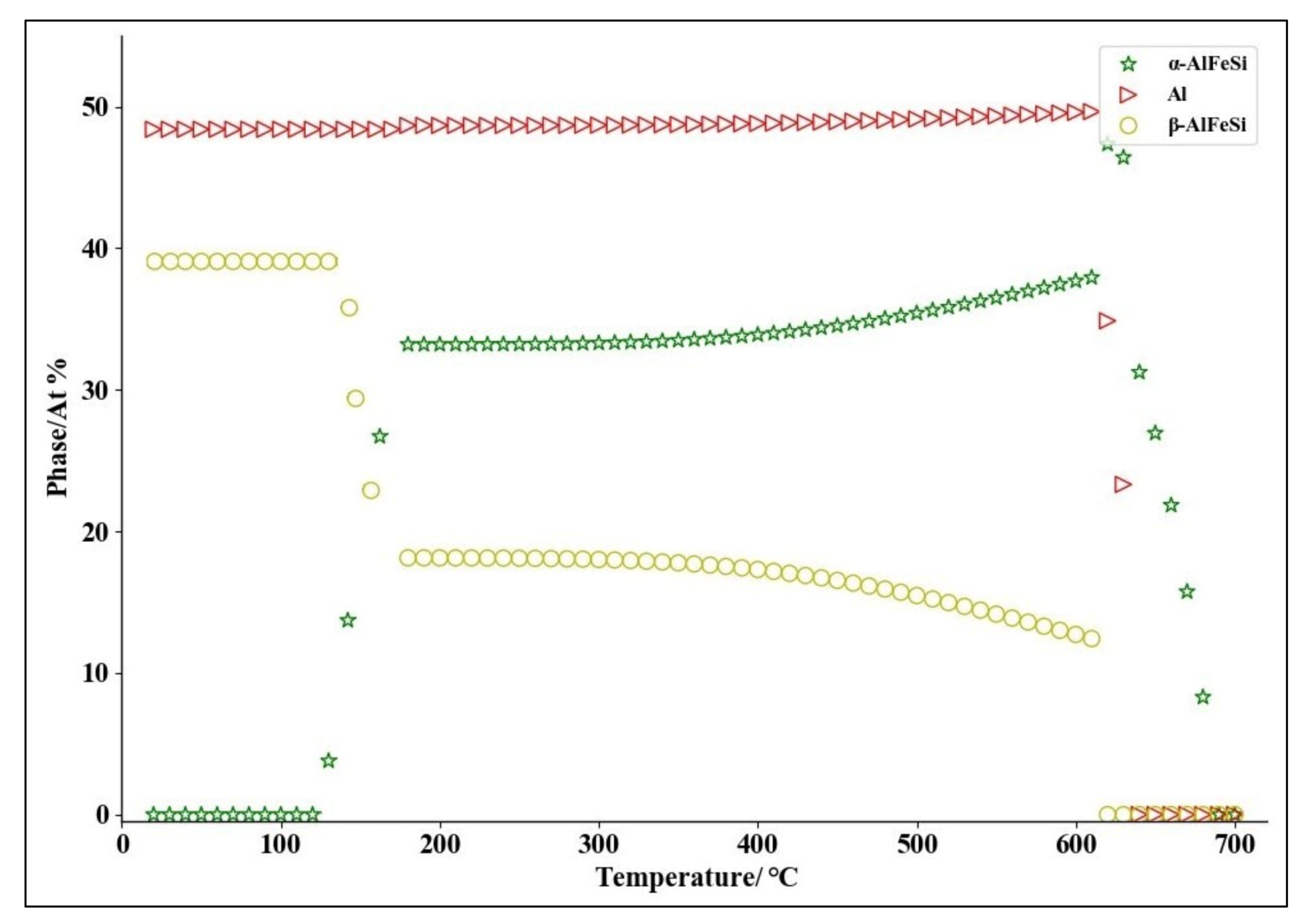
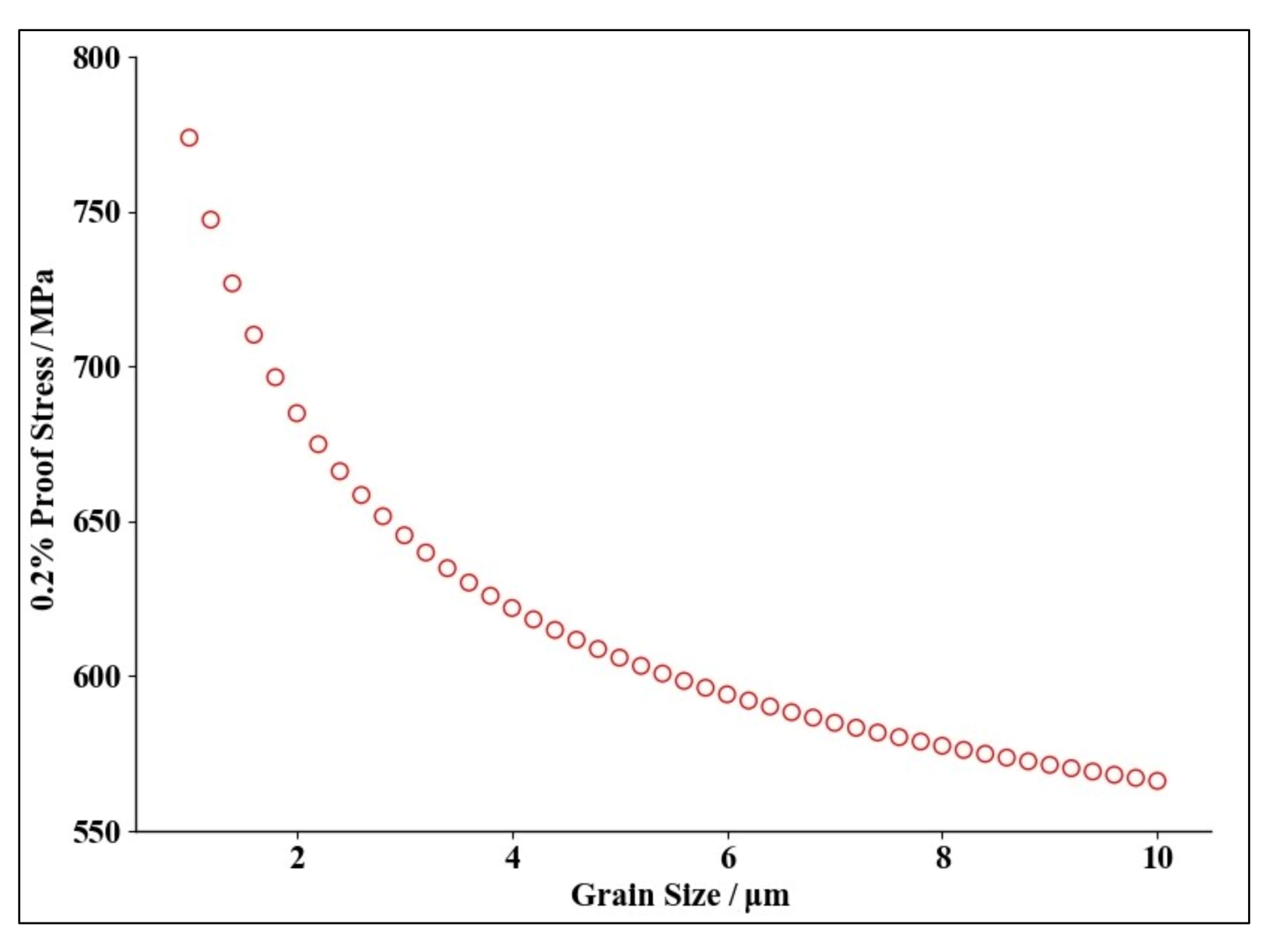
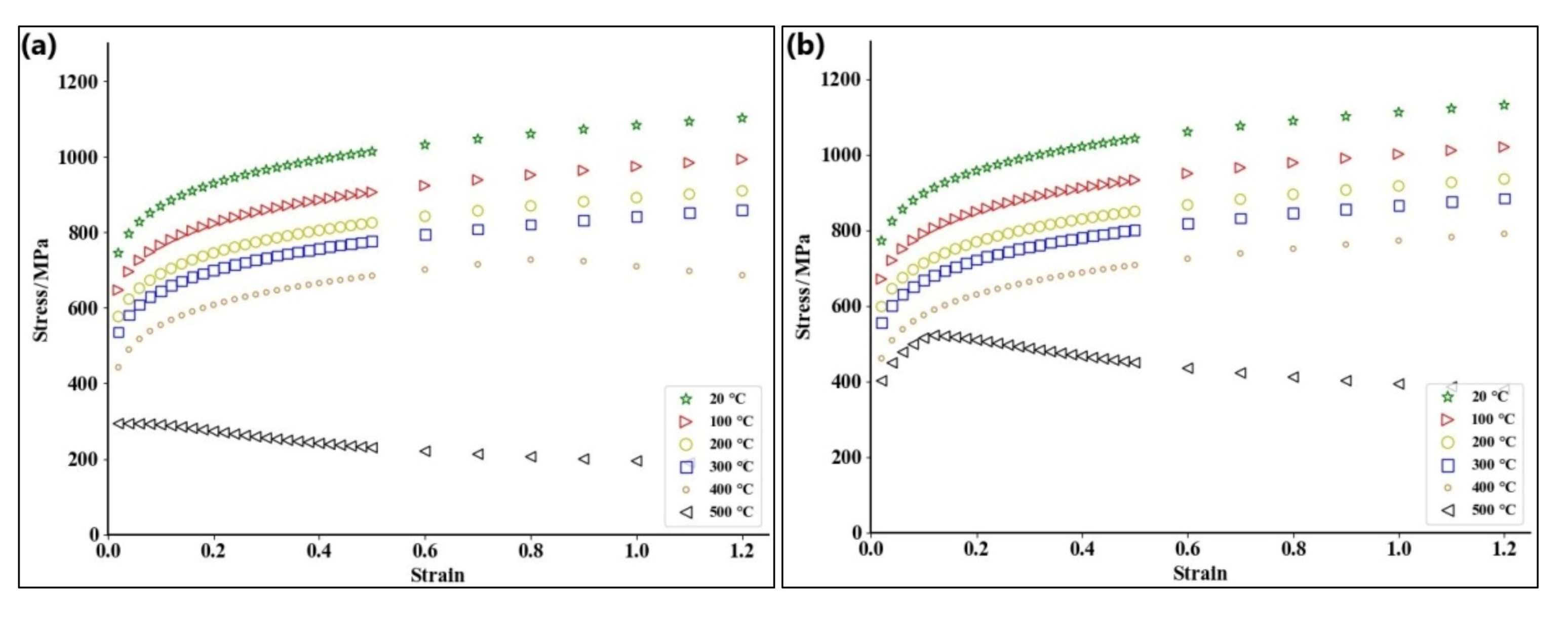
2. Determination of Material Properties of AlFeSi Phase

As mentioned, the material properties for FE simulations include two parts: the physical and thermophysical properties and the mechanical properties. In this paper, JMatPro (Sente Software Company, United Kingdom, The period of validity: 15 April 2021), a phase diagram calculation and performance simulation software, is used to confirm all of the material properties for the AlFeSi phases in Al6061.
Referring to the previous study [15], the white block-like particles (Area I in Figure 1a) and needle-like particles (Area II in Figure 1a) are α-AlFeSi and β-AlFeSi particles, respectively [16], as presented in Figure 1. According to the EDX results, Al86.1Fe8.3Si5.6 is used in this paper to represent the equivalent compositions of AlFeSi phase in Al6061, and its mean grain size is about 2 μm under the analysis of a large number of SEM images.
According to the types and compositions of AlFeSi in Al6061, the temperature-phase transition characteristics of AlFeSi are calculated by JMatPro, as presented in Figure 2. It shows that both the α-AlFeSi and β-AlFeSi begin to dissolve at 620 °C and dissolve completely at 690 °C. Meanwhile, the physical and thermophysical properties of Al86.1Fe8.3Si5.6 are calculated in JMatPro, including density, thermal conductivity, Young’s modulus, Poisson’s ratio, specific heat and thermal expansion coefficient, as shown in Figure 3. From this figure, each curve shows a sudden change when the temperature reaches to 620 °C, which agrees well with the start of dissolution points of α-AlFeSi and β-AlFeSi in Figure 2.
Figure 4 shows the yield strength of the AlFeSi (Al86.1Fe8.3Si5.6) phase under quasi-static conditions (the solid solution temperature is 520 °C and the holding time is 2 h, the aging temperature is 200 °C and aging time is 2 h) from JMatPro. It indicates that the yield strength decreases with the increase of grain size, and it can be found that, the yield strength is 662.33 MPa when the grain size is 2 μm.
During the metal cutting process, under different cutting speeds, the workpiece materials undergo different plastic deformations and present different strain rates. The plastic deformation can be divided into static plastic deformation (strain rates less than 0.00001 s–1), quasi-static plastic deformation (strain rates between 0.00001 and 0.1 s–1) and dynamic plastic deformation (strain rates greater than 0.1 s–1). Figure 5 lists the stress–strain curves of AlFeSi in Al6061 under the condition of quasi-static (strain rates as 0.001 s–1, 0.01 s–1, 0.1 s–1), and dynamic plastic strain (strain rates as 10 s–1, 100 s–1, 1000 s–1) are obtained from JMatPro. It shows that, when the temperature is lower than 400 °C, the stress of AlFeSi increases with the increase of strain. When the temperature is higher than 400 °C, a damage phenomenon of AlFeSi is present even for small strain rates (strain rates less than 0.1 s–1), as shown in Figure 5a,b, while the stress of the AlFeSi phase increases with the increase of strain under a larger strain rate (strain rates greater than 0.1 s–1), as shown in Figure 5c–f.

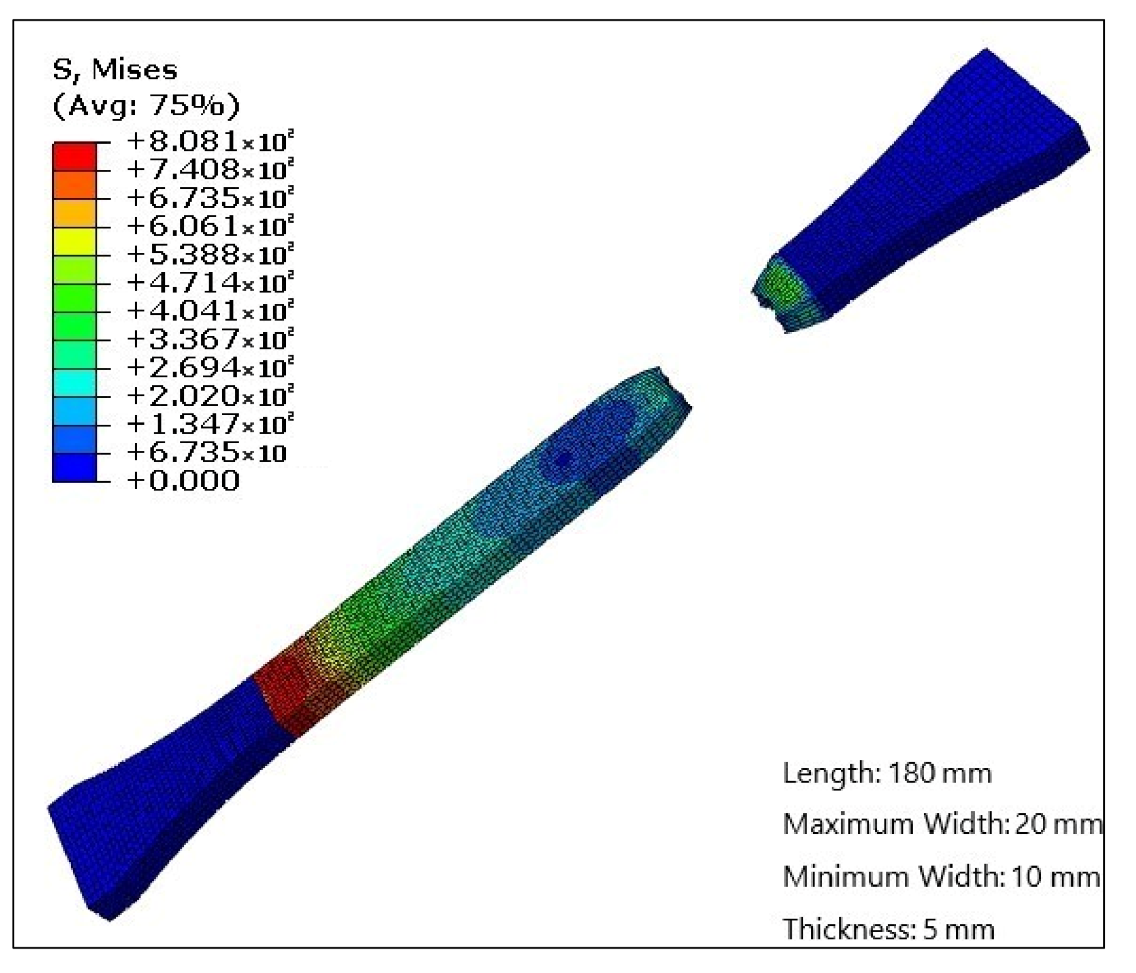
3. Elastoplastic-Damage Model of AlFeSi Phase

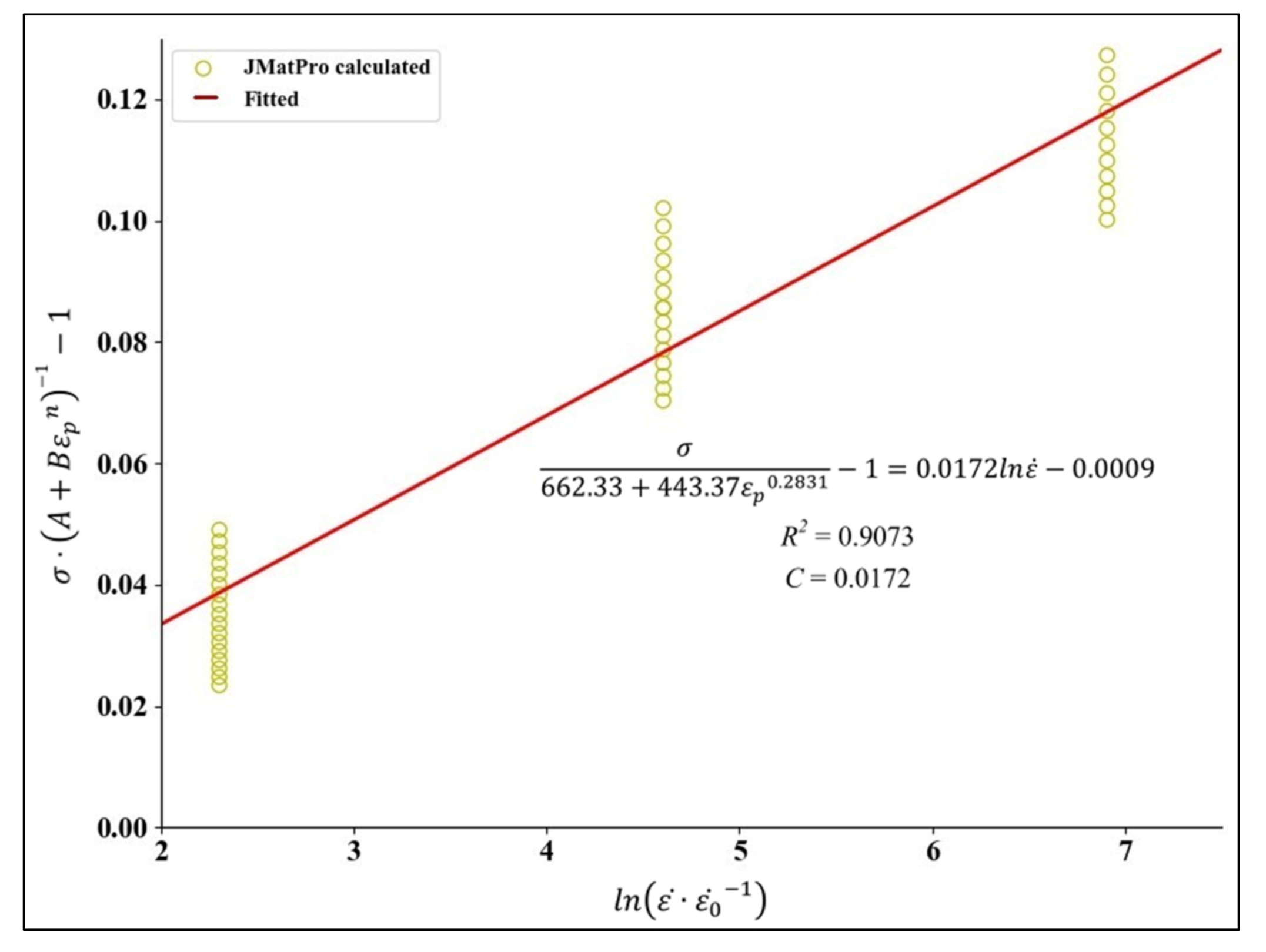
3.1. Solution of Elastoplastic Constitutive Equation

Johnson–Cook elastoplastic constitutive equation (J–C) takes the strain hardening effect, the strain rate effect and the temperature effect of the flow stress into consideration and can be represented as [17,18]
σ = A + B ε p n ( 1 + C ln ε ˙ ε 0 ˙ ) 1 T T 0 T m e l t T 0 m
where, σ is the stress of material,   A is the yield strength, B is the hardening parameter of strain and C is the strengthening parameter of strain rate. ε p is the equivalent plastic strain of the material, ε ˙ is the equivalent plastic strain rate and ε ˙ 0 is the reference strain rate. T 0 is the room temperature and T m e l t is the melting point. n is the hardening index of strain. m refers to the thermal softening parameter.
Based on the stress–strain curves at different temperatures and strain rates of AlFeSi (Figure 5), the unknown parameters (A, B, C, n and m) of J–C elastoplastic constitutive equation can be confirmed by the following steps.
Step 1: Assume at quasi-static room temperature (the strain rates as 0.001 s–1, 0.01 s–1, 0.1 s–1 and the temperature at 20 °C), Equation (1) can be simplified as: σ = A + B ε p n , therefore it can be rewritten as: ln σ A = n · ln ε p + ln B . From Figure 4, when grain size is 2 μm: A = 662.33 MPa. Additionally, the values of factors (A, B, n) can be confirmed, as shown in Figure 6.
Step 2: Assume at dynamic normal temperature (the strain rates as 10 s–1, 100 s–1, 100 s–1 and the temperature at 20 °C), Equation (1) can be simplified as: σ = A + B ε p n 1 + C · ln ε ˙ / ε 0 ˙ , therefore can be rewritten as: σ / A + B ε p n 1 = C · ln ε ˙ / ε 0 ˙ . Referring to [19]: ε ˙ 0 = 1 , the value of C can be confirmed, see Figure 7.
Step 3: Assume at quasi-static high temperature (the strain rates as 0.001 s–1, 0.01 s–1, 0.1 s–1 and the temperature higher than 20 °C), Equation (1) can be simplified as σ = A + B ε p n 1 T T 0 ) / ( T m e l t T 0 m and be changed as: ln 1 σ / A + B ε p n = m · ln T T 0 / T m e l t T 0 . T 0 = 20 °C and T m e l t = 690 °C. Due to the small cutting depth and low cutting speed in Ultra-precision machining (UPM), the cutting-induced heat generation is less and the temperature T can be set as: 50 °C, 100 °C, 150 °C and 200 °C, and m can be confirmed, as shown in Figure 8.

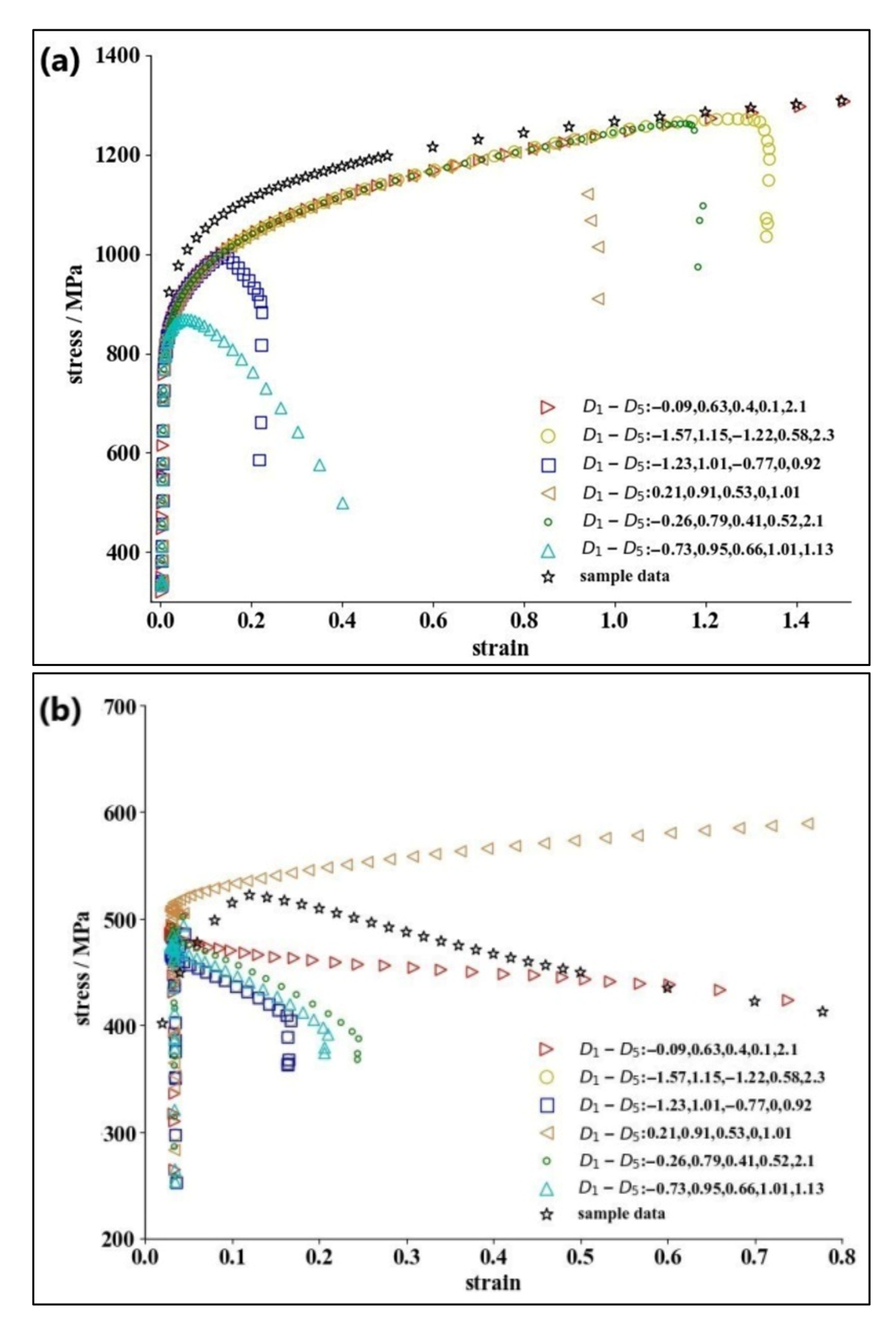
3.2. Solution of Damage Constitutive Equation

Johnson et al. [17,18] proposed a fracture criterion of the material with the consideration of the effects of stress triaxiality, strain, strain rate and temperature on the material failure:
D = Δ ε f ε f ¯
Meanwhile, the material breaks when the equivalent effect increment ( Δ ε f ) is equal to the failure strain ( ε f ¯ ) ( D = 1), where Δ ε f can be calculated by Equation (3).
Δ ε f   = ε f = D 1 + D 2 exp η D 3 ( 1 + D 4 ln ε ˙ ε 0 ˙ ) ( 1 + D 5 T T 0 T m e l t T 0 )
where, D 1 D 5 are fitting coefficients, η is the stress triaxiality.
The damage constitutive equation of the AlFeSi phase is based on the J–C damage constitutive equation. To obtain the fracture stress ( σ k ), the strain and the strain rate of AlFeSi, multi-group dynamic rotating disk impact tensile experiments at room temperature and high-temperature environment are needed. In this paper, an FEM simulation approach is proposed to calculate the damage stress–strain curves of the AlFeSi phase under each group of D 1 D 5 parameters, which will be compared with those from JMatPro to determine the convergence of the calculation.
In general, to obtain the five coefficients ( D 1 D 5 ) and to guarantee the validity of experimental results, several groups of quasi-static stretching experiments and dynamic rotary disk impact stretching experiments need to be conducted at different temperatures to evaluate the fracture stress, strain and strain rate of the tested materials. The experimental process is not only time-consuming but also requires a large number of material samples with consistent material properties, especially for the unknown materials (Al86.1Fe8.3Si5.6). In this paper, a method based on FE simulation and JMatPro is proposed to solve the coefficients ( D 1 D 5 ) of the material damage equation, which is scheduled as follows:
Step 1: Conduct FE simulations to achieve the stress–strain curve of AlFeSi at different temperatures and different strain rates by Abaqus software 2019 (Dassault SIMULIA, France, The period of validity: 20 June 2021) and Python (Version 3.5, accessed on 15 February 2021). Figure 9 shows the FE simulation results for the tensile fracture damage of AlFeSi, in which the mesh grid cell type is C3D8RT and the total element grid of the model is 12,870.
Step 2: Set the ambient temperature as 20 °C, 50 °C, 100 °C, 200 °C, 300 °C, 400 °C and 500 °C, the default value of D 1 D 5 as 1 and the step size ( S k ) as 0.5, 0.1, 0.05 and 0.01. Table 1 lists the boundary conditions and the total step size of the model at 20 °C.
Step 3: Calculate the five parameters ( D 1 D 5 ) as: D i = D i ± S k · j , and   k = 1 ,   2 ,   3 ,   4 ,   i = 1 ,   2 ,   3 ,   4 ,   5 ,   j = 0 ,   1 ,   2 ,   3 ,   4 . The value of the step size ( S k ) ranges from the largest value (0.5) to the smaller one (0.1), and final to the smallest one (0.01).
Step 4: Achieve an optimized combination of all five parameters ( D 1 D 5 ) with the smallest mean square error ( δ ):
min δ = min 1 n i = 1 i = n x i y i 2 1 n i = 1 i = n y i
where, x i = f i ,   y i = g i represent the damage stress–strain curves of AlFeSi from JMatPro and FE simulation, respectively.
Figure 10a,b presents the calculation results of D 1 D 5 under two different conditions and the mean square errors in Figure 10a,b are 0.023 and 0.029, respectively.

4. Experimental Verification

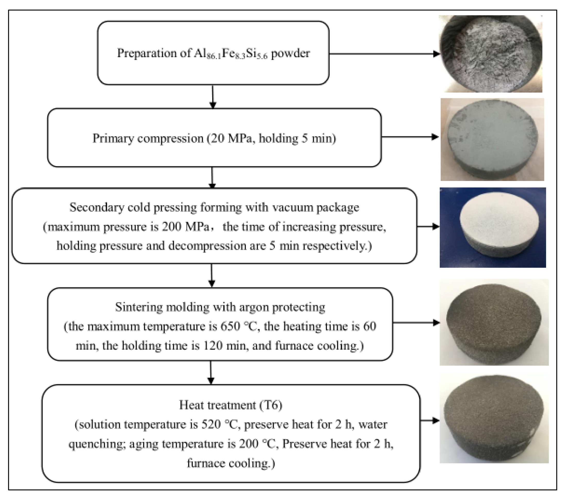
4.1. Material Preparation for AlFeSi

To verify the proposed method for the material properties, AlFeSi (Al86.1Fe8.3Si5.6) is prepared and the material properties are examined to compare with the calculation results. The material preparation of AlFeSi is scheduled as (Figure 11): (1) Dissolving the pure aluminum at 750 °C; (2) increasing the proportion of alloy composition to meet the national standard limit of AlFeSi; (3) casting the solution into ingots; (4) hot press molding with heating temperature at 400 °C and pressure at 200 MPa; and (5) T6 treatment.

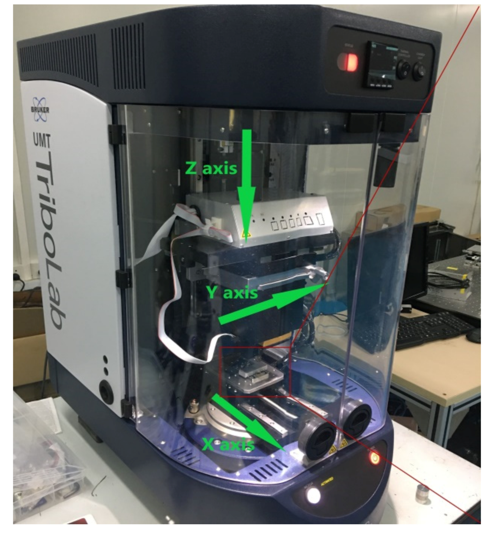
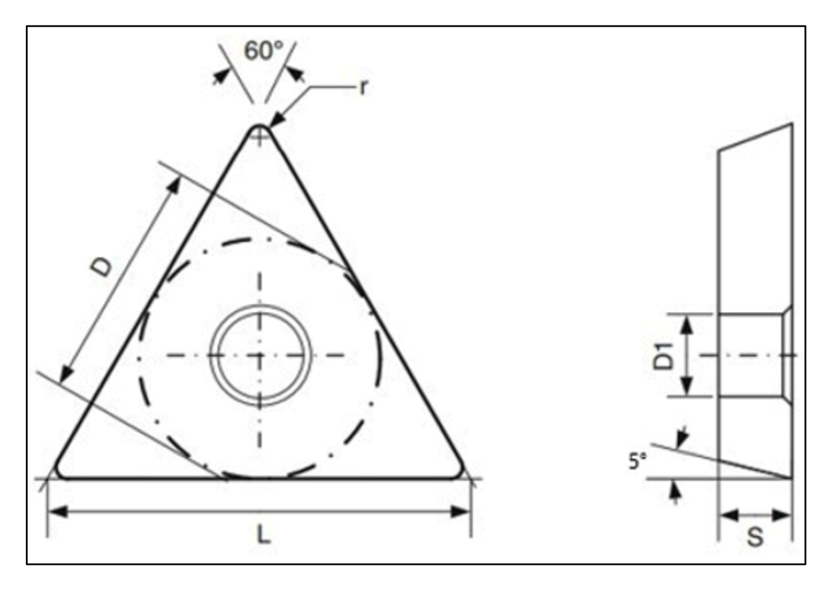
4.2. Scratch Experiment

Scratch experiments are carried out to examine the prepared AlFeSi at room temperature (20 °C) on Bruker UMT Tribolab (from Berlin, Germany, Figure 12). The X-axis speed and the scratch length are set as 5 mm/s and 10 mm, respectively. The Z-axis loads are changed as 1 N, 2 N, 3 N and 4 N. Figure 13 shows the geometric parameters of the tungsten carbide (WC) cemented carbide tool (Rockwell hardness 93). After the scratch test, the polished surface and the scratch depth are evaluated by an optical profiler (BRUKER Contour GT-X, from Berlin, Germany), as shown in Figure 14.

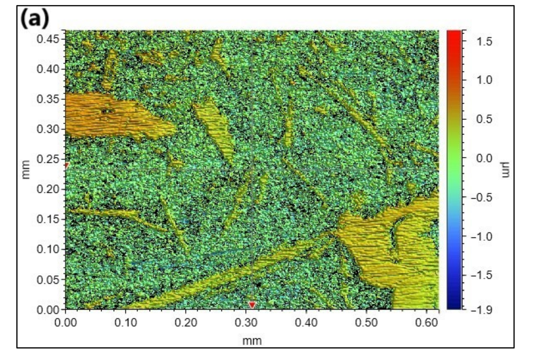
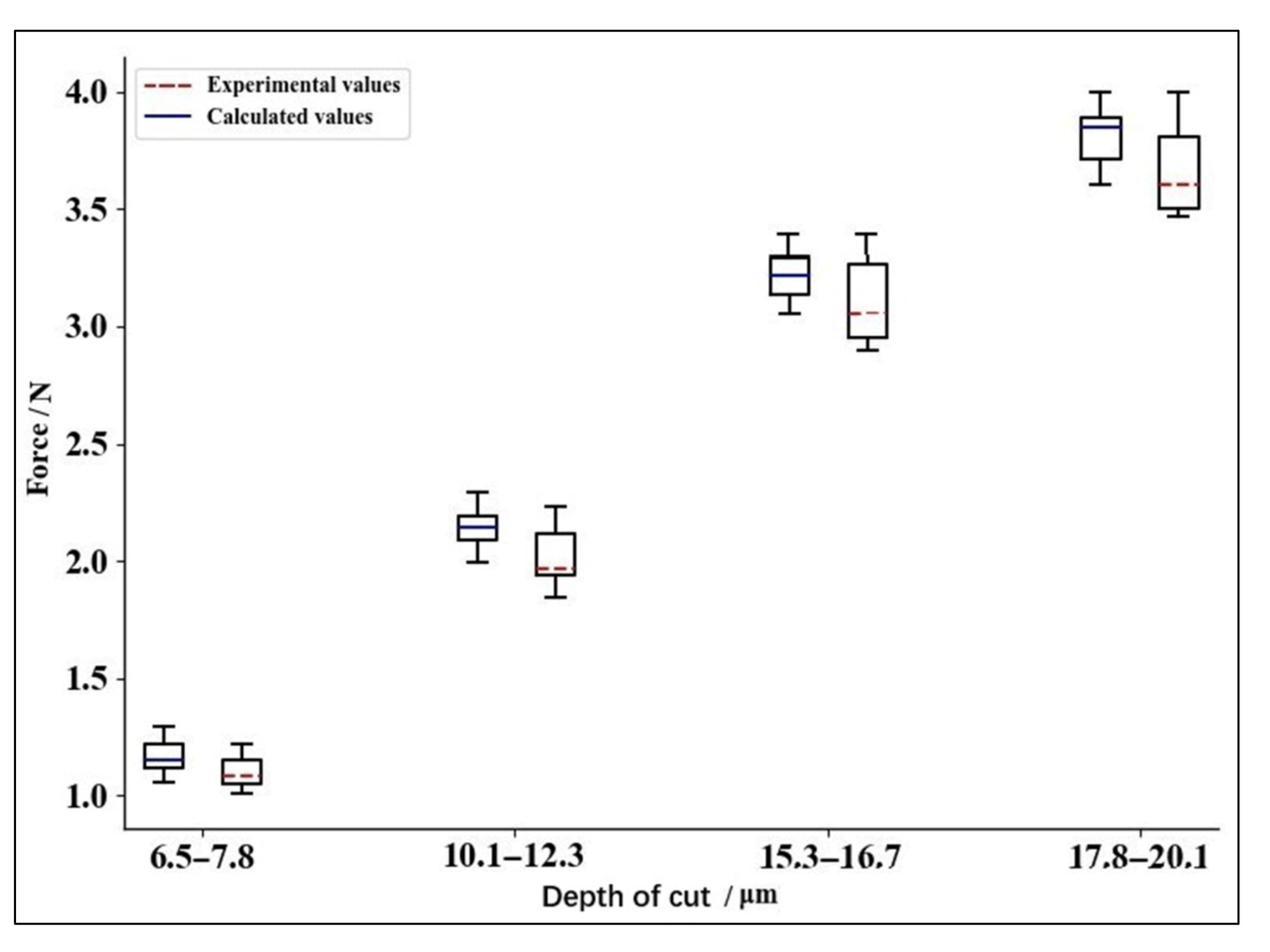
4.3. Results and Discussions

Based on the calculation results of the AlFeSi material properties from the proposed method in this paper and a well-established elastoplastic-damage model, the FE model of the scratch test for AlFeSi is built by Abaqus software (as shown in Figure 15). The mesh element type is C3D8RT and the total grid quantity is 129,510. Table 2 lists all of the material properties for the WC cemented carbide tool used in FE simulation [20]. The boundary conditions of the FE model are set to the same parameters of the scratch experiment.
Figure 16 shows the comparison if the X-axis scratching force between the experiment and the simulation results from FE model. From this figure, as the scratch depth increases from 6.5 to 20 μm, both the simulated scratch forces and the experimental increase, and the simulated forces are close to the experimental ones. The probability of the X-axis scratch forces errors being less than 6.5% is 98% between FE simulation results and the scratch experiment. Moreover, the fluctuation ranges of the simulated forces and the experimental results increase with the increase of scratch depth, while the former is smaller than the latter. All of these infer that the method proposed in this study can be applied to confirm that all the parameters for AlFeSi and the developed elastoplastic-damage model of AlFeSi phase are feasible and effective.

5. Conclusions

This paper performs an investigation into the development of an elastoplastic-damage model for AlFeSi phase in Al6061. Based on the FE method and JMatPro, a new method is proposed in this study to efficiently calculate all of the parameters of J–C elastoplastic constitutive equation and J–C constitutive damage failure equation for AlFeSi. Al86.1Fe8.3Si5.6 is prepared and the scratch experiments are conducted to study the scratch force error between FE simulation results and the scratch experiment. It shows that the errors of scratch forces between the simulation and experimental results are less than 6.5%.
Therefore, this study not only helps to propose a new method for studying the properties of a new material, but also contributes to providing a better understanding for the mechanisms of surface generation and material removal in ultra-precision machining of Al-Mg-Si alloys.

Author Contributions

Conceptualization, H.W. and S.W.; methodology, H.W. and S.W.; validation, H.W., T.Z. and S.W.; formal analysis, H.W., T.Z., W.D. and S.W.; investigation, H.W. and S.W.; data curation, H.W., T.Z., W.D., J.Y. and S.W.; writing—original draft preparation, H.W.; writing—review and editing, S.W.; supervision, S.W. All authors have read and agreed to the published version of the manuscript.

Funding

This research was funded by the National Natural Science Foundation of China, grant number 51975128.

Data Availability Statement

All data, models, and code generated or used during the study appear in the submitted article.

Conflicts of Interest

The authors declare no conflict of interest.

References

  1. Khan, M.; Ud Din, R.; Wadood, A.; Syed, W.H.; Akhtar, S.; Aune, R.E. Effect of Graphene Nanoplatelets on the Physical and Mechanical Properties of Al6061 in Fabricated and T6 Thermal Conditions. J. Alloys Compd. 2019, 790, 1076–1091. [Google Scholar] [CrossRef]
  2. Sekhar, A.P.; Mandal, A.B.; Das, D. Mechanical Properties and Corrosion Behavior of Artificially Aged Al-Mg-Si Alloy. J. Mater. Res. Technol. 2020, 9, 1005–1024. [Google Scholar] [CrossRef]
  3. Wang, S.; To, S.; Chen, X.; Chen, X. An Investigation on Surface Finishing in Ultra-Precision Raster Milling of Aluminum Alloy 6061. Proc. Inst. Mech. Eng. Part B J. Eng. Manuf. 2015, 229, 1289–1301. [Google Scholar] [CrossRef]
  4. Zhang, S.J.; To, S.; Wang, S.J.; Zhu, Z.W. A Review of Surface Roughness Generation in Ultra-Precision Machining. Int. J. Mach. Tools Manuf. 2015, 91, 76–95. [Google Scholar] [CrossRef]
  5. Zhang, W.; Cao, Y.; Wang, J.; Gao, Y.; Zhou, M. Anisotropy Research of Ultra-Precision Machining on KDP Crystal. In Proceedings of the SPIE 7655, 5th International Symposium on Advanced Optical Manufacturing and Testing Technologies: Advanced Optical Manufacturing Technologies, Dalian, China, 6 October 2010; Volume 7655. [Google Scholar] [CrossRef]
  6. Zong, W.J.; Huang, Y.H.; Zhang, Y.L.; Sun, T. Conservation Law of Surface Roughness in Single Point Diamond Turning. Int. J. Mach. Tools Manuf. 2014, 84, 58–63. [Google Scholar] [CrossRef] [Green Version]
  7. He, C.L.; Zong, W.J.; Sun, T. Origins for the Size Effect of Surface Roughness in Diamond Turning. Int. J. Mach. Tools Manuf. 2016, 106, 22–42. [Google Scholar] [CrossRef]
  8. Wang, M.; Wang, W.; Lu, Z. Anisotropy of Machined Surfaces Involved in the Ultra-Precision Turning of Single-Crystal Silicon—a Simulation and Experimental Study. Int. J. Adv. Manuf. Technol. 2012, 60, 473–485. [Google Scholar] [CrossRef]
  9. Cheung, C.F.; Chan, K.C.; To, S.; Lee, W.B. Effect of Reinforcement in Ultra-Precision Machining of Al6061/SiC Metal Matrix Composites. Scr. Mater. 2002, 47, 77–82. [Google Scholar] [CrossRef]
  10. Simoneau, A.; Ng, E.; Elbestawi, M.A. Surface Defects during Microcutting. Int. J. Mach. Tools Manuf. 2006, 46, 1378–1387. [Google Scholar] [CrossRef]
  11. Harlow, D.G.; Nardiello, J.; Payne, J. The Effect of Constituent Particles in Aluminum Alloys on Fatigue Damage Evolution: Statistical Observations. Int. J. Fatigue 2010, 32, 505–511. [Google Scholar] [CrossRef]
  12. Wang, S.J.; To, S.; Cheung, C.F. Effect of Workpiece Material on Surface Roughness in Ultraprecision Raster Milling. Mater. Manuf. Process. 2012, 27, 1022–1028. [Google Scholar] [CrossRef]
  13. Wang, S.J.; Chen, X.; To, S.; Ouyang, X.B.; Liu, Q.; Liu, J.W.; Lee, W.B. Effect of Cutting Parameters on Heat Generation in Ultra-Precision Milling of Aluminum Alloy 6061. Int. J. Adv. Manuf. Technol. 2015, 80, 1265–1275. [Google Scholar] [CrossRef]
  14. Wang, S.; Xia, S.; Wang, H.; Yin, Z.; Sun, Z. Prediction of Surface Roughness in Diamond Turning of Al6061 with Precipitation Effect. J. Manuf. Process. 2020, 60, 292–298. [Google Scholar] [CrossRef]
  15. Wang, H.; Zhang, T.; Wang, S.; To, S. Characterization of the Friction Coefficient of Aluminum Alloy 6061 in Ultra-Precision Machining. Metals 2020, 10, 336. [Google Scholar] [CrossRef] [Green Version]
  16. Lan, X.; Li, K.; Wang, F.; Su, Y.; Yang, M.; Liu, S.; Wang, J.; Du, Y. Preparation of millimeter scale second phase particles in aluminum alloys and determination of their mechanical properties. J. Alloys Compd. 2019, 784, 68–75. [Google Scholar] [CrossRef]
  17. Johnson, G.R.; Cook, W.H. A constitutive model and data for metals subjected to large strains, high strain rates and high temperatures. In Proceedings of the 7th International Symposium on Ballistics, The Hague, The Netherlands, 19–21 April 1983; pp. 541–547. [Google Scholar]
  18. Johnson, G.; Cook, W. Fracture Characteristics of Three Metals Subjected to Various Strains, Strain Rates, Temperatures and Pressures. Eng. Fract. Mech. 1985, 21, 31–48. [Google Scholar] [CrossRef]
  19. Akram, S.; Jaffery, S.H.I.; Khan, M.; Fahad, M.; Mubashar, A.; Ali, L. Numerical and Experimental Investigation of Johnson–Cook Material Models for Aluminum (Al6061-T6) Alloy Using Orthogonal Machining Approach. Adv. Mech. Eng. 2018, 10, 1687814018797794. [Google Scholar] [CrossRef] [Green Version]
  20. Asad, M.; Ijaz, H.; Khan, M.A.; Mabrouki, T.; Saleem, W. Turning Modeling and Simulation of an Aerospace Grade Aluminum Alloy Using Two-Dimensional and Three-Dimensional Finite Element Method. Proc. Inst. Mech. Eng. Part B J. Eng. Manuf. 2014, 228, 367–375. [Google Scholar] [CrossRef]
Figure 1. Chemical composition of AlFeSi in Al6061 from the previous study [15]: (a) SEM of the Al6061 samples; (b) EDX results of the Al6061 samples (Atomic %).
Metals 11 00954 g001
Figure 2. The temperature-phase transition characteristics of α-AlFeSi and β-AlFeSi from JMatPro.
Metals 11 00954 g002
Figure 3. The characterization results of (a) density; (b) thermal conductivity; (c) Young’s modulus; (d) Poisson’s ratio; (e) specific heat; (f) thermal expansion coefficient.
Metals 11 00954 g003
Figure 4. The yield strength of AlFeSi phase under quasi-static conditions.
Metals 11 00954 g004
Figure 5. The stress–strain curve of AlFeSi phase under different strain rates: (a) strain rate 0.001 s–1; (b) strain rate 0.01 s–1; (c) strain rate 0.1 s–1; (d) strain rate 10 s–1; (e) strain rate 100 s–1; (f) strain rate 1000 s–1.
Metals 11 00954 g005aMetals 11 00954 g005b
Figure 6. Solutions of three parameters ( A , B and   n ).
Metals 11 00954 g006
Figure 7. Solution of parameter C .
Metals 11 00954 g007
Figure 8. Solution of parameter m .
Metals 11 00954 g008
Figure 9. FE simulated tensile fracture damage of AlFeSi phase.
Metals 11 00954 g009
Figure 10. The stress–strain curve of AlFeSi phase with D 1 D 5 : (a) strain rate of 1000 s–1, temperature of 20 °C; (b) strain rate of 0.01 s–1, temperature of 500 °C.
Metals 11 00954 g010
Figure 11. Preparation of the AlFeSi phase.
Metals 11 00954 g011
Figure 12. The scratch experiment of AlFeSi phase.
Metals 11 00954 g012aMetals 11 00954 g012b
Figure 13. The parameters of the scratch tool (L = 10.5 mm, D = 6.01 mm, D1 = 2.56 mm, S = 2.74 mm, r = 0.4 mm).
Metals 11 00954 g013
Figure 14. (a) The measured surface and (b) scratch of AlFeSi sample from the optical profiler.
Metals 11 00954 g014aMetals 11 00954 g014b
Figure 15. FE simulation model for the scratch experiment of AlFeSi phase.
Metals 11 00954 g015
Figure 16. Comparison between FE simulation results and the scratch experiment.
Metals 11 00954 g016
Table 1. The parameters of tensile fracture damage FEM for AlFeSi phase at 20 °C.
Strain Rate/s−1Force/NThe Total Time/s
0.00160,0000.25
0.0190,0000.15
0.1120,0000.1
10650,0000.025
1006,000,0000.005
1000200,000,0000.001
Table 2. The parameters of WC cemented carbide tool (20 °C).
Density.
(ton/mm3)
Young’s Modulus
(MPa)
Poisson’s RatioSpecific Heat
(mJ/(ton·°C))
Coefficient of Thermal Expansion
(1/°C)
Thermal Conductivity
(W/(m·°C))
11.9 × 109534,0000.220.4 × 1094.7 × 10650
Publisher’s Note: MDPI stays neutral with regard to jurisdictional claims in published maps and institutional affiliations.

