Article

Weldability and Damage Evaluations of Fresh-to-Aged Reformer Furnace Tubes

1
School of Mechanical and Power Engineering, Nanjing Tech University, Nanjing 211816, China
2
Key Laboratory of Design and Manufacture of Extreme Pressure Equipment, Nanjing 211816, China
3
School of Mechanical Engineering, Inner Mongolia University of Science & Technology, Baotou 014010, China
*
Author to whom correspondence should be addressed.
Metals 2021, 11(6), 900; https://doi.org/10.3390/met11060900
Submission received: 6 May 2021 / Revised: 20 May 2021 / Accepted: 22 May 2021 / Published: 31 May 2021
(This article belongs to the Special Issue High-Temperature Behavior of Metals)

Abstract

:
The microstructures and tensile properties of fresh and aged reformer furnace tubes and a fresh-to-aged welded joint were investigated to assess the weldability of fresh-to-aged reformer furnace tubes. Damage evaluation of the fresh-to-aged welded joint was also carried out using the modified Kachanov–Rabotnov model. The experimental results showed that M7C3 carbide transforms into M23C6 carbide and secondary carbides precipitate in the matrix after aging treatment. With continuous exposure, the interdendritic precipitates coalesced and coarsened and the number of secondary carbides reduced gradually. Microdefects were absent in the fresh-to-aged welded joint, and the tensile properties of the welded joint were close to the as-cast alloy, which confirms the weldability of fresh-to-aged furnace tubes. According to the results of the simulation, stress redistribution occurred during the creep process and the peak damage of the welded joint was located in the aged tube. The maximum damage of the fresh-to-aged welded joint reached 34.01% at 1.5 × 10⁵ h.

Graphical Abstract

1. Introduction

A steam reformer furnace tube is the key component for producing hydrogen and carbon monoxide in a steam reformer furnace [1,2,3]. The designed lifetime of reformer furnace tubes is 105 h according to API 530 [4]. Due to the elevated temperature and inner pressure, the tube mainly suffers from creep damage under service conditions, which contributes greatly to the lifetime of the furnace tube [2,5,6,7]. Furthermore, the outer surface of the tube is also subjected to oxidation damage [8,9]. Therefore, it is necessary to develop a heat resistance alloy to withstand severe service conditions so as to extend the lifetime of the furnace tube. In the past decades, heat-resistant HP40Nb (25Cr35Ni1Nb) alloy has been developed by adding a small amount of niobium to HP40 alloy [10,11,12,13]. The alloy is being widely used for steam reformer furnace tubes due to superior oxidation and creep resistance as well as mechanical properties at elevated temperatures, including strength and toughness. Actually, the wall temperature in the whole furnace tube is heterogeneous, which leads to inhomogeneous damage distribution [7]. The maximum temperature in the lower segment can reach as high as 950 °C, and the microstructures are seriously deteriorated after long-term thermal exposure. The tubes should be replaced for the safety of steam reformers. Nevertheless, the damage level in the upper segment is comparatively lower and the upper tubes can continue to service. Additionally, the reformer tubes comprise a significant fraction of the petrochemical reforming plants cost, due to the high alloy content [7,14]. Therefore, there is a cost-driven motivation of local repairment in contrast to replacing the entire set of tubes, where the lower portion with the deteriorated microstructures is replaced with an as-cast tube [7,15]. Unfortunately, welding as-received tubes to aged ones may bring about weldability issues due to the diversities in microstructures and mechanical properties.
As is known to all, the microstructures of as-cast HP40Nb alloy are composed of a supersaturated austenite matrix and interdendritic primary carbides (M7C3, M23C6, and NbC). The primary NbC and M7C3 carbides transform into the G phase [3,9,10,11,16] and M23C6 carbide after thermal exposure, respectively [5,11,16,17]. The secondary M23C6 carbide precipitates in the matrix. Meanwhile, the inter- and intradendritic phases are coarsen and the morphology of precipitates changes gradually with continuous exposure. The phase transformation and precipitate coarsening both result in a reduction in mechanical properties of the alloy, leading to low weldability. Studies suggest that the G phase can decrease the creep strength [11], while the weldability is not affected and is correlated to the coarsening precipitates [14]. In terms of the weldability of the component, there are several assessment methods. Weldability can be evaluated by some standard weldability tests and the corresponding test specimen, including a Tekken test specimen and a CTS specimen [18,19]. After welding, non-destructive tests are conducted, including visual, penetrant, radiographic, and ultrasonic tests. If welding cracks and other defects are absent, further destructive tests are performed, such as tensile, bending, impact, and metallographic tests. As mentioned above, the microstructures of the reformer tube change with continuous service exposure and the degradation of the microstructure leads to a reduction in mechanical properties, especially tensile properties. Therefore, weldability can be primarily judged by the absence of post-welding macro-cracks for an HP40Nb reformer tube [20,21]. In addition, the elongation of aged tubes at room temperature equal to or greater than 4% are considered to be weldable according to technical guidelines [14,22]. Therefore, the weldability of the reformer tube can be assessed by non-destructive tests followed by destructive tests, including microstructural characterization and tensile tests. Although investigations on the weldability of a serviced reformer tube are sufficient, studies on the weldability of fresh-to-aged reformer tubes in view of microstructures and mechanical properties are rare. Additionally, the damage evaluation of the fresh-to-aged welded joint should also be implemented to predict the lifetime of reformer tubes after local repairment. For the life prediction of components controlled by creep, it is necessary to analyze their creep behavior and evaluate the damage evolution. Continuum damage mechanics is usually used to reflect creep damage and to describe creep deformation behavior, which can be categorized into empirical-based models [23,24,25,26,27] and physical-based models [28,29,30,31]. Empirical-based damage models define a single damage variable to quantify the average loss of strength, while physical-based models usually couple different damage variables into a sinh function to study the influence of different damage mechanisms on creep deformation. The empirical-based Kachanov–Robatnov (KR) model [23,24] has been widely used owing to its accurate prediction and the available parameters. In our previous investigation [15], the damage evolution of the service furnace tube was deduced based on the modified KR model [26]. However, the issues in damage assessment of fresh-to-old reformer tubes have not been investigated.
In this paper, accelerated aging treatments were carried out for as-cast HP40Nb alloy to simulate the service microstructure. The weldability evaluation of fresh-to-aged reformer tubes was conducted based on their microstructures and tensile properties. Furthermore, the damage evolution of fresh-to-aged welded joints was also predicted using the modified Kachanov–Robatnov damage model based on the creep data of HP40Nb alloy.

2. Materials and Experimental Section

The material investigated in this study is centrifugally cast HP40Nb alloy. The outer diameter and wall thickness are 126 and 13 mm, respectively. The chemical composition of the as-cast HP40Nb alloy was measured using an optical emission spectrometer (OES) and is shown in Table 1. Long-term thermal exposure experiments on the as-cast alloy samples were conducted at 990 °C with different aging periods (500, 2000, and 4000 h) to model the microstructural evolution in long-term service exposure. The relationship between aging time and operating time according to the Larson Miller equation is illustrated in Table 2 [32]. To study the weldability and damage evolution of the upper reformer tube at 900 °C after local repairment, an aged tube (990 °C, 2000 h) corresponding to the service tube for 1.2 × 10⁵ h at 900 °C was selected to be welded to the original tube by Gas Tungsten Arc Welding (GTAW) using a TIG 35CW filler metal. The lengths of the reformer tubes used for welding were both 150 mm. The chemical composition of the filler metal is also present in Table 1. A V-joint groove with a 30° half-angle and a root opening of 2 mm were used. The welding current and voltage were 130 A and 10–18 V, respectively. The welding speed was about 9 cm/min. Therefore, the maximum heat input was calculated as 1.56 kJ/mm. Argon with 99.9% purity was used as a shielding and backing gas with a 14 L/min flow. The preheating temperature and the maximum interpass temperature were both 150 °C. Six filling passes were applied to fill the seam. Dye penetration inspection and radiographic testing were carried out in sequence after covering welding. The results suggested that macro-cracks and other welding defects were absent in the fresh-to-aged welded joint. Therefore, further microstructural characterization and mechanical tests can be implemented to assess the weldability of fresh-to-aged reformer tubes.
To identify the precipitates in the as-cast and aged alloys, the precipitates were extracted from the matrix using Berzelius solution [33]. The extracted residues were identified using a Rigaku Smartlab diffractometer at 40 kV and 30 mA from 30° to 60° with a step size of 0.02°. The microstructural morphology of samples with various aging times was observed by Zeiss AXIO Imager A1m optical microscopy (OM) (Oberkochen, Germany) and Zeiss Ultra 55 field emission–scanning electron microscopy (FE-SEM) (Oberkochen, Germany). Element chemical analysis was conducted using an energy-dispersive spectrometer (EDS). The microstructures and microdefects of the fresh-to-aged welded joint were also detected using OM. The specimens for OM observation and FE-SEM examination were prepared by standard metallographic methods, such as cutting, grinding, and polishing, and then the samples were tested after electrolytic etching at 0.5 A for 4 s using saturated oxalic acid solution.
The tensile properties of the as-cast alloy, aged alloy (990 °C, 2000 h), and fresh-to-aged welded joint were determined by tensile tests at room and elevated (950 °C) temperatures. The tensile tests at room and elevated temperatures were conducted according to the Chinese standards GB/T 228.1-2010 and GB/T 228.2-2015, respectively, performed on a Hydraulic Servo 4830 instrument (Kyoto, Japan) equipped with a 100 KN load cell and a multifunctional Hydraulic Servo MTS Landmark 370.10 machine (Minneapolis, MI, USA), respectively. Monotonic creep tests of the as-cast alloy, aged alloy, and fresh-to-aged welded joint were conducted on a mechanical CTM304 creep-testing machine (Shenzhen, China) in a wide range of stresses at 950 °C, and creep tests were conducted according to the standard GB/T 2039-2012. The specimens for tensile and creep tests were taken from the middle of the furnace tube. The configuration and dimensions of the specimen for creep tests are shown in Figure 1.

3. Experimental Results and Discussion

3.1. Precipitate Identification

XRD patterns of the extracted powder of the as-cast and aged HP40Nb alloy samples are shown in Figure 2. In the as-cast condition, the main precipitates of the alloy were niobium carbide (NbC) and chromium-rich carbides (M7C3 and M23C6). Niobium first combines with carbon, forming NbC at higher temperature during solidification [11]. The atomic ratio of Nb to C acts as the driving force for the formation of NbC. A higher value of the atomic ratio leads to the greater driving force for forming NbC. The value (0.20) of the ratio lower than 0.5 in HP40Nb alloy is insufficient for Nb to combine with all the free carbon to form NbC [34]. As a result, chromium attracts the free carbon left in the matrix to form chromium carbides at lower temperature during solidification. Due to the high cooling rate, M7C3 carbide cannot transform into M23C6 carbide completely. Hence, M7C3 and M23C6 carbides coexist in the as-cast alloy. Compared with fresh material, the diffraction intensity of the M7C3 peaks was not seen on the X-ray spectrum in the aging state, which indicates that M7C3 carbide transforms to M23C6 carbide after long-term exposure. Moreover, the NbC peaks that still existed on the X-ray spectrum and in other phases, such as the G phase, were not detected in the aged alloy.

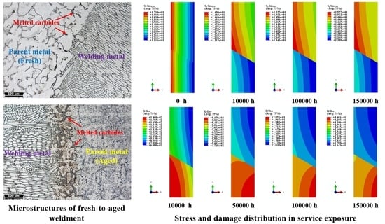
3.2. Microstructural Characterization

Figure 3 presents the OM images of as-cast HP40Nb alloy and the specimens with various aging times at 990 °C. The original microstructures are composed of an austenite matrix with skeletal-shaped primary eutectic carbides, as can be seen in Figure 3a. During the aging process, although the austenite matrix remains, microstructural evolution occurs concerning the type, morphology, and distribution of the precipitates. Compared with the microstructure in the initial state, secondary carbides nucleate within the austenite matrix after aging for 500 h, as depicted in Figure 3b. The interdendritic phases were dominated by a skeletal-shaped structure, while worm-like and blocky structures were also observed. With an increase in aging time, the number of secondary carbides within the austenitic matrix declined gradually, which suggests that the secondary carbides dissolve into the matrix during the long-term aging process. The interdendritic precipitates coarsen continuously and change into the blocky structure. When the aging time increased to 4000 h, the skeletal-shaped precipitates were almost replaced by blocky and spherical structures.
To investigate the types, morphology, distribution, and size of the intra- and interdendritic precipitates in HP40Nb alloy before and after thermal exposure, SEM observations were conducted in back-scattered electron (BSE) mode. Figure 4 exhibits the SEM micrographs of as-cast HP40Nb alloy and the samples after aging treatment at 990 °C. As illustrated in Figure 4a, two types of carbides were detected in the interdendritic region for the fresh material, which exhibit dark and bright contrast. Elemental chemical analysis using SEM elemental mapping technique indicated that the dark precipitate has a high chromium content, while the bright phase is highly rich in niobium, as seen in Figure 5. As analyzed above in Figure 2, the Cr-rich phases are regarded as M23C6 and M7C3 carbides, while the Nb-rich precipitate is deemed as NbC.
For the aging samples, the interdendritic phases coarsened with continuous aging treatments, as can be seen in Figure 4b–d. The dark Cr-rich phase and bright Nb-rich carbide still existed in the interdendritic region, taking the aging specimen for 2000 h as an instance exhibited in Figure 6. According to the XRD patterns, the Cr-rich and Nb-rich phases are regarded as M23C6 carbide and NbC, respectively. It is noteworthy that M7C3 carbide is unstable and is prone to transform into M23C6 carbide at elevated temperature. Therefore, the Cr-rich phase is known as M23C6 carbide for the aging specimen. In various papers describing heat-resistant Fe-Cr-Ni alloys, the transformation from NbC into niobium nickel silicide (Ni16Nb6Si7), identified as the G phase [35,36], occurs in the temperature range from 700 to 1000 °C [16,37]. However, the G phase was absent in the post-aged alloy at 990 °C in our study, as illustrated in Figure 2 and Figure 6. The explanation for this discrepancy is the lower silicon content of HP40Nb alloy in this research. A higher silicon concentration contributes to the formation of the G phase. In addition, it can be observed from the SEM image that large amounts of secondary carbides precipitate within the austenite matrix after aging for 500 h. With continuous exposure, a gradual reduction in the number and density of secondary carbides occurs within the austenite matrix. SEM elemental mapping analysis showed that the precipitates are highly rich in chromium, as depicted in Figure 6c. This result indicates that the precipitated particles within the austenite matrix are M23C6 carbides. Due to the high cooling rate, carbon is supersaturated in the matrix for fresh alloy. When exposed to the aging condition, the supersaturated carbon tends to combine with chromium to precipitate dispersed M23C6 carbides in the matrix [34,38]. Nevertheless, the fine secondary M23C6 carbides are likely to dissolve and coalesce into larger carbides in order to reduce the surface energy [34], which leads to the reduction in secondary carbides with further thermal exposure. Meanwhile, the carbon in the interdendritic areas is inclined to combine with chromium to form M23C6 carbide. The formation of the carbide reduces the concentration of carbon in the interdendritic regions and creates a concentration gradient between the dendritic interface and the austenite matrix, which drives carbon to diffuse from the matrix into the interdendritic areas at elevated temperature. Owing to the carbon diffusion, the interdendritic carbides coalesce and coarsen with further aging treatment.
The optical microscopy images of the fresh-to-aged welded joint are illustrated in Figure 7, in which the welded joint is composed of a weld metal (WM) and a base metal (BM) as well as a fusion zone. However, the heat-affected zone (HAZ) was not apparent in our study. The fine grains in the weld metal grow perpendicular to the fusion zone. This is attributed to the direction with the fastest heat dissipation. Due to the different temperature gradients and cooling rates at various welding layers, the structures of the weld metal have a diverse morphology, including columnar and cellular structures. Moreover, continuous network carbides are located in the interdendritic region, and no secondary carbides are dispersed within the austenite matrix for the weld metal. As analyzed above, the morphology of interdendritic carbides of the fresh alloy (BM) is seen as a skeletal-shaped structure, while blocky interdendritic carbides and dispersed secondary carbides were observed in the aged alloy (BM) on account of the microstructural degradation after aging treatment for 2000 h. The carbides are partially and fully melted in the fusion zone, and the content of carbides in the fusion zone is greater compared to the base metal. The carbides of the fusion zone on the fresh side are mainly seen as spherical particles, while the ones on the aged side are seen as a skeletal-shaped and worm-like structure, as can be seen in Figure 8. The distinct morphology of carbides in the fusion zone is also attributed to the diversities in the heating temperature and cooling rate in the welding process. The carbides reacted with the surrounding austenite matrix in the heating cycle and melted at temperatures lower than the melting points of the matrix and the carbide. Afterward, these phases resolidified to the eutectic carbides in the cooling cycle. This phenomenon can be called constitutional liquation [20]. Furthermore, microcracks and other microdefects were absent in the fresh-to-aged welded joint in our investigation, which suggests the superior welding quality of fresh-to-aged reformer tubes.

3.3. Tensile Properties

Figure 9 presents the representative tensile stress–strain plots of the as-cast alloy, aged alloy (990 °C, 2000 h), and fresh-to-aged welded joint at room and elevated temperatures. The tensile properties of these samples are also listed in Table 3. The yield strengths of the fresh-to-aged welded joint at room and elevated temperatures were greater than those of fresh and aged alloys. The ultimate tensile strength of the welded joint was also the highest among these specimens at elevated temperature, while the ultimate tensile strength of the welded joint was almost the same compared with as-cast and aged alloys at room temperature. Overall, the tensile strengths of the fresh-to-aged welded joint were close to the as-cast alloy. Meanwhile, the ultimate tensile strength of the aged alloy was slightly lower than that of the as-cast alloy. The results suggest that microstructural deterioration reduces the tensile strengths limitedly and that the continuous network carbides of the weld metal may contribute to the enhancement of tensile strengths. The elongation of the fresh alloy at room temperature was apparently higher compared with the other two specimens, indicating that coarsening carbides contribute to the reduction in plasticity. It is noteworthy that the elongation of the aged alloy was slightly greater than 4%. In general, an elongation higher than the minimum value of 4% at room temperature is considered by industrial guidelines to avoid welding cold-cracking [14,22]. Therefore, the heating and cooling rates are supposed to be slowed down during the welding process to prevent cold-cracking. Furthermore, the elongations of the specimens at elevated temperature were much larger than those at room temperature, which shows the higher ductility at higher temperature for HP40Nb alloy.
In summary, the feasibility of welding an as-cast reformer tube to an aged tube for 2000 h can be verified in view of the absence of microdefects in the fresh-to-aged welded joint and the high tensile strengths of the welded joint at room and elevated temperatures. However, the heating and cooling rates in the welding process are supposed to be slowed down to avoid cold-cracking.

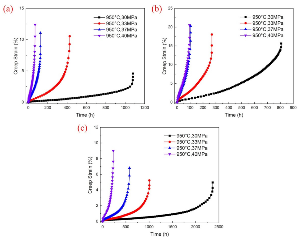
3.4. Creep Properties

Figure 10 exhibits the creep curves at various stress levels at 950 °C for the as-cast and aged alloys, along with the fresh-to-aged welded joint. The stress dependence of rupture time and the minimum creep strain rate is indicated in Figure 11. In general, similar creep deformation behaviors were obtained in these samples. They all exhibited well-defined primary, secondary, and tertiary creep stages under various creep conditions, while the rapid accumulation of strain in the tertiary creep stage prior to fracture was much larger than that in primary and secondary stages. In addition, the rupture time declined and the fracture strain increased with the growth of creep stress. Owing to the microstructural degradation after long-term thermal exposure, the rupture time of the aged alloy and the fresh-to-aged welded joint was obviously lower compared to the as-cast alloy at the same stress level. Nevertheless, the fracture strain of the fresh material was the lowest among these specimens, which may result from the softening of the aged microstructure during creep exposure. Furthermore, the fracture surfaces of the welded joint were located in the aged alloy, which originated from the coarsening carbides in the intra- and interdendritic regions after aging treatment. Stress dependence of rupture time and the minimum creep strain rate was linear in double-logarithmic plots, and the minimum creep strain rate values increased with the growth of stress levels. The minimum creep strain rates of the aged alloy and the fresh-to-aged welded joint were larger compared with the fresh alloy, which is attributed to the microstructural deterioration after long-term thermal exposure, as seen in Figure 11b.

4. Numerical Simulation

In our investigation, the empirically based, modified Kachanov–Rabotnov model considering the heterogeneity of creep damage was used to analyze the creep damage evolution of the fresh-to-aged welded joint and can be expressed in multi-axial form as follows [26]:
d ε i j c d t = 3 2 B σ e n 1 S i j 1 ρ + ρ 1 D n ,
d D d t = g A α σ 1 + ( 1 α ) σ e υ 1 + φ 1 D φ ,
D c r = 1 1 g 1 φ + 1 ,
where εij, Sij, σe, and σ1 are multi-axial strain components, deviatoric stress components, the von Mises equivalent stress, and the maximum principal stress, respectively. α represents the effect of the multi-axial stress state behavior of the material. D and Dcr are the damage variable and the critical damage, respectively. B, n, A, and υ are material constants, which can be determined according to the stress dependence of the minimum creep strain rate and rupture time, as shown in Figure 11. In addition, g and ρ are constants accounting for the inhomogeneity of the material damage and φ is the damage parameter, all of which can be obtained by the optimization algorithm based on the Newton iteration. The material constants in the creep constitutive equations for the as-cast and aged alloys are summarized in Table 4. The parameters of the weld metal are considered to be consistent with those of the as-cast alloy for simplicity in view of the similar chemical compositions. According to Equation (3), the value of critical damage for HP40Nb alloy can be calculated and is shown in Table 4. The critical damage of the fresh-to-aged welded joint corresponds to that of the aged alloy on account of the higher damage level in the aged alloy.
Considering the dimensional feature and loading profile of the fresh-to-aged welded joint, a 2D axisymmetric model composed of a weld metal and a base metal (as-cast tube and aged tube) was used, as shown in Figure 12. The length and thickness of the fresh-to-aged welded joint were 50 and 13 mm, respectively. The as-cast tube and the aged tube were located in the upper and lower parts, respectively. The element type was CAX4. The number of nodes and elements was 4132 and 4011, respectively. The boundary conditions of the top and bottom sides were both Y = 0. The applied internal pressure was 3.5 MPa. User subroutines programmed with FORTRAN for the finite element ABAQUS code were used to investigate the stress distribution and damage evolution.
Figure 13 shows the Mises stress distribution of the fresh-to-aged welded joint during creep exposure. The peak Mises stress was situated on the inner surface of the welded joint, and the stress descended toward the outer surface before creep. Stress redistribution occurred during the creep process. The value of the peak Mises stress reduced to 14.98 MPa, and the position of the peak Mises stress shifted to the interface of the weld metal and the aged tube when the creep time increased to 1 × 10⁴ h. In addition, the Mises stress in the aged tube was lower compared to that in the as-cast tube. With further exposure, the peak Mises stress increased to 15.27 MPa and then remained constant. The Mises stress evolution of the fresh-to-aged welded joint turned insignificant after creep for 1 × 10⁵ h. The contour of the damage distribution for the fresh-to-aged welded joint is also exhibited in Figure 14. The damage value rose continuously with service exposure, and the location of peak damage changed gradually. The maximum damage was located on the inner surface of the aged tube at 1 × 10⁴ h, with the value of 1.86%. With further exposure, the position of the peak damage shifted to the region adjacent to the outer wall at 5 × 10⁴ h and the damage value increased to 9.179%. The peak damage reached 34.01% in the outer wall of the aged tube when the creep time increased to 1.5 × 10⁵ h, while the highest damage was about 20.82% in the weld metal and the as-cast tube. In other words, the peak damage lies in the aged reformer tube during the creep process, which suggests that the microstructural degradation results in more serious damage evolution in the aged tube. However, the welding residual stress and the complex microstructures of the fresh-to-aged welded joint were not considered in numerical simulation. Meanwhile, void nucleation and growth occur in sequence for the service reformer tube, while the voids were absent in the aged alloy. Actually, the chemical composition of the filler metal differs from that of the fresh alloy. As mentioned above, the HAZ is not significant and the boundary between base metal and weld metal is mainly composed of a fusion zone. The parameters of the filler metal and the fusion zone were both unavailable. For simplicity, the material parameters of the filler metal corresponded to the as-cast alloy and the parameters in the fusion zone were ignored in this study. Therefore, the prediction of damage evolution for the fresh-to-aged welded joint is comparatively conservative in the finite simulation, and the stress and damage distribution are not continuous at the conjunction of the weld metal and the aged tube (BM).

5. Conclusions

The weldability of fresh-to-aged reformer furnace tubes was investigated based on microstructural characterization and tensile tests. Damage evaluations of a fresh-to-aged welded joint were carried out using the modified Kachanov–Rabotnov model. The main conclusions are as follows:
(1) The interdendritic M7C3 carbide transformed into M23C6 carbide after aging treatment at 990 °C, and interdendritic M23C6 carbide and NbC coarsened gradually with continuous exposure. Moreover, the number of precipitated M23C6 secondary carbides reduced by degrees.
(2) Micro-defects were absent in the fresh-to-aged welded joint, and the tensile strength of the welded joint was greater compared with the as-cast and aged alloys, which demonstrates the weldability of fresh-to-aged reformer tubes. Nevertheless, the heating and cooling rates in the welding process are supposed to be slowed down to inhibit cold-cracking.
(3) The creep rupture time of the as-cast alloy was greater compared with the aged alloy and the fresh-to-aged welded joint, while the fracture strain and the minimum creep strain rate were the lowest among the creep specimens.
(4) The stress and damage distributions in the fresh-to-aged welded joint changed continuously during the creep process. The highest Mises stress shifted to the interface of the weld metal and the aged tube with further exposure, while the predicted peak damage of the welded joint reached 34.01% in the outer wall of the aged tube at 1.5 × 10⁵ h.

Author Contributions

Software, C.F. and T.Z.; formal analysis, C.F. and Y.Z.; investigation, C.F. and B.S.; resources, B.S.; data curation, C.F. and Y.Z.; writing—original draft preparation, C.F.; writing—review and editing, C.F., X.G. and J.G.; supervision, J.G. and X.W.; funding acquisition, X.W. All authors discussed the results and contributed greatly to the final manuscript. All authors have read and agreed to the published version of the manuscript.

Funding

The authors gratefully acknowledge the support provided by the National Key Research & Development (R&D) Program of China (no. 2018YFC0808800) and the National Natural Science Foundation of China (nos. 51805274 and 51905261).

Institutional Review Board Statement

Not applicable.

Informed Consent Statement

Not applicable.

Data Availability Statement

Not applicable.

Conflicts of Interest

The authors declare no conflict of interest.

References

  1. Bonaccorsi, L.; Guglielmino, E.; Pino, R.; Servetto, C.; Sili, A. Damage analysis in Fe-Cr-Ni centrifugally cast alloy tubes for reforming furnaces. Eng. Fail. Anal. 2014, 36, 65–74. [Google Scholar] [CrossRef]
  2. Bahrami, A.; Taheri, P. Creep failure of reformer tubes in a petrochemical plant. Metals 2019, 9, 1026. [Google Scholar] [CrossRef] [Green Version]
  3. Abbasi, M.; Park, I.; Ro, Y.; Ji, Y.; Ayer, R.; Shim, J.-H. G-phase formation in twenty-years aged heat-resistant cast austenitic steel reformer tube. Mater. Charact. 2019, 148, 297–306. [Google Scholar] [CrossRef]
  4. API. Calculation of Heater Tube Thickness in Petroleum Refineries: API Recommended Practice 530, 3rd ed.; API: Washington, DC, USA, 1988. [Google Scholar]
  5. Alvino, A.; Lega, D.; Giacobbe, F.; Mazzocchi, V.; Rinaldi, A. Damage characterization in two reformer heater tubes after nearly 10 years of service at different operative and maintenance conditions. Eng. Fail. Anal. 2010, 17, 1526–1541. [Google Scholar] [CrossRef]
  6. Haidemenopoulos, G.N.; Polychronopoulou, K.; Zervaki, A.D.; Kamoutsi, H.; Alkhoori, S.I.; Jaffar, S.; Cho, P.; Mavros, H. Aging Phenomena during In-service creep exposure of heat-resistant steels. Metals 2019, 9, 800. [Google Scholar] [CrossRef] [Green Version]
  7. Gong, J.M.; Tu, S.T.; Yoon, K.B. Damage assessment and maintenance strategy of hydrogen reformer furnace tubes. Eng. Fail. Anal. 1999, 6, 143–153. [Google Scholar] [CrossRef]
  8. Kondrat’ev, S.Y.; Anastasiadi, G.P.; Ptashnik, A.V.; Petrov, S.N. Kinetics of the high-temperature oxidation of heat-resistant statically and centrifugally cast HP40NbTi alloys. Oxid. Met. 2019, 91, 33–53. [Google Scholar] [CrossRef]
  9. Silveiraa, R.; Arenas, M.P.; Pacheco, C.J.; Rocha, A.C.; Eckstein, C.B.; Bruno, A.C.; Pereira, G.R.; Almeida, L.H. Characterization of the oxide scale formed on external surface of HP reformer tubes. J. Mater. Res. Technol. 2018, 7, 578–583. [Google Scholar] [CrossRef]
  10. Tancret, F.; Laigo, J.; Christien, F.; Gall, R.L.; Furtado, J. Phase transformations in Fe-Ni-Cr heat-resistant alloys for reformer tube applications. Mater. Sci. Technol. 2019, 34, 1333–1343. [Google Scholar] [CrossRef]
  11. Almeida, L.H.D.; Ribeiro, A.F.; May, I.L. Microstructural characterization of modified 25Cr-35Ni centrifugally cast steel furnace tubes. Mater. Charact. 2003, 49, 219–229. [Google Scholar] [CrossRef]
  12. Andrade, A.; Bolfarini, C.; Ferreira, L.; Vilar, A.; Filho, C.S.; Bonazzi, L. Influence of niobium addition on the high temperature mechanical properties of a centrifugally cast HP alloy. Mater. Sci. Eng. A. 2015, 628, 176–180. [Google Scholar] [CrossRef]
  13. Attarian, M.; Taheri, A.K.; Jalilvand, S.; Habibi, A. Microstructural and failure analysis of welded primary reformer furnace tube made of HP-Nb micro alloyed heat resistant steel. Eng. Fail. Anal. 2016, 68, 32–51. [Google Scholar] [CrossRef]
  14. Abbasi, M.; Park, I.; Ro, Y.; Nam, J.; Ji, Y.; Kim, J.; Ayer, R. Microstructural evaluation of welded fresh-to-aged reformer tubes used in hydrogen production plants. Eng. Fail. Anal. 2018, 92, 368–377. [Google Scholar] [CrossRef]
  15. Fuyang, C.-M.; Zhu, R.; Zhang, P.-P.; Guo, X.-F.; Li, H.; Geng, L.-Y.; Gong, J.-M. Feasibility assessment of local repairment for reformer furnace tubes in service exposure. Int. J. Pres. Ves. Pip. 2020, 179, 104032. [Google Scholar] [CrossRef]
  16. Fuyang, C.-M.; Chen, J.-Y.; Shao, B.; Zhou, Y.; Gong, J.-M.; Guo, X.-F.; Jiang, Y. Effect of microstructural evolution in thermal exposure on mechanical properties of HP40Nb alloy. Int. J. Pres. Ves. Pip. 2021, 191, 104391. [Google Scholar] [CrossRef]
  17. Mostafaei, M.; Shamanian, M.; Purmohamad, H.; Amini, M.; Saatchi, A. Microstructural degradation of two cast heat resistant reformer tubes after long term service exposure. Eng. Fail. Anal. 2011, 18, 164–171. [Google Scholar] [CrossRef]
  18. Tomków, J.; Janeczek, A. Underwater in situ local heat treatment by additional stitches for improving the weldability of steel. Appl. Sci. 2020, 10, 1823. [Google Scholar] [CrossRef] [Green Version]
  19. Tomków, J.; Janeczek, A.; Rogalski, G.; Wolski, A. Underwater local cavity welding of S460N steel. Materials 2020, 13, 5535. [Google Scholar] [CrossRef] [PubMed]
  20. Mostafaei, M.; Shamanian, M.; Purmohamad, H.; Amini, M. Increasing weldability of service-aged reformer tubes by partial solution annealing. J. Mater. Eng. Perform. 2016, 25, 1291–1303. [Google Scholar] [CrossRef]
  21. Bhaumik, S.; Rangaraju, R.; Parameswara, M.; Bhaskaran, T.; Venkataswamy, M.; Raghuram, A.; Krishnan, R. Failure of reformer tube of an ammonia plant. Eng. Fail. Anal. 2002, 9, 553–561. [Google Scholar] [CrossRef]
  22. Branza, T.; Deschaux-Beaume, F.; Sierra, G.; Lours, P. Study and prevention of cracking during weld-repair of heat-resistant cast steels. J. Mater. Process. Technol. 2009, 209, 536–547. [Google Scholar] [CrossRef] [Green Version]
  23. Kachanov, L.M. Rupture time under creep condition. Izvestia Akademi Nauk SSSR Otd. Tekhn Nauk. 1958, 8, 26–31. [Google Scholar]
  24. Rabotnov, Y.N. Creep Problems in Structural Members; Elsevier (North Holland Publishing, Co.): Amsterdam, The Netherlands, 1969. [Google Scholar]
  25. Hayhurst, D. Creep rupture under multi-axial states of stress. J. Mech. Phys. Solids. 1972, 20, 381–382. [Google Scholar] [CrossRef]
  26. Liu, Y. A Localized Creep Damage Theory and Its Application to Creep Crack Growth; Southwestern Jiaotong University: Chengdu, China, 1990. (In Chinese) [Google Scholar]
  27. Liu, Y.; Murakami, S. Damage localization of conventional creep damage models and proposition of a new model for creep damage analysis. JSME Int. J. 1998, 41, 57–65. [Google Scholar] [CrossRef] [Green Version]
  28. Othman, A.M.; Hayhurst, D.R.; Dyson, B.F. Skeletal point stresses in circumferentially notched tension bars undergoing tertiary creep modeled with physically based constitutive equations. Proc. R. Soc. Lond. A 1993, 441, 343–358. [Google Scholar]
  29. Kowalewski, Z.L.; Hayhurst, D.R.; Dyson, B.F. Mechanisms-based creep constitutive equations for an aluminium alloy. J. Strain. Anal. Eng. Des. 1994, 29, 309–316. [Google Scholar] [CrossRef]
  30. Perrin, I.J.; Hayhurst, D.R. Creep constitutive equations for a 0.5Cr-0.5Mo-0.25V ferritic steel in the temperature range 600 °C to 675 °C. J. Strain Anal. Eng Des. 1996, 31, 299–314. [Google Scholar] [CrossRef]
  31. Dyson, B. Use of CDM in materials modeling and component creep life prediction. J. Pres. Ves. Technol. ASME. 2000, 122, 281–296. [Google Scholar] [CrossRef]
  32. Larson, F.R.; Miller, J. A time-temperature relationship for rupture and creep stress. Trans. ASME 1952, 74, 765–771. [Google Scholar]
  33. Burke, K.E. Chemical extraction of refractory inclusions from iron- and nickel-base alloys. Metallography 1975, 8, 473–488. [Google Scholar] [CrossRef]
  34. Shi, S.; Lippold, J.C. Microstructure evolution during service exposure of two cast, heat-resisting stainless steels—HP-Nb modified and 20-32Nb. Mater. Charact. 2008, 59, 1029–1040. [Google Scholar] [CrossRef]
  35. Dessolier, T.; McAuliffe, T.; Hamer, W.J.; Hermse, C.G.M.; Britton, T.B. Effect of high temperature service on the complex through-wall microstructure of centrifugally cast HP40 reformer tube. Mater. Charact. 2021, 111070. [Google Scholar] [CrossRef]
  36. Chen, Q.Z.; Thomas, C.W.; Knowles, D.M. Characterisation of 20Cr32Ni1Nb alloys in as-cast and ex-service conditions by SEM, TEM and EDX. Mater. Sci. Eng. A 2004, 374, 398–408. [Google Scholar] [CrossRef]
  37. Soares, G.D.D.A.; Almeida, L.H.D.; Silveira, T.L.D.; May, I.L. Niobium additions in HP heat-resistant cast stainless steels. Mater. Charact. 1992, 29, 387–396. [Google Scholar] [CrossRef]
  38. Guo, X.; Jia, X.; Gong, J.; Geng, L.; Tang, J.; Jiang, Y.; Ni, Y.; Yang, X. Effect of long-term aging on microstructural stabilization and mechanical properties of 20Cr32Ni1Nb steel. Mater. Sci. Eng. A 2017, 690, 62–70. [Google Scholar] [CrossRef]
Figure 1. Configuration and dimensions of the specimen for constant-load creep tests (Units: mm).
Metals 11 00900 g001
Figure 2. Representative XRD patterns of extracted residues in as-cast HP40Nb alloy and the specimens after aging at 990 °C.
Metals 11 00900 g002
Figure 3. Typical optical microscopy images of (a) as-cast HP40Nb alloy and the specimens after aging at 990 °C for (b) 500, (c) 2000, and (d) 4000 h.
Metals 11 00900 g003
Figure 4. Typical back-scattered electron (BSE)–SEM images of (a) as-cast HP40Nb alloy and the samples after aging at 990 °C for (b) 500, (c) 2000, and (d) 4000 h.
Metals 11 00900 g004
Figure 5. Precipitations of as-cast HP40Nb alloy detected using SEM elemental mapping: (a) SEM image, (b) Cr, (c) Fe, (d) Ni, (e) Nb and (f) Si elements.
Metals 11 00900 g005
Figure 6. Precipitations in the sample after aging at 990 °C for 2000 h detected using SEM elemental mapping: (a) SEM image, (b) Cr, (c) Fe, (d) Ni, (e) Nb and (f) Si elements.
Metals 11 00900 g006
Figure 7. Optical microscopy images of the fresh-to-aged welded joint: (a) fresh alloy/weld metal and (b) aged alloy/weld metal.
Metals 11 00900 g007
Figure 8. Optical microscopy images of melted carbides in the fusion zone for (a) as-cast alloy and (b) aged alloy.
Metals 11 00900 g008
Figure 9. Typical stress–strain plots of the as-cast alloy, aged alloy, and fresh-to-aged welded joint at (a) room temperature and (b) elevated temperature (950 °C).
Metals 11 00900 g009
Figure 10. Standard creep time–strain curves of (a) as-cast alloy, (b) aged alloy, and (c) fresh-to-aged welded joint at 950 °C.
Metals 11 00900 g010
Figure 11. Stress dependence of (a) rupture time and (b) minimum creep strain rate at 950 °C for the as-cast alloy, aged alloy, and fresh-to-aged welded joint.
Metals 11 00900 g011
Figure 12. FE model and element division of the welded joint.
Metals 11 00900 g012
Figure 13. Mises stress distribution of the fresh-to-aged welded joint at (a) 0, (b) 1 × 10⁴, (c) 1 × 10⁵, and (d) 1.5 × 10⁵ h.
Metals 11 00900 g013
Figure 14. Damage distribution of the fresh-to-aged welded joint at (a) 1 × 10⁴, (b) 5 × 10⁴, (c) 1 × 10⁵, and (d) 1.5 × 10⁵ h.
Metals 11 00900 g014
Table 1. Chemical composition of base metal and filler metal (wt %).
MaterialCNiCrNbSiMnPSFe
HP40Nb
TIG 35CW
0.45
0.41
34.13
34.95
25.47
25.12
0.70
1.28
1.35
1.49
1.03
1.30
0.029
0.025
0.008
0.006
Bal.
Bal.
Table 2. Aging time versus operating time of HP40Nb alloy.
Temperature/°C900910920930940950990
Time/h3 × 104
1.2 × 10⁵
2.5 × 10⁵
1.5 × 10⁴
8 × 10⁴
1.5 × 10⁵
1 × 10⁴
5 × 10⁴
1 × 10⁵
6000
3 × 10⁴
6 × 10⁴
4000
2 × 10⁴
4 × 10⁴
3000
1.2 × 10⁴
2.4 × 10⁴
500
2000
4000
Table 3. Tensile properties of the as-cast HP40Nb alloy, aged alloy, and fresh-to-aged welded joint.
Temperature (°C)ConditionYield Strength (MPa)Ultimate Tensile Strength (MPa)Elongation (%)
20As-cast alloy248.35500.4626.67
Aged alloy258.39490.694.17
Welded joint369.32496.972.50
950As-cast alloy87.12108.3436.55
Aged alloy68.44102.4243.37
Welded joint92.17119.2921.05
Table 4. Material constants in the damage constitutive equations for HP40Nb alloy at 950 °C.
MaterialBnAυgρφαDcr
As-cast alloy
Aged alloy
8.18 × 10⁻²⁰
1.75 × 10⁻²²
9.22
11.91
2.14 × 10⁻¹⁵
8.24 × 10⁻¹⁵
7.65
7.62
0.92
0.88
0.18
0.06
2.9
3.8
0.25
0.25
0.477
0.357
Publisher’s Note: MDPI stays neutral with regard to jurisdictional claims in published maps and institutional affiliations.

