Article

Effect of Cutting Parameters and Tool Geometry on the Performance Analysis of One-Shot Drilling Process of AA2024-T3

1
School of Engineering, Edith Cowan University, Joondalup 6027, Australia
2
School of Mechanical and Design Engineering, University of Portsmouth, Portsmouth PO1-3DJ, UK
3
Research Centre for Modelling and Simulation (RCMS), National University of Sciences and Technology (NUST), Sector H-12, Islamabad 44000, Pakistan
4
Department of Mechanical Engineering, CECOS University of Information Technology and Emerging Sciences, Peshawar 25000, Pakistan
5
Department of Mechanical Engineering, Faculty of Engineering, Karamanoglu Mehmetbey University, Karaman 70100, Turkey
6
Department of Automated Mechanical Engineering, South Ural State University, Lenin Prosp. 76, 454080 Chelyabinsk, Russia
*
Author to whom correspondence should be addressed.
Metals 2021, 11(6), 854; https://doi.org/10.3390/met11060854
Submission received: 16 April 2021 / Revised: 13 May 2021 / Accepted: 20 May 2021 / Published: 23 May 2021
(This article belongs to the Special Issue Optimization and Analysis of Metal Cutting Processes)

Abstract

:
Drilling is an important machining process in various manufacturing industries. High-quality holes are possible with the proper selection of tools and cutting parameters. This study investigates the effect of spindle speed, feed rate, and drill diameter on the generated thrust force, the formation of chips, post-machining tool condition, and hole quality. The hole surface defects and the top and bottom edge conditions were also investigated using scan electron microscopy. The drilling tests were carried out on AA2024-T3 alloy under a dry drilling environment using 6 and 10 mm uncoated carbide tools. Analysis of Variance was employed to further evaluate the influence of the input parameters on the analysed outputs. The results show that the thrust force was highly influenced by feed rate and drill size. The high spindle speed resulted in higher surface roughness, while the increase in the feed rate produced more burrs around the edges of the holes. Additionally, the burrs formed at the exit side of holes were larger than those formed at the entry side. The high drill size resulted in greater chip thickness and an increased built-up edge on the cutting tools.

1. Introduction

Aluminium alloys contribute to many manufacturing industries such as the aerospace and automotive industries, where strong, durable, and lightweight products are required [1]. Alloys of aluminium, particularly those from the 2000 series, are commonly used in modern aircrafts’ airframe structures. For instance, AA2024-T3 is installed in aircraft fuselage skins due to its high fatigue resistance [2]. Furthermore, in the aerospace industry, the drilling process is used to assemble different structures, and thus a large number of holes are required for installing rivets and bolts [3,4,5]. Poor hole quality can lead to part rejections in quality control. Hence, a higher degree of research is required to enhance the holes’ quality and minimise the incidence associated with the drilling operation [6,7].
Tool wear, chip formation, and hole quality are key parameters of the drilling process and are strongly influenced by spindle speed (n), feed rate (f), tool geometry, machine tool setup, and cutting conditions such as wet/dry or other environmental factors [8,9,10,11,12]. In contrast to wet machining, dry drilling is preferable to reduce the environmental impact of coolants and eliminate the costs of cutting fluids [13]. However, during the dry drilling process, there are more chances of forming a built-up edge (BUE), which can reduce the tool’s life and affect the hole quality [14]. Hence, the proper selection of drilling parameters is essential in combination with the use of suitable drilling tools to avoid deformation of the workpiece or breakage of the cutting tool [15]. Previous studies for improving the drilling operation and producing high-quality holes are given in Table 1.
For instance, Reddy et al. [16] reported that n was the most dominant factor that affected the hole diameter following the f during drilling of Al6061, Al6351, and Al7075. In comparison, the impact of point angle on hole diameter was the lowest. Kushnoore et al. [17] conducted drilling experiments on Al6061 and concluded that an increase in drill diameter, n, and f affected the thrust force, torque, and circularity error. Gunay et al. [18] have demonstrated that increasing f led to an increased thrust force while increasing drill point angle resulted in a lower thrust force. Moreover, a low f and high point angle were suggested for attaining minimum surface roughness in the drilling of Al7075. In another study by Sreenivasulu and Rao [19], it was revealed that during the drilling of Al7075, the most influential parameters on burr height, thrust force, surface roughness, and circularity were f, point angle, and clearance angles, as compared to n and drill diameter. Kyratsis et al. [20] concluded that tool diameter and f affected the thrust force and torque. In contrast, the impact of n on both the thrust force and torque was considerably smaller during Al7075 drilling. Balaji et al. [21] worked on the drilling of Ti-6Al-4V and concluded that high frictional stresses and heat generation increased with the increase in n and helix angle. While the surface roughness was more influenced by n and f; however, the helix angle did not contribute more to the surface roughness. It was further found that surface roughness was affected by the drill vibration. The reasons for the increase in the tool wear were the high n and f. Abdelhafeez et al. [22] conducted drilling experiments on Ti-6Al-4V, Al7010, and Al2024. The study found that the exit burr size was statistically more affected by f in all the materials, and no significant impact of cutting speed and f was found on the circularity error and diameter oversize. Furthermore, Pena et al. [23] developed a thresholding algorithm based on internal signals from spindle torque to detect non-desired burr formation during the drilling operations of Al7075-T6. The algorithm was successfully developed with an accuracy above 92% and was expected to be used as an effective quality control in drilling operations.
The above studies indicate that most of the previous work was conducted either on other metal alloys or when the cutting parameters were different. Moreover, some studies lack investigations into hole quality and other output parameters in combination with the thrust force or torque. Additionally, keeping in view the higher importance of the drilling process for high-quality holes, this work investigates the effect of tool geometry in terms of drill size, spindle speed, and feed rate in the one-shot dry drilling process of AA2024-T3 using the uncoated carbide tools. Therefore, the performance of the drilling process was evaluated in terms of thrust force, chip analysis, and tool conditions to assess the surface roughness and burrs formation. Furthermore, the hole surface defects were investigated using scan electron microscopy.

2. Materials and Methods

The drilling process was performed on a vertical manual milling machine using spindle speeds of 1000, 2000, and 3000 rpm and feed rates of 0.04, 0.08, and 0.14 mm/rev. All the experiments were conducted without the use of coolants because dry conditions are considered an eco-friendlier process [24,25]. The tools selected were uncoated carbide drill bits. Carbide twist drills are highly acknowledged for drilling aluminium alloys, especially AA2024-T3 [26], due to their enhanced hardness and toughness [27]. T3 is the temper designation for aluminium alloy, which means the alloy is solution treated, cold-worked, and naturally aged [1]. Table 2 shows the technical specifications for the drill bits used in this study.
All the drilling experiments were performed on AA2024-T3, which is the commonly used alloy in the aerospace industry [1,28]. The thickness of the workpiece material was 10 mm, and the dimensions were 200 × 150 mm2. A Kistler force dynamometer type 9257BA was used to measure force signals during the drilling operation. The dynamometer was fitted on the machine bed, and a support plate was mounted on its top for safety, which also acted as a fixture to avoid deflection/vibration during the drilling operation. The thrust force was measured using the Kistler’s dynamometer. The quality of the holes was evaluated using a digital microscope, and the tool condition was examined using the optical microscope. The average surface roughness (Ra) of the holes was measured three times at four different locations of the hole edges at 90° using the surface roughness tester TR200 (PCWI- precision instrumentation, Australia), and the average readings were considered for evaluation. The Ra values were taken as per the International Organization for Standardization (ISO) code: 4287. The hole surface quality was examined using scanning electron microscopy (SEM). The samples were cut in half and examined under SEM using a Hitachi SU5000 Chiyoda, Japan, scanning electron microscope. Finally, the percentage contribution that each input parameter had on the output parameters was evaluated using ANOVA (Analysis of Variance).

3. Results and Discussion

3.1. Thrust Force

Figure 1 shows the thrust force (Fz) generated signals of 6 mm and 10 mm drills for one of the drilled holes. The first region of the force signals shows the drill engagement where the tool penetrated the workpiece and Fz began processing. With the drill bit’s advancement, the Fz gradually increased then reached a steady state while the drill was in full contact with the workpiece. The Fz declined rapidly when approaching the bottom side of the workpiece and then reached zero when the drill bit completely exited the workpiece, indicating the end of the drilling process [29].
The average Fz measured during the dry drilling process using 6 mm and 10 mm drill size at different n and f selected in this study is given in Figure 2. The results showed that the 10 mm drills generated a higher Fz compared to that from the 6 mm drills due to the larger contact area between the drill and the workpiece. Figure 2 also illustrates that Fz increased as n and f increased; however, the ANOVA analysis in Table 3 indicated that f had the highest percentage contribution at 67.33%, followed by the drill diameter with a contribution of 29.53%, while the influence of n was insignificant (0.81%). The increase in Fz due to the increase in f might be associated with the increase in uncut chip thickness [30,31,32]. A confidence interval of 95% was used in the ANOVA; therefore, the influence of each process parameter on the responses was considered insignificant if their p-values were estimated at more than 0.05.

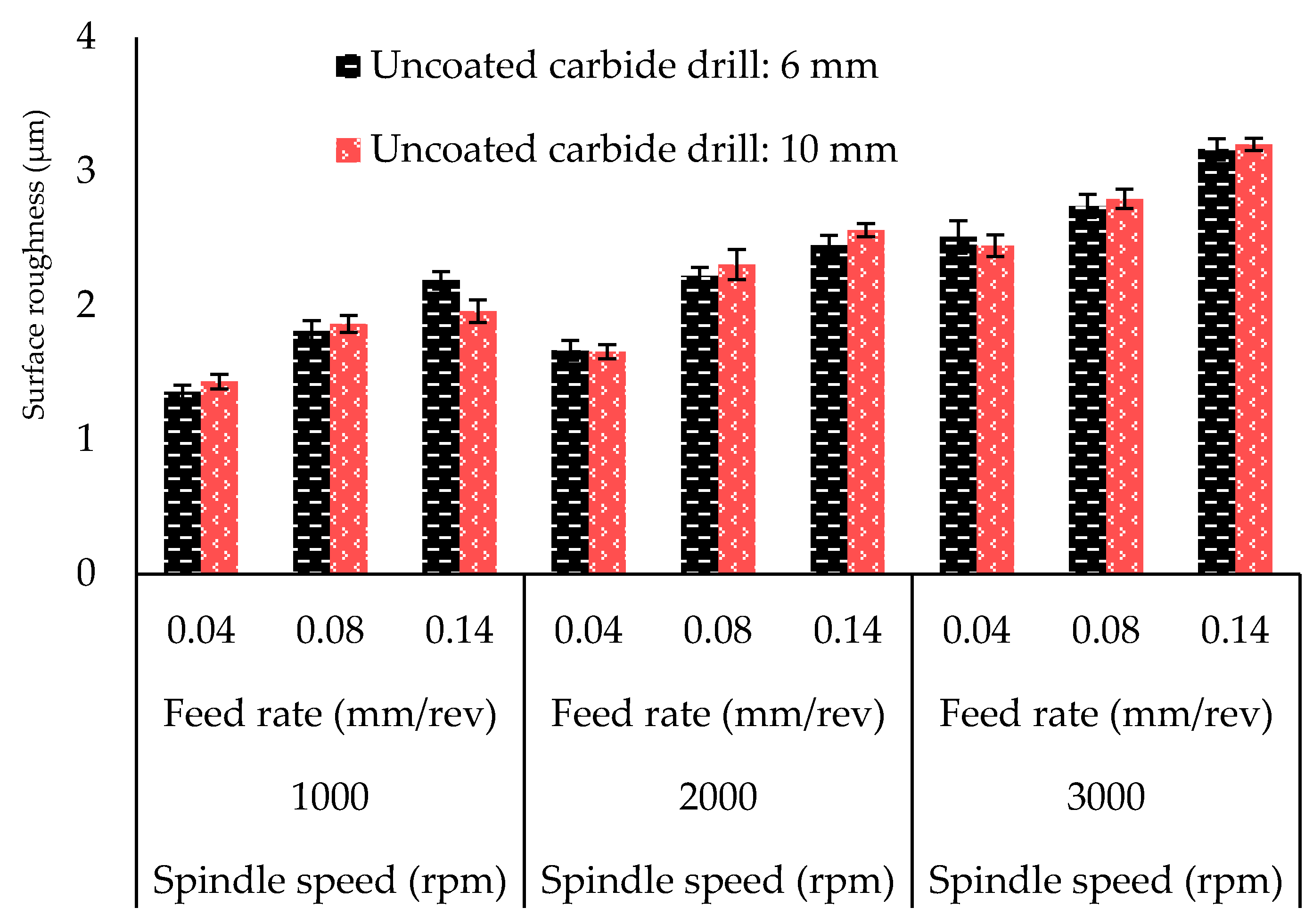
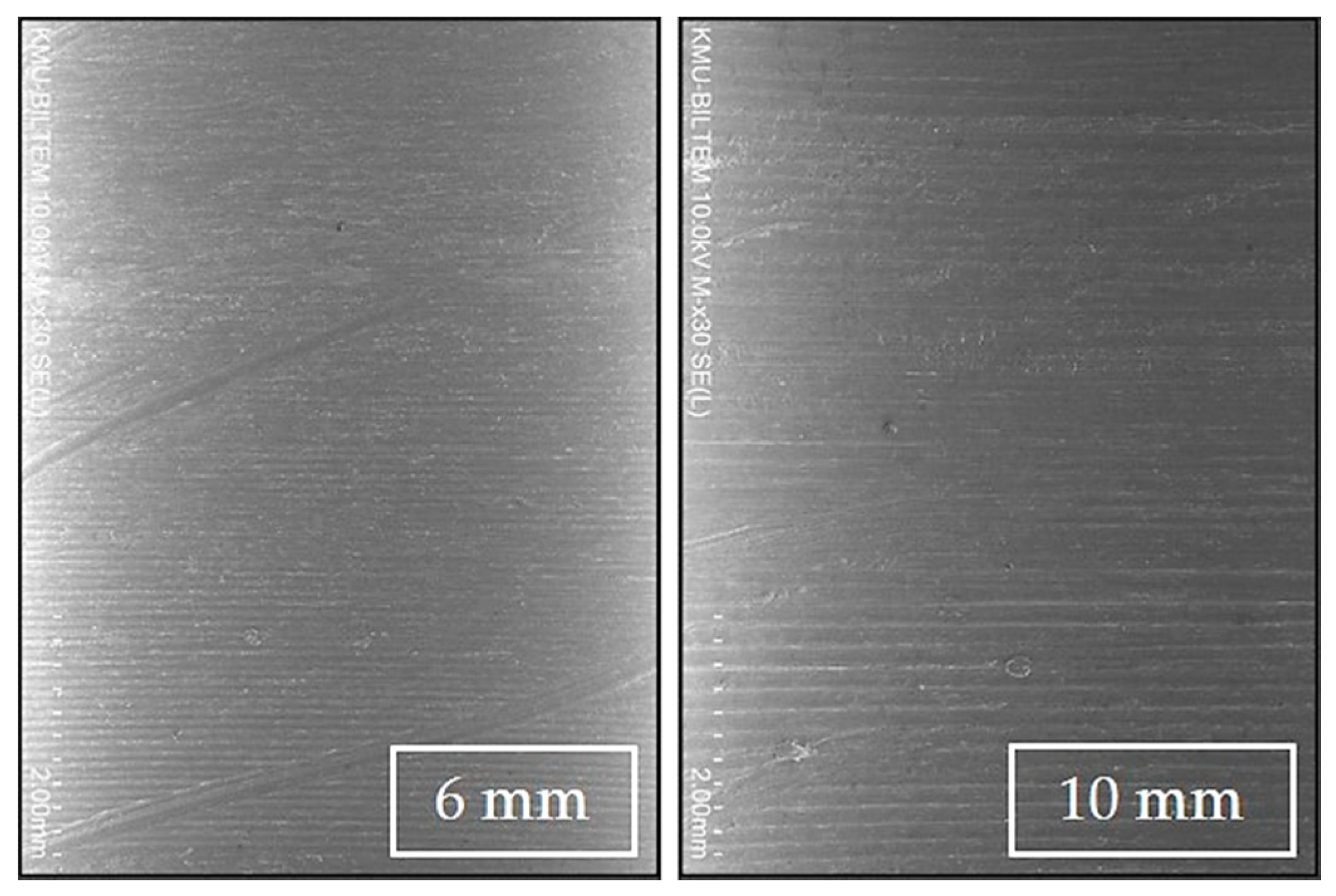
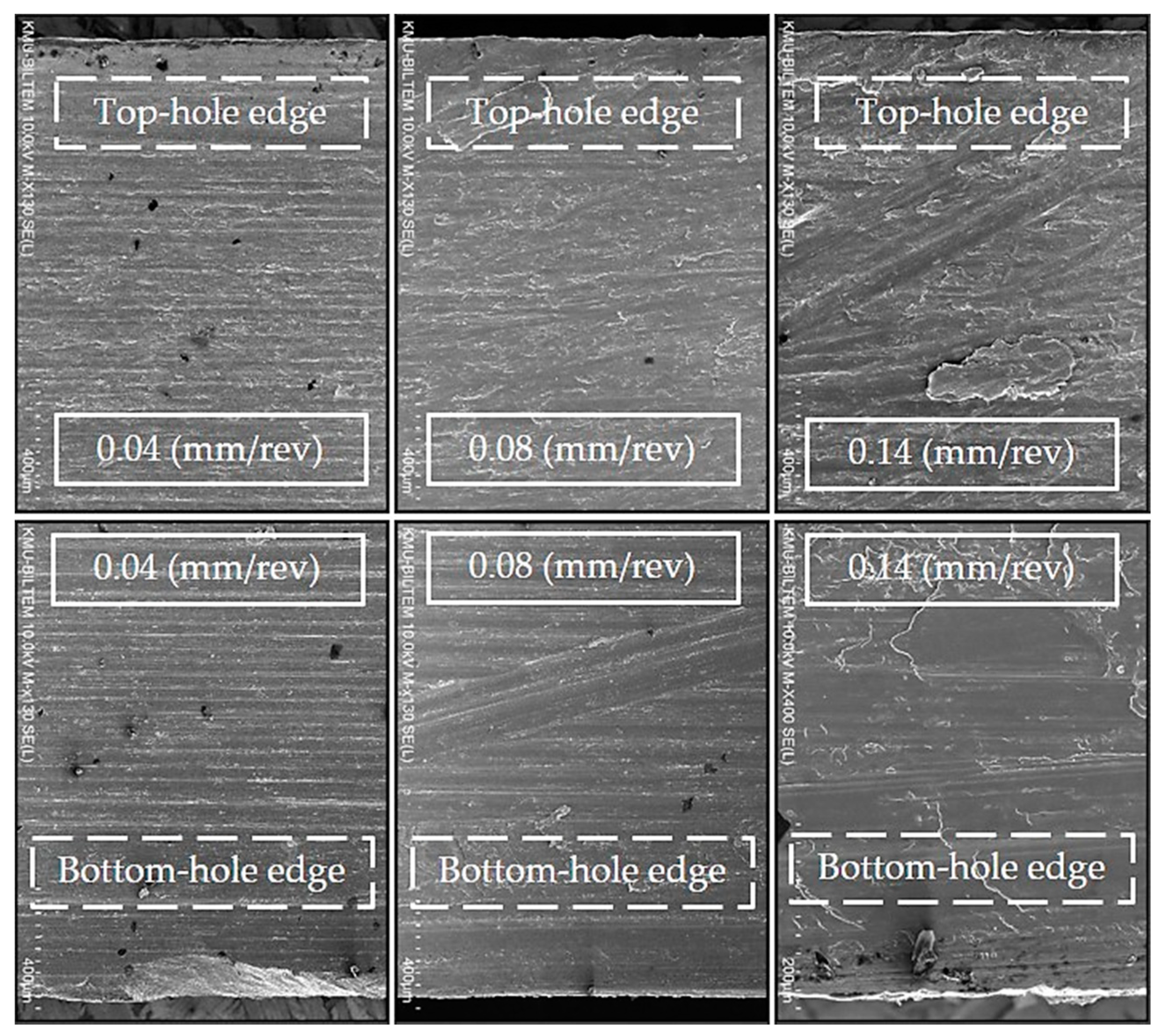
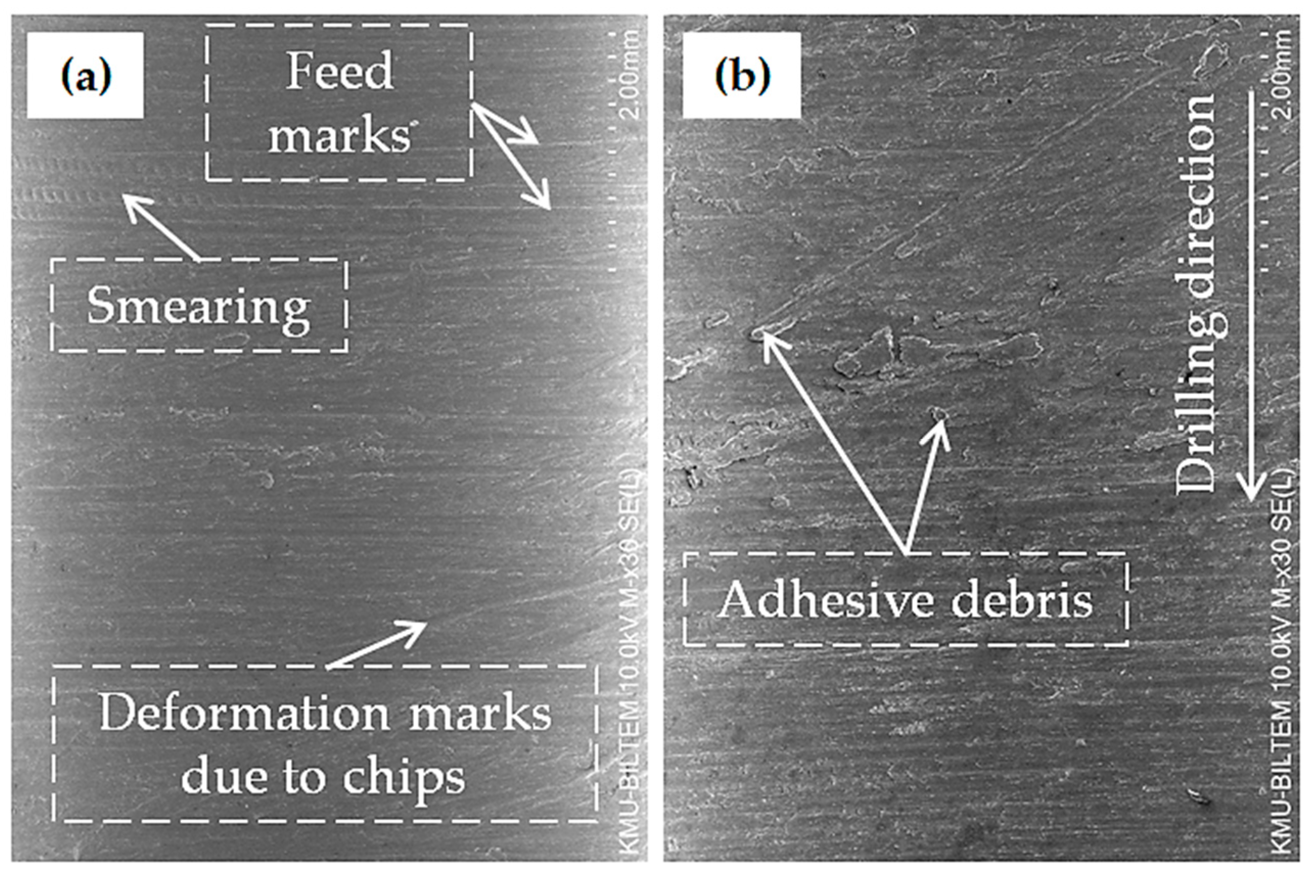
3.2. Surface Roughness, Burr Formation, and Hole Surface Damage Analysis

Figure 3 depicts the surface roughness (Ra) of holes drilled in AA2024-T3 alloy. The results show that increases in both n and f increased Ra, irrespective of the drill size. However, Ra of the holes drilled using the 10 mm drill bits were found to be almost similar to those obtained from drill bits with a 6 mm size, which is in agreement with the findings of Köklü [33]. The minor increase from the large-size drills was speculated to be due to covering a larger contact area, resulting in increased BUE formation, which in turn increased the Fz and Ra [34]. The high Ra due to the increase in n is attributed to the rise in cutting temperature, which increases the thermal softening of the material and hole deformation [15]. Moreover, the high f increased the thickness of the chips, which contributed to the higher values of Ra [30]. Table 4 from the ANOVA results shows that n had the highest percentage contribution at 65.29%, followed by f with an impact of 32.72% on Ra. The influence of D and other interactions were found insignificant as their p-values were more than 0.05.
Another essential characteristic of hole quality was the burrs at the entry and exit of holes. Therefore, in this study, burrs around the hole edges were also thoroughly analysed using a digital microscope. The microscopic inspection also revealed less formation of burrs at the entry than those formed at the exit side. Additionally, both n and f contributed to the formation of burrs around the hole edges; however, f was dominant over n in increasing the burrs due to the high insertion of the drill because of the unstable performance [35]. The reason for high burr formation due to the higher n was due to the high percentage of the elongation of the AA2024-T3 alloy [29]. Figure 4 also indicates that the drill diameter had a minor influence on burr size and height when drilling the AA2024-T3 alloy. However, it was challenging to evaluate burr formation using optical microscopy accurately; therefore, SEM images were used to further investigate the burr formation.
Figure 5 shows the borehole for 6 and 10 mm holes drilled using the same cutting parameters. The SEM graphs reveal that the hole edge quality at the entrance was better than at the exit, regardless of the drill size. Moreover, it was also found that the hole edge quality at the entrance was better in holes drilled using 6 mm drills than those drilled using the 10 mm drills. This was also observed in the remaining drilled holes using different cutting parameters. The larger contact area between the cutting tool and workpiece at the start of the drilling process means that larger thrust force is required before the cutting tool is in full contact with the workpiece, leading to increased deformations and damage to the hole entry.
Similarly, the hole edge quality at the exit was better in holes drilled using 10 mm drills, as can be seen from Figure 5. It is speculated that the larger cross-sectional area of the 10 mm drills provided more stability and rigidity while drilling throughout the hole, which gave better cutting quality while the tool was exiting the workpiece. This claim can be supported by the fact that the surface deformations and damage observed on the boreholes drilled using 6 mm drills were somewhat more visible than those drilled using the 10 mm drills. Another observation supporting this claim is that aggressive helical feed marks were found on the inner surfaces of some of the holes drilled using the 6 mm drills, as shown in Figure 6. This would imply that the chip collision with the inner walls of the holes was more aggressive when using the 6 mm drills, which could be, as stated earlier, due to less drill stability.
Figure 7 shows the surface condition of holes drilled using 6 mm drills at different feed rates. It was observed that increasing f tended to reduce the hole surface quality. This is mainly attributed to the increased chip thickness with the increase in f. For example, when drilling at an f of 0.14 mm/rev, there are more clear signs of smearing and plastic flow due to severe plastic deformation on the upper and lower sides of the hole as well as throughout its thickness. This was also observed in holes drilled using the 10 mm drills and therefore is purely related to the increase in f.
Figure 8 shows the borehole condition for holes drilled using 10 mm drills at a different n and a constant f of 0.14 mm/rev. The results show that the edge quality at the hole entry seems to worsen with the increase in n, while the hole edge quality at the exit seemed to be unaffected. The results also showed that increasing n beyond 2000 rpm increased the severity of deformations due to plastic flow around the hole surface. This could be attributed to the increase in the cutting temperatures and ductility with the increase in n, which softens the material and induces more thermal stresses. It is also well known that the AA2024-T3 alloy possesses a relatively high percentage of elongation, which can affect the burr formation at the hole entry and exit sides [29]. For clarification, Figure 9 reveals the defects in the hole walls of AA2024-T3 from 6 mm and 10 mm drill bits.

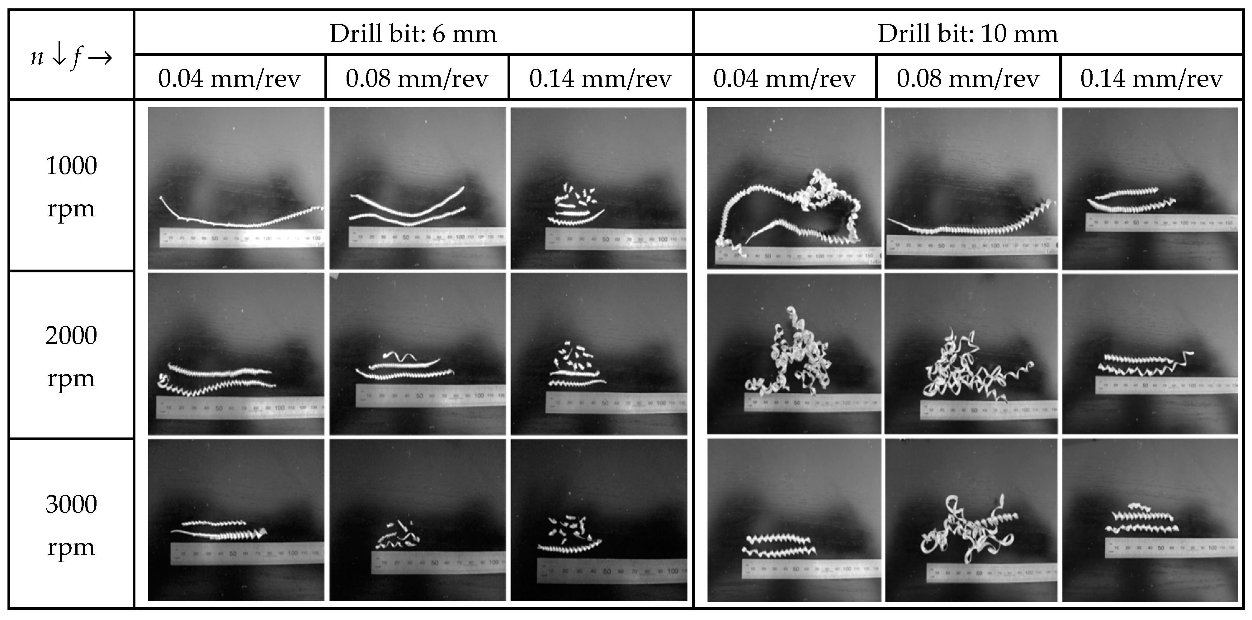
3.3. Chip Analysis and Tool Condition

Chip formation and its breaking mechanism signify the smooth drilling process [36]. Accordingly, the long and continuous chips can easily become tangled around the drill bit flutes and require manual removal, affecting the production [37]. Furthermore, the undesirable chips increase the formation of built-up edge (BUE), which in return would reduce the quality of holes [38]. Commonly, the reason behind the formation of BUE is the higher value of the coefficient of friction at the tool–chip interface [39]. Figure 10 shows the chips produced during dry drilling of AA2024-T3 using 6 and 10 mm uncoated carbide drills. The chip analysis showed that 10 mm uncoated carbide drill bits had thickened chips compared to the drill size of 6 mm because of the large cross-sectional area covered by its larger size [40]. Figure 10 also shows that, with the increase in both n and f, the length of the chip became shorter, while the thickness of the chip increased with the increase in f and decreased with the increase in n, irrespective of the drill size.
In the machining process, chips can adhere to the cutting tool to form BUE, resulting in deterioration of the cutting tool [41]. Additionally, according to Rodríguez et al. [24], during dry drilling operations there are chances of both high friction phenomena and chemical diffusion, which cause adhesion, burn marks, and flank wear. Therefore, the higher formation of BUE in drilling affects the hole quality. Depending upon the materials of the cutting tools and different geometries, BUE formation varies under the same cutting conditions. Figure 11 shows the condition of 6 mm and 10 mm drill bits during the drilling process of AA2024-T3, which indicated a BUE on both the tools. The microscopic inspection showed a higher BUE on the 10 mm drill bit compared to the drill size of 6 mm. The greater BUE on the 10 mm drill bit was due to larger chip formation, increased cutting forces, and the contact area between the cutting tool and the workpiece material. In contrast, small drill size led to easy chip evacuation and chip breakage due to the smaller chips.

4. Conclusions

This study investigated the effect of tool geometry and cutting conditions, such as spindle speed and feed rate, for the improvement of holes drilled in AA2024-T3. The following conclusions could be made from the investigations:
  • The thrust force was affected more with the increase in feed rate, while the impact of spindle speed on thrust force was found insignificant. Therefore, the percentage contributions of feed rate, drill size, and spindle speed on thrust force were 67.33%, 29.53%, and 0.81%, respectively.
  • The surface roughness increased with the increase in spindle speed and feed rate. The spindle speed had an impact of 65.29%, following the feed rate which had a percentage contribution of 32.72%, while the drill size had insignificant influence with a contribution of only 0.01%.
  • Both spindle speed and feed rate were influential on burrs formation; however, more burrs were formed with an increased feed rate. Furthermore, it was revealed that entry holes had fewer burrs than holes formed at the exit side.
  • The 10 mm size tool covered a large cutting area and produced chips with high thickness, thus generating high thrust force compared to the 6 mm size tool. The high chip thickness resulted in high built-up edges on the drill bits because the small drill size enabled easy chip evacuation and breaking due to the short chip size. The large built-up edge should be avoided for high-quality holes.
  • Both the drill sizes resulted in feed marks, chip debris, deformation due to chip adhesion, and smearing on the hole walls of AA2024-T3.
  • The study could be further extended to assess other important hole metrics such as deviation of the hole from nominal size, circularity, cylindricity, and perpendicularity. Moreover, drill bits with coatings and other geometric parameters should be used for further improvement of the holes.

Author Contributions

Conceptualization, M.A. and M.T.-R.; methodology, M.A. and K.G.; validation, M.A., K.G., M.T.-R. and D.Y.P.; investigation, M.A., and U.K.; writing—original draft preparation, M.A., M.I.H., M.I. and I.U.D.; writing—review and editing, K.G., I.U.D., M.I., U.K., D.Y.P. and M.I.H. All authors have read and agreed to the published version of the manuscript.

Funding

This research received no external funding.

Institutional Review Board Statement

Not applicable.

Informed Consent Statement

Not applicable.

Data Availability Statement

The data presented in this study are available on request.

Conflicts of Interest

The authors declare no conflict of interest.

Nomenclature

ANOVAAnalysis of Variance
BUEBuilt-up edge
SEMScan electron microscope
DDrill diameter
fFeed rate
nSpindle speed
RaSurface roughness
FzThrust force
VcCutting speed

References

  1. Aamir, M.; Giasin, K.; Tolouei-Rad, M.; Vafadar, A. A review: Drilling performance and hole quality of aluminium alloys for aerospace applications. J. Mater. Res. Technol. 2020, 9, 12484–12500. [Google Scholar] [CrossRef]
  2. Dursun, T.; Soutis, C. Recent developments in advanced aircraft aluminium alloys. Mater. Des. 2014, 56, 862–871. [Google Scholar] [CrossRef]
  3. Aamir, M.; Tolouei-Rad, M.; Giasin, K.; Nosrati, A. Recent advances in drilling of carbon fiber–reinforced polymers for aerospace applications: A review. Int. J. Adv. Manuf. Technol. 2019, 105, 2289–2308. [Google Scholar] [CrossRef]
  4. Tolouei-Rad, M.; Aamir, M. Analysis of the Performance of Drilling Operations for Improving Productivity. In Drilling; Tolouei-Rad, M., Ed.; IntechOpen: London, UK, 2021; Available online: https://www.intechopen.com/online-first/analysis-of-the-performance-of-drilling-operations-for-improving-productivity (accessed on 16 April 2021).
  5. Olvera, D.; de Lacalle, L.N.L.; Urbikain, G.; Lamikiz, A.; Rodal, P.; Zamakona, I. Hole making using ball helical milling on titanium alloys. Mach. Sci. Technol. 2012, 16, 173–188. [Google Scholar] [CrossRef]
  6. Al-Tameemi, H.A.; Al-Dulaimi, T.; Awe, M.O.; Sharma, S.; Pimenov, D.Y.; Koklu, U.; Giasin, K. Evaluation of Cutting-Tool Coating on the Surface Roughness and Hole Dimensional Tolerances during Drilling of Al6061-T651 Alloy. Materials 2021, 14, 1783. [Google Scholar] [CrossRef] [PubMed]
  7. Aamir, M.; Tolouei-Rad, M.; Giasin, K.; Vafadar, A.; Koklu, U.; Keeble, W. Evaluation of the Surface Defects and Dimensional Tolerances in Multi-Hole Drilling of AA5083, AA6061, and AA2024. Appl. Sci. 2021, 11, 4285. [Google Scholar] [CrossRef]
  8. Zhao, H. Predictive Models for Forces, Power and Hole Oversize in Drilling Operations. Doctoral Dissertation, The University of Melbourne, Victoria, Australia, 1994. [Google Scholar]
  9. Aamir, M.; Tu, S.; Tolouei-Rad, M.; Giasin, K.; Vafadar, A. Optimization and modeling of process parameters in multi-hole simultaneous drilling using taguchi method and fuzzy logic approach. Materials 2020, 13, 680. [Google Scholar] [CrossRef] [PubMed] [Green Version]
  10. Aamir, M.; Tu, S.; Giasin, K.; Tolouei-Rad, M. Multi-hole simultaneous drilling of aluminium alloy: A preliminary study and evaluation against one-shot drilling process. J. Mater. Res. Technol. 2020, 9, 3994–4006. [Google Scholar] [CrossRef]
  11. Aamir, M.; Tolouei-Rad, M.; Giasin, K.; Vafadar, A. Machinability of Al2024, Al6061, and Al5083 alloys using multi-hole simultaneous drilling approach. J. Mater. Res. Technol. 2020, 9, 10991–11002. [Google Scholar] [CrossRef]
  12. Aamir, M.; Tolouei-Rad, M.; Vafadar, A.; Raja, M.N.A.; Giasin, K. Performance Analysis of Multi-Spindle Drilling of Al2024 with TiN and TiCN Coated Drills Using Experimental and Artificial Neural Networks Technique. Appl. Sci. 2020, 10, 8633. [Google Scholar] [CrossRef]
  13. Sarikaya, M.; Gupta, M.K.; Tomaz, I.; Danish, M.; Mia, M.; Rubaiee, S.; Jamil, M.; Pimenov, D.Y.; Khanna, N. Cooling techniques to improve the machinability and sustainability of light-weight alloys: A state-of-the-art review. J. Manuf. Process. 2021, 62, 179–201. [Google Scholar] [CrossRef]
  14. Bhowmick, S.; Alpas, A.T. Minimum quantity lubrication drilling of aluminium–silicon alloys in water using diamond-like carbon coated drills. Int. J. Mach. Tools Manuf. 2008, 48, 1429–1443. [Google Scholar] [CrossRef]
  15. Osman, M.; Tamin, N.; Ahmad, M.; Rahman, M.A.; Wahid, M.; Maidin, N.; Bakar, M.A.; Azahar, A. Effect of cutting parameters on surface roughness in dry drilling of AISI D2 tool steel by using Taguchi method. J. Adv. Manuf. Technol. 2018, 12, 535–546. [Google Scholar]
  16. Reddy, A.S.; Kumar, G.V.; Thirupathaiah, C. Influence of the cutting parameters on the hole diameter accuracy and the thrust force in drilling of aluminium alloys. Int. J. Innov. Res. Sci. Eng. Technol. 2013, 2, 6442–6450. [Google Scholar]
  17. Kushnoore, S.; Noel, D.; Kamitkar, N.; Satishkumar, M. Experimental investigations on thrust, torque and circularity error in drilling of aluminium alloy (Al6061). Am. J. Mech. Ind. Eng. 2016, 1, 96–102. [Google Scholar]
  18. Gunay, M.; Yasar, N.; Korkmaz, M.E. Optimization of Drilling Parameters for Thrust Force in Drilling of AA7075 Alloy. In Proceedings of the International Conference on Engineering and Natural Sciences, Sarajevo, Bosnia and Herzegovina, 24–28 May 2016. [Google Scholar]
  19. Sreenivasulu, R.; Rao, C.S. Optimum combination of machining parameters during drilling of Aluminium 7075 alloys using Grey based Taguchi approach. J. Mech. Energy Eng. 2020, 4, 227–238. [Google Scholar] [CrossRef]
  20. Kyratsis, P.; Markopoulos, A.P.; Efkolidis, N.; Maliagkas, V.; Kakoulis, K. Prediction of thrust force and cutting torque in drilling based on the response surface methodology. Machines 2018, 6, 24. [Google Scholar] [CrossRef] [Green Version]
  21. Balaji, M.; Rao, K.V.; Rao, N.M.; Murthy, B. Optimization of drilling parameters for drilling of TI-6Al-4V based on surface roughness, flank wear and drill vibration. Measurement 2018, 114, 332–339. [Google Scholar] [CrossRef]
  22. Abdelhafeez, A.; Soo, S.; Aspinwall, D.; Dowson, A.; Arnold, D. Burr formation and hole quality when drilling titanium and aluminium alloys. Procedia CIRP 2015, 37, 230–235. [Google Scholar] [CrossRef]
  23. Pena, B.; Aramendi, G.; Rivero, A.; de Lacalle, L.N.L. Monitoring of drilling for burr detection using spindle torque. Int. J. Mach. Tools Manuf. 2005, 45, 1614–1621. [Google Scholar] [CrossRef]
  24. Rodríguez, A.; Calleja, A.; de Lacalle, L.L.; Pereira, O.; Rubio-Mateos, A.; Rodríguez, G. Drilling of CFRP-Ti6Al4V stacks using CO2-cryogenic cooling. J. Manuf. Process. 2021, 64, 58–66. [Google Scholar] [CrossRef]
  25. Rivero, A.; de Lacalle, L.L.; Penalva, M.L. Tool wear detection in dry high-speed milling based upon the analysis of machine internal signals. Mechatronics 2008, 18, 627–633. [Google Scholar] [CrossRef]
  26. Aamir, M.; Tolouei-Rad, M.; Giasin, K.; Vafadar, A. Feasibility of tool configuration and the effect of tool material, and tool geometry in multi-hole simultaneous drilling of Al2024. Int. J. Adv. Manuf. Technol. 2020, 111, 861–879. [Google Scholar] [CrossRef]
  27. Sheikh-Ahmad, J.Y. Machining of Polymer Composites; Springer: Boston, MA, USA, 2009. [Google Scholar]
  28. Aamir, M.; Tolouei-Rad, M.; Giasin, K. Multi-spindle drilling of Al2024 alloy and the effect of TiAlN and TiSiN-coated carbide drills for productivity improvement. Int. J. Adv. Manuf. Technol. 2021. ahead-of-print. [Google Scholar] [CrossRef]
  29. Giasin, K.; Hodzic, A.; Phadnis, V.; Ayvar-Soberanis, S. Assessment of cutting forces and hole quality in drilling Al2024 aluminium alloy: Experimental and finite element study. Int. J. Adv. Manuf. Technol. 2016, 87, 2041–2061. [Google Scholar] [CrossRef]
  30. Zhu, Z.; Guo, K.; Sun, J.; Li, J.; Liu, Y.; Zheng, Y.; Chen, L. Evaluation of novel tool geometries in dry drilling aluminium 2024-T351/titanium Ti6Al4V stack. J. Mater. Process. Technol. 2018, 259, 270–281. [Google Scholar] [CrossRef]
  31. Hanif, M.I.; Aamir, M.; Ahmed, N.; Maqsood, S.; Muhammad, R.; Akhtar, R.; Hussain, I. Optimization of facing process by indigenously developed force dynamometer. Int. J. Adv. Manuf. Technol. 2019, 100, 1893–1905. [Google Scholar] [CrossRef]
  32. Hanif, M.I.; Aamir, M.; Muhammad, R.; Ahmed, N.; Maqsood, S. Design and development of low cost compact force dynamometer for cutting forces measurements and process parameters optimization in turning applications. Int. J. Innov. Sci. 2015, 3, 306–3016. [Google Scholar]
  33. Köklü, U. Influence of the process parameters and the mechanical properties of aluminum alloys on the burr height and the surface roughness in dry drilling. Mater. Tehnol. 2012, 46, 103–108. [Google Scholar]
  34. Shetty, N.; Herbert, M.A.; Shetty, D.S.; Vijay, G.; Shetty, R.; Shivamurthy, B. Experimental investigation in drilling of carbon fiber reinforced polymer composite using HSS and solid carbide drills. Int. J. Curr. Eng. Technol. 2015, 5, 313–320. [Google Scholar]
  35. Uddin, M.; Basak, A.; Pramanik, A.; Singh, S.; Krolczyk, G.M.; Prakash, C. Evaluating hole quality in drilling of Al 6061 alloys. Materials 2018, 11, 2443. [Google Scholar] [CrossRef] [Green Version]
  36. Liu, K.; Li, J.; Sun, J.; Zhu, Z.; Meng, H. Investigation on chip morphology and properties in drilling aluminum and titanium stack with double cone drill. Int. J. Adv. Manuf. Technol. 2018, 94, 1947–1956. [Google Scholar] [CrossRef]
  37. Yazman, Ş.; Gemı, L.; Uludağ, M.; Akdemır, A.; Uyaner, M.; Dişpinar, D. Correlation Between Machinability and Chip Morphology of Austempered Ductile Iron. J. Test. Eval. 2017, 46, 1012–1021. [Google Scholar] [CrossRef]
  38. Astakhov, V.P. Tribology of Metal Cutting; Elsevier Ltd.: Oxford, UK, 2006; Volume 52. [Google Scholar]
  39. Administration, I.; Group, E.P.; Heginbotham, W.; Gogia, S. Metal cutting and the built-up nose. Proc. Inst. Mech. Eng. 1961, 175, 892–917. [Google Scholar]
  40. Zitoune, R.; Krishnaraj, V.; Collombet, F. Study of drilling of composite material and aluminium stack. Compos. Struct. 2010, 92, 1246–1255. [Google Scholar] [CrossRef]
  41. Pramanik, A.; Islam, M.; Basak, A.; Littlefair, G. Machining and tool wear mechanisms during machining titanium alloys. Adv. Mater. Res. 2013, 651, 338–343. [Google Scholar] [CrossRef] [Green Version]
Figure 1. Profiles of average thrust force at 3000 rpm and 0.14 mm/rev.
Metals 11 00854 g001
Figure 2. Average thrust force.
Metals 11 00854 g002
Figure 3. Average surface roughness.
Metals 11 00854 g003
Figure 4. Quality of holes in terms of burrs at 3000 rpm and 0.14 mm/rev.
Metals 11 00854 g004
Figure 5. Borehole condition under SEM at 1000 rpm and 0.04 mm/rev.
Metals 11 00854 g005
Figure 6. Borehole condition under SEM at 2000 rpm and 0.08 mm/rev.
Metals 11 00854 g006
Figure 7. Borehole condition under SEM for holes drilled using 6 mm drills and 1000 rpm.
Metals 11 00854 g007
Figure 8. Borehole condition under SEM for holes drilled using 10 mm drills and 0.14 mm/rev.
Metals 11 00854 g008
Figure 9. Hole surface damage analysis of AA2024-T3: (a) 6 mm drill bit and (b) 10 mm drill bit.
Metals 11 00854 g009
Figure 10. Analysis of chips.
Metals 11 00854 g010
Figure 11. Post-machining tool conditions: (a) 6 mm drill bit and (b) 10 mm drill bit.
Metals 11 00854 g011
Table 1. Previous work on the effect of drilling parameters: Aluminium/other metals.
MaterialCutting ParametersOutput ParametersRef.
Al6061,
Al6351,
Al7075
n = 90, 200, 250, 400 (rpm)
f = 0.15, 0.2, 0.3, 0.36 (mm/rev)
Point angle = 90°, 118°
HSS drill bit
D = 10 (mm)
Hole size,
Thrust force
[16]
Al6061n = 1000, 2000, 3000 (rpm)
f = 100, 120, 150 (mm/min)
D = 6, 8, 10 (mm)
Thrust force,
Torque,
Circularity error
[17]
Al7075Vc = 40, 80, 120 (m/min)
f = 0.05, 0.1, 0.15 (mm/rev)
Point angle =120°, 130°, 140°
Thrust force[18]
Al7075n = 465, 695, 795 (rpm)
f = 18, 20, 26 mm/min
Clearance angle = 4°, 6°, 8°
Point angle = 100°, 110°, 118°
D = 8, 10, 12 (mm)
HSS drill bit
Burr height,
Thrust force,
Surface roughness,
Circularity error
[19]
Al7075Vc = 50, 100, 150 (m/min)
f = 0.15, 0.2, 0.25 (mm/rev)
D = 8, 10, 12 (mm)
Carbide drill bit
Thrust force,
Torque
[20]
TI-6Al-4Vn = 600, 800, 1000 (rpm)
f = 10, 12, 14 (mm/min)
Helix angle = 25°, 30°
D = 10 mm
Carbide drill bit
Surface roughness, flank wear, and drill vibration[21]
Ti-6Al-4V
Al7010
Al2024.
Vc = 10, 20, 30 (m/min)
f = 0.07, 0.14, 0.21 (mm/rev)
D = 6.35 mm
Carbide twist drills
Burr size,
Hole size and circularity
[22]
Table 2. Details of drill bits.
Specification/Description
TypeTwist drill Metals 11 00854 i001Twist drill Metals 11 00854 i002
MaterialUncoated carbideUncoated carbide
Number of flutes0202
Point angle140°140°
Helix angle30°30°
Drill diameter6 mm10 mm
Overall length66 mm70 mm
Table 3. ANOVA for thrust force.
SourceDFSeq SSContributionAdj SSAdj MSF-Valuep-Value
Model13219,47399.85%219,47316,882.5199.830
n217910.81%1791895.510.60.025
f2147,99267.33%147,99273,995.8875.840
D164,90829.53%64,90864,908768.270
2-Way Interactions847822.18%4782597.87.080.038
n × f45660.26%566141.61.680.315
n × D21030.05%10351.30.610.588
f × D241131.87%41132056.624.340.006
Error43380.15%33884.5--
Total17219,811100.00%----
n = Spindle speed, f = Feed rate, D = Diameter.
Table 4. ANOVA for surface roughness.
SourceDFSeq SSContributionAdj SSAdj MSF-Valuep-Value
Model135.0914399.39%5.091430.3916550.30.001
n23.3446965.29%3.344691.67235214.80
f21.6758632.72%1.675860.83793107.630
D10.000610.01%0.000610.000610.080.793
2-Way Interactions80.070261.37%0.070260.008781.130.486
n × f40.056861.11%0.056860.014211.830.287
n × D20.007040.14%0.007040.003520.450.665
f × D20.006370.12%0.006370.003190.410.689
Error40.031140.61%0.031140.00779--
Total175.12257100.00%----
n = Spindle speed, f = Feed rate, D = Diameter.
Publisher’s Note: MDPI stays neutral with regard to jurisdictional claims in published maps and institutional affiliations.

