Article

Controlling the Content and Morphology of Phase Constituents in Nanobainitic Steel Containing 0.6%C to Obtain the Required Ratio of Strength to Plasticity

Sieć Badawcza Łukasiewicz—Instytut Metalurgii Żelaza, ul. Karola Miarki 12-14, 44-100 Gliwice, Poland
*
Author to whom correspondence should be addressed.
Metals 2021, 11(4), 658; https://doi.org/10.3390/met11040658
Submission received: 15 March 2021 / Revised: 7 April 2021 / Accepted: 14 April 2021 / Published: 17 April 2021
(This article belongs to the Special Issue Advanced High-Strength Bainitic Steels)

Abstract

:
The phase composition of nanobainitic steel 0.56–0.60%C, 1.68–1.95%Mn, 1.58–1.80%Si, 1.30–1.47%Cr, 0.57–0.75%Mo is described in this paper. The phase composition is controlled in order to obtain diversified mechanical properties for specific applications, such as armor plates. The effect of temperature and time of isothermal heat treatment on both the microstructure and the mechanical properties of the steel were determined. Dilatometric studies, as well as measurements of volume fraction and size distribution of retained austenite were carried out. Analysis of the kinetics of isothermal transformation in the temperature range of 200–225 °C for times of up to 144 h were also carried out, and the parameters of the production process of the steel were determined. A microstructure consisting of nanolathy carbideless bainite and blocky and lathy retained austenite, providing tensile strength of at least 2000 MPa, yield strength of at least 1300 MPa, and total elongation of at least 10% has been found.

1. Introduction

A new approach to the production of nanostructures in steels, consisting in the control of the isothermal phase transformation at temperatures below 300℃, has led to the development of steels with a microstructure of carbide-free bainitic ferrite and retained austenite [1,2,3]. Nanobainitic steels are characterized by a unique combination of ultra-high strength and high ductility: their tensile strength can attain the value of 2.5 GPa and total tensile elongation is in the range of 12–25%. Such properties of nanobainitic steels arise from their microstructure, produced at low temperature directly above MS, which, for most chemical compositions of nanobainitic steels, is below 300–250 °C. The nanobainite consists of carbide-free carbon-supersaturated laths of bainitic ferrite with a thickness of a few tens of nanometers and interlath films or platelets of retained austenite. In addition to film-like retained austenite, nanobainitic steels contain another morphological type of retained austenite in the form of polyhedral grains and thick plates of sizes between a few tenths of a μm and several μm. In total, nanobainitic steels typically contain 20–40% of retained austenite, depending on their chemical composition and temperature and the duration of transformation. Except for the size, the important difference between the two morphologies of retained austenite is the amount of carbon remaining in solid solution; the carbon content is higher in film-like than in blocky retained austenite, with crucial consequences for its mechanical stability [1,3]. Research on nanobainitic steels, focused on specific applications, has been carried out at Łukasiewicz-IMŻ [4,5,6,7,8]. Correlations between the chemical composition, microstructure, mechanical properties, production parameters, and functional properties are the subject of this research. Chemical composition of an ultra-strength nanobainitic steel should fulfil several condition, the most important of which are, respectively low martensite start (Ms) temperature to proceed bainite transformation in the temperature range of 210–275 °C to obtain nanometer-size laths; addition of silicon to suppress precipitation of cementite and high enough hardenability to avoid diffusion-type transformation during cooling from austenitizing temperature to the temperature of isothermal heat treatment (IHT) [8].
It is well known that temperature and time of IHT of nanobainitic steel strongly influences the microstructure and mechanical properties of the products made of the steels. Moreover, the volume fraction of retained austenite, especially the ratio of blocky to nanolathy austenite and the morphology, size, shape, and uniformity of the distribution of the phases are important factors.
The control of the volume fraction of particular retained austenite morphological types is not fully understood. The optimization of the microstructure and mechanical properties for specific applications still requires experimental verification in order to identify proper heat treatment parameters for a particular chemical composition of the steel. Primary segregation of the main elements such as Mo, Mn, Cr and Si and microstructural banding are additional factors influencing the properties of nanobainite. As a result of segregation, a layered structure with different Ms temperature and different kinetics of isothermal transformation in particular areas is produced in industrial conditions.
The principles of designing the phase composition of nanobainitic steel containing 0.56–0.60%C, 1.68–1.95%Mn, 1.58–1.80%Si, 1.30–1.47%Cr, 0.57–0.75%Mo (element contents in the article are given in wt%) in order to obtain diversified mechanical properties for specific applications are presented in this paper. The aim of the work carried out in this paper was to determine parameters of IHT which result in a microstructure consisting of nanolathy carbideless bainite and blocky and lathy retained austenite which guarantee reproducible mechanical properties in static tensile test. The desired mechanical properties were a tensile strength of at least 2000 MPa, yield strength of at least 1300 MPa, and total elongation of at least 10%. An attempt was made to determine the correlation of the microstructure, especially morphology, arrangement, and volume fraction of blocky retained austenite, with the mechanical properties.

2. Current Understanding of the Evolution of Microstructure and Properties during Quasi-Static Tensile Deformation of Nanobainitic Steels

The microstructure of nanobainitic steels, as produced by heat treatment and as evolved during deformation, has been described and quantified in detail using various investigation techniques, including atomic-scale imaging [4,9,10,11,12,13,14,15,16,17,18]. The nanobainite produced by low temperature isothermal transformation is composed of sheaves of thin plates of bainitic ferrite separated by thin layers (films) of retained (untransformed) austenite and block-like areas of retained austenite located between the sheaves of bainitic laths. The blocky retained austenite has the form of polyhedral grains and thick plates. Therefore, the nanobainite is a composite-like microstructure comprising of nanoplates of bainitic ferrite and a significant amount of retained austenite (typically 20–40 vol%). Depending on the chemical composition of the steel and also on the transformation temperature (most frequently in the range of 200–250 °C) plates or laths of the nanobainitic ferrite have an average thickness in the range of 100–200 nm or even below 100 nm, and the thickness of layers or films of interlath retained austenite is less than that of laths of nanobainitic ferrite. The size of the blocky grains and thickness of thick plates of retained austenite are between a few tenths of a micron and about 3.0 μm. The retained austenite is enriched in carbon and the enrichment depends on size and morphology of retained austenite in such a way that the thin layers contain much more C than blocky areas of retained austenite. Enrichment of film-like retained austenite in C could approach twice the value of the mean carbon content in steel, whilst C content in large blocks of retained austenite is comparable with the mean value of C content in steel [9,14].
Since nanobainitic ferrite is supersaturated in C, resulting in its tetragonality [19,20], part of the carbon in solid solution in the initial ferrite nanoplates could precipitate during isothermal holding. Observations of thin foils in TEM carried out by many researchers have not revealed any carbide particles but application of atom probe tomography resulted in identification of fine C-rich clusters and Fe-C plate-shaped carbides of several nm in thickness within the bainitic ferrite [10,12,16,21].

Deformation Mechanisms Operating during Quasi-Static Tensile Strain of Nanobainitic Steels

Rationalization and description of deformation mechanisms in nanobainitic steels is a complex problem. This complexity arises due to the composite-like microstructure which has constituents of differing shapes, sizes, defect density, carbon content, as well as individual mechanical properties. Microstructural and mechanical aspects of the deformation mechanisms have been investigated for more than a decade and are still not thoroughly understood. Mechanical stability of the retained austenite, defined as the resistance to transform to martensite under external loading, is critical for an explanation of the deformation mechanisms that occur in nanobainitic steels. The contribution of the transformation induced plasticity (TRIP) effect to the yielding needs to be determined.
Until now there is no agreement as to the degree of mechanical stability of the retained austenite in nanobainitic steels that allows the development of very high strength as well as good ductility (elongation). Based on the results of experimental investigation, Bhadeshia has proposed that there is a minimum amount of retained austenite necessary to cause the increase of the work-hardening capability and the enhancement of ductility of nanobainitic steels. He suggests this threshold content of retained austenite is equal to about 10% [22,23]. Additionally, Bhadeshia has argued that the retained austenite should have an optimum mechanical stability to delay necking in the deformed specimen [24].
The proposals offered by Bhadeshia have been widely accepted but Caballero, Morales-Rivas, Garcia-Mateo, Sourmail et al. have questioned them, based on the analysis of a large amount of experimental data on deformation mechanisms in nanobainitic steels [21,25,26,27]. They have emphasized differences between characteristics of deformation mechanisms in classical TRIP-aided steels and in nanobainitic steels. The microstructure of classical TRIP-aided steels consists of a relatively soft matrix of polygonal ferrite inter-dispersed with harder constituents of bainite and/or martensite islands, containing retained austenite in quantities typically below 20%. On the other hand, the major phase of nanobainitic steels is hard bainitic ferrite and the second softer phase is retained austenite. Therefore, it is justified to assume that the deformation mechanisms are different in the two types of steel, but the important common feature of the steels is that they have the composite-like microstructure. The differences in mechanical properties of the particular phases in the composite microstructure cause partitioning of stress and strain between the phases during loading. Deformation in polygonal ferrite, progressive transformation of retained austenite to martensite and other mechanisms of straining involving interactions between mobile dislocations and the phases [15] are the causes of high strength and good ductility of classical TRIP-aided steels. The strain arising purely from the transformation of retained austenite to martensite has only a minor contribution to the overall straining [22,28].
In contrast to classical TRIP-aided steels, the retained austenite of nanobainitic steels is a softer phase than the nanobainitic matrix. This is sufficient cause to assume that the mechanism of deformation is different in each of these classes of steels. As described briefly in the previous section, the initial nanobainitic microstructure is nanoduplex-type consisting of bainitic ferrite and retained austenite. However, during mechanical loading, the retained austenite partially transforms into martensite and a complex microstructure is formed. Typical tensile curves of nanobainitic steels show continuous yielding with a large extent of uniform deformation. The start of continuous yielding is associated with the presence of mobile dislocations in the initial microstructure (as-heat treated). Deformation begins in the softer phase of retained austenite. Once the austenite is sufficiently strained, the load is transferred to other constituents, and the harder bainitic ferrite starts to deform [13]. Mechanical stability of the retained austenite is the key factor influencing deformation of the steels with a complex microstructure. In nanobainitic steels the stability of the retained austenite is distributed over the microstructure, in accordance with distribution of enrichment in C, morphology and size, as well as mechanical properties of the neighboring bainitic ferrite [26].
The most important conclusions concerning microstructural mechanisms operating during deformation of nanobainitic steels, based on works and reviews of Caballero, Morales-Rivas, Garcia-Mateo, Sourmail et al. [21,25,26,27] are as follows:
-
There is no direct correlation between the initial retained austenite content and the ductility expressed by uniform elongation or the total elongation.
-
Experimental results have not confirmed the suggested early existence of an optimum level of mechanical stability of austenite (i.e., optimum resistance against mechanically induced martensitic transformation) leading to the maximum ductility. On the contrary, austenite with high mechanical stability is more favorable for high ductility.
-
The existence of a minimum content of retained austenite, suggested to be about 10%, below which ductile deformation is not possible, has not been confirmed.
-
The main requirement for higher ductility is the reduction in the difference between the mechanical properties of retained austenite and bainitic ferrite. A higher C-enrichment of retained austenite lowers the difference between the strength of the phases, leading to increased elongation.
From the above summary it is apparent that in nanobainitic steels the TRIP effect plays a rather minor role. The composite-like mechanism of deformation and the mechanical properties of the individual constituents in the microstructural composite are more significant.

3. Implication of the Deformation Mechanisms of Nanobainitic Steels for Defining Parameters of Heat Treatments

It has been shown that the yield strength of nanobainitic steels depends primarily on the volume fraction and unit size of bainitic ferrite in a such way that the higher the fraction of thinner bainitic ferrite plates, the higher the yield strength. The tensile strength depends on the same parameters as yield strength, however the relationship is not as strong [26,27]. The findings summarized in the previous section show that one of the conditions for good tensile ductility of nanobainitic steels is the reduction in the difference between the mechanical properties of retained austenite and bainitic ferrite. An increase of C-enrichment of retained austenite leads to a decrease in the difference in strength of the phases forming the microstructure of nanobainitic steel, leading to higher tensile elongation. Both features of the microstructure, i.e., proportion of volume fractions of bainitic ferrite and retained austenite and the thickness of laths of bainitic ferrite, depend directly on the heat treatment parameters, in particular on the isothermal transformation temperature and time. Considering previous experimental and theoretical results it is apparent that the isothermal transformation temperature has an inverse relationship with the strength and the ductility of nanobainitic steel. High strength is achieved by using the lowest possible transformation temperatures, but to obtain high plasticity (tensile elongation), generally higher transformation temperatures is desirable. Transformation at higher temperatures also results in higher content of retained austenite [1]. However, the effect of the change in volume fraction of retained austenite on plasticity is not clear. Therefore, similarly to other classes of steels, the compromise value of transformation temperature must be identified. The heat treatment time also has significant influence on the microstructural and mechanical properties of the constituents forming the initial microstructure of nanobainitic steel. Prolongation of the isothermal treatment time beyond the end of bainitic transformation causes redistribution of carbon from supersaturated bainitic ferrite to retained austenite. This lowers the difference in strength between the two constituents [17] thereby possibly improving the ductility. On the other hand, increasing IHT time beyond the time necessary to terminate the bainitic transformation, could lower the ductility in some cases [26], as the effect of carbide precipitation causes depletion of the carbon content in retained austenite and consequently changing the stability of the austenite.
In a situation in which the mechanism of deformation in nanobainitic steels is not fully understood, developing empirical correlations between parameters characterizing microstructure and mechanical properties for various parameters of heat treatment is useful to allow optimization of the properties of nanobainitic steels. The main aim of this work was to find values of heat treatment parameters and other key factors allowing production of the required strength and proportion of strength and elongation of the investigated nanobainitic steel, using the developed empirical correlations between processing parameters, microstructure characteristics and mechanical properties. Chemical composition and production process parameters were controlled to achieve the required type of microstructure and mechanical properties of nanobainitic steel products for plates used in armor systems.

4. Materials and Examination Methods

Most of the investigations on nanobainitic steels reported in the literature have been carried out using material based on a Fe-C-Mn-Si-Cr-Mo system with carbon content in the range of 0.80–0.90% [3,9,12,13,15]. Such high carbon content requires special technological routes (regime), especially during plates production, to avoid high internal stress level in the semi-products and in the final products. Some of the production difficulties may be avoided if carbon content is kept below about 0.60% [8].
Chemical compositions of the materials examined in this work with carbon content in the range of 0.56–0.60% are presented in Table 1. Heats contain different amounts of Mo in the range of 0.57–0.75% in order to investigate the effect on microstructure banding of this element with a high tendency to micro-segregation. Moreover, contents of Mn, Si and Cr were varied slightly to achieve the required values of Ms and hardenability. Industrial heats of 24 tons each were melted in an electric arc furnace (EAF). Liquid steel was subjected to vacuum arc degassing (VAD) to obtain required cleanliness. The heats were cast into ingots using a bottom casting method. Heat no. 1 was cast into flat ingots of dimensions of cross-section 1000 × 400 mm2 and mass of 3900 kg. Heats no. 2 and no. 3 were cast into forging ingots of dimensions of cross section 980 × 900 mm2 and mass of 7800 kg. The ingots were homogenized at 1200 °C for 24 h and directly hot forged into flat bars. Plates with thickness from 6 to 9 mm were hot rolled from the flat transfer bars.
Based on examination results so far, and industrial trials of plates heat treatment, the difference between the Ms temperature and the IHT temperature should not exceed about +30 °C and period of time is in the range of 48–144 h [4,5,6,7,8]. The final heat treatment of the investigated steels consisted of austenitizing at 950 °C for 30 min, controlled air cooling, with a rate higher than 1 °C/s, to the temperature of IHT and direct holding at a temperature in the range of 200–225 °C. This was carried out in laboratory electric chamber furnaces. The time of isothermal transformation ranged from 48 to 144 h. Specimens were cooled in still air to the ambient temperature directly after isothermal holding.
Dilatometric investigation was carried out using a DIL 805A/D/T quenching and deformation dilatometer (TA Instruments, New Castle, DE, USA) to determine the continuous cooling transformation (CCT) diagrams. The critical phase transition temperatures were also determined from the dilatometric curves. Barrel type specimens with 4 mm outside diameter, 2 mm inside diameter and 10 mm length were applied.
Microstructure was examined by DSX500i light microscope (LM, Olympus, Tokyo, Japan), JSM-7200F scanning electron microscope equipped with EDAX EDS and EBSD detectors (SEM, JEOL, Tokyo, Japan), Titan 80–300 transmission electron microscope (TEM, FEI, Hillsboro, OR, USA) and X-ray Empyrean diffractometer (XRD, Panalytical, Almelo, Netherlands). The XRD and SEM-EBSD analysis were used to measure the content of retained austenite. Size distribution, arrangement, morphology and uniformity of the blocky retained austenite grains were analyzed based on EBSD phase maps. Measurements of the volume fraction of blocky retained austenite were carried out using SEM-EBSD at 5000× magnification for representative sample areas. The magnification was selected considering the size distribution of blocky austenite grains and the distance between neighboring segregation bands. The area of the EBSD analysis at fixed magnification was comparable to the average width of the segregation bands. Measurements of the blocky retained austenite content were made at two or three representative locations of the investigated surface.
Quasi-static tensile tests were conducted at room temperature using flat specimens of 7–9 mm in thickness, 10 mm in width and gauge length of 50 mm. Ultimate tensile strength (UTS—the ratio of the maximum load to the initial cross-section area), yield strength (YS0.2—the ratio of the force at 0.2% of plastic deformation to the initial cross section area) and total elongation of the specimen gage (TE) were determined. Tensile tests were carried out according to PN-EN ISO 6892-1 (2020) standards at strain rate of 0.0003 s−1 up to 0.5% of strain and then at 0.0005 s−1. For each of the heat treatment variants, minimum three tensile samples were tested, and obtained results of YS0.2 and UTS were within the range of +/− 20 MPa and TE in the range of +/− 2% from the arithmetic mean values.

5. Examination Results

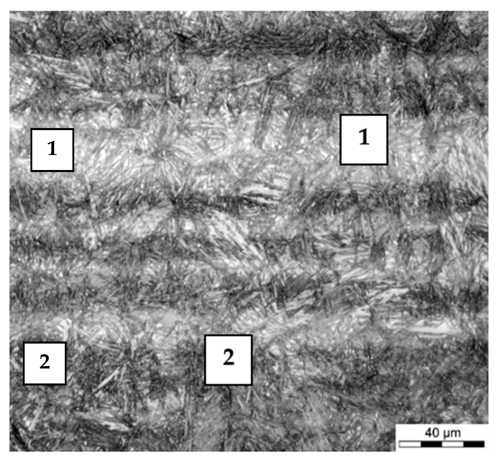
5.1. The Effect of Manufacturing Technology Parameters on the Uniformity of the Examined Material

At the casting stage of the manufacturing process, a material with a primary inter-dendritic segregation is produced. A consequence of primary segregation is the banding of the microstructure especially in the final long and flat products. Through the thickness of the plates there are sequentially distributed areas with different chemical composition and morphology of microstructure components. Representative results illustrating the degree of segregation and microstructural banding in the tested material of heat no. 3 are presented in Table 2 and Figure 1. A similar type of microstructure was observed in plates made of heats no. 1 and no. 2. In nanobainitic steels, elements that tend to segregate during solidification are mainly Mo and Mn. Mo content above 1.30% has been found in the segregation areas, compared to an average Mo content in steel of 0.75%. In fact, changes in the content of elements in neighboring segregated zones are not sharp, and the boundaries between them are characterized by an intermediate chemical composition between the maximum and minimum content of each segregating element. In particular, the differences in the content of elements affect the Ms temperature and the phase transformation kinetics for the applied parameters of heat treatment: austenitizing temperature, cooling rate and isothermal holding temperature determined by dilatometric tests. As a result of the application of constant isothermal transformation temperature, zones of material with different morphology of microstructure (Figure 2, Figure 3 and Figure 4) and hardness (Figure 5) were found which corresponded to segregation zones.
Microstructure and Mo content measurements results in Figure 2 and EBSD measurement results, shown in Figure 4, clearly prove the correlation of microstructure morphology with elemental segregation bands. Figure 3 illustrates the differences in the type of the microstructure of bainite lath packets and in blocky retained austenite content, grain size and morphology. In areas with a higher Mo content compared to the average Mo content in steel, a higher volume fraction of blocky retained austenite and the presence of accumulation of grains of this phase with sizes reaching 3 μm were found. Zones with a higher Mo content are characterized by a lower Ms temperature. In these areas the transformation of austenite to bainite is likely to start and the resulting phases (bainite and retained lathy and blocky austenite) are characterized by larger sizes due to the significant difference between the actual Ms temperature and the applied IHT temperature. At the same time increase the carbon content in the austenite during transformation results in lowering Ms temperature additionally. Then carbon enriched austenite, especially in the areas with higher content of Mo is more thermodynamic stable and finally its volume fraction and grain dimensions are larger compare to the areas of lower content of Mo. Large retained austenite grains may be the cause of crack nucleation sites in plastic deformation processes when phase transformation of the blocky austenite into fresh martensite occurs. These areas also correspond to lower hardness compared to the average hardness of the steel because of high volume fraction of blocky retained austenite (Figure 5).
The material properties depend on the constituents of the microstructure which are critically weak for particular types of external load. In the critical constituents microcracks or local undesirable phenomena associated with the initiation of plastic deformation and/or phase transformation can occur. Most methods of material testing and property measurements are carried out for a representative volume covering at least several segregation zones. In fact, material at the microscale is composed of zones with different properties (Figure 5) and the measurements result in averaged values taking into account the interactions at the borders between the zones. In nanobainitic steels the occurrence of primary segregation of a certain intensity, described as a difference in the content of key alloying elements (Mo, Cr, Mn, and Si) and distance of neighboring bands, may lead to instability of mechanical properties, in particular to a decrease in plasticity.

5.2. Dilatometric Studies

The cooling rate of the supersaturated austenite before the start of IHT and martensite start temperature are the most important factors for the design of production technology of nanobainitic steels. For the investigated material, still air cooling of the products was applied before beginning the isothermal transformation. CCT diagrams of heats no. 2 and 3 determined based on the dilatometric data and microstructure examination results, are shown in Figure 6. The CCT diagram of the material of heat no. 1 was published previously [5]. The critical cooling rates in the temperature range of 600–400 °C, determined from the diagrams, are close to 0.5 °C/s. Microstructure examination confirmed that pearlite formation at prior austenite grains starts at cooling rate of 0.4°C/s (Figure 7). Taking into account the segregation of alloying elements, it was established that a critical cooling rate of 1 °C/s is required to avoid diffusional phase transformations before beginning IHT. Ms temperature determined from dilatometric measurements is close to 200 °C at a cooling rate of 1 °C/s for all of the examined nanobainitic steel grades.

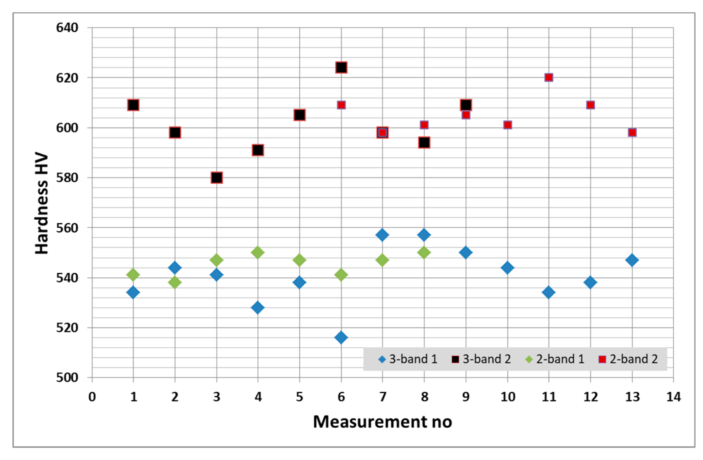
5.3. Mechanical Properties Determined in Quasi-Static Tensile Tests

Nanobainitic steels are characterized by a high tensile strength (UTS) reaching 2200 MPa and total elongation above 10%, however the yield strength (YS0.2) is in the range of 1300–1500 MPa. Although the steels show a wide range of strain hardening during deformation, too low a level of yield strength could limit the potential applications. High strength with acceptable elongation and toughness and a wide range of strain hardening were the reason for using these steels for the manufacture of armor plates.
The criteria for the optimum combination of mechanical properties needed for armor elements were determined using results of quasi-static tensile tests, i.e., values of YS0.2, UTS and TE. For the above-described application, the following properties were required to be met simultaneously: YS0.2 of at least 1300 MPa; UTS of at least 2000 MPa, and TE of at least 10 %. The properties have been defined in order to meet the specified resistance to perforation of plates in multi-hit firing tests. In such applications, uniformity of properties on the surface of the plates is particularly important because the resistance to perforation must be met by every micro-area of the material.
In Figure 8, tensile curves are presented showing the characteristic features of the material depending on the heat treatment parameters. IHT at low-temperature requires time minimum 96 h in order to achieve simultaneously required UTS level and of YS0.2. The use of IHT temperature 225 °C results in a decrease in UTS compare to annealing at 210 °C (Figure 8a,b). The use of shorter heat treatment time, 48, 54, and 72 h for 210 °C, results in a very low YS0.2 value, a very high UTS (UTS/YS0.2 ratio above or close to 2.0), i.e., with a wide range of strain hardening, which leads to total elongation of 11–13% (Figure 8a,c).
The results of measurements of mechanical properties in a quasi-static tensile test for the temperature of isothermal annealing in the range of 200–225 °C and a wide range of holding times from 48 to 144 h are also presented in Table 3. The analysis of the results of quasi-static tensile tests determined the values of temperature and isothermal annealing times which provide the required mechanical properties. Isothermal transformation at temperature in the range of 210–225 °C for corresponding periods of time of 96–120 and 72–96 h guarantees obtaining required mechanical properties for the investigated steels. Application of times shorter than 72 h at temperature of 210 °C results in low YS0.2 (below 1000 MPa) but very high UTS, even above 2200 MPa, at 11% of TE. A similar set of mechanical properties was obtained for the lowest applied temperature of IHT 200 °C even after 120 h of annealing. At 225 °C there is a drop in UTS below 2000 MPa. Figure 9 shows the trend of changes in UTS and YS0.2 for transformation temperatures 210 °C and 225 °C depending on the isothermal annealing time. For a particular heat treatment temperature, an increase in annealing time caused a decrease in UTS, with a simultaneous increase in YS0.2. The extent of changes in UTS and YS0.2 decreases with an increase in treatment time and stabilizes at 210 °C after approx. 90 h, and at 225 °C after 72 h.

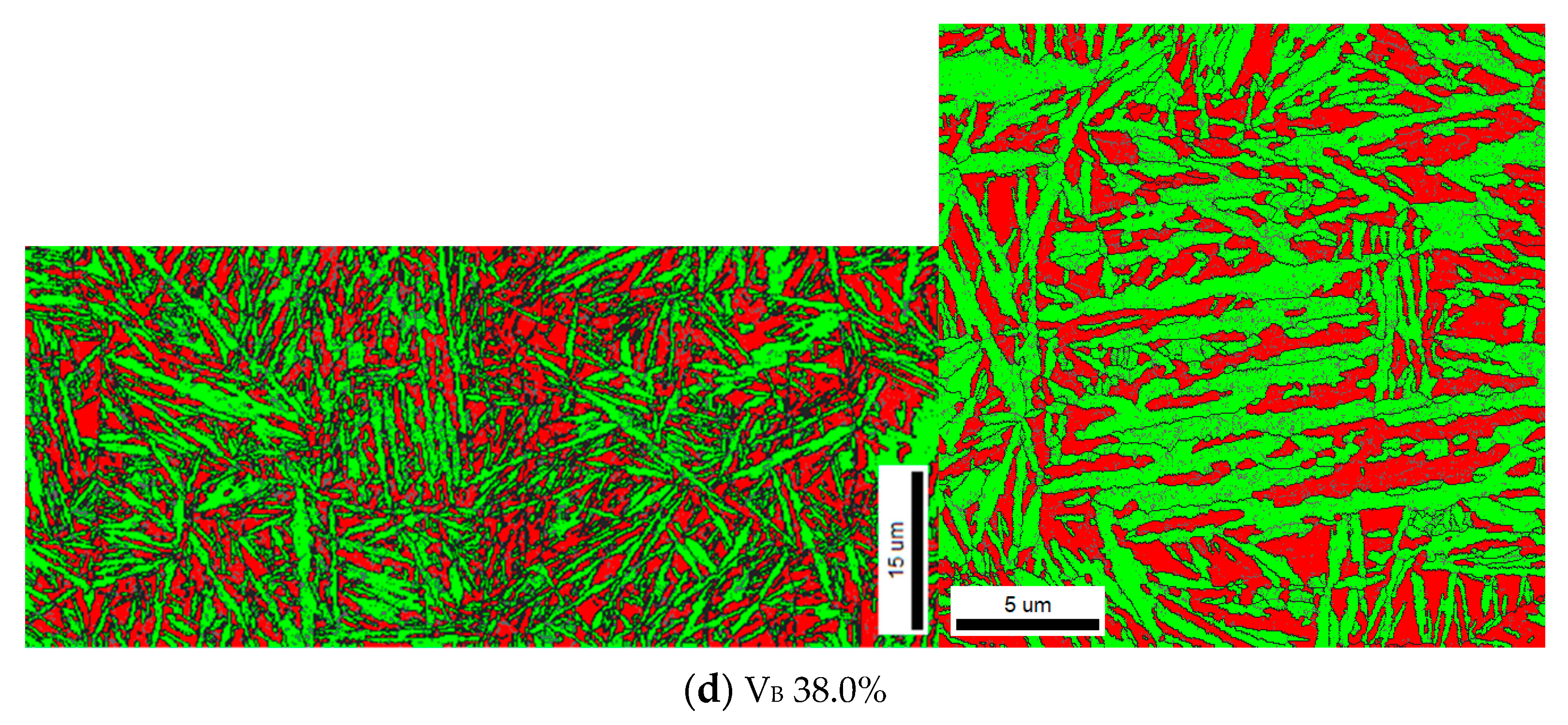
5.4. Morphology, Size Distribution, and Content of Blocky Retained Austenite

The final microstructure of the investigated nanobainitic steels has three main constituents. The matrix is composed of carbideless nanobainite, some of which is tempered depending on the moment of formation, carbon-enriched nanolathy austenite between the nanobainite plates and blocky retained austenite enriched with carbon with different morphologies and grain sizes. Three morphologies of retained austenite were identified: thin layers between laths of bainitic ferrite of thickness below about 100 nm (nanolathy NL) and two forms of blocky retained austenite (B) separating sheaves of laths of bainitic ferrite: polyhedrals and plates of size or thickness between a few tenths of a micron and about 3.0 μm.
The results of measurements of retained austenite content are presented in Table 4. Total retained austenite content, i.e., the content of blocky and nanolathy austenite, was determined by using XRD [30]. The nanolathy austenite content was calculated as the difference between the total austenite content based on XRD and the austenite content determined by SEM-EBSD. It is difficult to find a correlation of temperature and time of isothermal annealing with the content of a particular type of retained austenite (total, blocky and nanolathy). The results for IHT temperature range of 210–225 °C and time of 72–120 h indicated total volume fraction changing from 15 to 27%, blocky retained austenite from 7 to 17% and calculated nanolathy retained austenite from 3.5 to 17%. The results clearly show strong influence of inhomogeneity on local content of particular type of retained austenite.
For short isothermal annealing time (54 h), non-uniform distribution of blocky retained austenite was found, resulting in the presence of local blocky austenite content significantly higher than the average total austenite content. Figure 10 shows non-uniform distribution of blocky retained austenite resulting from segregation in heat no. 1. In the specimens subjected to isothermal transformation at 210 °C, areas with blocky austenite content of 14.5% and 27.2% were found. In those specimens subjected to isothermal transformation at 225 °C areas of 21.6% and 38.0% were found. This shows that determination of blocky austenite content by EBSD can be burdened with a significant measurement error for this type and degree of microstructure heterogeneity.
A high amount of large grains of blocky retained austenite, especially in segregation areas, is the reason for a low YS0.2 value for the specimens transformed at temperatures of 210 °C and 225 °C for 48 h and 54 h. During a quasi-static tensile test, this austenite undergoes a continuous deformation and/or transformation to martensite after exceeding the yield point, causing a wide range of strain hardening and, therefore, leading to high UTS and elongation values. It should be noted that this type of microstructure does not guarantee an acceptable level of impact toughness because high-carbon martensite is formed from the carbon-enriched blocky retained austenite.
Figure 11 and Figure 12 show the results of EBSD analysis of morphology, arrangement, size distribution and mean diameter of grains of blocky retained austenite. Two types of retained austenite morphology were observed under EBSD magnification: polyhedral grains and laths. The width of laths reached a maximum of 3 μm and a maximum length of about 5 μm. Laths with length larger than 2.0 μm occurred occasionally. The polyhedral shaped grains of retained austenite can be divided into two groups. The first is characterized with mean diameter in the range 0.50–1.50 μm. The second has mean diameter in the range 0.10–0.50 μm. Most of the polyhedral grains analyzed were characterized with diameters of 0.20–0.80 μm. The average diameter of all analyzed blocky austenite grains ranged from 0.30 to 0.40 μm.

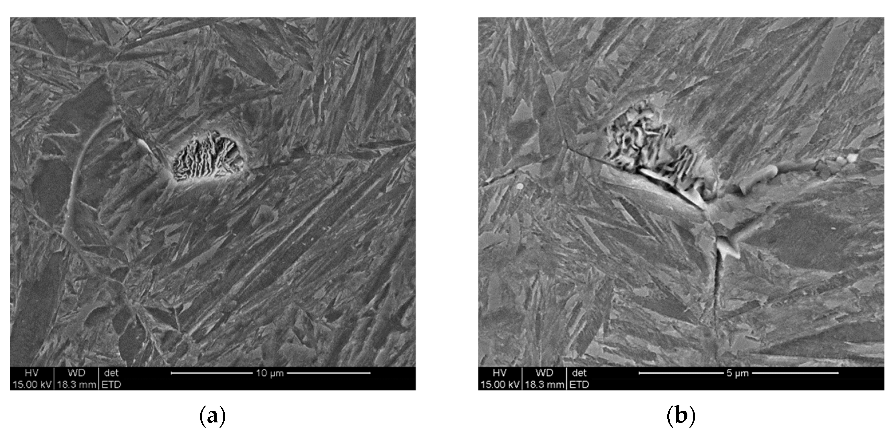
5.5. TEM Examination of the Nanobainite Steel Microstructure

In Figure 13 and Figure 14 the results of microstructure examination using TEM are shown. A lathy type of bainitic microstructure with retained austenite in the form of films between the laths of bainite and in the form of separate polyhedral grains were found. The presence of retained austenite was confirmed by electron diffraction method in microareas (Figure 13b and Figure 14b,d). The average width of the bainite laths was determined to be between dozens to more than 100 nm and the retained austenite film thickness was up to about 50 nm. No carbides were found in the bainite laths at the applied magnification using these methods of investigation.

6. Discussion

The principles of designing the phase composition of nanostructured bainitic steel, with 0.60 wt.% carbon content, providing mechanical properties required for specific applications were presented. The present research was focused on the use of nanobainitic steel for the manufacture of armor plates requiring extremely uniform properties on the plate surface [31,32,33]. The parameters of IHT have been determined, the application of which guarantees obtaining nanobainitic steel with UTS of at least 2000 MPa, YS0.2 of at least 1300 MPa, and TE of at least 10% and acceptable level of toughness. The analysis of the impact strength is the subject of another article. Charpy-V impact strength is in the range of 22–26 J/cm2 and 13–16 J/cm2 at test temperatures +20 °C and −40 °C, respectively, for the optimal heat treatment variants developed in this work.
The microstructure is composed of carbide free nanobainite laths and retained blocky and lathy austenite as confirmed by MS, SEM, and TEM studies. The content and morphology of the individual phases, for defined parameters of IHT, can be controlled to some extent based on the results of isothermal transformation kinetics, XRD and EBSD measurements and calculations of the volume fraction of retained blocky and lathy austenite [9,17,21,27].
A consequence of primary segregation of alloying elements is the banding of the microstructure especially in the final long and flat products. Through the thickness of the plate there are sequentially distributed bands with different chemical composition and morphology of microstructure components. In nanobainitic steels, the elements that tend to segregate during solidification are Mo, Mn, and Cr [34,35]. Changes in the content of elements in neighboring segregated zones are not sharp, and the boundaries between them are characterized by intermediate chemical compositions between the maximum and minimum content of each segregating element. In particular, differences in element content affect the Ms temperature and the phase transformation kinetics for specific values of heat treatment parameters, for example the austenitizing temperature, cooling rate, and isothermal heating temperature and time, determined by dilatometric tests. As a result of the application of constant isothermal transformation temperature, zones of material with different morphology of microstructure and hardness were found which corresponded to segregation zones [34,35]. The properties of the material, especially yield strength and plasticity, depend on the constituents of the microstructure which are critically weak for particular types of external load. In the area of critical constituents microcracks or local undesirable phenomena associated with the initiation of plastic deformation and/or phase transformation can occur. In nanobainitic steels, the occurrence of primary segregation of a certain intensity (described as a difference in the content of key elements: Mo, Cr, Mn, and Si and distance of neighboring bands) may lead to instability of mechanical properties, especially to a decrease in ductility [35].
The content of strongly segregating elements can be reduced only to a certain level due to their influence on hardenability, especially on the critical cooling rate and the Ms temperature [8]. The optimum content of the above-mentioned elements must be found in order to control the degree of segregation and to ensure the proper values of parameters of the manufacturing process, for example the cooling rate before isothermal annealing. Finally, for the defined chemical composition of the nanobainitic steel, it is necessary to determine the range of temperature and time of isothermal transformation that will guarantee the desired strength to elongation ratio at acceptable toughness level.
For the investigated steels containing about 0.60%C it was established, based on the dilatometric studies, that a critical cooling rate of 1 °C/s is required to avoid diffusional phase transformations before reaching the temperature of IHT. Ms temperature determined by dilatometric tests is close to 200 °C at a cooling rate of 1 °C/s for all of the examined nanobainitic steel grades. Transformation characteristics of the steels indicate the possibility of a natural cooling in air of products with cross-sectional dimensions of up to about 15 mm [8]. Moreover, a practically acceptable isothermal annealing time should be provided which depends indirectly on the Ms temperature. Isothermal transformation at temperature range of 210–215 °C for period of time 96–120 h and at 225 °C for period of time 72–96 h guarantees obtaining the required mechanical properties for the tested steels.
Results of retained austenite examination clearly show the strong influence of inhomogeneity on local content of a particular type of retained austenite. Especially for short isothermal annealing time (54 h) at low transformation temperature (210 °C), non-uniform distribution of blocky retained austenite was found, resulting in the presence of local high content of blocky austenite, significantly higher than the average total austenite content. A high amount of large grains of blocky retained austenite, especially in segregation areas, is the cause of a low YS0.2 value. Moreover carbon-enriched retained austenite may transform as a result of external loading into high carbon martensite of low ductility.

7. Conclusions

The aim of the work described in this paper was to design phase composition of nanobainitic steel containing 0.56–0.60%C, 1.68–1.95%Mn, 1.58–1.80%Si, 1.30–1.47%Cr, 0.57–0.75%Mo in order to obtain diversified mechanical properties for specific applications, such as armor plates. Optimal parameters of IHT were determined to produce a microstructure consisting of nanolathy carbideless bainite and blocky and lathy retained austenite which guarantees the following mechanical properties in quasi-static tensile test: UTS of at least 2000 MPa, YS0.2 of at least 1300 MPa, TE of at least 10%.
Isothermal transformation at temperature range of 210–225 °C for corresponding time periods of 96–120 and 72–96 h guarantees obtaining the required mechanical properties for the tested steels at acceptable toughness level. Charpy-V impact strength in the range of 22–26 J/cm2 and 13–16 J/cm2 at temperatures +20 °C and −40 °C, respectively, is achieved.
Total volume fraction of retained austenite at optimal IHT parameters changing from 15 to 27%, blocky retained austenite from 7 to 17% and calculated nanolathy retained austenite from 3.5 to 17%. For the shortest isothermal annealing times (48 and 54 h), non-uniform distribution of blocky retained austenite was found, resulting in the presence of local blocky austenite content significantly higher than the average total austenite content. Non-uniform distribution of blocky retained austenite results from primary segregation.
Based on EBSD analysis of morphology, arrangement, size distribution and mean diameter of grains of retained austenite, two types of blocky retained austenite were observed: polyhedral grains and laths. Most of the analyzed grains of blocky austenite were characterized by a diameter in the range of 0.20–0.80 μm at the average diameter range of 0.30–0.40 μm.
Work is being carried out on optimization of primary structure of the material and isothermal annealing parameters in order to limit the negative impact of chemical segregation on functional properties. The aim of future investigations is to achieve the desired type of microstructure and its uniform distribution throughout the whole volume of material, especially the austenite block-type grains in segregation bands.

Author Contributions

Conceptualization: J.M. and B.G.; methodology: J.M. and B.G.; formal analysis: J.M. and B.G.; investigation: A.J. (EBSD analysis), W.Z. (dilatometric experiments); writing—original draft preparation: J.M. and B.G.; writing—review and editing: J.M. and B.G.; visualization: J.M., W.Z., A.J.; supervision: B.G.; project administration: J.M. All authors have read and agreed to the published version of the manuscript.

Funding

This work was financially supported by The National Centre for Research and Development (POIR-04.01.04-00-0047/16, Project “Development of production technology of light observation-protective container (LOOK) made of nanostructured ultrastrength steels”).

Institutional Review Board Statement

Not applicable.

Informed Consent Statement

Not applicable.

Data Availability Statement

Not applicable.

Conflicts of Interest

The authors declare no conflict of interest.

References

  1. Caballero, F.G.; Bhadeshia, H.K.D.H.; Mawella, K.J.A.; Jones, D.G.; Brown, P. Very strong low temperature bainite. Mat. Sci. Technol. 2002, 18, 279–284. [Google Scholar] [CrossRef] [Green Version]
  2. Wenyan, L.; Jingxin, Q.; Hesheng, S. Fatigue crack growth behaviour of a Si–Mn steel with carbide-free lathy bainite. J. Mat. Sci. 1997, 32, 427–430. [Google Scholar] [CrossRef]
  3. Caballero, F.G.; Bhadeshia, H.K.D.H. Very strong bainite. Curr. Opin. Solid State Mat. Sci. 2004, 8, 251–257. [Google Scholar] [CrossRef] [Green Version]
  4. Garbarz, B.; Burian, W. Microstructure and Properties of Nanoduplex Bainite-Austenite Steel for Ultra-High-Strength Plates. Steel Res. Int. 2014, 85, 1620–1628. [Google Scholar] [CrossRef]
  5. Garbarz, B.; Niżnik-Harańczyk, B. Modification of microstructure to increase impact toughness of nanostructured bainite-austenite steel. Mat. Sci. Technol. 2015, 31, 773–780. [Google Scholar] [CrossRef]
  6. Marcisz, J.; Burian, W.; Janiszewski, J.; Rozmus, R. Microstructural changes of the nanostructured bainitic steel induced by quasi-static and dynamic deformation. Arch. Met. Mat. 2017, 62, 2317–2329. [Google Scholar] [CrossRef] [Green Version]
  7. Marcisz, J.; Janiszewski, J. Mechanical behaviour of nanostructured bainitic steel under high strain shear and compression loading. Arch. Met. Mat. 2019, 64, 1151–1162. [Google Scholar]
  8. Garbarz, B.; Marcisz, J.; Burian, W. Technological peculiarities of manufacturing nanobainitic steel plates. In Proceedings of the METEC & ESTAD Conference, Düsseldorf, Germany, 15–19 June 2015. [Google Scholar]
  9. Garcia-Mateo, C.; Caballero, F.G. The Role of Retained Austenite on Tensile Properties of Steels with Bainitic Microstructures. Mat. Trans. 2005, 46, 1839–1846. [Google Scholar] [CrossRef] [Green Version]
  10. Timokhina, B.; Beladi, H.; Xiong, X.X.; Adachi, Y.; Hodgson, P.D. Nanoscale microstructural characterization of a nanobainitic steel. Acta Mat. 2011, 59, 5511–5522. [Google Scholar] [CrossRef]
  11. Garcia-Mateo, C.; Caballero, F.G.; Sourmail, T.; Kuntz, M.; Cornide, J.; Smanio, V.; Elvira, R. Tensile behavior of a nanocrystalline bainitic steel containing 3wt% silicon. Mat. Sci. Eng. A 2012, 549, 185–192. [Google Scholar] [CrossRef] [Green Version]
  12. Beladi, H.; Timokhina, I.B.; Hodgson, P.D. Characterization of nano-structured bainitic steel. Int. J. Mod. Phys. Conf. 2012, 5, 1–8. [Google Scholar] [CrossRef]
  13. Avishan, B.; Garcia-Mateo, C.; Morales-Rivas, L.; Yazdani, S.; Caballero, F.G. Strengthening and mechanical stability mechanisms in nanostructured bainite. J. Mater. Sci. 2013, 48, 6121–6132. [Google Scholar] [CrossRef] [Green Version]
  14. Avishan, B.; Garcia-Mateo, C.; Morales-Rivas, L.; Yazdani, S.; Caballero, F.G. Retained austenite thermal stability in a nanostructured bainitic steel. Mat. Charact. 2013, 81, 105–110. [Google Scholar] [CrossRef] [Green Version]
  15. Babu, S.S.; Vogel, S.; Garcia-Mateo, C.; Clausen, B.; Morales-Rivas, L.; Caballero, F.G. Microstructure Evolution during Tensile Deformation of a Nanostructured Bainitic Steel. Scr. Mat. 2013, 69, 777–780. [Google Scholar] [CrossRef] [Green Version]
  16. Caballero, F.G.; Miller, M.K.; Garcia-Mateo, C. Opening previously impossible avenues for phase transformation in innovative steels by atom probe tomography. Mater. Sci. Technol. 2014, 30, 1034–1039. [Google Scholar] [CrossRef] [Green Version]
  17. Morales-Rivas, L.; Yen, H.-W.; Huang, B.-M.; Kuntz, M.; Caballero, F.G.; Yang, J.-R.; Garcia-Mateo, C. Tensile Response of Two Nanoscale Bainite Composite-Like Structures. JOM 2015, 67, 2223–2235. [Google Scholar] [CrossRef]
  18. Tsai, Y.T.; Chang, H.T.; Huang, B.M.; Huang, C.Y.; Yang, J.R. Microstructural characterization of Charpy-impact-tested nanostructured bainite. Mat. Charact. 2015, 107, 63–69. [Google Scholar] [CrossRef]
  19. Hulme-Smith, C.N.; Peet, M.J.; Lonardelli, I.; Dippel, A.C.; Bhadeshia, H.K.D.H. Further evidence of tetragonality in bainitic ferrite. Mater. Sci. Technol. 2015, 31, 254–256. [Google Scholar] [CrossRef] [Green Version]
  20. Pereloma, E.V. Critical assessment: On carbon excess in bainitic ferrite. Mater. Sci. Technol. 2016, 32, 99–103. [Google Scholar] [CrossRef] [Green Version]
  21. Caballero, F.G.; Rementeria, R.; Morales-Rivas, L.; Benito-Alfonso, M.; Yang, J.-R.; De Castro, D.; Poplawsky, J.D.; Sourmail, T.; Garcia-Mateo, C. Understanding Mechanical Properties of Nano-Grained Bainitic Steels from Multiscale Structural Analysis. Metals 2019, 9, 426. [Google Scholar] [CrossRef] [Green Version]
  22. Bhadeshia, H.K.D.H. Properties of Fine–Grained Steels Generated by Displacive Transformation. Mat. Sci. Eng. A 2008, 481–482, 36–39. [Google Scholar] [CrossRef] [Green Version]
  23. El Fallah, G.; Bhadeshia, H.K.D.H. Tensile behaviour of thermally-stable nanocrystalline bainitic-steels. Mat. Sci. Eng. A 2019, 746, 145–153. [Google Scholar] [CrossRef]
  24. Bhadeshia, H.K.D.H. Bainite in Steels: Theory and Practice, 3rd ed.; Money Publishing: Leeds, UK, 2015. [Google Scholar]
  25. Morales-Rivas, L.; Garcia-Mateo, C.; Kuntz, M.; Sourmail, T.; Caballero, F.G. Induced martensitic transformation during tensile test in nanostructured bainitic steels. Mat. Sci. Eng. A 2016, 662, 169–177. [Google Scholar] [CrossRef] [Green Version]
  26. Morales-Rivas, L.; Garcia-Mateo, C.; Sourmail, T.; Kuntz, M.; Rementeria, R.; Caballero, F.G. Ductility of Nanostructured Bainite. Metals 2016, 6, 302. [Google Scholar] [CrossRef]
  27. Sourmail, T.; Garcia-Mateo, C.; Caballero, F.G.; Morales-Rivas, L.; Rementeria, R.; Kuntz, M. Tensile Ductility of Nanostructured Bainitic Steels: Influence of Retained Austenite Stability. Metals 2017, 7, 31. [Google Scholar] [CrossRef] [Green Version]
  28. Bhadeshia, H.K.D.H. TRIP-Assisted Steels? ISIJ Int. 2002, 42, 1059–1060. [Google Scholar] [CrossRef] [Green Version]
  29. Andrews, K.W. Empirical formulae for the calculation of some transformation temperatures. J. Iron Steel Inst. 1965, 203, 721–727. [Google Scholar]
  30. Saha Podder, A.; Lonardelli, I.; Molinari, A.; Bhadeshia, H.K.D.H. Thermal stability of retained austenite in bainitic steel: In situ study. Proc. R. Soc. A 2011, 467, 3141–3156. [Google Scholar] [CrossRef] [Green Version]
  31. Borvik, T.; Dey, S.; Clausen, A.H. Perforation resistance of five different high-strength steel plates subjected to small-arms projectiles. Int. J. Impact Eng. 2009, 36, 948–964. [Google Scholar] [CrossRef]
  32. Kolla, H.H.; Mishra, B.; Jena, P.K.; Siva Kumar, K.; Bhat, T.B.; Srinivas, M.; Reddy, A.V. Development of an ultrahigh strength low alloy steel for armour applications. Mat. Sci. Technol. 2011, 27, 551–555. [Google Scholar] [CrossRef]
  33. Jena, P.K.; Ponguru Senthil, P.; Siva Kumar, K. Effect of tempering time on the ballistic performance of a high strength armour steel. J. Appl. Res. Technol. 2016, 14, 47–53. [Google Scholar] [CrossRef]
  34. Khan, S.A.; Bhadeshia, H.K.D.H. The bainite transformation in chemically heterogenous 300 M high-strength steel. Metall. Trans. A 1990, 21, 859–875. [Google Scholar] [CrossRef]
  35. Basso, A.; Eres-Castellanos, A.; Tenaglia, N.; San-Martin, D.; Jimenez, J.A.; Caballero, F.G. Effect of Microsegregation and Bainitic Reaction Temperature on the Microstructure and Mechanical Properties of a High-Carbon and High-Silicon Cast Steel. Metals 2021, 11, 220. [Google Scholar] [CrossRef]
Figure 1. Microstructure through the thickness of plate made of nanobainitic steel. IHT at 215 °C for 96 h, heat no. 3 light microscope.
Metals 11 00658 g001
Figure 2. EDX mapping of the Mo distribution in the segregation band (a) and corresponding microstructure of the band (b). IHT at 215 °C for 96 h, heat no. 3, SEM, longitudinal section.
Metals 11 00658 g002
Figure 3. Microstructure in the segregation bands. IHT at 215 °C for 96 h, heat no. 3, SEM, longitudinal section. (a)-1, (b)-2—areas corresponding to those indicated in Figure 1 and Figure 2.
Metals 11 00658 g003
Figure 4. Blocky retained austenite inhomogeneity in the segregation bands. IHT at 215 °C for 96 h, heat no. 3, SEM—EBSD maps.
Metals 11 00658 g004
Figure 5. Hardness measurements results along segregation bands. Average hardness of the steel is 610 HV. Heat no. 2 (210–225 °C/120–72 h) and heat no. 3 (200–225 °C/144–72 h). Band 1, band 2—numbers correspond to those indicated in Figure 1, Figure 2, Figure 3 and Figure 4.
Metals 11 00658 g005
Figure 6. CCT diagrams of the examined steels: (a) heat no. 2, (b) heat no. 3. CR—cooling rate, HV10—Vickers hardness at 10 kgf.
Metals 11 00658 g006
Figure 7. Microstructure of the examined steels at cooling rate 0.4 °C/s. Heats no. 2 (a) and no. 3 (b).
Metals 11 00658 g007
Figure 8. Engineering stress-strain curves of nanobainitic steel obtained from quasi-static tensile tests. (a) heat no. 1, IHT at 210 °C; (b) heat no. 1, IHT at 225 °C; (c) heat no. 3, IHT at 210 °C.
Metals 11 00658 g008
Figure 9. YS0.2 and UTS vs. time of IHT at 210 and 225 °C. Nanobainitic steel, heat no. 1 (a,b) and heat no. 3 (c).
Metals 11 00658 g009aMetals 11 00658 g009b
Figure 10. Blocky retained austenite and bainite packets in the specimen after IHT. Heat no. 1, (a,b) 210 °C/54 h, (c,d) 225 °C/54 h. Phase distribution maps, EBSD, SEM.
Metals 11 00658 g010aMetals 11 00658 g010b
Figure 11. Bainite packets and blocky retained austenite grains morphology (a,b) and size distribution (c). Heat no. 2, 215 °C/96 h, EBSD maps, SEM. Number of analyzed grains 463, average diameter 360 nm.
Metals 11 00658 g011
Figure 12. Bainite packets and blocky retained austenite grains morphology (a,b) and size distribution (c). Heat no. 3, 210 °C/96 h, EBSD maps, SEM. Number of analyzed grains 385, average diameter 370 nm.
Metals 11 00658 g012
Figure 13. Example of a bright (a,c) and dark (b,d) field TEM micrographs and electron diffraction pattern of the retained austenite film (b). Heat no. 1, (a,b) 210 °C/120 h and (c,d) 225 °C/72 h.
Metals 11 00658 g013
Figure 14. Examples of a bright (a,c) and dark field (b,d) TEM micrographs and electron diffraction patterns of the retained austenite film (b) and block grain (d). Heat no. 2, 215 °C/96 h.
Metals 11 00658 g014aMetals 11 00658 g014b
Table 1. Chemical composition of investigated steels and calculated Ms temperature, wt%.
Heat No.*CMnSiPSCrMoAlMs **
°C
10.581.951.800.0100.0041.300.670.018200
20.601.681.580.0120.0041.410.570.022201
30.561.821.740.0170.0041.470.750.025210
* 1-industrial heat (flat ingots); 2 and 3-industrial heats (polygonal forging ingots). ** Ms (°C) = 539 − 423%C − 30.4%Mn − 12.1%Cr − 7.5(%Si + %Mo) [29].
Table 2. Results of chemical analysis in the segregation bands and calculated Ms temperature for the bands. Plate made of nanobainitic steel, industrial heat no. 3.
ElementElement Content, wt%
Area 1
(Figure 1, Figure 2, Figure 3 and Figure 4)
Area 2
(Figure 1, Figure 2, Figure 3 and Figure 4)
Si1.75–2.051.55–1.80
Mo1.05–1.350.60–0.70
Cr1.60–1.901.45–1.50
Mn1.40–1.601.15–1.40
Ms, (at 0.56%C)219–205 °C233–223 °C
Table 3. Mechanical properties determined in quasi-static tensile test.
Parameters of IHT, Temp. °C/Time hYS0.2
MPa
Std. Dev.
YS0.2
UTS
MPa
Std. Dev.
UTS
TE
%
Std. Dev.
TE
UTS/YS0.2
Heat no. 1
200/120108818.5212712.010.83.101.95
210/5482225.4225314.711.52.722.74
210/72112523.6215718.713.11.561.92
210/96126728.7214715.611.71.921.69
210/120133024.1204524.612.51.261.54
210/144135622.620239.614.31.801.49
225/54123129.7204616.811.72.481.66
225/72136617.019365.715.21.201.42
225/96137225.2190320.914.51.041.38
225/120136314.3192210.114.30.761.41
225/144132220.8198415.814.21.251.50
Heat no. 2
210/96137619.120476.813.70.831.49
210/120150818.120687.115.21.221.37
215/96149020.4206313.311.90.641.38
220/96138013.720118.912.30.171.46
225/72140527.620002.314.50.421.42
Heat no. 3
210/4898823.5219912.413.21.682.23
210/72115321.7215816.712.01.531.87
210/96132817.920329.814.60.721.53
210/120138726.920002.114.20.571.44
215/9613206.7198310.014.60.721.50
220/96139418.8198212.413.31.101.42
225/72134312.3194711.514.80.721.45
Table 4. Results of volume fraction of retained austenite measurements (blocky (VB) and total (VB+NL)) and calculation of nanolathy retained austenite content (VNL).
Heat no. -
IHT Parameters, Temp., °C/Time, h
Volume Fraction of Retained Austenite, %
VB+NL
(XRD)
VB
(EBSD)
VNL
(VB+NL-VB)
1-210/5423.314.5/27.0 **
1-210/9626.710.016.7
1-210/12018.313.05.3
1-225/5426.821.6/38.0 **
1-225/7226.813.013.8
1-225/9621.017.04.0
2-210/9614.510.34.2
2-210/12014.99.45.5
2-215/9614.811.33.5
2-225/7217.511.85.7
3-210/4822.58.114.4
3-210/7220.66.014.6
3-210/9615.510.25.3
3-210/12022.610.911.7
3-215/9625.09.815.2
3-225/7215.66.98.7
* selected areas within the segregation bands (shown in Figure 10).
Publisher’s Note: MDPI stays neutral with regard to jurisdictional claims in published maps and institutional affiliations.

