1. Introduction
The use of aluminum (Al) alloys has greatly increased over the past two decades for the production of lightweight powertrain components such as transmission gearcases and engines used in automobiles and marine crafts. The capability of producing lightweight components with complex geometries is one of the most desirable characteristics of Al powertrain alloys. For applications that operate at ambient temperatures, the hypoeutectic A356 (Al–Si–Mg-based) alloy is commonly used. Some of the reasons for its popularity include great castability, sufficient strength, and its responsiveness to chemical modification and/or heat treatment. Elements such as phosphorus (P), strontium (Sr), sodium (Na), and barium (Ba) may be added to refine the alloy’s microstructure by suppressing the growth of specific phases or altering the structure of the phase into a more coherent morphology. Sr is the most common modifier because it is less reactive as compared to the other elements [
1]. The addition of Sr to Al–Si alloys can refine the eutectic Si particles from coarse flakes to a more fine and fibrous structure, which improves the alloy’s strength [
2,
3]. In addition to chemical refinement, solutionizing has been shown to fragment and spheroidize the Si particles in 0.5–4 h, depending on the state of the Al–Si alloy (i.e., modified or not) as well as solutionizing temperature [
2,
3,
4]. The semi-spherical shape of the modified Si particles reduces stress concentrations and improves the alloy’s yield strength (YS) and ultimate tensile strength (UTS) [
5]. A study performed by R. Chen et al. investigated the effects of quenching as well as a T6 heat treatment on the mechanical properties an Al–7 wt.%Si–Mg cast alloy [
2]. Their results indicated that a 2 h solution treatment at 535 °C followed by quenching leads to an increase in the YS and UTS elongation as compared to the as-cast state. These improved properties are likely associated with the homogenization of the solute atoms, an alteration to the eutectic Si morphology, and the dissolution of weakening intermetallics. After artificial aging and completing the T6 temper, a significant increase in both the YS and UTS was observed; however, a reduction in the elongation also occurred. The increase in strength was likely attributed to the precipitation of nano-sized phases, and the decrease in elongation may be associated to the further spheroidization of eutectic Si [
5].
Combating the demand for higher performance and greater efficiencies amongst the marine industry, Mercury Marine has developed a new lightweight Al alloy, Mercalloy A362™ [
6], which they have used for the lower transmission gearcase on one of Mercury Marine’s high-powered outboard engines. The high Si content (~11 wt.%, as compared to ~7 wt.% for A356), was expected to improve the alloy’s strength and allowed for up to 33% thinner walls. Not only did the thinner walls lighten the gearcase, but the lower density also accompanied by the increased Si content further lowered the total weight of the component, as compared to its predecessor which utilized an A356 type alloy. The Mercalloy A362™ alloy was purposely developed to improve the efficiency of the marine craft (via weight reduction) and to improve the alloy’s castability, machinability, and recyclability. The castability of the alloy was improved, as compared to A356, by raising the Si content closer to the eutectic Si composition, thereby providing a near-instantaneous solidification of the molten alloy [
6]. The recyclability of the alloy was improved by using 100% recycled materials and limiting the individual wt.% of each solute element. Limiting the compositional requirement for the alloying elements promotes the re-melting of scrap material, thereby lowering waste, costs, and energy consumption.
Although the alloy’s performance was expected to be superior to the A356 alloy, during the rigorous preliminary testing a few of the as-cast prototype gearcases failed unexpectedly due to the development of a macro crack. This was believed to be caused by the development of high residual stresses during the HPDC process. As a result, the current authors performed a comprehensive residual stress analysis using neutron diffraction on the as-cast and T5 heat-treated transmission gearcases; the results are presented elsewhere [
7]. It was observed that the peak magnitude of residual stress reached nearly 120 MPa in the as-condition, accounting for a large magnitude of the material’s expected strength. Fortunately, approximately half of the maximum residual stress was alleviated after applying the T5 heat treatment. Although the residual stress profiles of the gearcase were described, and it was determined that applying the T5 heat treatment would be a sufficient method for minimizing the likelihood of a crack forming, it was unclear what caused the alleviation of residual stress. Moreover, the effects from microstructural variations and/or defects were not discussed in detail. Microstructural defects such as porosity or intermetallics with harmful morphologies can act as stress concentrators, and can act as crack initiation sites [
8,
9], thereby decreasing the alloy’s toughness and fatigue strength.
In general, the HPDC process consists of forcing molten metal into a metal die cavity by means of external pressure. After the metal solidifies, the die is opened, and the casting is ejected. Due to the relatively high applied pressure (~10–175 MPa), the casting has a near-net finish which reduces the amount of post-processing machining. Moreover, the applied pressure allows manufacturers to produce castings with relatively thin wall sections (i.e., <4 mm), which can result in the production of lightweight components. For HPDC aluminum, a steel mold is commonly used to generate greater cooling rates as compared to other casting methods such as sand casting. As a result, HPDC alloys typically have higher Fe content to minimize the likelihood of the casting sticking to the die. However, relatively high Fe concentrations usually lead to the formation of two harmful Fe-bearing intermetallics, specifically Al
5FeSi and Al
8FeMg
3Si
6 [
10]. The brittleness and poor morphology of these Fe-bearing phases commonly leads to a decrease in the alloy’s fracture toughness. To add to this, the high velocity (~20–80 m/s [
11]) of molten metal that is forced into the die cavity often leads to turbulent flow, and as a result entraps gas and leads to elevated levels of porosity, further increasing stress concentrations and lowering the mechanical properties of the alloy.
Thus, to determine if microstructural defects contributed to the initiation of the crack, this research analyzed the microstructure of the new A362 alloy at several critical locations in the marine transmission gearcases. Moreover, the effects that the T5 heat treatment has on the microstructure and mechanical properties of the A362 alloy are also described.
4. Tensile Properties
A summary of the tensile test results for the as-cast gearcase is presented below in
Table 6. Due to the complex curvature and small wall thickness of the Wall location (AW/TW), tensile samples could not be extracted from this location.
The AR location had the greatest mechanical properties as compared to the other locations. This is likely due the faster cooling rate, leading to smaller grain sizes and the lowest volume fraction of porosity (see
Table 3). The AS sample had visible porosity after machining, which effectively lowers the cross-sectional area and is believed to be the primary cause for the poor tensile performance. It should be noted that the AS sample broke before 0.2% strain was achieved, and thus the YS could not be obtained. The engineering stress–strain curves for each sample are shown below in
Figure 13.
Compared to the as-cast tensile properties of an A356 alloy [
33,
34], the A362 alloy had a much higher YS (163–167 vs. 97–104 MPa) but a considerably lower UTS (178–205 vs. 240 MPa). This is likely attributed to the higher volume fraction of porosity in HPDC A362 samples. Porosity has less of an effect on the YS of Al alloys but has a much more pronounced effect on the UTS and elongation [
35]. In addition to porosity, the relatively high volume fraction of needle-like Al
8FeMg
3Si
6 precipitates (see
Figure 2,
Figure 3,
Figure 4 and
Figure 5 and
Table 3) promotes stress concentrations, and the high aspect ratio increases the interfacial energy between the precipitate and the matrix. As a result, the phase acts a crack initiation site and lowers the alloy’s ductility [
36]. Moreover, the formation of the Al
8FeMg
3Si
6 phase consumes a large portion of the available Mg for forming the more desirable intermetallic Mg
2Si, which is the predominant phase that improves the strength of Al–Si–Mg alloys following heat treatment [
37,
38].
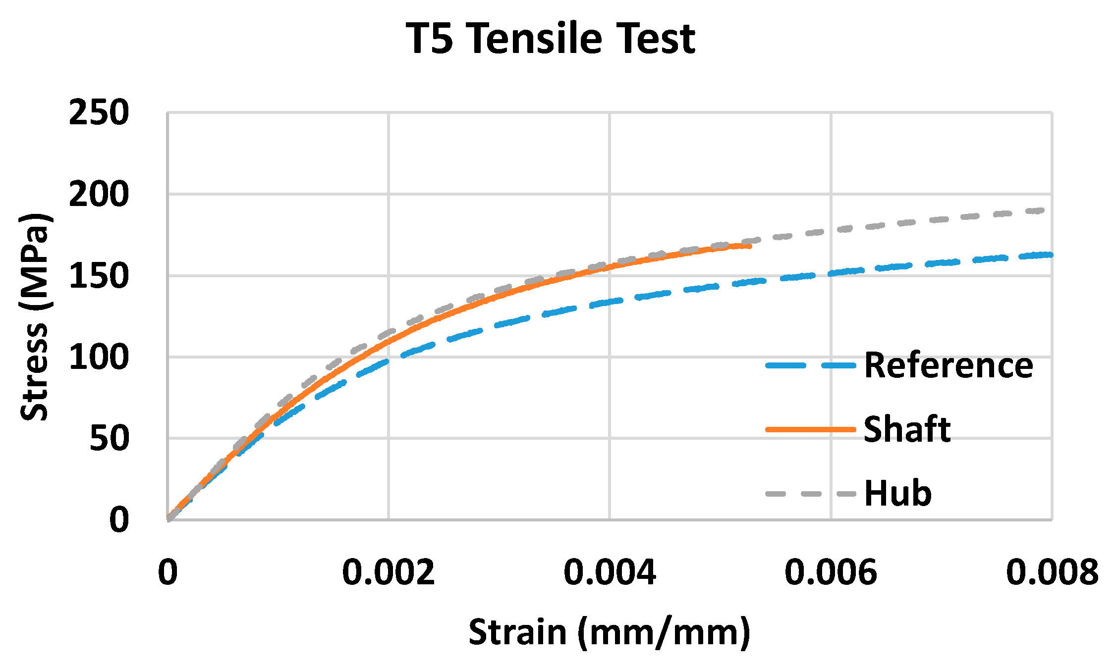
The tensile test results for the T5 heat-treated gearcase are shown below in
Table 7, and the engineering stress–strain curves are displayed in
Figure 14. The results follow a similar trend to the as-cast samples. Compared with the as-cast samples, the TR location had a slightly improved YS and elongation, following by TH, and finally TS which had the poorest performance.
Similar to the as-cast gearcase, the quicker cooling and lower volume fraction of porosity is believed to be the primary causes for the improved tensile performance of the TR sample, as compared the TS and TH specimen. Moreover, the presence of shrinkage porosity near the Al
2Si
2Sr intermetallics (see
Figure 12) in the TS sample is also believed to be one of the reasons for the impaired performance of this specimen.
The similar microstructures and mechanical properties between the as-cast and T5 A362 alloy suggest that Mercury Marine’s specific heat treatment did not lead to any property improvements via modification of the intermetallics. It is likely that that the solutionizing temperature and time are lower than those required to modify the microstructure. Similar to the results presented by P. Cavalier et al. and L. BoChao et al. [
33,
34], the YS and UTS of an A356 alloy were insignificantly affected by a 160–200 °C aging process until the time was increased well above 2–4 h (which is economically unfeasible for mass production). In addition, the relatively high volume fraction of Al
8FeMg
3Si
6 precipitates in the A362 alloy consumed a large portion of the available Mg for forming Mg
2Si during the T5 heat treatment [
37,
38]. The lack of Mg
2Si in the microstructure of the T5–A362 samples supports this claim. This is believed to be the primary reason for the similar tensile properties between the as-cast and T5 heat-treated samples.
The lack of microstructural changes following the T5 heat treatment suggests that the T5 heat treatment likely alleviates the stress via plastic deformation caused by the residual stress surpassing the material’s temperature sensitive yield strength during the solutionizing and subsequent aging portion of the T5 heat treatment.
Author Contributions
Conceptualization, D.S. and T.H.; methodology, J.S. and D.S.; validation, J.S. and D.S.; formal analysis, J.S. and D.S.; investigation, J.S., D.S., T.H., K.A. and A.M.; resources, D.S., T.H., K.A. and A.M.; data curation, J.S. and D.S.; writing—original draft preparation, J.S.; writing—review and editing, J.S., D.S., T.H., K.A. and A.M.; visualization, J.S. and D.S.; supervision, D.S.; project administration, T.H.; funding acquisition, D.S. and T.H. All authors have read and agreed to the published version of the manuscript.
Funding
This research received no external funding.
Institutional Review Board Statement
Not applicable.
Informed Consent Statement
Not applicable.
Data Availability Statement
The raw data required to reproduce the tensile results are available to download from Mendeley Data [“Data for Mercury Marine Gearcase”,
http://dx.doi.org/10.17632/mwkt65b7jn.1] (accessed on 28 February 2021).
Conflicts of Interest
The authors declare no conflict of interest.
References
- Radjai, A.; Miwa, K. Effects of the intensity and frequency of electromagnetic vibrations on the microstructural refinement of hypoeutectic Al-Si alloys. Metall. Mater. Trans. A 2000, 31, 755–762. [Google Scholar] [CrossRef]
- Chen, R.; Xu, Q.; Guo, H.; Xia, Z.; Wu, Q.; Liu, B. Correlation of solidification microstructure refining scale, Mg composition and heat treatment conditions with mechanical properties in Al-7Si-Mg cast aluminum alloys. Mater. Sci. Eng. A. 2017, 685, 391–402. [Google Scholar] [CrossRef]
- Zeren, M. The effect of heat-treatment on aluminum-based piston alloys. Mater. Des. 2006, 28, 2511–2517. [Google Scholar] [CrossRef]
- Lados, D.A.; Apelian, D.; Wang, L. Solution Treatment Effects on Microstructure and Mechanical Properties of Al-(1 to 13 pct)Si-Mg Cast Alloys. Metall. Mater. Trans. B 2011, 42, 171–180. [Google Scholar] [CrossRef] [Green Version]
- Li, R.X.; Li, R.D.; Zhao, Y.H.; Li, C.X.; Sun, X.F.; Guan, H.R.; Hu, Z.Q. Effect of heat treatment on eutectic silicon morphology and mechanical property of Al-Si-Cu-Mg cast alloys. Trans. Nonferrous Met. Soc. China 2004, 14, 496–500. [Google Scholar]
- Mercalloy High Fatigue Strength Aluminum Alloy for Die Casting Alloy 362 Mercalloy, Mercury Marine. Available online: https://www.mercalloy.com/mercalloy-family/high-fatigue (accessed on 13 August 2018).
- Stroh, J.; Sediako, D. Residual stress characterization for marine gear cases in as-cast and T5 heat treated conditions with application of neutron diffraction. In Light Metals; Springer: Cham, Switzerland, 2019; pp. 395–399. [Google Scholar]
- Poolperm, P.; Nakkiew, W. Effect of Porosity on Residual Stress of 2024-Aluminum GTAW Specimen. Mater. Sci. Forum 2016, 872, 28–32. [Google Scholar] [CrossRef]
- Gao, Y.; Yi, J.; Lee, P.; Lindley, T. The effect of porosity on the fatigue life of cast aluminium-silicon alloys. Fatigue Fract. Eng. Mater. Sturct. 2004, 27, 559–570. [Google Scholar] [CrossRef]
- Belov, N.; Aksenov, A.; Eskin, D. Iron in Aluminum Alloys: Impurity and Alloying Element; Taylor & Francis: London, UK, 2002. [Google Scholar]
- Gunasegaram, D.R.; Finnin, B.R.; Polivka, F.B. Melt flow velocity in high pressure die casting: Its effect on microstructure and mechanical properties in an Al-Si alloy. Mater. Sci. Technol. 2007, 23, 847–856. [Google Scholar] [CrossRef]
- Vandersluis, E. Influence of Solidification Parameters on Thermal Conductivity of Cast A319 Aluminum Alloy. Master’s Thesis, Ryerson University, Toronto, ON, Canada, 2016. [Google Scholar]
- Karlsruhe, F. Inorganic Crystals Structures Database. Leibniz Institute for Information Infrastructure. 2018. Available online: https://icsd.fiz-karlsruhe.de/search/index.xhtml;jsessionid=BDB6DC046A694F77D5D5C443909832EF (accessed on 20 June 2017).
- ASTM. E8M Standard Test Methods for Tension Testing Wrought and Cast Aluminum- and Magnesium-Alloy Products; ASTM International: West Conshohocken, PA, USA, 2009; pp. 1–16. [Google Scholar]
- Farina, M.E.; Bell, P.; Ferreira, C.R.F.; Dedavid, B.A. Effects of Solidification Rate in the Microstructure of Al-Si5Cu3 Aluminum Cast Alloy. Mater. Res. 2017, 20, 8–11. [Google Scholar] [CrossRef] [Green Version]
- Shi, Z.; Wang, Q.; Shi, Y.; Zhao, G.; Zhang, R. Microstructure and Mechanical Properties of Gd-Modified A356 Aluminum Alloys. J. Rare Earths 2015, 33, 1004–1009. [Google Scholar] [CrossRef]
- Mao, F.; Yan, G.; Xuan, Z.; Cao, Z.; Wang, T. Effect of Eu Addition on the Microstructures and Mechanical Properties of A356 Aluminum Alloys. J. Alloys Compd. 2015, 650, 896–906. [Google Scholar] [CrossRef]
- Liu, W.; Xiao, W.; Xu, C.; Liu, M.; Ma, C. Synergistic Effects of Gd and Zr on Grain Refinement and Eutectic Si Modification of Al-Si Cast Alloy. Mater. Sci. Eng. A 2017, 693, 93–100. [Google Scholar] [CrossRef]
- Wu, Y.; Zhang, J.; Liao, H.; Li, G.; Wu, Y. Development of High Performance Near Eutectic Al-Si-Mg Alloy Profile by Micro Alloying with Ti. J. Alloys Compd. 2016, 660, 141–147. [Google Scholar] [CrossRef]
- Mbuya, T.O.; Odera, B.O.; Ng’ang’a, S.P. Influence of iron on castability and properties of aluminium silicon alloys: Literature review. Int. J. Cast Met. Res. 2003, 16, 451–465. [Google Scholar] [CrossRef]
- Taylor, J.A. Iron-Containing Intermetallic Phases in Al-Si Based Casting Alloys. Procedia Mater. Sci. 2012, 1, 19–33. [Google Scholar] [CrossRef] [Green Version]
- Bangyikhan, K. Effects of Oxide film, Fe-rich phase, Porosity and their Interactions on Tensile Properties of Cast Al-Si-Mg Alloys. Ph.D. Thesis, University of Birmingham, Birmingham, UK, 2005. [Google Scholar]
- ASTM. E562-02 ASTM Standard Test Method for Determining Volume Fraction by Systematic Manual Point Count; ASTM International: West Conshohocken, PA, USA, 2002; pp. 1–7. [Google Scholar]
- Brauer, S.A.; Whittington, W.R.; Johnson, K.L.; Li, B.; Rhee, H.; Allison, P.G.; Crane, C.K.; Horstemeyer, M.F. Strain Rate and Stress-State Dependence of Gray Cast Iron. J. Eng. Mater. Technol. 2017, 139, 1–11. [Google Scholar] [CrossRef] [Green Version]
- Fahad, A.; Mohammad, I. Effect of Cooling Rates on the 3D Porosity of Permanent Mold Castings Measured by Computed Tomography. Mater. Eval. 2015, 73, 603–610. [Google Scholar]
- Michalik, R.; Woźnica, H.; Tomaszewska, A. Effect of cooling rate on the porosity of the ZnAl22Cu3 alloy. In Solid State Phenomena; Trans Tech Publications: Bach, Switzerland, 2013; Volume 197, pp. 221–225. [Google Scholar]
- Gao, T.; Hu, K.; Wang, L.; Zhang, B.; Liu, X. Morphological Evolution and Strengthening Behavior of α-Al(Fe,Mn)Si in Al-6Si-2Fe-xMn Alloys. Results Phys. 2017, 7, 1051–1054. [Google Scholar] [CrossRef]
- Ji, S.; Yang, W.; Gao, F.; Watson, D.; Fan, Z. Effect of Iron on the Microstructure and Mechanical Property of Al-Mg-Si-Mn and Al-Mg-Si Diecast Alloys. Mater. Sci. Eng. A 2013, 564, 130–139. [Google Scholar] [CrossRef]
- Gao, T.; Wu, Y.; Li, C.; Liu, X. Morphologies and Growth Mechanisms of α-Al(FeMn)Si in Al-Si-Fe-Mn Alloy. Mater. Lett. 2013, 110, 191–194. [Google Scholar] [CrossRef]
- Dinnis, C.; Taylor, J.; Dahle, A. As-cast Morphology of Iron-Intermetallics in Al-Si Foundry Alloys. Scr. Mater. 2005, 53, 955–958. [Google Scholar] [CrossRef]
- Zamani, M. Al-Si Cast Alloys-Microstructure and Mechanical Properties at Ambient and Elevated Temperature. Licentiate Thesis, Jonkoping University, Jonkoping, Sweden, 2015. [Google Scholar]
- Samuel, A.; Samuel, F.; Doty, H.; Valtierra, S. Influence of Oxides on Porosity Formation in Sr-Treated Alloys. Int. J. Met. 2017, 11, 729–742. [Google Scholar] [CrossRef]
- Cavalier, P.; Leo, P.; Cerri, E. Effect of Heat Treatments on Mechanical Properties and Fracture Behaviour of a Thixocast A356 Aluminum Alloy. J. Mater. Sci. 2004, 39, 1653–1658. [Google Scholar] [CrossRef]
- BoChao, L.; YoungKoo, P.; HongSheng, D. Effects of Rheocasting and Heat Treatment on microstructure and Mechanical Properties of A356 Alloy. Mater. Sci. Eng. A 2010, 528, 986–995. [Google Scholar] [CrossRef]
- Mugica, G.; Tovio, D.; Cuyas, J.; Gonzalez, A. Effect of Porosity on the Tensile Properties of Low Ductility Aluminum Alloys. Mater. Res. 2004, 7, 221–229. [Google Scholar] [CrossRef]
- Wang, Q.G. Microstructural effects on the tensile and fracture behavior of aluminum casting alloys A356/357. Metall. Mater. Trans. A 2003, 34, 2887–2899. [Google Scholar] [CrossRef]
- Wang, Q.; Davidson, C. Solidification and Precipitation Behaviour of Al-Si-Mg Casting Alloys. J. Mater. Sci. 2001, 36, 739–750. [Google Scholar] [CrossRef]
- Granger, D.; Sawtell, R.; Kersker, M. Effect of Beryllium on the Properties of A357.0 Castings. Trans. AFS 1984, 92, 579–586. [Google Scholar]
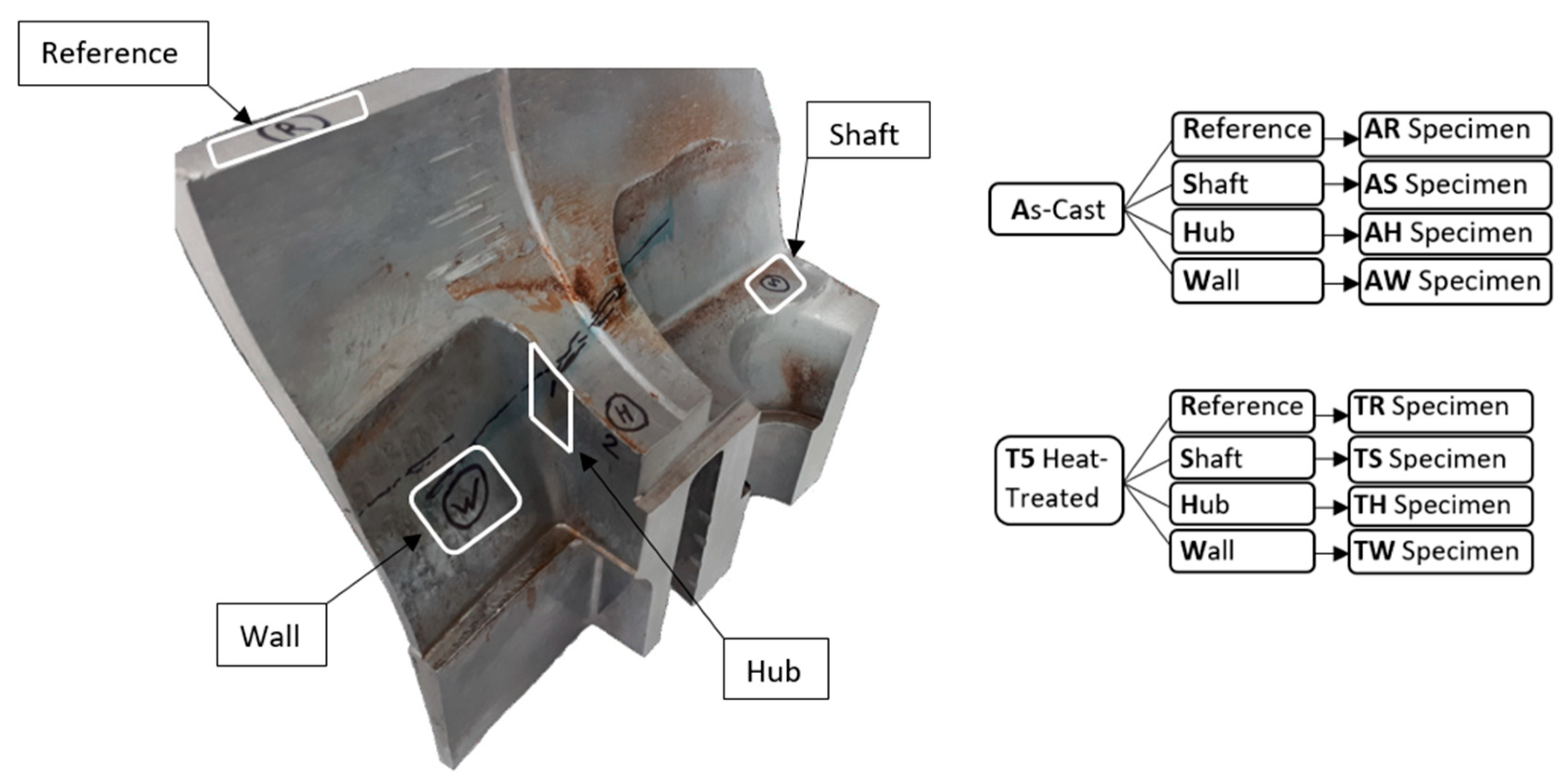
Figure 1.
Locations and naming scheme of the samples taken from the gearcase.
Figure 2.
Representative micrographs for the as-cast component: (A) AH location; (B) close-up image of the red box region in (A) showing various phases.
Figure 3.
Representative micrographs for the as-cast component: (A) AR location; (B) close-up image of the red box region in (A) showing various phases.
Figure 4.
Representative micrographs for the as-cast component: (A) AS location; (B) close-up image of the red box region in (A) showing various phases.
Figure 5.
Micrographs for the as-cast component showing: (A) AW location; (B) close-up of the red box region in (A) showing various phases.
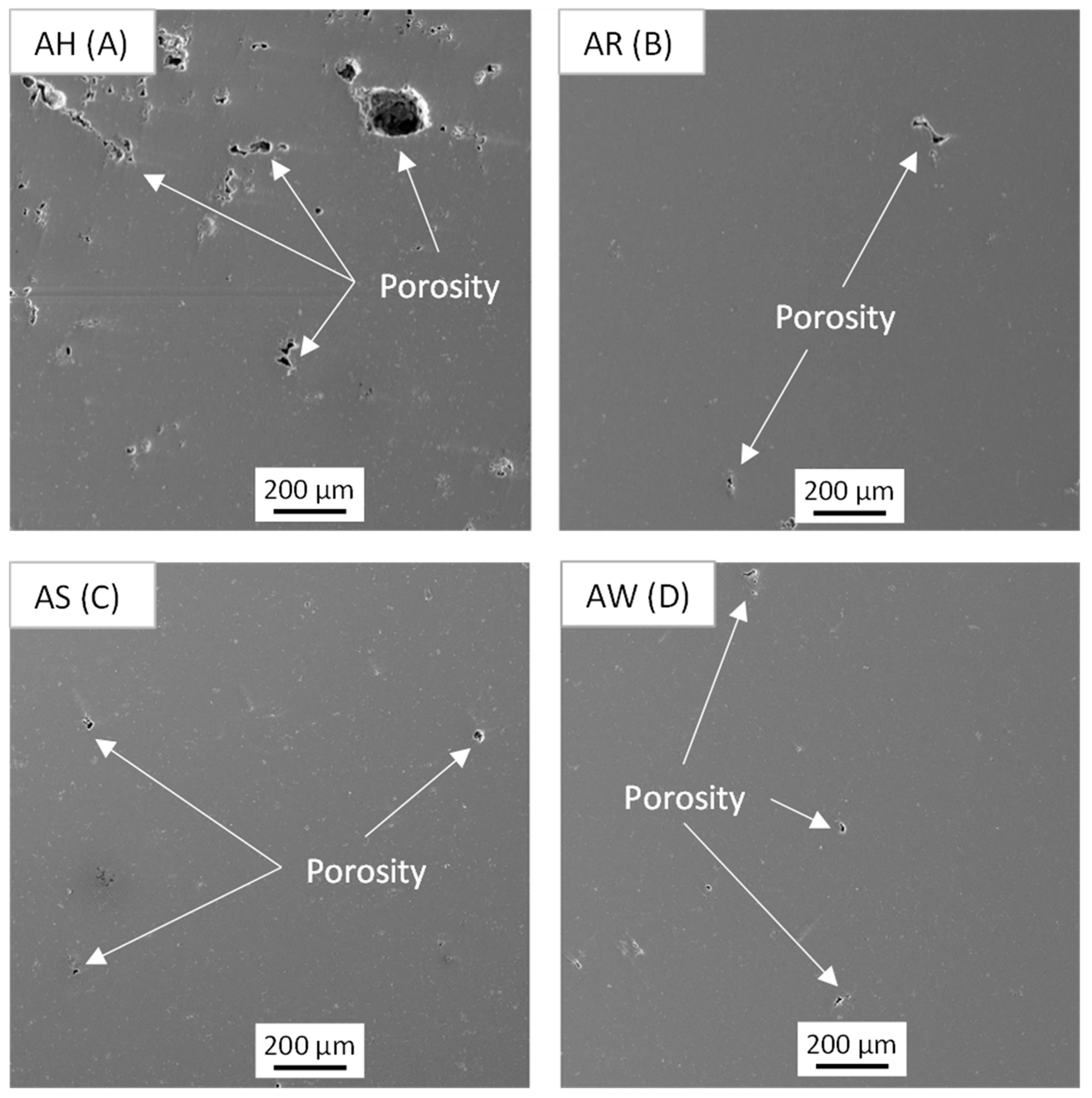
Figure 6.
Representative un-etched micrographs for various regions of the as-cast component showing the presence of porosities: (A) AH specimen; (B) AR specimen; (C) AS specimen; and (D) AW specimen.
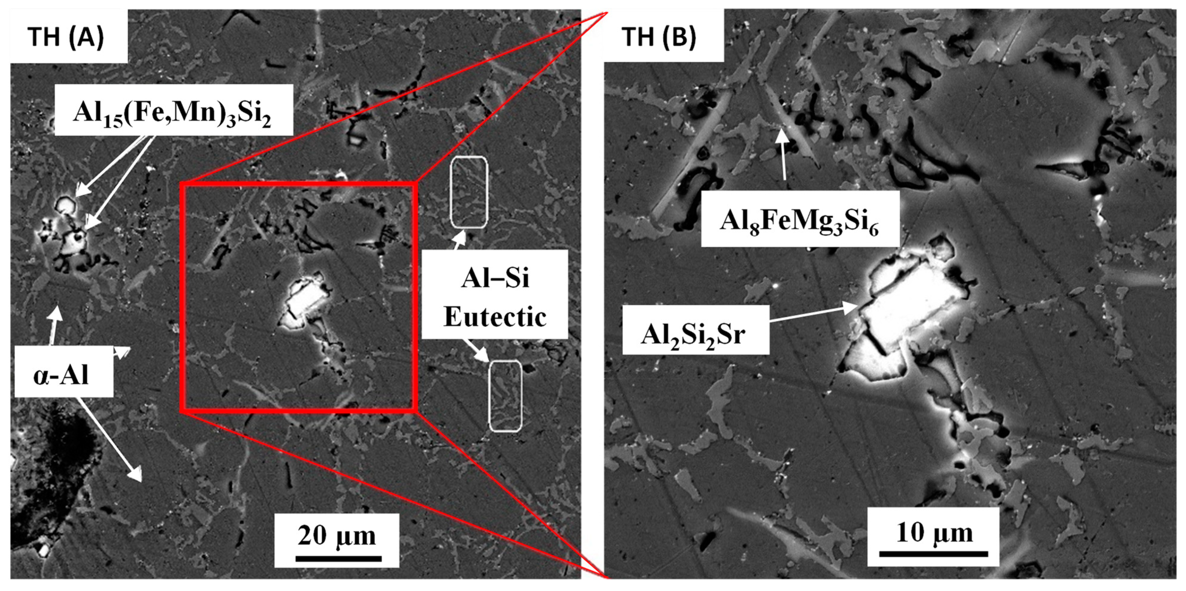
Figure 7.
Micrograph showing the TH specimen: (A) representative primary phases; (B) close-up of the red box region in (A).
Figure 8.
Micrograph showing the TR specimen: (A) representative primary phases; (B) close-up of the red box region in (A).
Figure 9.
Micrograph showing the TS specimen: (A) representative primary phases; (B) close-up of the red box region in (A).
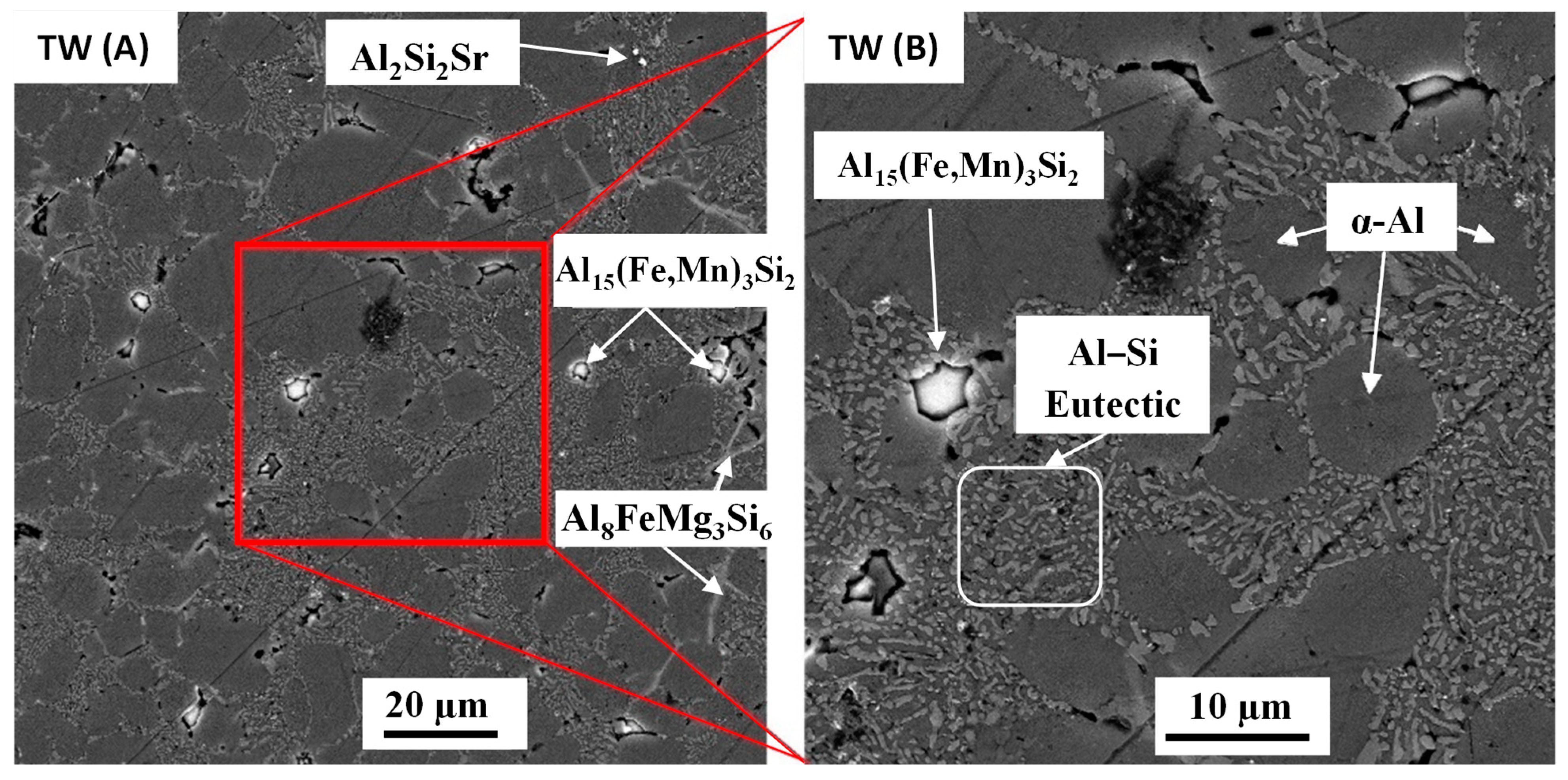
Figure 10.
Micrograph showing TW specimen: (A) representative primary phases; (B) close-up of the red box region in (A).
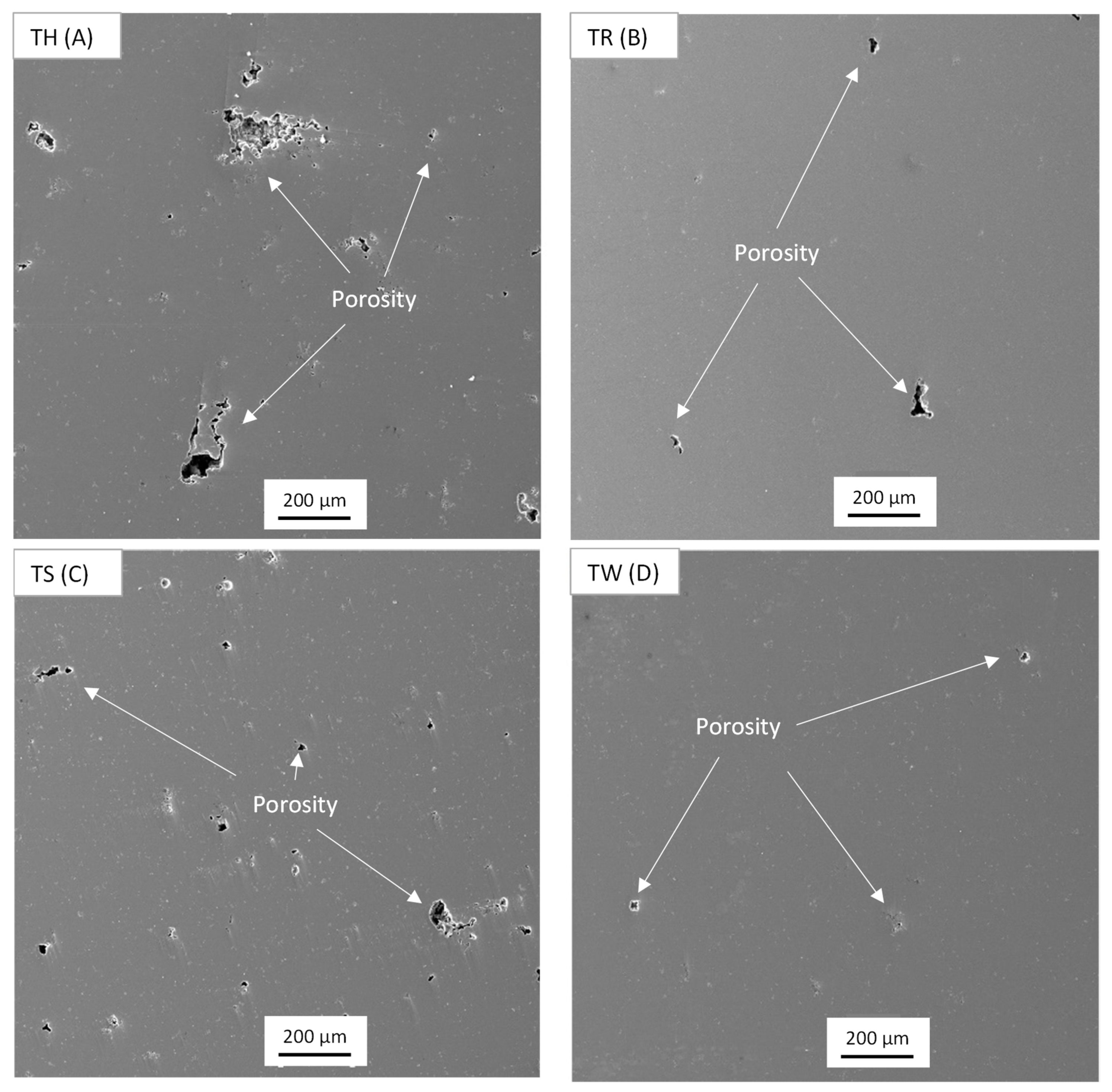
Figure 11.
Representative un-etched micrographs for various regions of the T5 component showing the presence of porosities: (A) TH specimen; (B) TR specimen; (C) TS specimen; and (D) TW specimen.
Figure 12.
SEM micrograph of TS showing the formation of porosity near the Al2Si2Sr phase.
Figure 13.
As-cast tensile test results.
Figure 14.
T5 heat-treated tensile test results.
Table 1.
The chemical composition (wt.%) of A362 alloy taken from the prototype gearcase.
| Sample | Si | Fe | Cu | Mn | Mg | Cr | Ni | Zn | Ti | Sr | Al |
|---|
| A362 Gearcase | 10.8 | 0.27 | 0.07 | 0.25 | 0.58 | 0.01 | 0.01 | 0.02 | 0.08 | 0.06 | Bal. |
Table 2.
Summary of the grain size, secondary dendrite arm spacing (SDAS) and cooling rate for the as-cast component.
| Measurement | AH | AR | AS | AW |
|---|
| SDAS ± SD (µm) | 18 ± 2 | 16 ± 2 | 16 ± 2 | 15 ± 3 |
| Cooling Rate (°C/s) | 7.8 | 11.7 | 11.8 | 14.1 |
Table 3.
Summary of the average volume fraction for various phases of interest in the as-cast component.
| Phases | As-Cast A362 Gearcase (Vol.% ± 95% C.I.) |
|---|
| AH | AR | AS | AW |
|---|
| α-Al | Bal. | Bal. | Bal. | Bal. |
| Al–Si eutectic | 53 ± 3 | 48 ± 3 | 48 ± 4 | 55 ± 4 |
| Al8FeMg3Si6 | 2.0 ± 0.5 | 2.3 ± 0.9 | 1.0 ± 0.2 | 3.0 ± 0.5 |
| Al15(Mn,Fe)3Si2 | 2.0 ± 0.5 | 1.5 ± 0.4 | 1.7 ± 0.2 | 2.3 ± 0.2 |
| Al2Si2Sr | 1.0 ± 0.3 | 1.5 ± 0.6 | 1.5 ± 0.5 | 1.3 ± 0.3 |
| Porosity | 1.9 ± 0.2 | 0.6 ± 0.1 | 0.9 ± 0.1 | 0.4 ± 0.1 |
Table 4.
Summary of the grain size, SDAS and cooling rate for the T5 heat-treated component.
| Measurement | TH | TR | TS | TW |
|---|
| SDAS ± SD (μm) | 17 ± 3 | 15 ± 4 | 16 ± 4 | 14 ± 4 |
| Cooling Rate (°C/s) | 9.2 | 12.5 | 11.1 | 17.3 |
Table 5.
Summary of the average volume fraction for the porosities and various phases of interest in the T5 heat-treated component.
| Phases | As-Cast A362 Alloy (Vol.% ± 95% C.I.) |
|---|
| TH | TR | TS | TW |
|---|
| α-Al | 43 ± 4 | 42 ± 3 | 46 ± 3 | 39 ± 2 |
| Al–Si eutectic | 47 ± 2 | 46 ± 3 | 43 ± 5 | 51 ± 3 |
| Al8FeMg3Si6 | 2.1 ± 0.4 | 1.9 ± 0.3 | 2.5 ± 0.6 | 3.6 ± 0.4 |
| Al15(Fe,Mn)3Si2 | 3.4 ± 0.6 | 2.3 ± 0.3 | 3.2 ± 0.4 | 3.4 ± 0.3 |
| Al2Si2Sr | 1.1 ± 0.2 | 0.9 ± 0.2 | 1.3 ± 0.2 | 1.4 ± 0.3 |
| Porosity | 1.6 ± 0.3 | 0.8 ± 0.2 | 1.3 ± 0.3 | 0.7 ± 0.2 |
Table 6.
Tensile test results for as-cast gearcase.
| Properties | AR | AS | AH |
|---|
| UTS (MPa) | 205 ± 10 | 178 ± 10 | 200 ± 10 |
| YS (MPa) | 167 ± 2 | - | 163 ± 2 |
| Young’s Modulus (GPa) | 72.4 ± 1.5 | 68.9 ± 1.5 | 69.6 ± 1.5 |
| Percent elongation (%) | 1.0 ± 0.2 | 0.4 ± 0.2 | 0.9 ± 0.2 |
Table 7.
Tensile test results for the T5 heat-treated gearcase.
| Properties | Reference | Shaft | Hub |
|---|
| UTS (MPa) | 220 ± 10 | 169 ± 10 | 200 ± 10 |
| YS (MPa) | 169 ± 2 | 161 ± 2 | 160 ± 2 |
| Young’s Modulus (GPa) | 71.1 ± 1.9 | 66.8 ± 1.9 | 73.4 ± 1.9 |
| Percent elongation (%) | 1.3 ± 0.3 | 0.5 ± 0.3 | 1.0 ± 0.3 |
| Publisher’s Note: MDPI stays neutral with regard to jurisdictional claims in published maps and institutional affiliations. |
© 2021 by the authors. Licensee MDPI, Basel, Switzerland. This article is an open access article distributed under the terms and conditions of the Creative Commons Attribution (CC BY) license (http://creativecommons.org/licenses/by/4.0/).


