
Experimental and Simulation Analysis of Effects of Laser Bending on Microstructures Applied to Advanced Metallic Alloys

 ,
,
Abstract
:1. Introduction
2. Materials and Methods
2.1. Materials
2.2. Laser Bending Experiment
2.3. Numerical Simulation
2.4. Microstructure Characterization
2.5. Stress Analysis
3. Results and Analysis
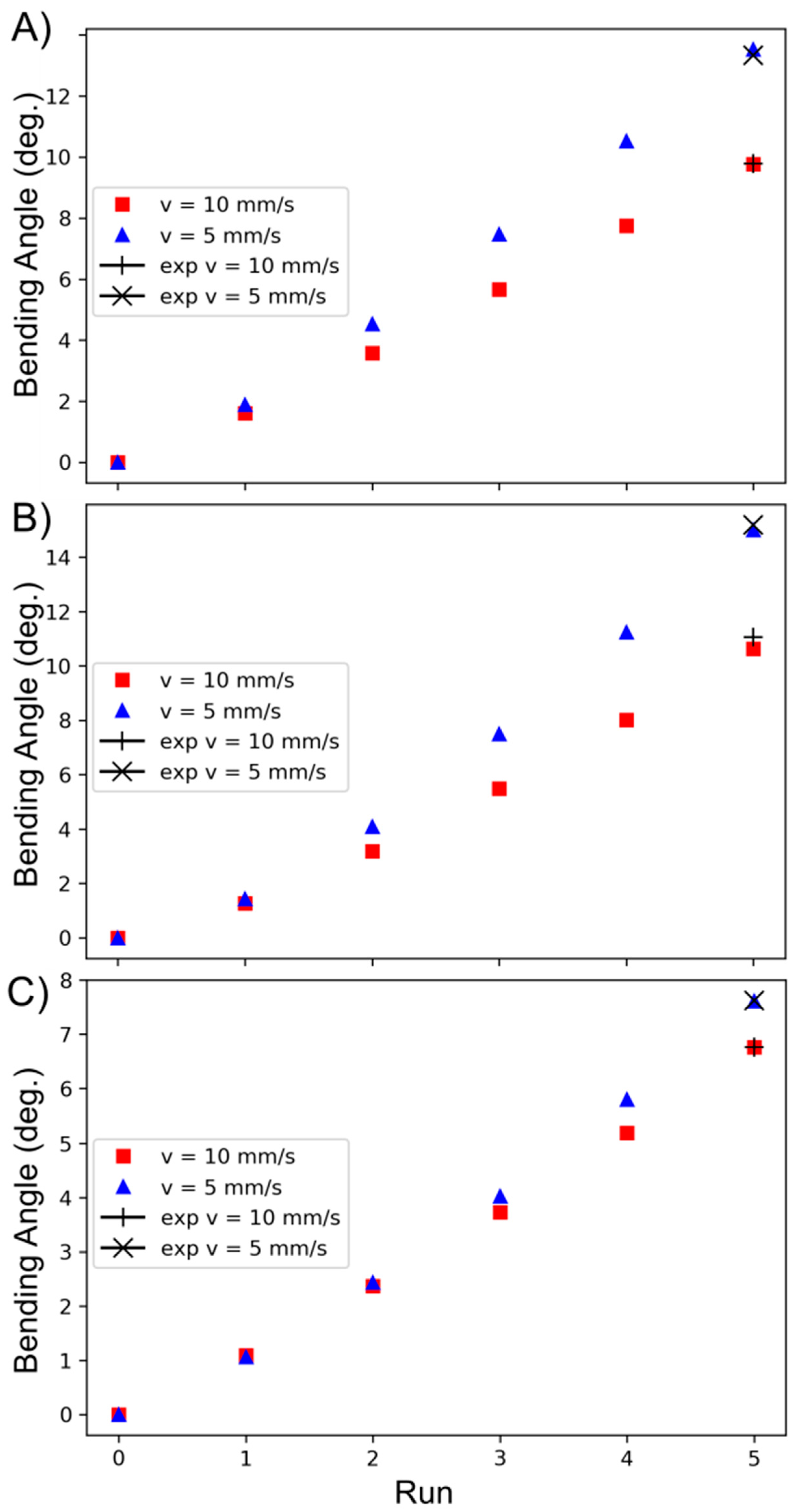
3.1. Laser Bending
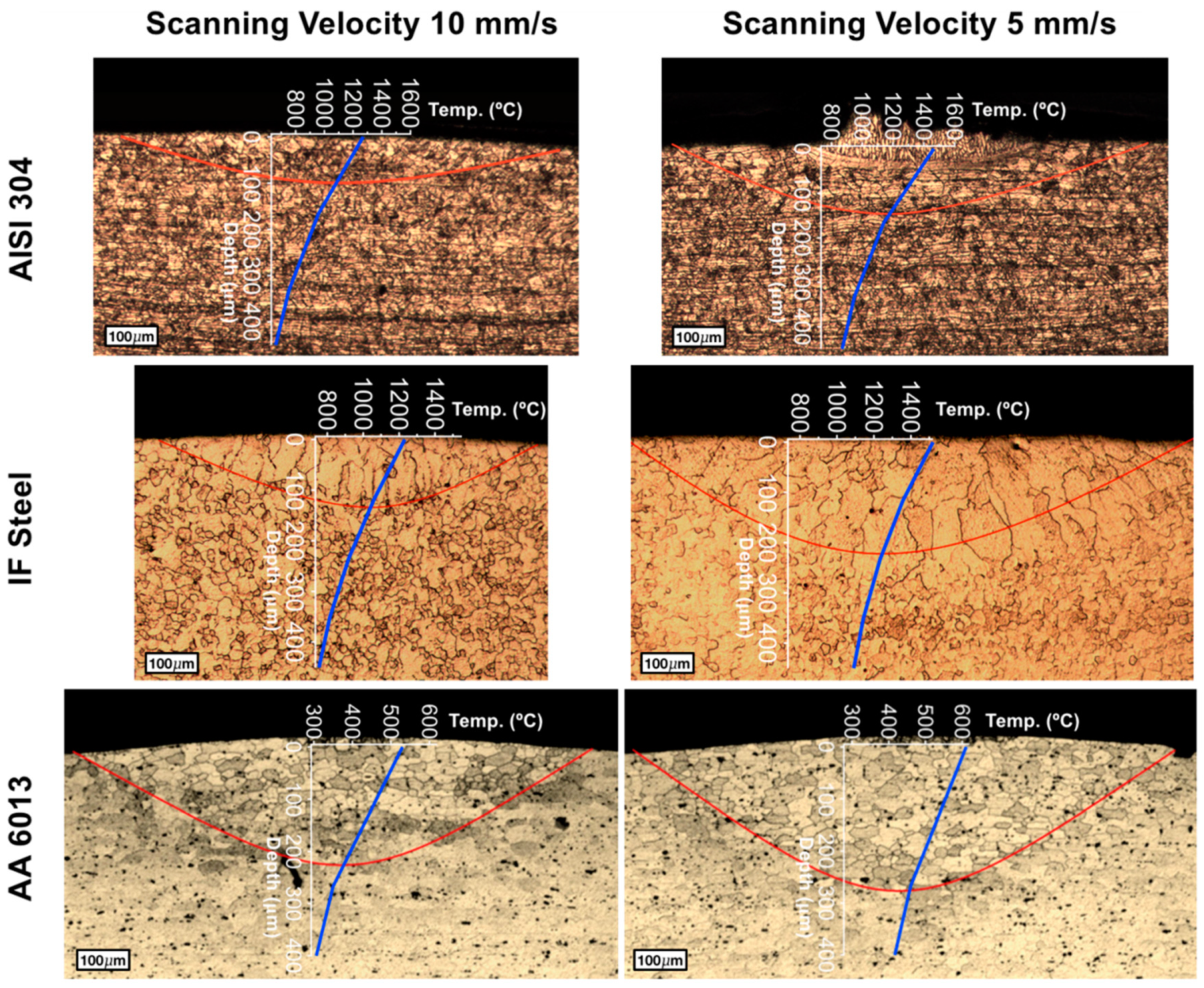
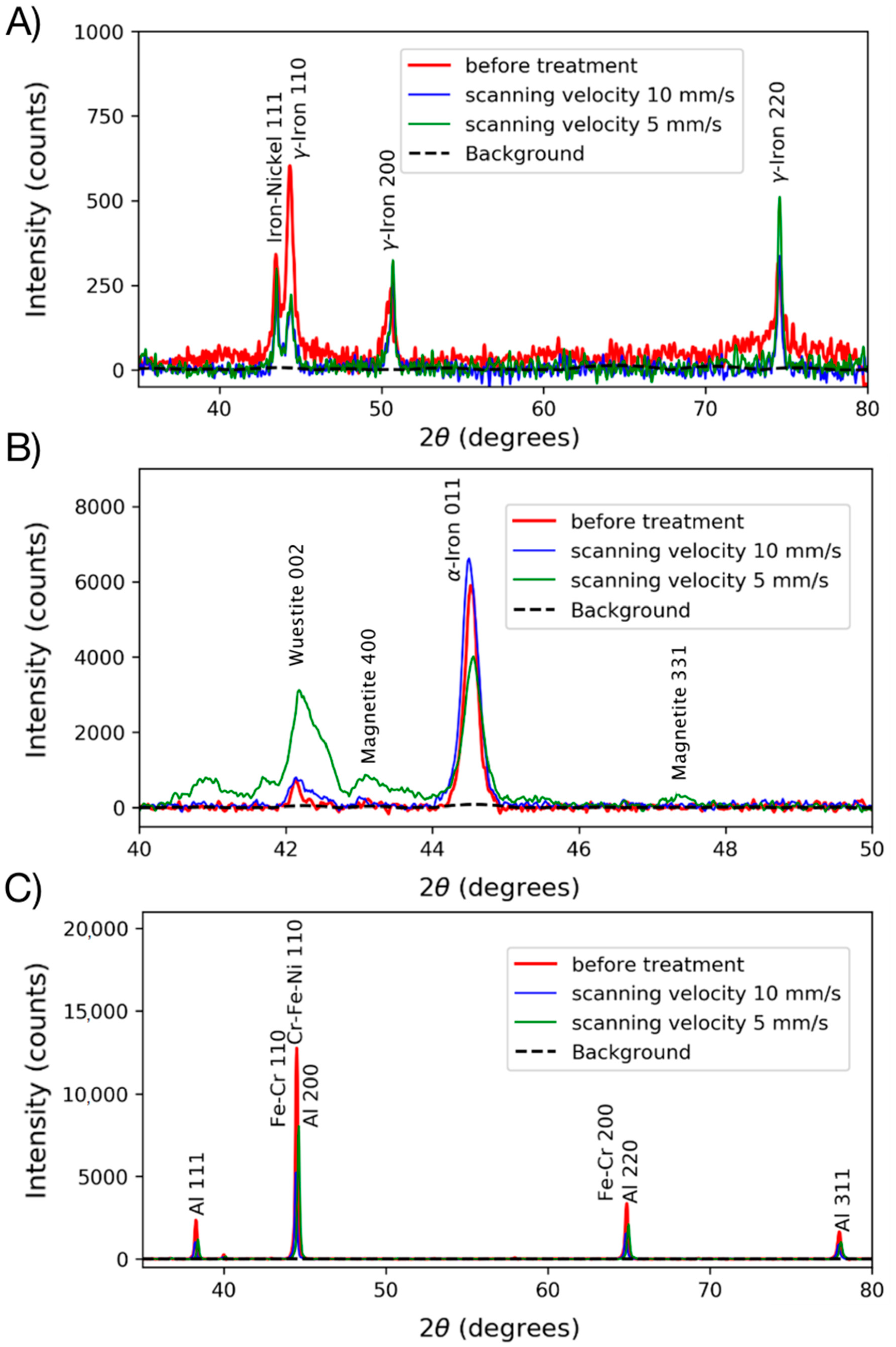
3.2. Microstructure
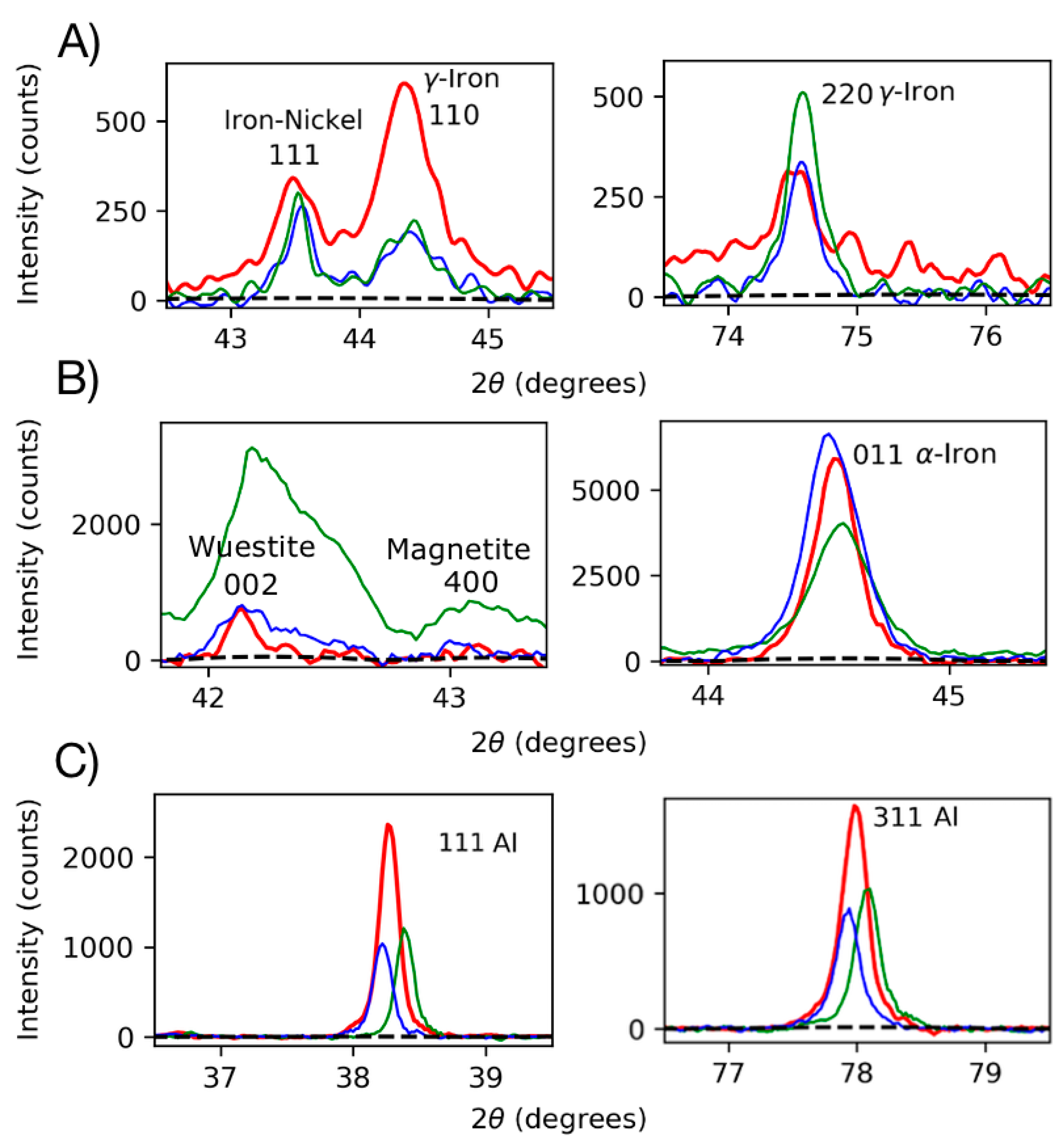
3.3. Stress Analysis
4. Discussion
5. Conclusions
- Bending angles due to the treatment were predicted and experimentally validated, and therefore the model can be applied to other advanced alloys;
- The treatment mainly induces grain growth and melting in the case of high surface temperatures;
- Before melting, the materials develop compressive microstresses that prevent cracking failure;
- Further modeling must include more microstructure effects, such as grain border diffusion and surface roughness.
Author Contributions
Funding
Data Availability Statement
Acknowledgments
Conflicts of Interest
References
- Magee, J.; Watkins, K.G.; Steen, W.M. Advances in laser forming. J. Laser Appl. 1998, 10, 235. [Google Scholar] [CrossRef]
- Maji, K.; Shukla, R.; Nath, A.; Pratihar, D. Finite Element Analysis and Experimental Investigations on Laser Bending of AISI304 Stainless Steel Sheet. Procedia Eng. 2013, 64, 528–535. [Google Scholar] [CrossRef] [Green Version]
- Navarrete, Á.; Cook, F.; Celentano, D.; Cruchaga, M.; García-Herrera, C. Numerical Simulation and Experimental Validation of Sheet Laser Forming Processes Using General Scanning Paths. Materials 2018, 11, 1262. [Google Scholar] [CrossRef] [Green Version]
- Cook, F.; Miró, L.; Celentano, D.; Ramos-Grez, J. Effect of inclination angle on the absorptance of a graphite-coated cold-rolled steel sheet irradiated by laser. J. Laser Appl. 2016, 28, 022001. [Google Scholar] [CrossRef]
- Safari, M.; Farzin, M.; Ghaei, A. Investigation into the effects of process parameters on bending angle in the laser bending of tailor machined blanks based on a statistical analysis. J. Laser Appl. 2013, 25, 052001. [Google Scholar] [CrossRef]
- Shen, H.; Vollertsen, F. Modelling of laser forming—An review. Comput. Mater. Sci. 2009, 46, 834–840. [Google Scholar] [CrossRef]
- Watkins, K.G.; Edwardson, S.P.; Magee, J.; Dearden, G.; French, P.; Cooke, R.L.; Sidhu, J.; Calder, N.J. Laser Forming of Aerospace Alloys; SAE Technical Paper; SAE International: Warrendale, PA, USA, 2001. [Google Scholar] [CrossRef]
- Safari, M.; Farzin, M. Experimental investigation of laser forming of a saddle shape with spiral irradiating scheme. Opt. Laser Technol. 2015, 66, 146–150. [Google Scholar] [CrossRef]
- Chakraborty, S.S.; More, H.; Nath, A.K. Laser forming of a bowl shaped surface with a stationary laser beam. Opt. Lasers Eng. 2016, 77, 126–136. [Google Scholar] [CrossRef]
- Cook, F.; Celentano, D.; Ramos-Grez, J. Experimental-numerical methodology for the manufacturing of cranial prosthesis via laser forming. Int. J. Adv. Manuf. Technol. 2016, 86, 2187–2196. [Google Scholar] [CrossRef]
- Tavakoli, A.; Naeini, H.M.; Roohi, A.H.; Gollo, M.H.; Shahabad, S.I. Codification of scan path parameters and development of perimeter scan strategies for 3D bowl-shaped laser forming. Opt. Laser Technol. 2018, 98, 121–133. [Google Scholar] [CrossRef]
- Navarrete, Á.; Celentano, D. Effect of workpiece geometry using circular scan patterns in sheet laser forming processes. Int. J. Adv. Manuf. Technol. 2018, 96, 1835–1846. [Google Scholar] [CrossRef]
- Gollo, M.H.; Mahdavian, S.; Naeini, H.M. Statistical analysis of parameter effects on bending angle in laser forming process by pulsed Nd:YAG laser. Opt. Laser Technol. 2011, 43, 475–482. [Google Scholar] [CrossRef]
- Safari, M. Numerical Investigation of the Effect of Process and Sheet Parameters on Bending Angle in the Laser Bending Process. World J. Mech. 2014, 4, 97–101. [Google Scholar] [CrossRef] [Green Version]
- Gautam, S.; Singh, S.; Dixit, U. Laser Forming of Mild Steel Sheets Using Different Surface Coatings. In Lasers Based Manufacturing; Springer: New Delhi, Indian, 2015; pp. 17–39. ISBN 978-81-322-2351-1. [Google Scholar]
- Stevens, V.; Celentano, D.; Ramos-Grez, J.; Walczak, M. Experimental and Numerical Analysis of Low Output Power Laser Bending of Thin Steel Sheets. J. Manuf. Sci. Eng. 2012, 134, 031010. [Google Scholar] [CrossRef]
- Castillo, J.I.; Celentano, D.J.; Cruchaga, M.A.; García-Herrera, C.M. Characterization of strain rate effects in sheet laser forming. Comptes Rendus Mécanique 2018, 346, 794–805. [Google Scholar] [CrossRef]
- Siqueira, R.H.M.; Carvalho, S.M.; Kam, I.K.L.; Riva, R.; Lima, M.S.F. Non-contact sheet forming using lasers applied to a high strength aluminum alloy. J. Mater. Res. Technol. 2016, 5, 275–281. [Google Scholar] [CrossRef]
- Costanza, G.; Tata, M.E. Mechanical behavior of Nd:YAG laser welded aluminum alloys. Procedia Struct. Integr. 2020, 28, 132–138. [Google Scholar] [CrossRef]
- Guan, Y.; Sun, S.; Zhao, G.; Luan, Y. Influence of material properties on the laser-forming process of sheet metals. J. Mater. Process. Technol. 2005, 167, 124–131. [Google Scholar] [CrossRef]
- Cook, F.; Jacobsen, V.; Celentano, D.; Ramos-Grez, J. Characterization of the absorptance of laser irradiated steel sheets. J. Laser Appl. 2015, 27, 032006. [Google Scholar] [CrossRef]
- Jablonka, A.; Harste, K.; Schwerdtfeger, K. Thermomechanical properties of iron and iron-carbon alloys: Density and thermal contraction. Steel Res. 1991, 62, 24–33. [Google Scholar] [CrossRef]
- Davey, W.P. Precision Measurements of the Lattice Constants of Twelve Common Metals. Phys. Rev. 1925, 25, 753–761. [Google Scholar] [CrossRef]
- Gražulis, S.; Daškevič, A.; Merkys, A.; Chateigner, D.; Lutterotti, L.; Quirós, M.; Serebryanaya, N.R.; Moeck, P.; Downs, R.T.; Le Bail, A. Crystallography Open Database (COD): An open-access collection of crystal structures and platform for world-wide collaboration. Nucleic Acids Res. 2011, 40, D420–D427. [Google Scholar] [CrossRef] [PubMed]
- Hauk, V.; Behnken, H. Structural and Residual Stress Analysis by Nondestructive Methods; Elsevier: Amsterdam, The Netherlands, 1997; ISBN 444824766. [Google Scholar]
- Sinha, M.; Karmakar, A.; Syed, B.; Ghosh, S. Effect of Austenite Conditioning on Martensitic Transformation in Commercial Grade Interstitial-Free Steel. Met. Mater. Trans. A 2020, 51, 3435–3446. [Google Scholar] [CrossRef]
- Suarez, S.; Ramos-Moore, E.; Mücklich, F. A high temperature X-ray diffraction study of the influence of MWCNTs on the thermal expansion of MWCNT/Ni composites. Carbon 2013, 51, 404–409. [Google Scholar] [CrossRef]
- Suarez, S.; Ramos-Moore, E.; Lechthaler, B.; Mücklich, F. Grain growth analysis of multiwalled carbon nanotube-reinforced bulk Ni composites. Carbon 2014, 70, 173–178. [Google Scholar] [CrossRef]
- Rollett, A.; Humphreys, F.; Rohrer, G.S.; Hatherly, M. Recrystallization and Related Annealing Phenomena, 2nd ed.; Elsevier: Amsterdam, The Netherlands, 2004; ISBN 9780080441641. [Google Scholar]


| Sample | Laser Power (W) | Scanning Velocity (mm/s) | Linear Energy (J/mm) | Final Linear Energy (J/mm) |
|---|---|---|---|---|
| AISI 304 | 100 | 10 | 10 | 50 |
| 5 | 20 | 100 | ||
| IF Steel | 100 | 10 | 10 | 50 |
| 5 | 20 | 100 | ||
| AA 6013 | 200 | 10 | 20 | 100 |
| 5 | 40 | 200 |
| Material | Source | Fe | Al | Mn | C | Ni | Cr | Cu | Si | P | Mg |
|---|---|---|---|---|---|---|---|---|---|---|---|
| AISI 304 | This work | Bal. | - | 3.1 | 0.03 | 8.6 | 15 | 0.4 | 0.4 | 0.3 | - |
| UNS S30400 | - | - | ≤2 | ≤0.08 | 8–10.5 | 18–20 | - | ≤1 | ≤0.045 | - | |
| IF Steel | This work | Bal. | 0.07 | 0.14 | 0.04 | 0.03 | 0.01 | 0.01 | - | - | - |
| VDA 239-100 | Bal | ≥0.01 | ≤1.6 | ≤0.01 | - | - | ≤0.2 | ≤0.3 | ≤0.1 | - | |
| AA 6013 | This work | 0.3 | Bal. | 0.4 | - | - | - | 0.8 | 0.5 | - | 0.8 |
| UNS A96013 | ≤0.5 | Bal. | 0.2–0.8 | - | - | ≤0.1 | 0.6–1.1 | 0.6–1 | - | 0.8–1.2 |
| Material | Front-Point Depth (μm) | Front-Point Temperature (°C) | Surface Temperature (°C) | Melting Temperature (°C) | |||
|---|---|---|---|---|---|---|---|
| Scanning Velocity | 10 mm/s | 5 mm/s | 10 mm/s | 5 mm/s | 10 mm/s | 5 mm/s | Solidus–Liquidus |
| AISI 304 | 82 | 153 | 1075 | 1158 | 1270 | 1465 | 1400–1450 |
| IF Steel | 121 | 224 | 1047 | 1275 | 1232 | 1520 | ~1540 |
| AA 6013 | 245 | 285 | 385 | 473 | 530 | 611 | 580–650 |
| Treatment Condition | Elastic Stresses (σ) | |
|---|---|---|
| AISI 304 | ||
| Scanning Velocity | 10 mm/s | 5 mm/s |
| σ(110 γ-Iron) | −90 MPa | 527 MPa |
| IF | ||
| Scanning Velocity | 10 mm/s | 5 mm/s |
| σ(011 α-Iron) | 190 MPa | −5 MPa |
| AA 6013 | ||
| Scanning Velocity | 10 mm/s | 5 mm/s |
| σ(311 Al) | 42 MPa | −63 MPa |
Publisher’s Note: MDPI stays neutral with regard to jurisdictional claims in published maps and institutional affiliations. |
© 2021 by the authors. Licensee MDPI, Basel, Switzerland. This article is an open access article distributed under the terms and conditions of the Creative Commons Attribution (CC BY) license (http://creativecommons.org/licenses/by/4.0/).
Share and Cite
Ramos-Moore, E.; Hoffmann, J.; Siqueira, R.H.M.; Medeiros de Carvalho, S.; Fernandes de Lima, M.S.; Celentano, D.J. Experimental and Simulation Analysis of Effects of Laser Bending on Microstructures Applied to Advanced Metallic Alloys. Metals 2021, 11, 362. https://doi.org/10.3390/met11020362
Ramos-Moore E, Hoffmann J, Siqueira RHM, Medeiros de Carvalho S, Fernandes de Lima MS, Celentano DJ. Experimental and Simulation Analysis of Effects of Laser Bending on Microstructures Applied to Advanced Metallic Alloys. Metals. 2021; 11(2):362. https://doi.org/10.3390/met11020362
Chicago/Turabian StyleRamos-Moore, Esteban, Joaquín Hoffmann, Rafael H. M. Siqueira, Sheila Medeiros de Carvalho, Milton S. Fernandes de Lima, and Diego J. Celentano. 2021. "Experimental and Simulation Analysis of Effects of Laser Bending on Microstructures Applied to Advanced Metallic Alloys" Metals 11, no. 2: 362. https://doi.org/10.3390/met11020362