Article

Comparative Multi-Modal, Multi-Scale Residual Stress Evaluation in SLM 3D-Printed Al-Si-Mg Alloy (RS-300) Parts

by
Eugene S. Statnik
1,*,
Fatih Uzun
2,
Svetlana A. Lipovskikh
1,
Yuliya V. Kan
1,
Sviatoslav I. Eleonsky
3,
Vladimir S. Pisarev
3,
Pavel A. Somov
1,
Alexey I. Salimon
1,
Yuliya V. Malakhova
4,
Aleksandr G. Seferyan
4,
Dmitry K. Ryabov
4 and
Alexander M. Korsunsky
2,1,*
1
HSM Lab, Center for Energy Science and Technology, Skoltech, 121205 Moscow, Russia
2
MBLEM, Department of Engineering Science, University of Oxford, Oxford OX1 3PJ, UK
3
Central Aero-Hydrodynamics Institute Named after Prof. N.E. Zhukovsky (TsAGI), 140180 Zhukovsky, Russia
4
Light Materials and Technologies Institute, UC RUSAL, 121096 Moscow, Russia
*
Authors to whom correspondence should be addressed.
Metals 2021, 11(12), 2064; https://doi.org/10.3390/met11122064
Submission received: 3 December 2021 / Revised: 14 December 2021 / Accepted: 16 December 2021 / Published: 20 December 2021

Abstract

:
SLM additive manufacturing has demonstrated great potential for aerospace applications when structural elements of individual design and/or complex shape need to be promptly supplied. 3D-printable AlSi10Mg (RS-300) alloy is widely used for the fabrication of different structures in the aerospace industry. The importance of the evaluation of residual stresses that arise as a result of the 3D-printing process’ complex thermal history is widely discussed in literature, but systematic assessment remains lacking for their magnitude, spatial distribution, and comparative analysis of different evaluation techniques. In this study, we report the results of a systematic study of residual stresses in 3D-printed double tower shaped samples using several approaches: the contour method, blind hole drilling laser speckle interferometry, X-ray diffraction, and Xe pFIB-DIC micro-ring-core milling analysis. We show that a high level of tensile and compressive residual stresses is inherited from SLM 3D-printing and retained for longer than 6 months. The stresses vary (from −80 to +180 MPa) over a significant proportion of the material yield stress (from −⅓ to ¾). All residual stress evaluation techniques considered returned comparable values of residual stresses, regardless of dramatically different dimensional scales, which ranged from millimeters for the contour method, laser speckle interferometry, and XRD down to small fractions of a mm (70 μm) for Xe pFIB-DIC ring-core drilling. The use of residual stress evaluation is discussed in the context of optimizing printing strategies to enhance mechanical performance and long-term durability.

1. Introduction

Selective Laser Melting (SLM) 3D-printing as a technology of rapid fabrication of net shape or near-net shape metal parts for various applications has matured in last 20 years and reached the stage of readiness for mass-production. In this context, issues of quality stability and service life management have become the principal focus of further development. This is especially important for 3D-printable Ti, Ni, and Al alloys that have recently began to see increasing use in the aerospace domain [1,2,3]. Fatigue fracture tolerance is known to be sensitive to microstructure variability and tensile residual stress (RS) that persist after various fabrication operations [4]. Gas turbine engine components made of Ti and Ni are susceptible to fatigue linked to flight-related thermal and mechanical cyclic loading, and to the higher frequency loading related to turbine rotation and blade vibration [5]. To pave the way for widespread adoption, 3D-printed parts made from these alloys must be carefully assessed in terms of fatigue durability with the same rigor as traditional materials [6].
SLM 3D-printable Al-Si-Mg alloy has been recently utilized for the fabrication of thermoregulation casing of a gamma-ray detectors used in satellite applications [7]. Heating-cooling cycles are typical for many outer-space structures and devices forming parts of satellite equipment that alternatively pass lit and shadowed zones. These thermal excursions cause cycles of expansion and contraction that may promote fatigue cracking in 3D-printed parts, especially when tensile residual stress (RS) is inherited after fabrication. Relaxation annealing or surface modification (shot peening or laser shock peening) are traditional approaches to controlling the residual stresses. Both techniques have some drawbacks: annealing may cause intolerable distortions that require subsequent machining that brings additional costs and new residual stresses in the surface layers, while surface modification may increase roughness and give rise to significant residual stresses in the non-treated core regions.
Repeated localized laser melting that leads to the fusion of metal powder particles followed by cooling are the fundamental physical mechanisms involved in SLM 3D-printing. The complexity of the thermal history of a certain material volume becomes apparent if many important phenomena are considered, e.g., the completeness of homogenization in the liquid phase, phase separation for alloys with a solid solution phase and the associated liquation and localized oversaturation of solid solutions, grain nucleation and growth from overcooled liquids. shrinkage at solidification, aging of solid solutions, and many others. High-temperature gradients and steep cooling rates during building provoke diverse structure formation and variation processes that ultimately give rise to non-uniform plastic deformation and the associated permanent inelastic strains (eigenstrains) that act as the origins of residual stresses [8].
The amount of literature and accompanying technical information devoted to additive manufacturing at large and laser printing with metals is vast and difficult to cover within a specific research paper (not a review article). Rational studies devoted to this topic seek to distil the key underlying relationships between processing conditions and sample shapes, with different degrees of success, e.g., [9,10,11,12,13] The present authors have made a number of contributions to this effort [9,10,11,12,13] that address different aspects of AM productivity, dependence on printing sequence and orientation, analysis of the microstructure, etc. The present study represents another step towards improving the reliability of analysis and interpretation.
The quantitative evaluation of residual stresses in SLM 3D-printed metallic materials has come into the focus of research interest since the first decade of the 21st century [14], which paved the way for new techniques based on X-ray scattering and various sectioning-based methods at the macro- to micro- to nano-scales. Currently, dozens of publications on this subject are published annually, including highly cited comprehensive overviews [15]. Steels of the stainless and maraging varieties, Ti-6Al-4V, and Ni alloys (Inconels and Invars) are leading in terms of the number of publications devoted to residual stresses in SLM 3D-printed metals. Nevertheless, a significant number of reports [16,17,18,19,20,21,22,23,24,25] have been published recently aiming to elucidate different aspects of residual stresses in SLM-printable Al-Si-Mg alloys.
To the best of the authors’ knowledge, the first article on residual stresses in a SLM 3D-printed aluminum alloy (AlSi10Mg) [16] was published in 2018, reporting the use of the X-ray diffraction method for experimental measurements. Tensile and compressive stresses as high as 100 MPa were found in 3D-printed thin ( t = 1.2 mm) sheet parts of complex curveted shape. Generally speaking, laboratory X-ray diffraction remains the dominant method for experimental evaluation of residual stresses due to its non-destructive nature, in spite of the numerous known disadvantages such as the shallow region of interaction and large lateral averaging area. Other non-destructive (e.g., precise external shape measurements by means of contact and contactless scanning) and destructive techniques (such as hole drilling) have been applied and reported. The interpreting and modeling of residual stresses commonly require various computational data processing approaches and computer simulations.
The FIB-DIC micro-ring-core drilling method is the extension of the hole drilling method towards the microscopic dimensional scale. The method has been a developing project since the middle of 2000s [26]. At present, this method gives unprecedented opportunities to correlate structural peculiarities and residual stresses and is clearly relevant for 3D-printed materials. The FIB-DIC micro-ring-core drilling method requires the use of relatively complex dual FIB-SEM microscopes and skilled operators, but the robustness of the measurements has already reached the pre-standardization stage [27]. There are very few reports of using the FIB ring-core drilling method to measure residual stresses in SLM 3D-printed materials [22] and no reports on SLM 3D-printed Al-alloys were found in the literature to date. One of the reasons is believed to be the scale factor; the correspondence of the drilled ring diameter and average grain size is very important for the FIB ring-core drilling method. In order to probe Type I stresses (equivalent to engineering scale residual stresses), the diameter of a ring must be set to several grain sizes, a condition that is hard to satisfy with the most popular Ga FIB-SEM microscopes for large and medium-size grains (20 μm and bigger) in materials such as Al-Si-Mg printable alloys.
Most recent published reports devoted to residual stresses in SLM 3D-printed Al-Si-Mg alloy components consider geometries that are either over-simplified (rectangular blocks) or overly complex, i.e., containing multiple features that are difficult to parameterize and draw firm conclusions from. In the present study, a simple “double tower” sample geometry was chosen that consists of a larger and a smaller block, representing a change in the horizontal cross-section causing a modification of the heat flow and introducing the possibility of local (residual) stress concentration.
Furthermore, previous studies have typically employed conventional experimental characterization techniques based on X-ray diffraction, the contour method, and mechanical blind hole drilling. These approaches have limitations in terms of achievable spatial resolution and their applicability to samples of complex shape. This is particularly worth emphasizing considering that the ease and economic viability of fabricating complicated shapes constitute a principal motivation for the use of 3D-printing.
The “double tower” prismatic sample shape is a good example of an “incremental” approach in the expansion of knowledge. This shape represents a step forward from a simple 3D prismatic element towards parts containing abrupt reductions of sample cross-section. Protruding shapes are commonly used in engineering design, especially in casings, guides and fitting parts, or actuators, making such objects relevant to practical engineering use.
The present authors recently studied the peculiarities of grain structure and mechanical performance of 3D-printed RS-333 Al-alloy parts [28,29] and considered the possible influence of the residual stresses on the variation of mechanical response. In the present article, we report a systematic comparative study of under-surface residual stresses in 3D-printed RS-300 series (AlSi10Mg) alloy samples using a number of macroscopic destructive techniques such as the contour method, hole drilling coupled with laser speckle interferometry, and microscopic Xe-ion pFIB-DIC ring-core drilling. Conventional X-ray diffraction ( sin 2 ψ ) measurements were also carried out to complete the multi-technique characterization study. This approach was purposefully and systematically implemented to highlight the fundamental hierarchical character of RS at scaling dimensional levels with the Xe-FIB-DIC microscopic method to investigate the details, which were not captured with methods at the macroscopic level. To the best of authors’ knowledge, this approach has not been systematically applied to the majority of SLM 3D-printed metals and especially not to Al alloys, where RS are relatively small.
It has been experimentally found that the high levels of tensile and compressive residual stresses inherited after SLM 3D–printing vary in the range from 40 to 200 MPa (i.e., up to the yield stress) and remain unrelaxed for at least 6 months. All evaluation techniques return comparable estimates of residual stress values, in spite of the dramatically different dimensional scales, from millimeters for the contour method and laser speckle interferometry down to 70 µm for Xe pFIB-DIC ring-core drilling. In the concluding part of the manuscript, the authors address the subject of how the tuning of printing parameters may offer an approach to rational residual stress management to enhance both mechanical performance and service lifetime.

2. Materials and Methods

2.1. Sample Manufacturing and Preparations

The double tower-shaped prismatic object shown in Figure 1 with its respective dimensions was purposely designed to incorporate an abrupt change in the cross-section and the corresponding temperature and stress gradient. Samples were printed under argon atmosphere using an EOS M290 SLM printer (EOS GmbH, Maisach, Germany) equipped with a 400 W Yb-fiber laser (IR irradiation with the wavelength of 1075 nm). Powdered RS-300 alloy (contains 9.75% Si, 0.22% Mg, 0.2% Fe) was produced via nitrogen atomization and supplied by Valcom-PM Ltd. (Volgograd, Russia). The scanning speed used was 1200 mm/s and hatch distance was 0.17 mm at the laser power of 370 W. Base plate temperature was 35 °C. The layer thickness was set to 30 µm. “Core” parameters were applied to the whole sample without any additional treatment of contours and surfaces. The 10 mm thick support base (filling ratio 50%) was mechanically cut. No post-printing heat treatment (aging) was applied to release residual stress. The sample was shelved for 6 months in ambient conditions and dry atmosphere before any further manipulations.
A special casing was machined from a piece of hardened aluminum alloy D16 (Russian designation of AA2024) to ensure tight fixation of the double tower specimen during EDM cutting using a Mitsubishi MV-1200R machine (Mitsubishi Electric Europe B.V., Ratingen, Germany), which was performed with the slowest cutting speed. This casing is shown in Figure 2. The two halves of the specimens were then studied with a number of approaches: the contour method, macroscopic hole drilling with laser speckle interferometry, X-ray diffraction, and Xe pFIB-DIC micro-ring-core drilling. Each of these methods is capable of evaluating the in-plane residual stresses that persist at the surface of the cut plane(s).

2.2. Contour Method

Optical 3D scanner RangeVision PRO Base (RangeVision Ltd., Moscow, Russia) was used to acquire volumetric profilometry data (surface point positions). This procedure was used to generate a digital geometry image (digital twin) of the double tower sample as a cloud of points before and after EDM cutting along the red line shown in Figure 2b. The scanner parameters were the following: working distance 260 mm, 3D resolution 0.05 mm, scanning resolution 18 µm. 3D models before and after EDM cutting are shown in Figure 3.
FEniCS, an open-source (LGPLv3) computing platform for solving partial differential equations (PDEs), was used to formulate and solve the continuum mechanics problem using the refined set of scanned digital data (cloud of points) as a reconstruction of the “true” surface geometry. The current paper represents the first use of FEniCS to effect the contour method reconstruction of residual stresses that was carried out at the Multi-Beam Laboratory for Engineering Microscopy (MBLEM). The experimental data was processed using the method described in the previous study by the authors of [30] for the determination of out-of-plane surface displacements as a result of stress relaxation induced by non-disturbing EDM sectioning. Following the contour method approach, the reverse of surface displacements was assigned as the displacement boundary conditions of the numerical model geometry on the surface that corresponds to the EDM cut.
It is important to point out at this stage that the contour method was developed and validated for the calculation of residual stresses in continuously processed bodies [31]. However, the sample geometry considered in the present study had the 3D shape of a “double tower” composed of larger and smaller area segments. This property of the part, along with the complexity of the SLM 3D printing process, means that the situation no longer corresponds to the continuously processed body assumption. Nevertheless, a numerical model was developed and applied that uses real geometry to reconstruct the residual stresses within the sectioned half of the sample. Partial validation of the approach was sought by comparison with local residual stress evaluation using FIB-DIC micro-ring-core milling method [32]. For the purpose of comparison, another numerical model was used for a continuously processed (plane strain) body of extrusion for both larger and smaller area segments.

2.3. Hole Drilling and Laser Speckle Interferometry Method

The hole-drilling method is a destructive technique that measures local deformations in the vicinity of a drilled hole (increment or decrement of hole diameter). Drilling removes a certain amount of stressed material and, as a result, causes elastic strain redistribution of the typical order of magnitude ~10−3. Holes a few millimeters in diameter generate displacements of several micrometers that can be measured with sufficient accuracy. Electronic laser speckle-pattern interferometry technique applied for this purpose visualizes the interference fringe patterns generated by in-plane displacements. The corresponding interferograms were recorded by two symmetrical side detectors (digital cameras) when a diode laser of wavelength 532 nm was directed at the surface containing the drilled hole. The phase shift between the two surface states before and after drilling forms alternating dark and light interference patterns known as fringes. Typical interference fringe patterns used for residual stress determination at the point of drilling are shown in Figure 4. The number of fringes is linearly related with the diameter increment or decrement. These quantities are related by the multiplication factor λ 2 sin θ , where λ is the incident illumination light wavelength and 2 θ is the angle between the incident and reflected beams [33]. Drilling was conducted on the cut plane as well as on the outer faces of the cut-in-half double tower specimens using a drill bit diameter of from 1.9 to 2.5 mm. The drilling depth was set equal to the drill bit diameter. The values of the hole diameter increment in the principal stress directions were used as the initial experimental information for further calculation of the principal residual stress components. The typical uncertainty inherent in the determination of the maximum in-plane principal residual stress component is in the order of 5%. The approach is thought to be valid for residual stress values that do not exceed 60% of the material yield stress.

2.4. X-ray Diffraction Method

The X-ray diffraction method of residual stress evaluation commonly known as the sin 2 ψ method is widely applied and reported in the literature. Laboratory X-ray sources with Cu cathodes generate ~8 keV characteristic radiation that probes the shallow subsurface layers to the maximum depth of ~20 μm for Al alloys. In this situation, the surface roughness issue becomes critical, as in the case of SLM 3D-printed parts without post-printing surface treatment. The typical peak-to-trough measure of roughness is believed to be comparable with the average size of the powder particles, i.e., 20 μm [28]. Therefore, the cut plane of a half of the double tower samples was ground using a sequence of sandpapers in several steps corresponding to 220, 500, 1000, 2000, and 4000 grit, respectively. This was followed by polishing using diamond suspensions with an average particle diameter 1–3 µm, and finished with colloidal silica with an average particle diameter of 60 nm. The appearance of the cut surface after grinding and polishing is illustrated in Figure 5a. It should be noted that surface finishing by grinding and polishing may cause the re-distributing of existing residual stresses and may introduce new ones in the near-surface layers. However, provided good practice procedures are followed, the estimate for the thickness of the affected sub-surface layer corresponds to a few (typically, three) diameters of the final finishing silica particles [34]. This is much shallower than the penetration depth of Cu irradiation, so the values of residual stress obtained with the help of X-ray diffraction can be taken as a relevant measure of the pre-existing state of the samples.
A Bruker D8 Advance (Bruker AXS Inc., Madison, WI, USA) diffractometer equipped with a Cu cathode tube ( K α wavelength of 0.154 nm) in the line collimation mode was used in combination with a special tailor-made goniometer-like sample cradle that allowed omega-tilting mode for sin 2 ψ analysis. The cradle was designed and made in-house out of polylactide polymer (PLA) by FFF 3D-printing using a conventional FDM printer and PLA filament, facilitating ω (iso) and φ (side) tilting to reach φ values up to 60° with 10° steps. This holder is shown in Figure 5b. Digital X-ray diffraction spectra were processed using a conventional procedure that included fitting and subtracting the background, the stripping of K β peaks, approximation of the peak profile with a Gaussian function, calculation of d H K L from the 2 θ position of the peak center, and finally, the least squares fitting of the ε = ( d H K L d H K L 0 1 ) vs sin 2 ψ dependence with a linear function and the determination of the residual stress component from the fitted slope s using the X-ray Elastic Constant (XEC) of the material using
σ i s o = XEC × s = E ( 1 + ν ) × d ε h k l d ( sin 2 ψ )

2.5. Xe pFIB-DIC Micro-Ring-Core Drilling Method

The semi-destructive method known as FIB-DIC micro-ring-core drilling monitors the evolving strains at the top surface of the cylindrical core during ion etching of a ring-shaped trench in a FIB-SEM system. The strains are evaluated by means of digital image correlation algorithms capable of detecting displacements of pixel clusters with subpixel accuracy. Datasets of high-resolution images are accumulated by collecting good quality SEM images after each step of serial ion milling. As a rule, the full depth of the ring trench drilled with ions lies in the range of 1–2 core diameters in order to guarantee the complete relaxation of residual stresses in the core zone. The value of the complete relief strain is used to calculate the residual stresses present at the ring-core location prior to drilling. The FIB-DIC micro-ring-core method is sensitive to a number of factors that must be considered to ensure robust residual stress evaluation [26]. Optimal density of surface features must persist at the top surface during ion ring milling without being adversely affected by the re-deposition processes or by etching by divergent ion beams.
Xe plasma FIB has been less frequently used for residual stress analysis [35] compared to the conventional Ga FIB. A significant reason for the lower usage of Xe pFIB-SEM instruments for residual stress measurements concerns the higher cost of Xe pFIB-SEM microscopes in terms of purchase, maintenance, and consumables. On the other hand, the higher plasma FIB milling currents offers the opportunity to drill larger rings with typical diameters in the range from 20 to 100 μm in reasonable time. This offers the possibility of filling the spatial resolution gap between the Ga FIB-DIC method (from 1 to 20 μm) and mechanical drilling (from 500 to 3000 μm). It is the authors’ opinion, substantiated with the results presented below, that the technical difficulties related to material re-deposition can be overcome through careful optimization of milling parameters.
The present study made use of Xe pFIB-DIC micro-ring-core drilling to match the large average grain size in the material (>20 μm) to fulfil the requirement of the core diameter including many or at least several grains [34]. A Tescan Clara SEM equipped with an Oxford Instruments NordlysNano EBSD detector was used to visualize the grain microstructure using 20 kV, 30 nA beam settings. The area of 500 × 500 µm2 was scanned using a 1024 × 1024 pixel matrix, corresponding to the scanning step of 0.5 µm.
Xe pFIB FEG-SEM Helios 5 microscope (FEI, Thermo Fisher Scientific Inc, Agawam, MA, USA) was used for pFIB-DIC ring-core drilling and synchronized SEM visualization using an SE detector of the surface topography at the FEG acceleration voltage of 5 kV and an electron beam current of 3.2 nA. Optimal voltage and current parameters of ion milling were empirically adjusted through trial-and-error to the optimal setting of 30 kV voltage and 200 nA ion current. The tilt stage angle of 52° was used, with the ring-core diameter of 70 µm and the outer diameter of 100 µm. Datasets of 38 images per milling were collected, with the first 30 images corresponding to the step of 2 µm and the final 7 images taken with the step of 6 µm, yielding the overall milling depth of ~100 µm.
The quality of the EDM-sectioned plane provided a good density of irregular surface features. However, increased surface roughness impedes uniform ion drilling and synchronous SEM imaging due to the low visibility of the ring milling features at the 52° stage tilt required for ion milling, due to the high surface asperities caused by EDM cutting. On the other hand, sufficient density of contrasting surface features within the ring-core were found after silica finishing and thus provided satisfactory contrast for robust DIC analysis, which was therefore used for pFIB-DIC evaluation. Open-source MATLAB-based software iStress [36] was applied to evaluate the strain values in the range from 10−4 to 10−2 using image datasets of up to 60 images for the ring-core diameters of 70 μm.

3. Results and Discussion

3.1. Residual Stress Evaluation by the Contour Method

Calculations of the linear elastic numerical model were performed by setting Young’s modulus and Poisson’s ratio to the values of 67 GPa and 0.33, respectively, in accordance with the values determined by mechanical testing of the 3D-printed Al alloy samples.
The conventional formulation of the contour method [37] assumes that the object being considered satisfies the assumptions for the so-called continuously processed body. To rationalize these assumptions based on a firm theoretical footing it is best to state that the object finds itself in the state of plane eigenstrain. This means that the permanent inelastic strains that act as the sources of residual stress are distributed within a prismatic body of extrusion as a function of the transverse coordinates only. As a consequence, each transverse cross-section of the body finds itself in an identical state of residual stress. This, in turn, can be recovered by performing minimally disturbing planar cuts, e.g., using Electric Discharge Machining (EDM) of metallic alloy components, in order to map the out-of-plane displacements (deplanation) and apply them to a numerical model as a boundary condition with the opposite sign to re-create the out-of-plane stress distribution as a contour map. Although some theoretical and practical limitations of this approach can be identified, the method has been shown to be successful and was validated by comparison with independent measurements, e.g., by neutron diffraction [38]. Another important aspect of the contour method concerns the reconstruction of in-plane stress components: although this consideration is not included in the original formulation by Prime [38], attempts have been made subsequently to address this important matter, e.g., by Uzun et al. using the eigenstrain approach [30]. In the discussion below, the conventional contour method treatment based on the continuously processed body (plane eigenstrain) assumption is compared and contrasted with the use of the real component geometry for residual stress reconstruction.
Figure 6a,c show the z-component of residual stresses obtained for the real and continuously processed geometry models, respectively, calculated using the displacements defined as boundary conditions on the EDM-cut front face of the model located at the positive z side. The displacements induced in the body are illustrated in Figure 6b,d. On the other hand, residual stresses vanish with increasing depth along the z-axis in the main body in a way characteristic of the contour method [31]. The calculations that belong to the main body are consistent with the continuously processed body assumption. The stress magnitudes within the smaller area segment in the real and continuously processed body model geometries show high discrepancy, while similar distributions are observed in the larger area segments. The discussion and understanding of the mathematical implications of this difference lie outside the scope of the present study and will be examined separately.
Although the numerical model calculates all normal and shear components of residual stress in the whole body, only the z-component of the results for the “cut double tower” model geometry is reliable on the front face of the bottom segment. The results that belong to the upper segment and other components of the stress are thought to be less reliable, but may represent a good predictive approximation. Figure 7 illustrates x- and y-components of direct residual stress at the examined cut surface. Figure 8 shows all components of residual stress along the lines illustrated in Figure 7. The results show that the calculations of the contour method solution provide a good match with FIB-DIC evaluations of the x-component of residual stress in both real and continuous geometry models, but the quantity and quality of experimental measurements should be increased in order to state that all direct components of residual stress can be calculated reliably using the present approach. In addition, the comparison between the line plots of the real and continuous geometry models shows that residual stresses in the real geometry model lie within the elastic region, while they extend far beyond the yield strength of the material in the continuous geometry model. Accordingly, it can be stated that the real and continuous geometry models provide similar distributions in the large section of the model that satisfies the requirements of continuous processing, while they show disagreement in the small area section.
The contour method depends on the elastic response of the material subsequent to non-disturbing EDM sectioning. This relationship allows reconstructing the out-of-plane residual stress component within the section corresponding to the state of the component before sectioning. On the other hand, the x-component of residual stress evaluated using Xe-pFIB micro-ring-core milling technique belongs to the sectioned surface. On this surface, the out-of-plane component of residual stress is completely relaxed, while the x- and y-components of residual stress obtained from the contour method correspond to the pre-sectioning state. It is worth noting that according to Lunt et al. [39], sectioning involves a relief of in-plane residual stresses proportionally to ( 1 ν 2 ) , where ν is Poisson’s ratio. Based on the outputs of that study, it can be stated that the effect of sectioning on the Xe-pFIB residual stress evaluation corresponds to ~10% modification.
The relatively high cooling rate in the top-of-tower and bottom-of-basement locations suggests that fast thermal contraction in respect to the middle regions is balanced by tensile residual stresses. This provides a well-founded explanation for the mechanical response of dog-bone samples SLM 3D-printed in different orientations under tension and the beneficial effect of sand-blasting described in [29]. Specifically, the sample oriented identically to the bottom of the base of the double tower specimen was found to possess the lowest strength. This is likely to be linked to the inherited tensile residual stresses, but it is dramatically improved in terms of ductility after sand-blasting, which is known to introduce compressive residual stresses [40].
The middle part of the SLM 3D-printed sample is relatively thermally insulated; thus, it cools and shrinks last and, being thermally expanded because of this, inherits compressive residual stresses. Vertical outer surfaces of the heavy basement adjacent to the cut plane seem to be weakly stressed (small tensile or zero residual stresses), perhaps because of relatively slow cooling due to the significant thermal mass of the basement, contrary to the case of tower, where the temperature gradient is sharp enough to cause intensive heat flow (perhaps even from the basement), fast cooling, and large tensile residual stresses. This observation, while quite trivial and obvious, is nevertheless of great practical importance, suggesting that slim cross-sections and protruding elements should be repetitively printed at slower scanning speeds to retain high temperatures as long as possible. Annealing or shot peening post-processing treatments are recommended to be deliberately focused on these locations.

3.2. Residual Stress Evolution by Hole Drilling and Laser Speckle Interferometry Method

EDM cutting of the double tower specimen causes the residual stresses to be redistributed and relieved. Nevertheless, as discussed above, this effect is relatively moderate in magnitude (in the order of 10%) and takes place primarily in the vicinity of the cut.
Figure 9 demonstrates the locations of the probing holes, with the diameter of Point 1 equal to 2.5 mm, and all other points having diameters of 1.9 mm. The axes are designated at each probed face, with examples of interferograms with fringes shown for Point 1. Table 1 summarizes the estimations of residual stresses at six locations where fringes were reliable detected. Four of the drilled holes revealed no fringes, indicating low magnitude of residual stresses at the probed locations.
Unfortunately, the size of samples was not appropriate for drilling numerous holes, as would have been desirable to collect further data for accurate mapping with satisfactory spatial resolution.
Despite the fact that out-of-plane residual stresses (evaluated in the contour method) are not and should not be equivalent to in-plane residual stresses in the same locations, we must notice that the middle of the basement (Points 5 and 7) is stressed in compression. This observation fully corresponds to the findings of the contour method for out-of-plane residual stresses in the same locations. We suggest that the middle of the basement is hydrostatically compressed by residual stresses due to the late cooling (and thermal expansion) balanced by compression. On the contrary, the outer faces are residually stressed in tension, as discussed above.
The components of residual stresses perpendicular to the cut plane (and parallel to the out-of-plane residual stresses measured by the contour method) on the faces adjacent to the cut plane—points 3 and 9—are, however, relatively small (from −17 to +11 MPa), both for vertical and horizontal bottom-of-basement faces, perhaps due to the relaxation caused by EDM cutting. The vertical outer face parallel to the cut plane and far from cut plane-points 1, 2, and 10 reveals strong tensile residual stress, the values of which, along horizontal axis (from 118 to 128 MPa), are close to one third of the yield strength of this alloy after SLM 3D-printing, that is, in the range of from 280 to 350 MPa [41]. Residual stresses along the vertical axis are at least three times smaller, suggesting uneven cooling along this face.

3.3. Residual Stress Evolution by X-ray Diffraction Method

The roughness R a = 1.9 µm and R z = 11.2 µm were measured by the optical profilometer of the NanoScan-4D system (TISNCM, Troitsk, Russia) at the outer surface of double-tower as-printed. The penetration depth of Cu- K α irradiation (ca. 20 μ m) is comparable to roughness and, therefore, the measurements are not representative. X-ray diffraction ( sin 2 ψ ) method shows modest compressive residual stresses (from −300 to −350 MPa) in the polished cut plane, as shown in Figure 10. On the other hand, it is clearly seen in Figure 11 that few coarse scratches are still present somewhat affecting the results. This method measures in-plane residual stresses only and, as is also very important, assumes that all grain subsets (and all grain in a subset) diffracting at different φ angles are evenly and equally stressed as those grain subsets having ( H K L ) planes perpendicular to the cut plane ( sin 2 φ = 1). Averaging over the lighted area (from a few tens to a few hundreds of mm2 typical for laboratory X-rays) in the middle of cut plane gives no spatial resolution, which potentially can be improved with dedicated setups utilizing fine focus tubes and advanced sample positioning systems. We consider these results as elective.

3.4. Residual Stress Evolution by Xe pFIB Ring-Core Drilling Method

Robust application of the FIB-DIC method of RS evaluation requires the presence of a sufficient number of irregular surface features to allow tracking of small displacements (down to sub-pixel) caused by the strain relief during plasma or Ga ion milling of micro-ring-cores. In view of this, a balanced approach can be taken to surface polishing, in that the quality must be sufficient for reliable EBSD indexation but does not need to be any better. Figure 11 depicts the typical appearance of ion-drilled ring-core holes at the rough and polished surfaces of the cut plane at different half-cut double tower specimens with the corresponding dependence of relief strain over depth. It is clearly shown that the quality of surface polishing allowed collecting good EBSD maps to reveal the dimensional ratio between the grain size and ring-core diameter. For instance, it is apparent in Figure 11a that the core contains parts of many grains to achieve good averaging between grain orientations for the purpose of estimating Type I RS for engineering purposes that is comparable with the values returned by other methods. Furthermore, the application is presented as the result of a scratch-eliminating procedure as described and shown in Appendix A. Figure 12 maps residual stresses along the x axis at six points on the polished cut plane, and the values of evaluated in-plane residual stresses are in satisfactory agreement with the results obtained for out-of-plane residual stresses (contour method). The stress profile along line H1-H2-H3 corresponds to the change of residual stresses from strong tensile (exceeding yield strength level) at the top of the tower to modest compressive (about ⅓ of yield strength). The stress profile along line H5-H3-H4 demonstrates weak tensile residual stresses close to the vertical faces and somewhat stronger compressive residual stresses in the middle of the cut plane. All determined residual stresses are summarized in Table 2.The Xe-pFIB ring-core drilling method returns the estimation of residual stresses in location H6, which contradicts the contour method and requires further deeper investigations. Taking into account that the outer diameter of the ring hole is 100 μm and may be easily reduced down to 20 μm, one can expect that the accessible spatial resolution of residual stresses varies over the range of from 60 to 300 μm (three ringhole diameter). That is simultaneously attractive for fundamental scientific research purposes and practical engineering tasks, since 100 μm scale Xe-pFIB drilling fills the gap between mechanical drilling with 0.5 mm drills and Ga-FIB drilling with maximal rational ring holes of 20 μm diameters. Economical aspects must, therefore, be carefully assessed before the conduction of high-resolution FIB ring-core drilling mapping of residual stresses.

4. Conclusions

The residual stresses formed during additive manufacturing are dependent on the model geometry even under nominally identical 3D-printing conditions, albeit in indirect ways associated with the change of cross-section, the presence of supports, and the filling ratio, which strongly affect the thermal flux conditions and thermo-mechanical gradients. We believe that the conception of uneven cooling rates as a principal cause of RS is generally applicable for arbitrary shapes and models. Specific local values of RS may vary significantly depending on the sample geometry and printing conditions, which may be large enough to cause cracking.
The rational design of SLM 3D-printed parts is of great importance and must not be limited to geometry optimization. In the ultimate perspective, the design of a SLM 3D-printed part integrates geometrical modeling, thermo-mechanical numerical simulation, molding conditions, etc. The 3D mapping of RS must hold an important role in rational design for robustness and reliability.
As pointed out in the body of the article, the authors chose a particular geometry that combines simplicity with key features related to RS generation in 3D printing, but the path is open towards the consideration of a much wider range of sample shapes in connection with numerical process modeling, in order to extract key processing–structure–property relationships.
The systematic comparative study undertaken in this research provides evidence that multi-scale, multi-modal evaluation of RS supported by robust computer modeling delivers reliable mapping of RS distributions at a desirable spatial resolution and satisfactory precision. This approach can be readily expanded to arbitrary shapes and real engineering parts, e.g., elements of aerospace components, thereby forming a solid basis for future investigations.
The paper appears to be the first to report the results of multi-scale and multi-modal RS evaluation using several independent methods ranging from non-destructive sin 2 ψ XRD analysis to macroscopic sectioning to micro-scale ring-core FIB milling with digital image correlation analysis. The comparative study showed good agreement across dimensional scales from tens of micrometers to tens of millimeters. The plasma Xe-FIB-DIC method was used to obtain evaluations within material volumes of the order of 100 µm across. Significant tensile RS of up to +200 MPa was identified at the top of the upper tower, whilst moderate RS present in the lower block was compressive in all directions (hydrostatic) in the middle and tensile at the surface. The relationship between the cooling rate during 3D-printing, on the one hand, and the RS that persist in the sample as a consequence was put forward and justified.
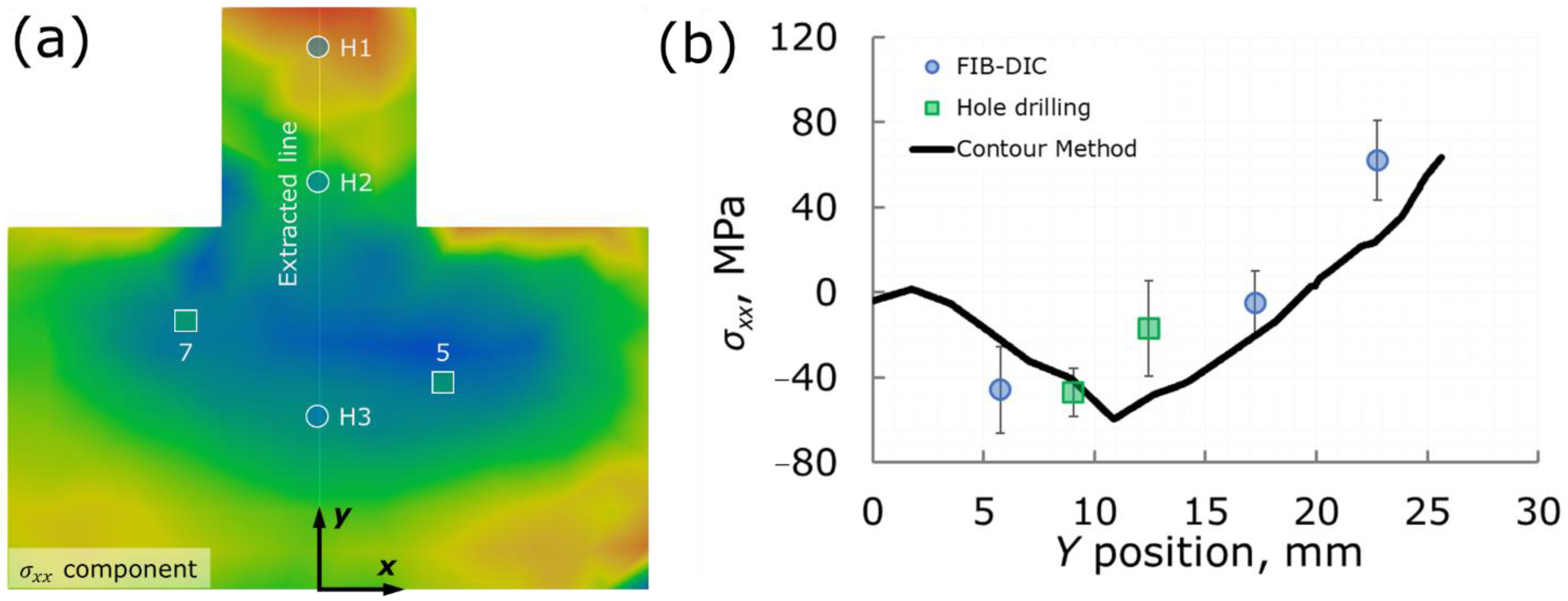
Figure 13 shows a comparison plot of all used methods. The results show that the calculations of the contour method solution provide a good match with FIB-DIC and hole drilling evaluations of the xx-component of residual stress, but the quantity and quality of experimental measurements should be increased in order to state that all direct components of residual stress can be calculated reliably using the present approach.
The present paper opens up new avenues toward further systematic studies of RS in 3D-printed parts and components. In particular, the paper established clear ways to distinguish and evaluate Type I, II, and III residual stresses, and identified the approaches most suitable, in the authors’ opinion, for experimental assessment of the dependence of these parameters on the fabrication and processing conditions.
To sum up, residual stresses in SLM 3D-printed metal parts appearing as a result of complex thermal history are frequently discussed in respect to many aspects of their mechanical performance and operation service life. Although recovery annealing or various surface treatments (sand blasting, shot peening, etc.) are readily applicable, the efficiency of these measures can hardly be assessed without relevant and robust techniques for routine experimental measurements. The popular X-ray diffraction method, especially in a laboratory, has a number of disadvantages, with shallow probing and averaging over large lighted areas being the most obvious of them.
Today, a growing number of experimental investigations are still based on X-ray diffraction measurements, which deprives researchers of much valuable information. SLM 3D-printable Al-Si-Mg alloys seem to the least studied in comparison with printable steels and Ti and Ni alloys.
We deliberately undertook comparative residual stress evaluation using methods of contour measurements, mechanical drilling with speckle-pattern interferometry, X-ray diffraction, and Xe-pFIB ring-core drilling with DIC analysis. These destructive and non-destructive methods have spatial resolutions ranging from tens of millimeters for contour measurements to units of millimeters for speckle-pattern interferometry, and finally, down to 70 micrometers for Xe-pFIB ring-core drilling. All methods returned estimations of residual stresses in good agreement in terms of signs and values regardless of dramatically different spatial resolution.
The surface of SLM 3D-printed parts are residually extended, with stresses having values equal to and exceeding yield strength at the locations where the fastest cooling takes place: protrusions, slim cross-sections, and supports. The middle parts of large cross-sections are residually compressed (perhaps hydrostatically), with relatively weak stresses of about from ¼ to ⅓ of yield strength.
We believe that these findings rationally explain the anisotropy of mechanical responses for the parts printed with different orientations in respect to fast scanning and growth direction.

Author Contributions

A.M.K., A.I.S., V.S.P. and D.K.R.; methodology, E.S.S., Y.V.K., S.A.L., S.I.E., A.G.S., Y.V.M. and P.A.S.; software, E.S.S., F.U. and S.I.E.; validation, E.S.S. and F.U.; formal analysis, A.I.S. and E.S.S.; investigation, E.S.S., S.A.L. and F.U.; resources, A.I.S., E.S.S., F.U. and A.M.K.; data curation, E.S.S. and Y.V.K.; writing—original draft preparation, A.I.S. and E.S.S.; writing—review and editing, A.M.K.; visualization, E.S.S.; supervision, project administration, funding acquisition, A.I.S. and A.M.K. All authors have read and agreed to the published version of the manuscript.

Funding

This research was funded by the Russian Science Foundation, grant number 21-19-00791, https://rscf.ru/en/project/21-19-00791/.

Data Availability Statement

The data are available from the corresponding authors upon request.

Acknowledgments

This research was funded by the Russian Science Foundation, grant number 21-19-00791, https://rscf.ru/en/project/21-19-00791/. The authors are grateful to the crew of the Fablab (Skoltech, Moscow, Russia) for their delicate and accurate sample preparations, and to Andrey Dyakov from CDMM (Skoltech, Moscow, Russia), who facilitated optical 3D scanning.

Conflicts of Interest

The authors declare no conflict of interest.

Appendix A

The scratch eliminating procedure was performed using the open-source OpenCV Python library using cv2.inpaint function [42], based on the algorithm proposed by Alexandru Telea [43]. The result is shown on Figure A1.
Figure A1. EBSD map (a) before and (b) after scratch elimination using inpainting procedure.
Metals 11 02064 g0a1

References

  1. Barriobero-Vila, P.; Gussone, J.; Stark, A.; Schell, N.; Haubrich, J.; Requena, G. Peritectic Titanium Alloys for 3D Printing. Nat. Commun. 2018, 9, 3426. [Google Scholar] [CrossRef] [PubMed]
  2. Aboulkhair, N.T.; Simonelli, M.; Parry, L.; Ashcroft, I.; Tuck, C.; Hague, R. 3D Printing of Aluminium Alloys: Additive Manufacturing of Aluminium Alloys using Selective Laser Melting. Prog. Mater. Sci. 2019, 106, 100578. [Google Scholar] [CrossRef]
  3. Liu, Z.; He, B.; Lyu, T.; Zou, Y. A Review on Additive Manufacturing of Titanium Alloys for Aerospace Applications: Directed Energy Deposition and Beyond Ti-6Al-4V. JOM 2021, 73, 1804–1818. [Google Scholar] [CrossRef]
  4. Webster, G.A.; Ezeilo, A.N. Residual Stress Distributions and Their Influence on Fatigue Lifetimes. Int. J. Fatigue 2001, 23, 375–383. [Google Scholar] [CrossRef]
  5. Carter, T.J. Common Failures in Gas Turbine Blades. Eng. Fail. Anal. 2005, 12, 237–247. [Google Scholar] [CrossRef]
  6. Zerbst, U.; Bruno, G.; Buffiere, J.-Y.; Wegener, T.; Niendorf, T.; Wu, T.; Zhang, X.; Kashaev, N.; Meneghetti, G.; Hrabe, N.; et al. Damage Tolerant Design of Additively Manufactured Metallic Components Subjected to Cyclic Loading: State of the Art and Challenges. Prog. Mater. Sci. 2021, 121, 100786. [Google Scholar] [CrossRef] [PubMed]
  7. Song, X.; Zhai, W.; Huang, R.; Fu, J. Metal-Based 3D-Printed Micro Parts & Structures. In Reference Module in Materials Science and Materials Engineering; Elsevier: Amsterdam, The Netherlands, 2020. [Google Scholar]
  8. Korsunsky, A.M.; Regino, G.M.; Nowell, D. Variational Eigenstrain Analysis of Residual Stresses in a Welded Plate. Int. J. Solids Struct. 2007, 44, 4574–4591. [Google Scholar] [CrossRef] [Green Version]
  9. Gibbons, D.W.; Serfontein, J.P.L.; van der Merwe, A.F. Mapping the path to certification of metal laser powder bed fusion for aerospace applications. Rapid Prototyp. J. 2021, 27, 355–361. [Google Scholar] [CrossRef]
  10. Mezghani, A.; Nassar, A.R.; Dickman, C.J.; Valdes, E.; Alvarado, R. Laser powder bed fusion additive manufacturing of copper wicking structures: Fabrication and capillary characterization. Rapid Prototyp. J. 2021, 27, 1181–1188. [Google Scholar] [CrossRef]
  11. Li, L.; Pan, T.; Zhang, X.; Chen, Y.; Cui, W.; Yan, L.; Liou, F. Deformations and stresses prediction of cantilever structures fabricated by selective laser melting process. Rapid Prototyp. J. 2021, 27, 453–464. [Google Scholar] [CrossRef]
  12. Zhang, B.; Han, X.; Chen, C.; Zhang, W.; Liao, H.; Chen, B. Effect of the strut size and tilt angle on the geometric characteristics of selective laser melting AlSi10Mg. Rapid Prototyp. J. 2021, 27, 879–889. [Google Scholar] [CrossRef]
  13. Guan, J.; Wang, Q.; Chen, C.; Xiao, J. Forming feasibility and interface microstructure of Al/Cu bimetallic structure fabricated by laser powder bed fusion. Rapid Prototyp. J. 2021, 27, 1337–1345. [Google Scholar] [CrossRef]
  14. Casavola, C.; Pappalettere, C.; Tursi, F. Residual Stress on AISI 300 Sintered Materials. In Experimental and Applied Mechanics; Conference Proceedings of the Society for Experimental Mechanics Series; Springer: New York, NY, USA, 2011; Volume 6, pp. 201–208. [Google Scholar]
  15. Bartlett, J.L.; Li, X. An Overview of Residual Stresses in Metal Powder Bed Fusion. Addit. Manuf. 2019, 27, 131–149. [Google Scholar] [CrossRef]
  16. Lopez, C.; Elias-Zuniga, A.; Jimenez, I.; Martinez-Romero, O.; Siller, H.R.; Diabb, J.M. Experimental Determination of Residual Stresses Generated by Single Point Incremental Forming of AlSi10Mg Sheets Produced using SLM Additive Manufacturing Process. Materials 2018, 11, 2542. [Google Scholar] [CrossRef] [Green Version]
  17. Karolus, M.; Maszybrocka, J.; Stwora, A.; Skrabalak, G. Residual Stresses of AlSi10Mg Fabricated by Selective Laser Melting. Arch. Metall. Mater. 2019, 64, 1011–1016. [Google Scholar]
  18. Colombo, C.; Biffi, C.A.; Fiocchi, J.; Tuissi, A.; Vergani, L.M. Effect of Optimized Heat Treatments on the Tensile Behavior and Residual Stresses of Selective Laser Melted AlSi10Mg Samples. Key Eng. Mater. 2019, 813, 364–369. [Google Scholar] [CrossRef]
  19. Xing, X.; Duan, X.; Sun, X.; Gong, H.; Wang, L.; Jiang, F. Modification of Residual Stresses in Laser Additive Manufactured AlSi10Mg Specimens using an Ultrasonic Peening Technique. Materials 2019, 12, 455. [Google Scholar] [CrossRef] [Green Version]
  20. Di Giovanni, M.T.; de Menezes, J.T.O.; Bolelli, G.; Cerri, E.; Castrodeza, E.M. Fatigue Crack Growth Behavior of a Selective Laser Melted AlSi10Mg. Eng. Fract. Mech. 2019, 217, 106564. [Google Scholar] [CrossRef]
  21. Mfusi, B.J.; Mathe, N.R.; Tshabalala, L.C.; Popoola, P.A.I. The Effect of Stress Relief on the Mechanical and Fatigue Properties of Additively Manufactured AlSi10Mg Parts. Metals 2019, 9, 1216. [Google Scholar] [CrossRef] [Green Version]
  22. Song, X.; Feih, S.; Zhai, W.; Sun, C.N.; Li, F.; Maiti, R.; Wei, J.; Yang, Y.; Oancea, V.; Romano Brandt, L.; et al. Advances in Additive Manufacturing Process Simulation: Residual Stresses and Distortion Predictions in Complex Metallic Components. Mater. Des. 2020, 193, 108779. [Google Scholar] [CrossRef]
  23. Beretta, S.; Gargourimotlagh, M.; Foletti, S.; du Plessis, A.; Riccio, M. Fatigue Strength Assessment of “as Built” AlSi10Mg Manufactured by SLM with Different Build Orientations. Int. J. Fatigue 2020, 139, 105737. [Google Scholar] [CrossRef]
  24. Amir, B.; Grinberg, E.; Gale, Y.; Sadot, O.; Samuha, S. Influences of Platform Heating and Post-processing Stress Relief Treatment on the Mechanical Properties and Microstructure of Selective-Laser-Melted AlSi10Mg Alloys. Mater. Sci. Eng. A 2021, 822, 141612. [Google Scholar] [CrossRef]
  25. Bhaduri, D.; Ghara, T.; Penchev, P.; Paul, S.; Pruncu, C.I.; Dimov, S.; Morgan, D. Pulsed Laser Polishing of Selective Laser Melted Aluminium Alloy Parts. Appl. Surf. Sci. 2021, 558, 149887. [Google Scholar] [CrossRef]
  26. Korsunsky, A.M.; Sebastiani, M.; Bemporad, E. Focused Ion Beam Ring Drilling for Residual Stress Evaluation. Mater. Lett. 2009, 63, 1961–1963. [Google Scholar] [CrossRef]
  27. Lord, J.; Cox, D.; Ratzke, A.; Sebastiani, M.; Korsunsky, A.; Mughal, M.; Salvati, E. A Good Practice Guide for Measuring Residual Stresses Using FIB-DIC; National Physical Laboratory: Teddington, UK, 2018. [Google Scholar]
  28. Statnik, E.S.; Nyaza, K.V.; Salimon, A.I.; Ryabov, D.; Korsunsky, A.M. In Situ SEM Study of the Micro-Mechanical Behaviour of 3D-Printed Aluminium Alloy. Technologies 2021, 9, 21. [Google Scholar] [CrossRef]
  29. Somov, P.A.; Statnik, E.S.; Malakhova, Y.V.; Nyaza, K.V.; Salimon, A.I.; Ryabov, D.K.; Korsunsky, A.M. On the Grain Microstructure-Mechanical Properties Relationships in Aluminium Alloy Parts Fabricated by Laser Powder Bed Fusion. Metals 2021, 11, 1175. [Google Scholar] [CrossRef]
  30. Uzun, F.; Korsunsky, A.M. On the Identification of Eigenstrain Sources of Welding Residual Stress in Bead-on-plate Inconel 740H Specimens. Int. J. Mech. Sci. 2018, 145, 231–245. [Google Scholar] [CrossRef]
  31. Kartal, M.E.; Kang, Y.H.; Korsunsky, A.M.; Cocks, A.C.F.F.; Bouchard, J.P. The Influence of Welding Procedure and Plate Geometry on Residual Stresses in Thick Components. Int. J. Solids Struct. 2016, 80, 420–429. [Google Scholar] [CrossRef]
  32. Sebastiani, M.; Sui, T.; Korsunsky, A.M. Residual Stress Evaluation at the Micro- and Nano-scale: Recent Advancements of Measurement Techniques, Validation through Modelling, and Future Challenges. Mater. Des. 2017, 118, 204–206. [Google Scholar] [CrossRef]
  33. Pisarev, V.S.; Odintsev, I.N.; Eleonsky, S.I.; Apalkov, A.A. Residual Stress Determination by Optical Interferometric Measurements of Hole Diameter Increments. Opt. Lasers Eng. 2018, 110, 437–456. [Google Scholar] [CrossRef]
  34. Everaerts, J.; Salvati, E.; Uzun, F.; Romano Brandt, L.; Zhang, H.; Korsunsky, A.M. Separating Macro-(Type I) and Micro-(Type II+III) Residual Stresses by Ring-Core FIB-DIC Milling and Eigenstrain Modelling of a Plastically Bent Titanium Alloy Bar. Acta Mater. 2018, 156, 43–51. [Google Scholar] [CrossRef]
  35. Winiarski, B.; Rue, C.; Withers, P.J. Plasma FIB Spin Milling for 3D Residual Stress Measurements. Microsc. Microanal. 2019, 25, 882–883. [Google Scholar] [CrossRef] [Green Version]
  36. Senn, M. Digital Image Correlation and Tracking. In MATLAB Central File Exchange; 2021; Available online: https://www.mathworks.com/matlabcentral/fileexchange/50994-digital-image-correlation-and-tracking (accessed on 14 December 2021).
  37. Roy, M.J.; Stoyanov, N.; Moat, R.J.; Withers, P.J. pyCM: An Open-Source Computational Framework for Residual Stress Analysis Employing the Contour Method. SoftwareX 2020, 11, 100458. [Google Scholar] [CrossRef]
  38. Smith, M.; Levesque, J.B.; Bichler, L. Residual stress analysis in linear friction welded in-service Inconel 718 superalloy via neutron diffraction and contour method approaches. Mater. Sci. Eng. 2017, 691, 168–179. [Google Scholar] [CrossRef]
  39. Lunt, A.J.G.; Salvati, E.; Ma, L.; Dolbyna, I.P.; Neo, T.K.; Korsunsky, A.M. Full in-plane Strain Tensor Analysis using the Microscale Ring-Core FIB Milling and DIC Approach. J. Mech. Phys. Solids 2016, 94, 47–67. [Google Scholar] [CrossRef]
  40. Abboud, E.; Attia, H.; Shi, B.; Damir, A.; Thomson, V.; Mebrahtu, Y. Residual Stresses and Surface Integrity of Ti-alloys During Finish Turning—Guidelines for Compressive Residual Stresses. Procedia CIRP 2016, 45, 55–58. [Google Scholar] [CrossRef] [Green Version]
  41. Aboulkhair, N.T.; Maskery, I.; Tuck, C.; Ashcroft, I.; Everitt, N.M. The Microstructure and Mechanical Properties of Selectively Laser Melted AlSi10Mg: The Effect of a Conventional T6-like Heat Treatment. Mater. Sci. Eng. A 2016, 667, 139–146. [Google Scholar] [CrossRef]
  42. OpenCV Documentation. Inpainting. Available online: https://docs.opencv.org/4.x/d7/d8b/group__photo__inpaint.html (accessed on 14 December 2021).
  43. Telea, A. An image inpainting technique based on the fast marching method. J. Graph. Tools 2004, 9, 23–34. [Google Scholar] [CrossRef]
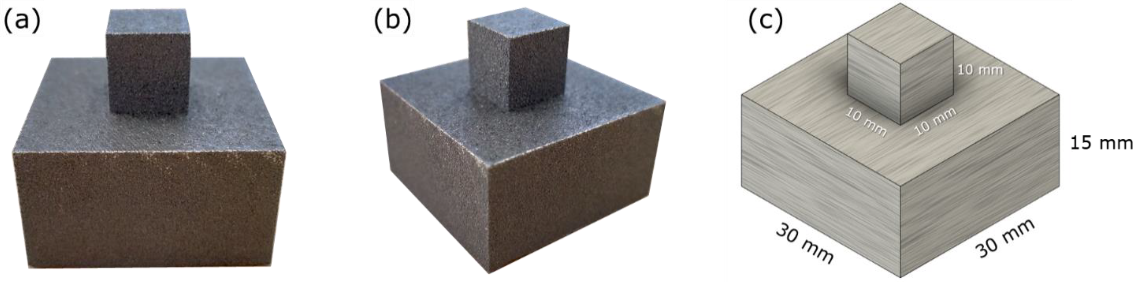
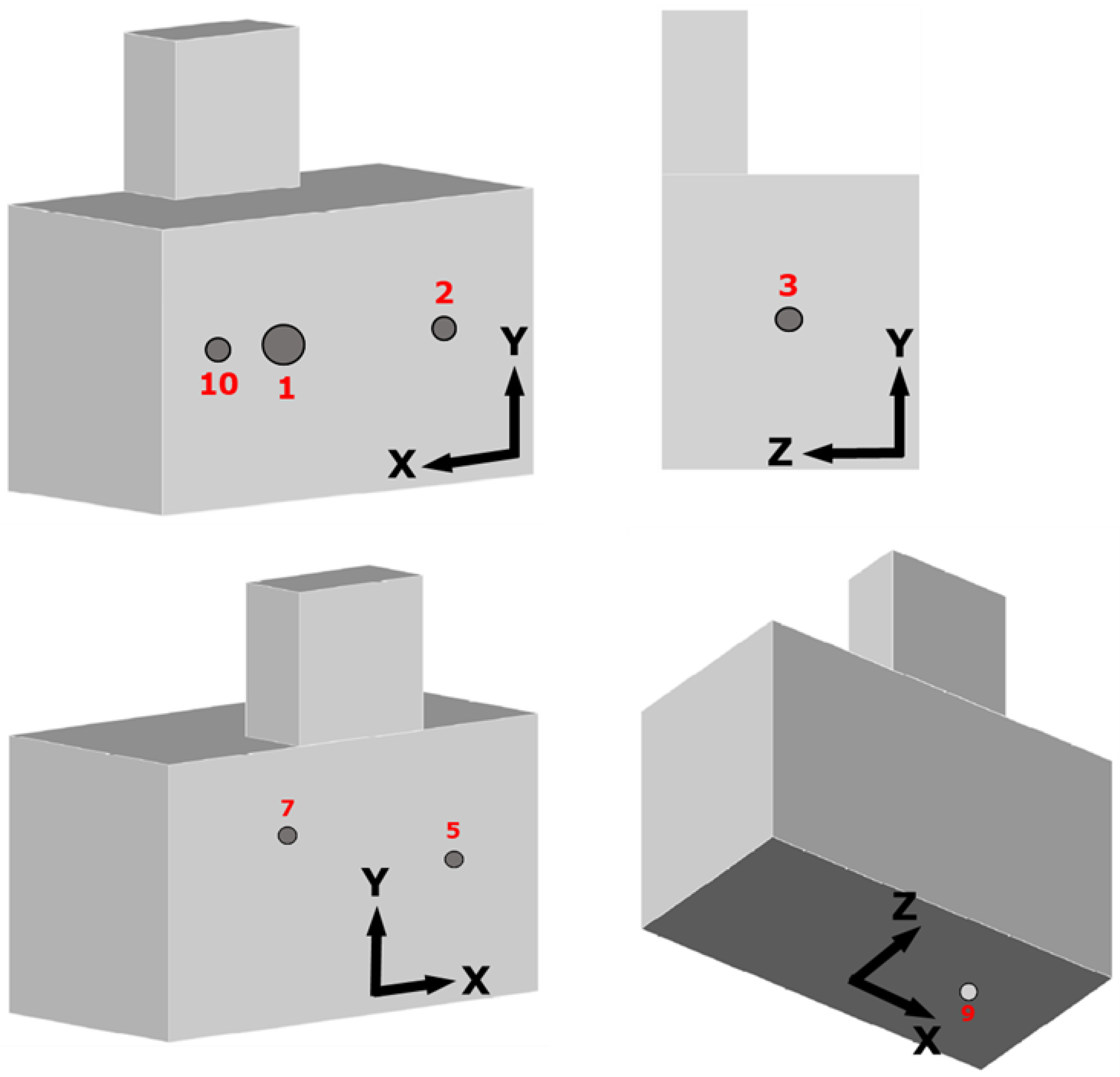
Figure 1. The appearance of the double tower shape sample in the as-printed state: (a) front view, (b) side view, (c) dimensions.
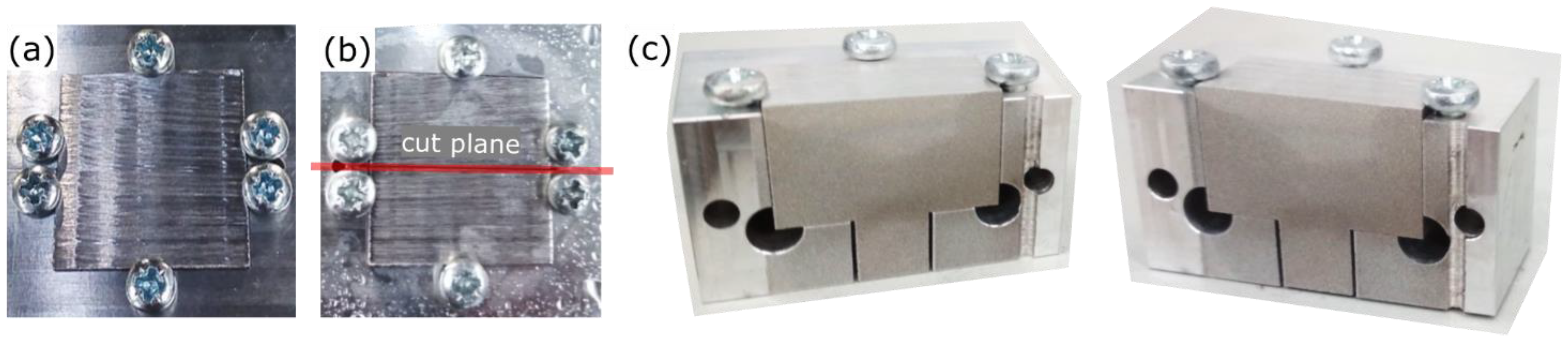
Metals 11 02064 g001
Figure 2. The appearance of the double tower sample (a) before and (b,c) after EDM cutting: (b) top view with the indicated cut plane (red line) and (c) sectional view.
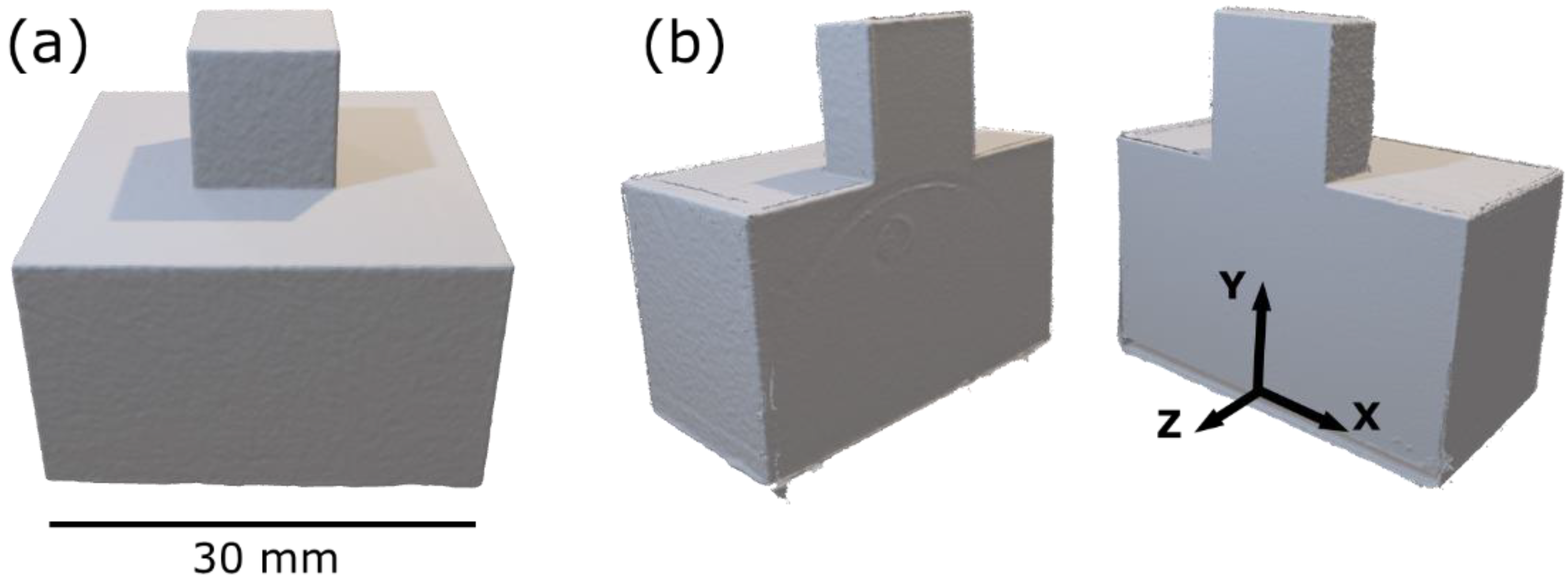
Metals 11 02064 g002
Figure 3. The appearance of double tower shaped sample as 3D models: (a) before and (b) after EDM cutting in half with the indicated primary coordinate system according to which all used methods are aligned.
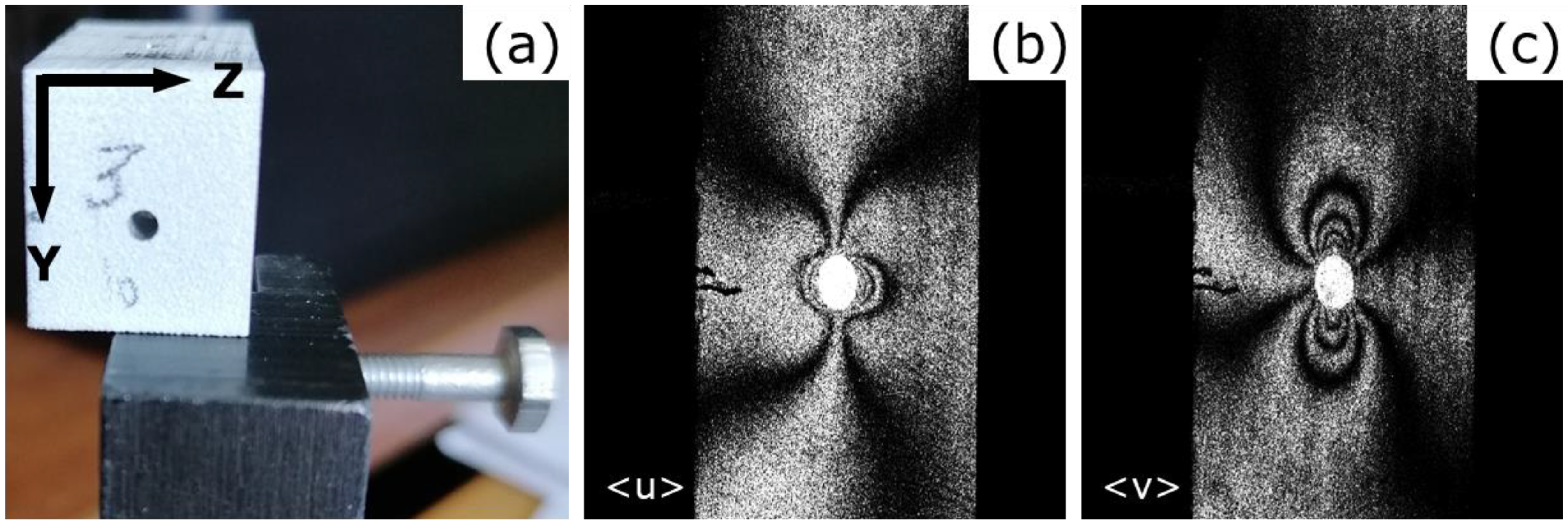
Metals 11 02064 g003
Figure 4. (a) general view of vertical outer face of the half-cut double tower perpendicular to the sectioning plane with the drill hole, and (b,c) interference fringe patterns obtained as a result of 1.9 mm diameter hole drilling: (b) the horizontal in-plane displacement component and (c) the vertical in-plane displacement component.
Metals 11 02064 g004
Figure 5. 
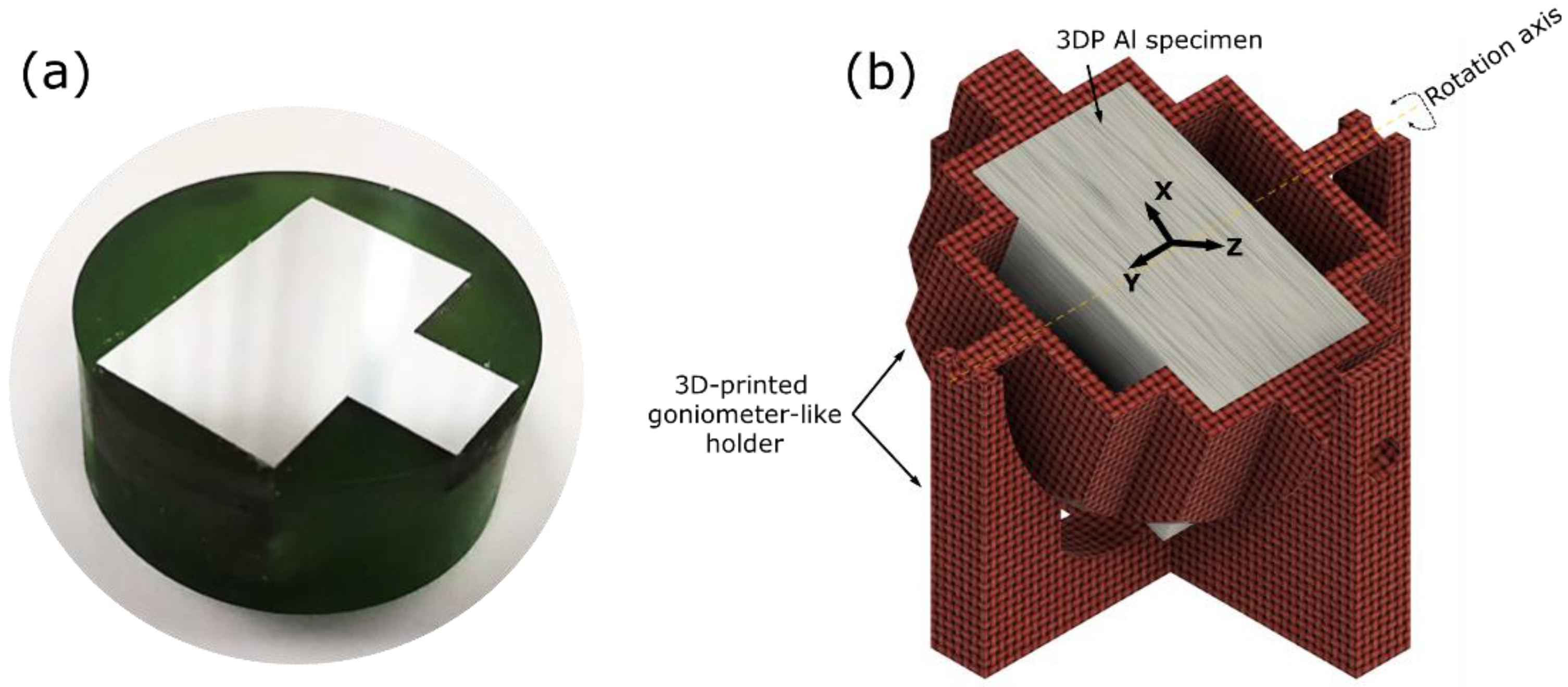
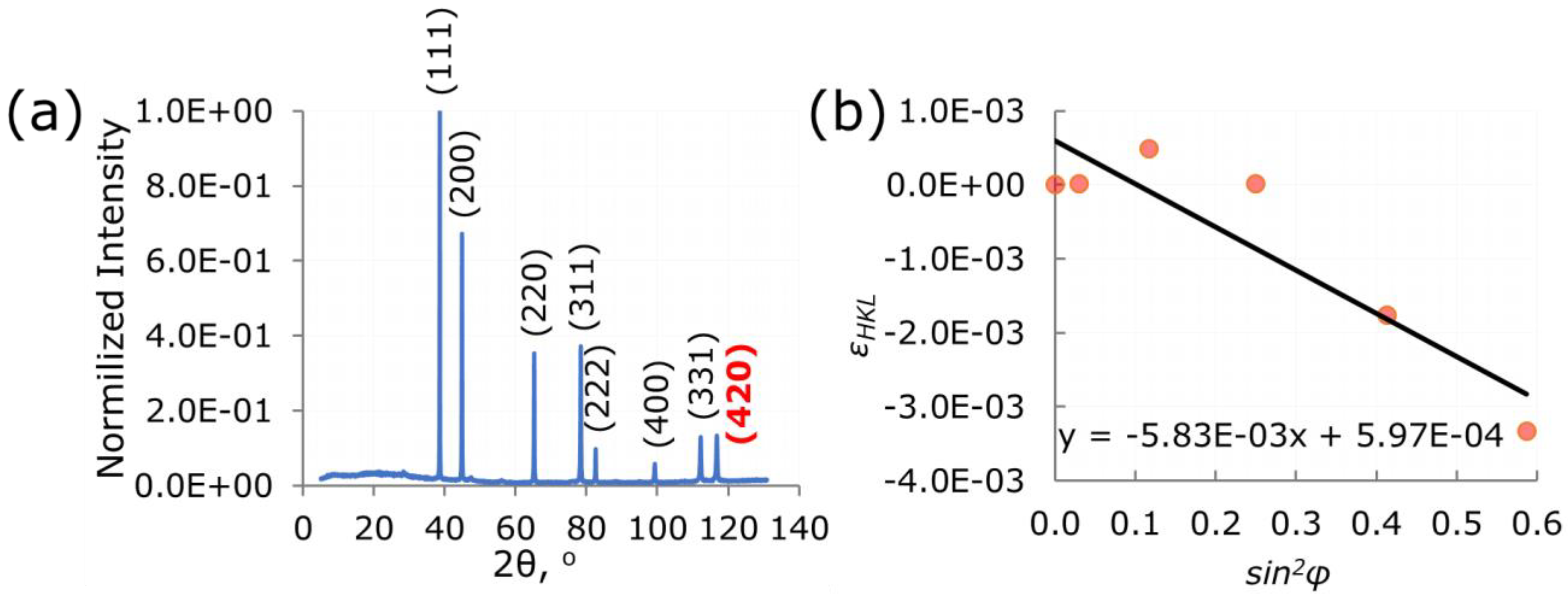
Appearance of the polished half-cut double tower sample: (a) mounted in conductive resin for FIB-SEM studies, (b) fixed in the goniometer-like sample holder for X-ray diffraction measurements.
Metals 11 02064 g005
Figure 6. 
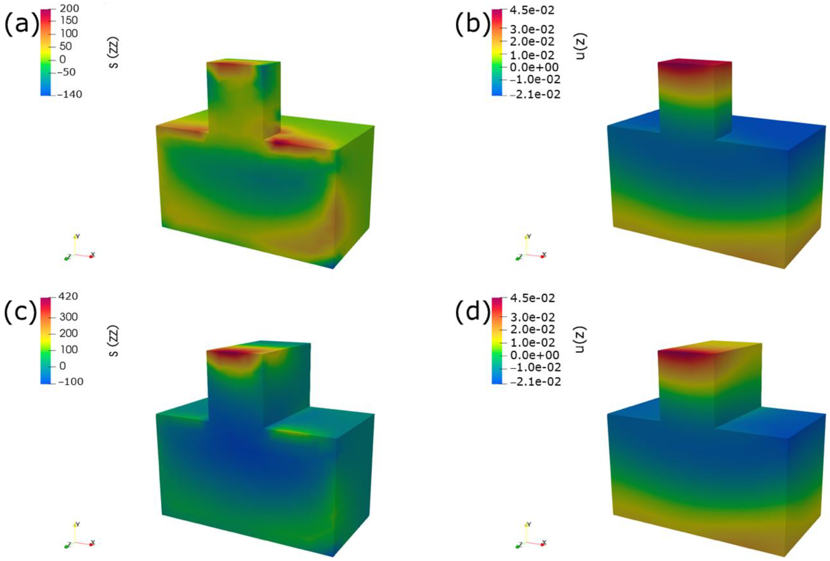
Illustration of the distribution of the zz-component of residual stresses (a,c) and z-component of displacements (b,d) in the real (a,b) and continuously processed (c,d) geometry models, respectively.
Metals 11 02064 g006
Figure 7. 
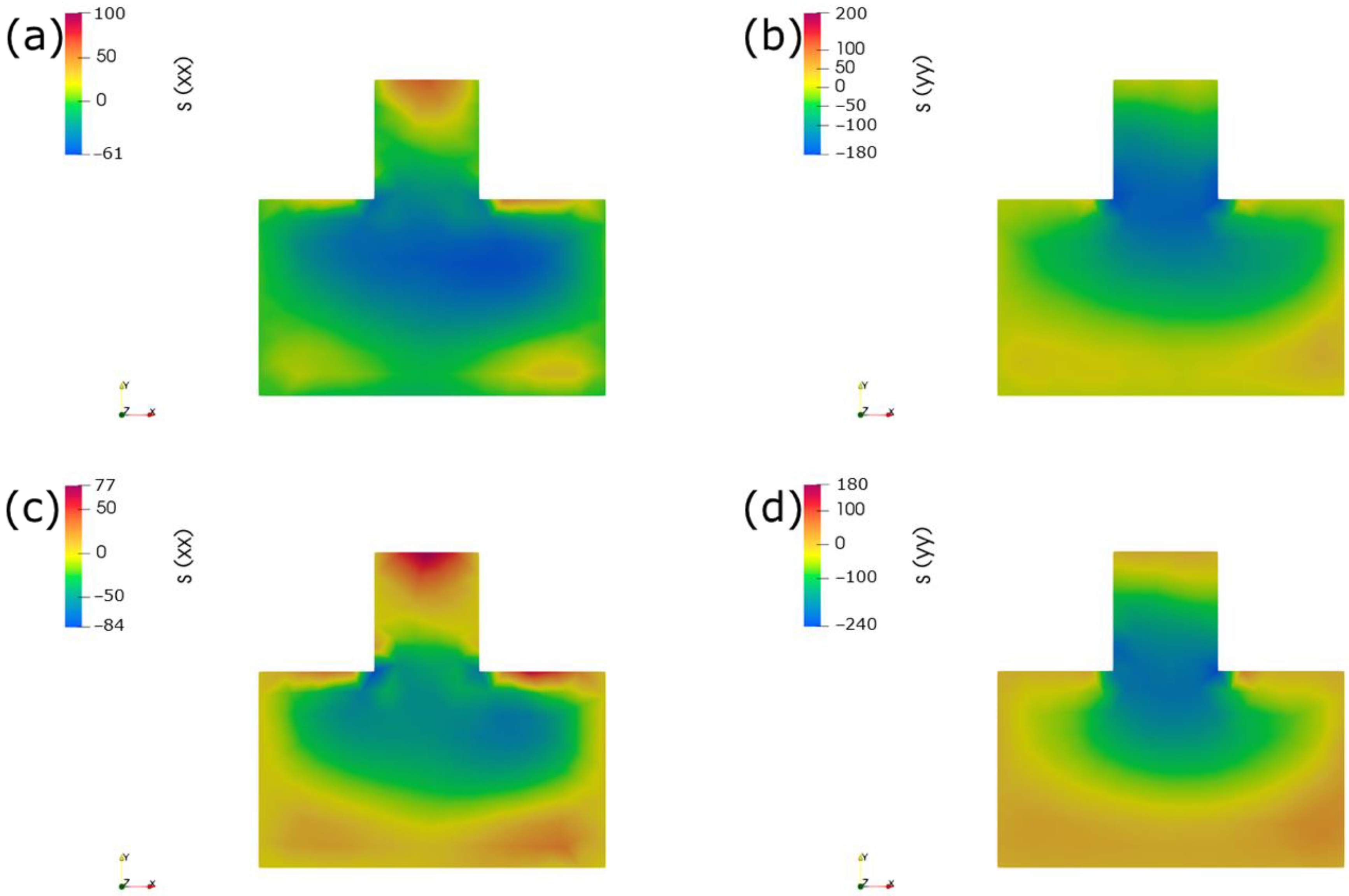
Illustration of distribution of xx- (a,c) and yy- (b,d) components of residual stresses in the real (a,b) and continuous (c,d) geometry models, respectively.
Metals 11 02064 g007
Figure 8. 
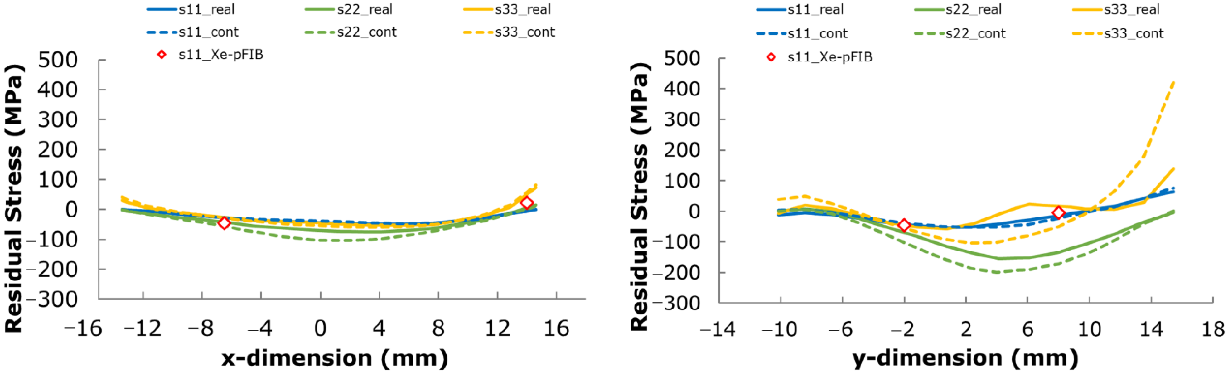
Line plots of xx (s11), yy (s22), and zz (s33) components of residual stress along the (a) horizontal (x) and (b) vertical (y) lines illustrated by the dashed lines on the sectioned surface in Figure 12 below.
Metals 11 02064 g008
Figure 9. 
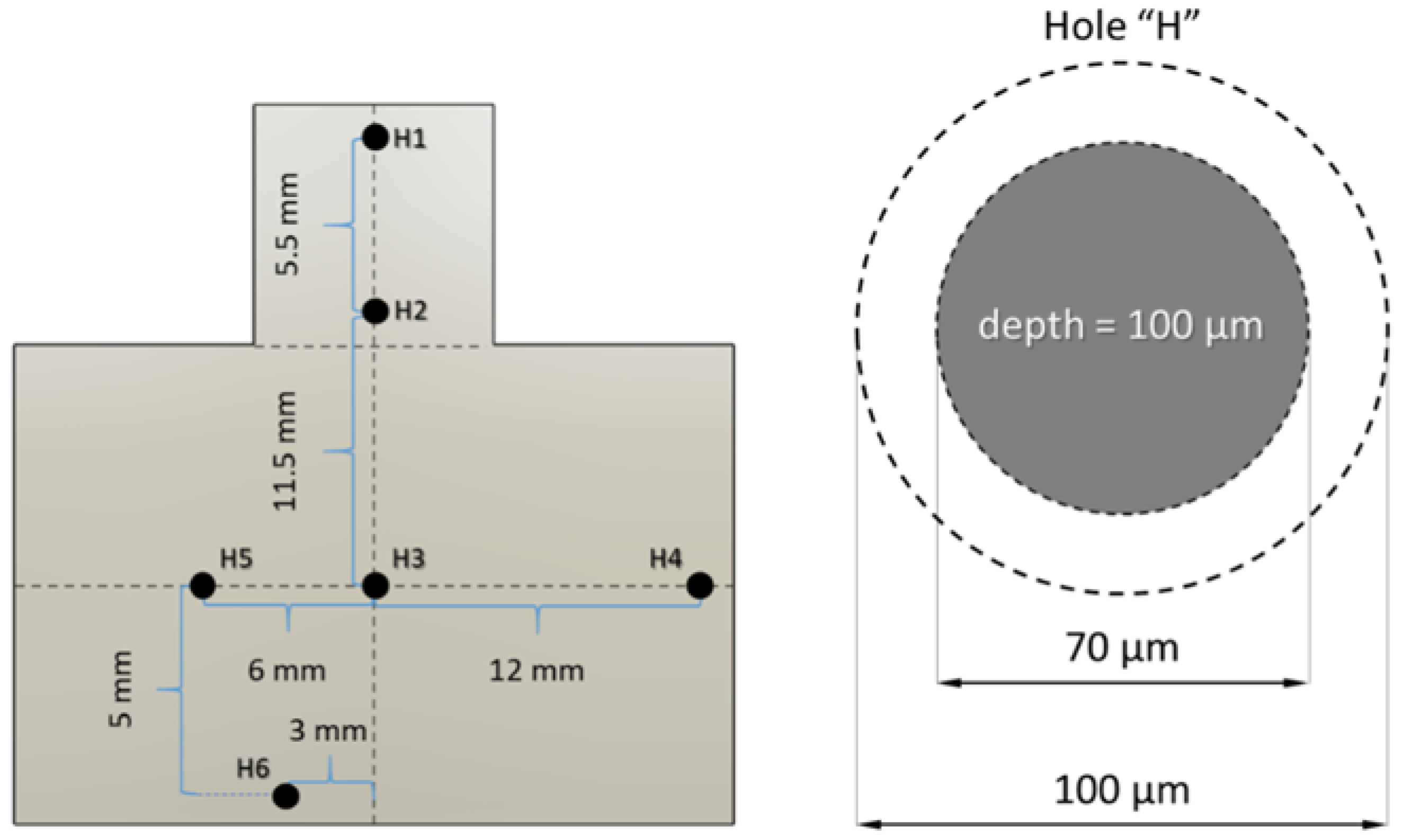
Locations of holes for the hole drilling method with the indicated axis.
Metals 11 02064 g009
Figure 10. Details of X-ray measurement of residual stresses at the cut plane: (a) measured I ~ 2 θ plot for the specimen (highlighted red plane ( 420 ) was selected for the next calculations); (b) ε H K L ~ sin 2 φ plot.
Metals 11 02064 g010
Figure 11. 
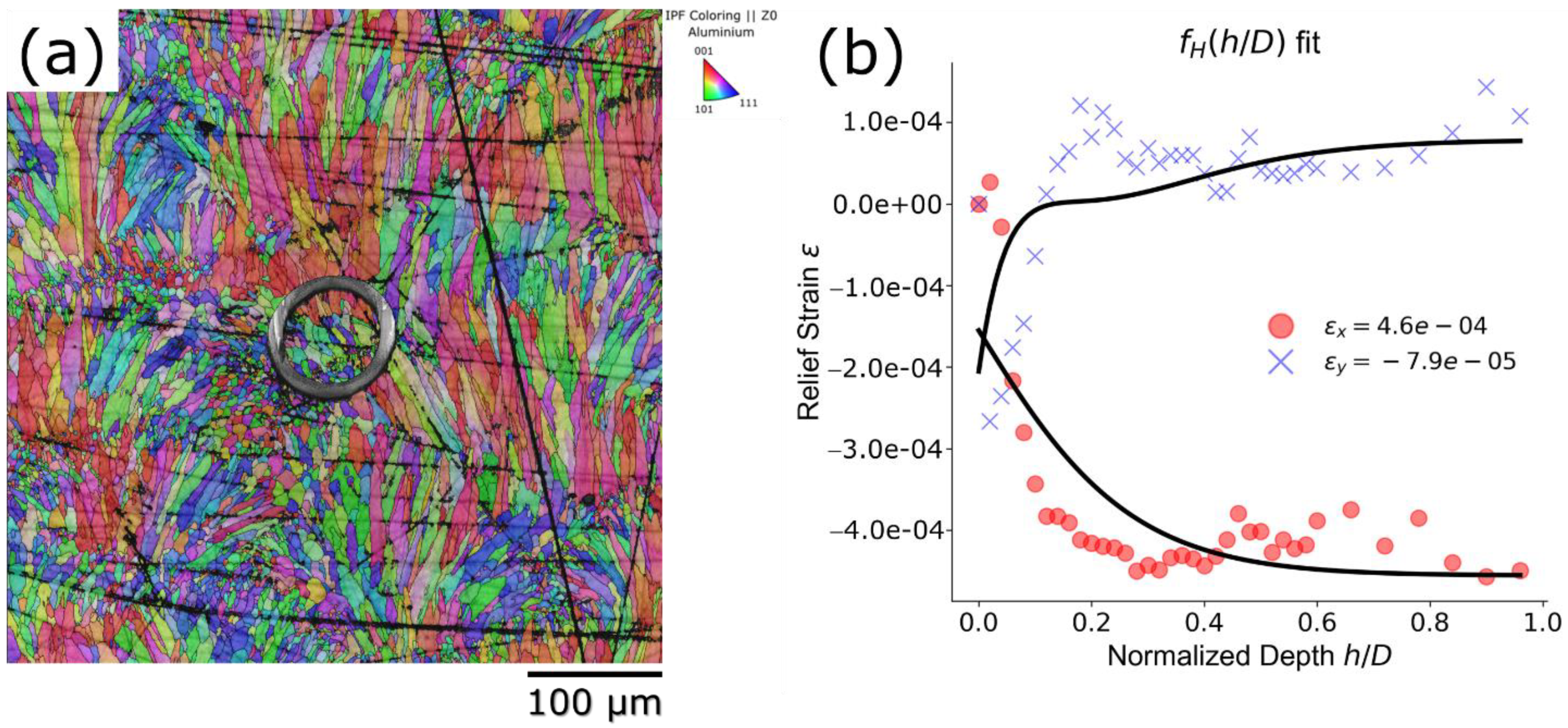
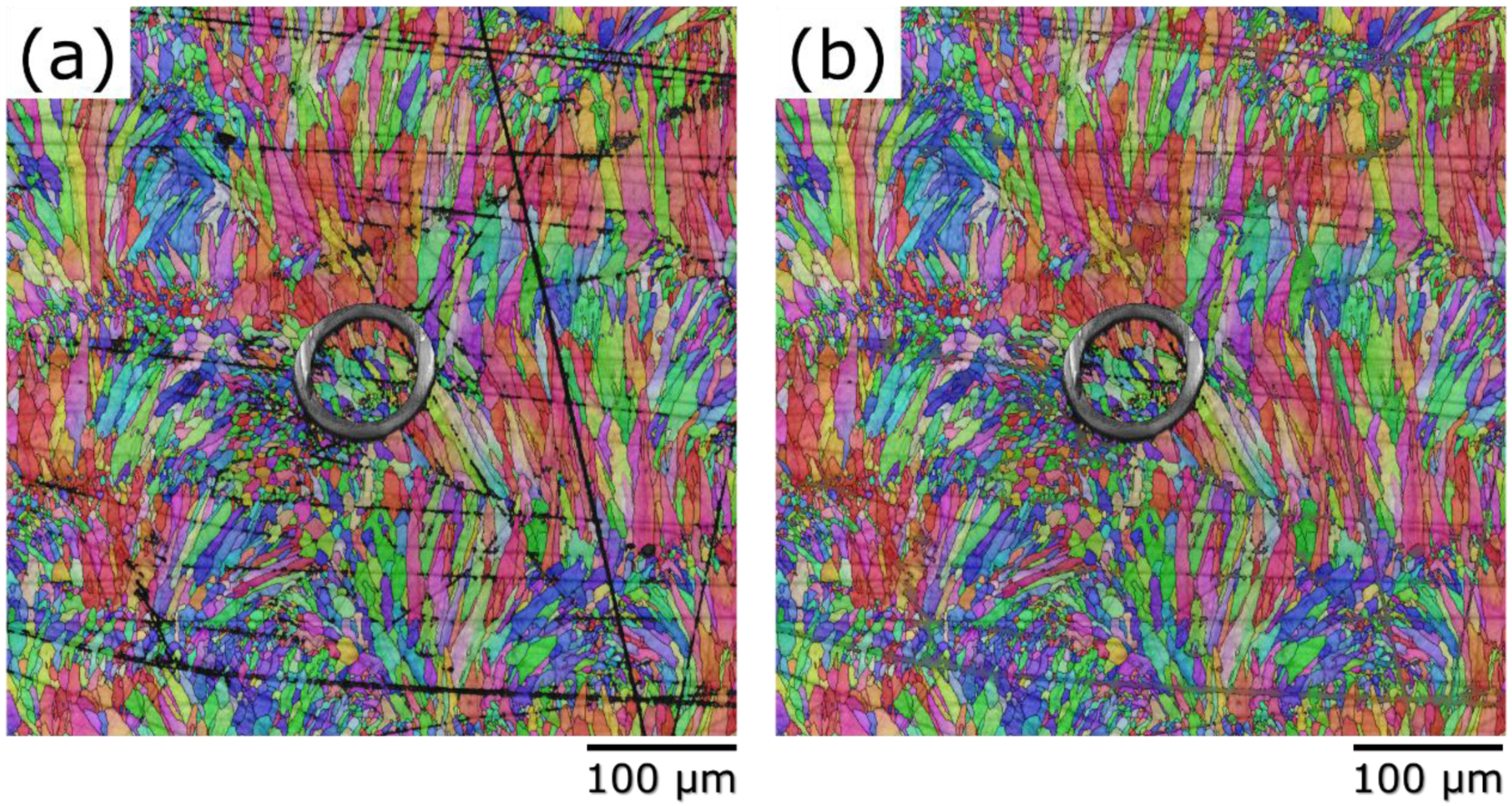
Details of Xe-pFIB ring-core drilling measurements of residual stresses at the cut plane: (a) combined EBSD map with the Euler’ colors and milled ring, and (b) measured relief strains with the fitting curve.
Metals 11 02064 g011
Figure 12. Mapping of residual stresses using Xe-pFIB ring-core drilling method.
Metals 11 02064 g012
Figure 13. Comparison of all used methods: (a) the locations of the measured points and the plotting line, superimposed on the contour map of the horizontal stress component reconstructed by the contour method; (b) residual stress line plot.
Metals 11 02064 g013
Table 1. Residual stresses at half-cut double tower sample faces.
NDescription of Location σ , MPa
1Vertical outer face parallel to the cut plane 120   ( σ x x )
2 118   ( σ x x )
10 129   ( σ x x )
3Vertical outer face perpendicular to the cut plane 31   ( σ z z )
5Cut plane 47   ( σ x x )
7 17   ( σ x x )
9Bottom of the base 11   ( σ x x )
Table 2. Residual stresses at faces and cut plane of half-cut double tower specimens.
N σ x x ,   MPa
H162.1
H2−4.9
H3−45.8
H433.4
H522.8
H6−78.7
Publisher’s Note: MDPI stays neutral with regard to jurisdictional claims in published maps and institutional affiliations.

