Article

A Study on the Fiber YAG Laser Welding of 304L Stainless Steel

by
Essam R. I. Mahmoud
1,2,*,
Hamad Almohamadi
3,
Abdulrahman Aljabri
1 and
Mohamed Abdelghany Elkotb
4,5
1
Department of Mechanical Engineering, Islamic University of Madinah, Medina 42351, Saudi Arabia
2
Central Metallurgical Research and Development Institute (CMRDI), Cairo 11421, Egypt
3
Department of Chemical Engineering, Islamic University of Madinah, Medina 42351, Saudi Arabia
4
Mechanical Engineering Department, College of Engineering, King Khalid University, Abha 62529, Saudi Arabia
5
Mechanical Engineering Department, Faculty of Engineering, Kafrelsheikh University, Kafr El Sheikh 33516, Egypt
*
Author to whom correspondence should be addressed.
Metals 2021, 11(12), 2022; https://doi.org/10.3390/met11122022
Submission received: 13 November 2021 / Revised: 4 December 2021 / Accepted: 12 December 2021 / Published: 14 December 2021

Abstract

:
This work aims to optimize the main YAG fiber laser parameters to weld 304L stainless steel plates of 3 mm thick. Different laser powers (2500, 2000, and 1500 W) and speeds (60, 40, and 20 mm/s) were used and merged in heat input, maintaining the defocusing distance at –2 mm to get full penetration. The weld quality and the effect of the laser heat input on the microstructures of the weld and heat-affected zones were investigated. Besides, the fracture strength of the welded joints and hardness distribution through the cross-sections were evaluated. The weld width has a direct relationship with heat input. The laser power of 2800 W produced full penetration joints without any macro defects while reduction in laser power pronounced partial penetration defects. The size of the heat-affected zone in all the processing parameters was very small. The microstructure of the weld zone shows columnar dendrite austenite grains with small arm spacing in most of the welded zone. The size of the dendrites became finer at lower heat input. At a higher heat input, a reasonable amount of lathy equiaxed grains with some delta ferrite occurred. A small amount of delta ferrite was detected in the heat-affected zone, which prevented the crack formation. The hardness of the weld metal was much higher than that of the base metal in all processing parameters and it has a reverse relationship with the heat input. The fracture strength of the welded joints was very close to that of the base metal in the defect-free samples and it increased with decreasing the heat input.

1. Introduction

Alloys 304 and 304L stainless steels are extensively used as austenitic stainless steel alloys. Alloy 304L is a low-carbon version of the 304 stainless steel alloy with a carbon content that reaches 0.03%. This low carbon content is attributed to the typical corrosion resistance in 304L stainless steel. Chromium depletion from the grain boundaries is avoided because of the unavailability of sufficient carbon for carbide formation in the process of sensitization [1,2,3]. Alloy 304L exhibits deep drawing capacity with excellent resistance to corrosion as well as relative ease in fabrication. Due to these properties, it finds a wide spectrum of applications, especially in nuclear applications (Pumps, steam lines, spend fuels reprocessing, and transport), food processing industry (breweries, milk, etc.), kitchen features (sinks, platforms, equipment, appliances, etc.), architecture industry (trims, molds, panels, etc.), marine applications, fasteners, heat exchangers, chemical containers, welded, and woven water filtration screens, etc. [4,5,6,7,8].
Stainless steel alloys that are welded by normal arc welding methods, such as gas metal arc welding (MAG and MIG), gas tungsten arc welding (TIG), and shielded metal arc welding [9,10], suffer from many difficulties in terms of sensitization. The interrelated shortcomings include cracks in weld-metal, wide heat-affected zone (HAZ), development of carbides, weld decay, and reduction in corrosion resistance. During welding, the weld metal and its adjacent areas undergo heating/cooling with a temperature range of 500–850 °C for a relatively long time. In this temperature range, chromium carbide precipitates alongside the grain boundaries, causing depletion of chromium inside the grains leading to intergranular corrosion, as well as intergranular stress cracking. Additionally, prolonged exposures to a lower temperature range such as 300–500 °C causes the carbide nucleated that occurred at higher temperatures to be coarsened and causes low-temperature sensitization. Extended exposure to these temperatures in fusion welding processes decreases the weld quality. If the exposure to these high temperatures is short-lived, even after nucleation of the carbides, the propagation is limited and chromium depletion can be restricted [11]. Moreover, the most prevalent fusion welding technique in the case of austenitic steels, i.e., TIG welding, poses limitations of single-pass thickness, low rate of cooling, low welding speeds, the requirement of edge preparation, and lack of automation, etc. Moreover, due to the lower thermal conductivity of stainless steels, high-temperature weld pools created by conventional fusion welding processes result in wider HAZ. By increasing the thickness of the stainless steels being welded, the welding speed decreases and the effects of high heat generated for longer periods become serious problems [12,13,14]. Moreover, the composition of the constituents in the shielding gas greatly affects the quality of the welding joints made by the TIG process. Argon is the most widely used commercially shielding gas. Adding other gases such as helium, hydrogen, carbon dioxide, nitrogen, and oxygen in different percentages have direct effects on weld shape, microstructure, and mechanical properties [15,16]. Moreover, solidification occurs during welding of the 300 series of stainless steels as a blend of main austenite and few ferrite phases to avoid hot cracking. Primary ferritic solidification is required to provide a higher solubility of impurities such as S and P, which is the main cause of hot cracking [15,16]. During cooling, the ferrite phase transforms mostly to austenite, but minor quantities of δ-ferrite may still be present in the weld metal. The presence of δ-ferrite in this remaining quantity is insignificant to affect the intergranular corrosion, but it improves the stress corrosion resistance of the ferritic-austenitic welds [17,18]. Most of the previous limitations can be avoided if a concentrated low heat input welding process is used. Moreover, the distortion of stainless steels during welding, due to its high thermal expansion coefficient, can be greatly minimized with low heat input welding processes [19,20]. Laser welding is considered an optimum solution to overcome most of the above limitations [21].
Laser welding has a higher weld depth to width ratio with lower heat input compared to other traditional fusion welding processes. This results in a low possibility of formation of chromium carbides and sensitization, though the process parameters need to be selected carefully [22,23,24]. The fibre YAG laser is considered to be one of the advanced laser technologies, which was developed recently for many industrial applications. Compared to other laser techniques, it is more flexible as it has higher power, low maintenance requirements, and high automation adaptability [19,20,21]. Welding speed and laser power are the key process variables in the welding process which control the amount of energy generated to be used in welding [25]. Gnanasekaran et al. [26] used pulsed YAG laser to weld 304 austenitic stainless steel. They studied the effect of laser power on the microstructure and mechanical properties of the welded joints. It was shown that with increasing laser power, joint penetration was improved but the weld bead was widened [26]. Saravanan et. al. [27] presented the influence of heat generated by using YAG laser different parameters on the duplex stainless steel weld joints’ microstructure, hardness, and tensile strength. Complete penetrations were achieved at lower heat input. While grain growth was observed at higher heat input. The maximum mechanical properties were obtained at lower heat input [27]. In another work presented by Abdo et al. [28], the effect of heat input parameters of pulsed YAG laser on the corrosion resistance of 2205 duplex stainless steel welded joints were reported. The welded joints obtained at a higher pulse energy showed higher corrosion resistance than that obtained at a low pulse energy [28]. Li et al. [29] explored the thermal performance and solidification characteristics of 304 stainless steel during laser welding. They suggested an upgraded understanding of the relationships of the temperature distribution with metallurgical behavior and surface stresses. The surface tension was smaller at higher temperature areas [29].
In this direction, this work aims to use a fibre YAG laser to weld 304L stainless steel alloy, optimizing the laser power and the welding speed, as the main heat generation variables. The macro and microstructures, mechanical properties, and hardness of the welded joints will be investigated in detail.

2. Materials and Methods

Alloy 304L stainless steel plates of 3 mm thick were used as the base metal. The plates were cut to samples of dimensions of 200 mm × 50 mm. Table 1 and Table 2 give the chemical compositions and mechanical properties of the 304L stainless steel plates. Welding will be done as a butt joint, so the edges of the sample were grounded to fit together, and then cleaned with a stainless steel wire brush. A YAG fiber laser machine of 3 kW (Shibuya Corporation, Ishikawa, Japan) was employed to perform welding with a sharp vertical head angle. To concentrate the heat inside the thickness of the plate and get full penetration, the defocusing distance was kept fixed at −2 mm. The laser power of three different values, i.e., 1500, 2000, and 2500 W, at a constant welding speed of 40 mm/s, were used. Three variations in the traveling speed i.e., 60, 40, and 20 mm/s, were chosen at a constant power of 2000 W. To protect the welding pool from oxidation, argon at a flow rate of 15 L/min was used as a shielding gas. Table 3 summarized all the investigated welding parameters. Each welding power was divided over the welding speed to get the net heat input (J/mm), which appeared in the last column in Table 3. The macro and microstructural investigations were done on the welded cross-sections cut perpendicular to the welding direction, using an optical microscope (Olympus, Tokyo, Japan) after electrochemical etching with 10% Oxalic acid. Phase identification was carried out by XRD using an X-ray diffractometer (XRD, D8 Discover with GADDS system, 35 kV, 80 mA, Bruker Corporation, Karlsruhe, Germany). Micro hardness was measured at 9.81 N indentation load on a Vickers testing machine (Matsuzawa, Akita, Japan) to evaluate the hardness distributions through the weld and heat-affected zones. Mechanical properties (fracture stress) of the welded joints were determined on a universal tensile testing machine (Instron, Norwood, MA, US) integrated with computerized control and data acquisition system. The tensile test samples were taken in a direction perpendicular to the welding, keeping the joints at the centre of the gauge length.

3. Results and Discussion

3.1. Macro/Microstructure of the Welded Joints

Figure 1a with its enlarged Figure 1b showed the microstructure of the 304L stainless steel base metal, exhibiting an equiaxed austenitic rolled grain structure, while Figure 2 showed the weld joint cross-section micrographs of the specimens made with different laser powers of 2500, 2000, and 1500 W at different traveling speeds of 60, 40, and 20 mm/s. The weld joints exhibited a distinctive “hourglass” shape, i.e., relatively wider zones at the upper and lower surfaces and narrow at the middle, for all the investigated conditions ascribed to the use of a negative defocusing distance of −2 mm. In the negative defocusing situation, the focus point of laser power and the resulting heat concentration were under the molten pool. So, more material was found molten at the bottom of the thickness in all conditions. Table 4 summarized the weld width for all the welding parameters. The measurements were taken at 0.5 mm from the top weld face, the center, and 0.5 mm from the bottom weld root. Generally, the width of the welded joints at different thickness levels is directly affected by the net heat input. Wide welding crowns, centers, and roots were obtained at higher heat input (higher welding power and lower welding speed).
Welded joints with near-complete penetration, without any internal macro-defects like cracks and pores, were obtained with the laser power of 2500 W (sample #1). The undercut defect appeared with about 0.2 mm depth at the weld face for joints performed with lower powers; 2000 W (weld joints #2) and 1500 W (weld joints #3). For lower heat input joints #3 (37.5 J/mm) and #4 (33 J/mm); incomplete penetration defects appeared at the root of the joints (See Figure 2c,d). The heat generated when using such low power and fast speed was insufficient to melt through the sample thickness. By reducing the heat input, weld metal volume at the thickness direction decreases, generating partial penetration. As the speed of welding was lowered to 20 mm/s for weld joint #5, the heat input amplified to almost 100 J/mm, which resulted in a wider welding zone with some porosity near the root.
Microstructures of the weld zone of samples welded with different laser powers (#1, 2, and 3) are shown in different magnified optical micrographs in Figure 3. The weld joints displayed a centreline grain boundary almost at the weld centre and the grains were aligned in a parallel way towards the fusion interface with the base metal. The structure showed columnar dendritic grains grown epitaxially from the fusion centreline towards the base metal. The high thermal gradients of laser melting induce columnar grain growth instead of equiaxed structure. The columnar dendrites grow and appear clearly in the direction nearly perpendicular (with slight inclination) to the thickness. This growing direction towards the base metal is due to the maximum temperature gradient direction and hence maximum heat extraction owing to the presence of cold base metal. At weld joint of 2500 W laser power, as can be seen in Figure 3d, the secondary arm spacing was relatively longer and wider than that of 1500 W (as shown in Figure 3f) suggesting a relatively high cooling rate achieved during solidification at lower laser power of 1500 W. When the heat input is relatively low (in case of lower laser power of 1500 W) and hence the solidification velocity is relatively high, the solidification microstructure is susceptible for formation of finer columnar dendrites with a minor volume fraction of equiaxed grains (see Figure 3f).
However, when heat input is relatively high (in the case of higher power of 2500 W) and hence the solidification velocity is comparatively low, the volume fraction of equiaxed grains becomes higher, as seen in Figure 3d. The same results were observed in the micrographs of the different weld cross-sections welded at different travelling speeds (60 mm/s, and 20 mm/s) at a fixed laser power of 2000 W, as shown in Figure 4. Finer columnar dendritic grain microstructure was found at the sample welded with a faster travelling speed of 60 mm/s (lower heat input of 33 J/mm), as displayed in Figure 4a,d. On the other hand, wider columnar dendrites with reasonable amounts of lathy equiaxed grains were observed when the heat input was increased to 100 J/mm at travelling speed of 20 mm/s (Figure 4c,f). Such differences in the welded joints microstructure were related to the variation in the generated heat input, solidification growth during welding, and cooling rate. Consequently, the lower heat input leads to increase the rate of cooling after the welding process, which generates the smaller dendrite arm spacing, while a higher heat input (lower cooling rate) generates larger dendrite arm spacing. Moreover, complete austenite microstructure was observed in most of the investigated conditions as shown in the enlarged SEM image (Figure 5) of the sample welded with laser power and travelling speed of 2000 W and 40 mm/s, consequently. This is, generally, due to the higher cooling rate of laser technology during solidifications, which forces the ferrite to be transformed completely to austenite, especially that the Creq/Nieq ratio of this type of stainless steel (304L) is almost 1.9. The higher cooling rate conditions will lead to rapid solidification, which results in changing the solidification mode from primary ferrite to austenite phase. This is due to the lack of nucleation barriers of the ferrite to austenite transition through the peritectic reaction. At the same time, the faster cooling give the impurities no chance to be segregated and formed hot cracking [30]. When the cooling rate is lower in case of higher heat input, a reasonable amount of vermicular and lathy delta ferrite was observed between courser austenite grains at the end of massive transformation, as shown in Figure 4f.
Very small heat-affected zone (HAZ) areas were discerned to a level that makes them them difficult to distinguish from the fusion zone, as shown in Figure 6 and Figure 7. Considering the YAG laser welding’ high velocity, there was very limited time for the development of large HAZ areas. In austenitic stainless steel, the grains in such area (HAZ) will be coarsened and is composed of austenite matrix and interspersed ferrite precipitates, which was formed due to the incomplete transformation of austenite to ferrite during the solidification. For the YAG laser, there was no time for such grain coarsening as there is fast localized heat input. Microscopically, HAZ areas contained some ferrite at the grain boundaries of austenite, especially at higher heat input (See Figure 7f). This is because when austenitic stainless steels heated to temperatures under solidus temperature, formation of the ferrite was possible. This small grain boundary ferrite is important during welding as it reduces the crack formation in this critical area. The amount of ferrite formed in HAZ is sensitive to the heat input. By increasing the heat supply, a greater delta ferrite forms because of a lower rate of cooling at this condition.
For results confirmation, XRD analysis (Figure 8) were performed at the weld metal of the samples that had the two extreme heat inputs: at laser power of 2000 W and welding speed of 60 mm/s (33.3 J/mm) and at laser power of 2000 W and welding speed of 20 mm/s (100 J/mm). For the low heat input sample, only fully austenite was detected. On the other hand, the pattern showed austenite in addition to some ferrite in case of the higher heat input, which matched with the microstructure findings. The amount of delta-ferrite in the weld metals area depends mainly on the value of equivalent chromium, equivalent nickel, dilution, and the solidification rate. In laser, there was no dilution as it is an autogenous weld. Under equilibrium state in traditional welding condition, during solidification of austenitic stainless steel, the liquid pool solidified in the ferritic-to-austenitic mode (the ferrite is transformed to austenite) and then some ferrite-promoting elements migrate to the grains’ boundary and form some ferrite at the grains’ boundary of austenite when the nugget is cooled to room temperature. In high cooling rate welding process such as laser, the segregated elements cannot migrate, and thus most of the structure will be austenite when the weld is cooled to room temperature.

3.2. Mechanical Properties of the Welded Joints

Figure 9 shows a summary of the tensile test results of the welded joints. All welds showed ductile behavior in the tensile test and fractured at the interface/fusion zone regardless of the welding conditions. Generally, the mechanical properties of the welded joint depend mainly on their microstructure and grain size, which, in consequence, depends on generated YAG laser heat input. Compared to the ultimate tensile strength of the base metal given in Table 1 (710 MPa), the fracture strength of samples #1 was nearly the same (693 MPa), and the site of fracture was observed to be in the fusion region. This is due to the full penetration of this sample and the absence of the macro defects in one hand and the reasonable heat input (62 J/mm) used to perform this weld. For sample #2, the power was reduced to 1500 W, which contributed to reducing the heat input to 50 J/mm resulting in finer columnar dendrites. This lower heat input and finer microstructure share in increasing the fracture strength to 688 MPa despite the undercut defect that appeared in the face of the weld joint. The same phenomena appeared for sample #3, where the heat input was reduced to 37 J/mm. This resulted in the fine grain size share getting a high fracture strength of 680 MPa, despite the existence of incomplete penetration defects in the root. For sample #4, the fracture strength was much lower than the base metal, attributed to the incomplete penetration defects caused by the lower heat input. As the welding speed was lowered to 20 mm/s in sample #5, the heat input increased to 100 J/mm, resulting in a larger fusion zone. The cooling rate after this condition was slow, giving the grains the chance to become much bigger, leading to a dramatic decrease in the fracture strength at this condition.
Figure 10 shows the hardness profiles along the horizontal direction cross-section, perpendicular to the direction of welding of the five welded joints at different conditions. The readings were taken 0.5 mm from the top weld face. It is observed that the hardness of all the welds is greater than the 304L stainless steel base metal (192 HV). This significant improvement in the hardness of the weld zone resulted from the formation of the columnar dendrite microstructure and the grain refinement, ascribed to a greater rate of cooling during the solidification after the laser processing. As laser power decreased, the hardness values were increased in limited areas (Figure 10a). On the other hand, the hardness shows significantly higher values at faster welding speeds (Figure 10b). Among the five weld joint conditions, the peak hardness value has been detected in sample #4 where the lowest heat input was introduced, and the lowermost hardness has been detected in sample #5 where the highest heat input was used. The reverse relationship between the hardness and heat input may be attributed to its effect on the cooling rate, which is potentially related to grain size. The higher heat input results in slow cooling and solidification rates result in larger grain size results in lower hardness values. Another important issue was noticed in most of the readings that the hardness values increased from weld centerline to achieve peak hardness at the weld/base metal boundary. This is due to the difference in the rate of cooling, which increased from the centerline to the weld boundaries.
It is well known that there is a direct relation between the mechanical properties and the grain size (arm spacing). This relationship is based on the Hall-Petch equation [31] as follows [31]:
σ s = σ 0 + k d 0.5 ,
where, σs is yield strength, d is grain size, and σ0 and k are constants. From this simple equation, yield strength value has opposite relation with grain size in austenitic stainless-steel weldments. This means the refined grains played the role of fine grain strengthening and improved the mechanical properties including hardness, tensile strength, and yield strength, which intensely increase as well. The grain refinement inhibited the migration of dislocation [32].

4. Conclusions

In this investigation, YAG fiber laser machine was employed to weld a 304L stainless steel plate of 3 mm thick at different laser powers (1500, 2000, and 2500 W) and different welding speeds (60, 40, and 20 mm/s), at a fixed defocusing distance of −2 mm. Weld area microstructures and the heat-affected zones were investigated. Besides, the weld joint mechanical properties and hardness measurements were studied. The obtained results can be summarized in the following points:
  • All the weld joints show a typical “hourglass” shape. Only a laser combination of 2500 W/40 mm/s gives a full penetration weld joint without observable defects. At a laser power lower than 2500 W, partial penetration joints were obtained. The heat input has a direct impact on the weld zone size;
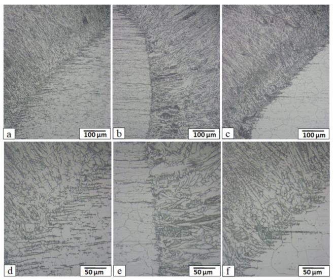
  • Columnar dendrite austenite grains with small arm spacing resulted in most of the welded fusion zones. The size of the dendrites became finer at lower heat input (lower power and faster speed). At higher heat input, reasonable amounts of lathy equiaxed grains with some delta ferrite occurred;
  • There was almost no HAZ in any of the weld joints. It consisted of an austenitic microstructure with some small amount of delta ferrite appearing at the grain boundaries, which prevented the crack formation during the welding;
  • Fusion zone hardness values for all the joints were significantly greater than that of the base alloy. The highest hardness was obtained in the case of the lower heat input sample (2000 W and 60 mm/s) and the lowest hardness was recorded corresponding to the highest heat input (2000 W and 20 mm/s);
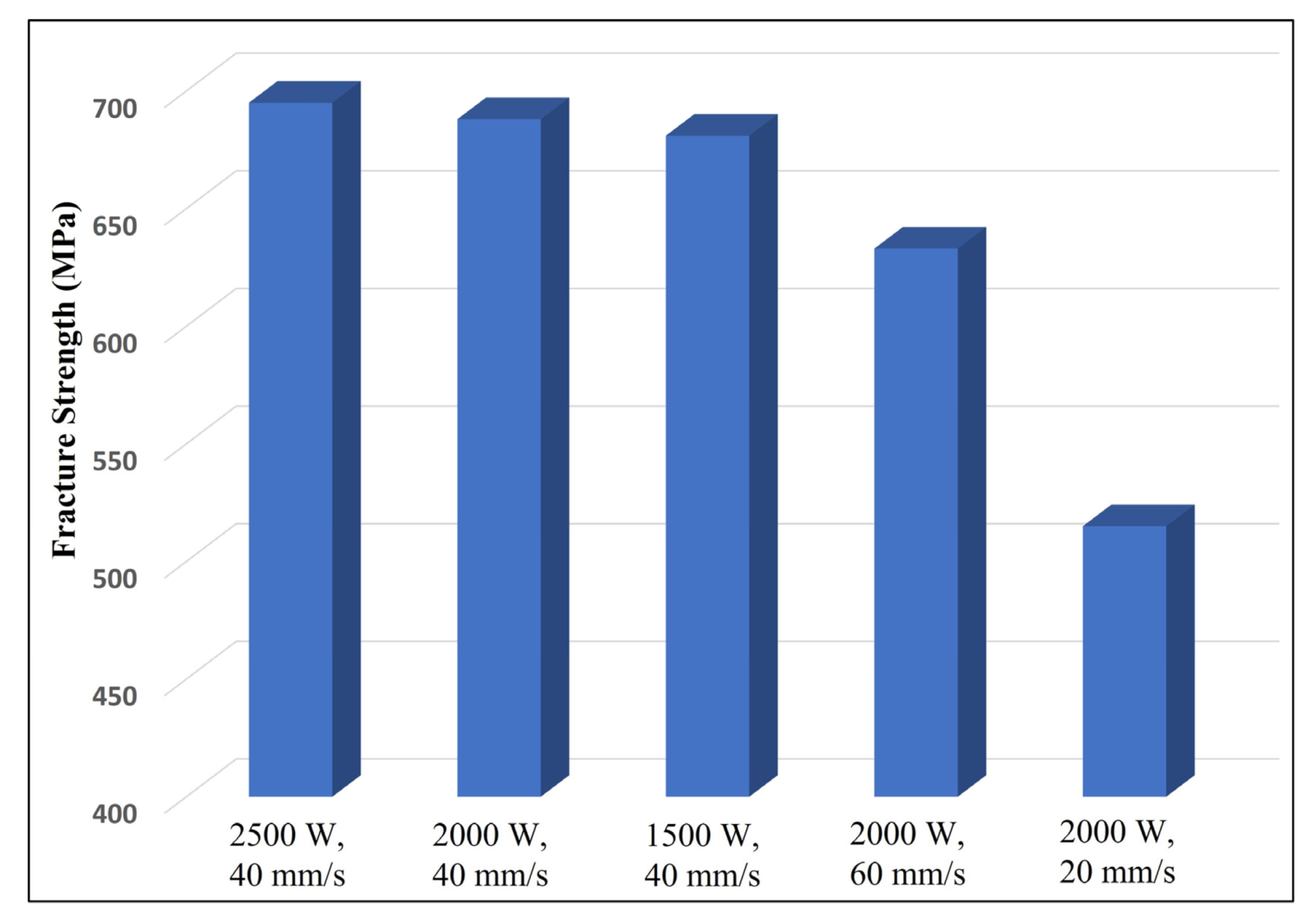
  • The fracture strength of the welded joints ranged from 97 to 72% of the base metal. It depends mainly on the welding heat input. Values close to the base alloy were attained at lower heat input without defects.

Author Contributions

Conceptualization, E.R.I.M.; methodology, E.R.I.M. and H.A.; software, M.A.E.; validation, A.A.; formal analysis, H.A. and A.A.; investigation, E.R.I.M.; resources, E.R.I.M.; data curation, A.A.; writing—original draft preparation, E.R.I.M.; writing—review and editing, A.A.; visualization, E.R.I.M.; supervision, H.A.; project administration, M.A.E.; funding acquisition, M.A.E. All authors have read and agreed to the published version of the manuscript.

Funding

This research received no external funding.

Acknowledgments

The authors extend their appreciation to the Deanship of Scientific Research at King Khalid University, Saudi Arabia for funding this work through General Research Group Program under Grant No: RGP. 2/108/42.

Conflicts of Interest

The authors declare no conflict of interest.

References

  1. Bahrami, A.; Taheri, P.A. Study on the Failure of AISI 304 Stainless Steel Tubes in a Gas Heater Unit. Metals 2019, 9, 969. [Google Scholar] [CrossRef] [Green Version]
  2. Kolli, S.; Javaheri, V.; Kömi, J.; Porter, D. On the Role of Grain Size and Carbon Content on the Sensitization and Desensitization Behavior of 301 Austenitic Stainless Steel. Metals 2019, 9, 1193. [Google Scholar] [CrossRef] [Green Version]
  3. Bell, S.; Steinberg, T.; Will, G. Corrosion mechanisms in molten salt thermal energy storage for concentrating solar power. Renew. Sustain. Energy Rev. 2019, 114, 109328. [Google Scholar] [CrossRef]
  4. Hurley, M.F.; Olson, C.R.; Ward, L.J.; Jaques, B.J.; Johnson, K.A.; Gunnerson, J.K.; Butt, D.P. Transgranular stress corrosion cracking of 304L stainless steel pipe clamps in direct use geothermal water heating applications. Eng. Fail. Anal. 2013, 33, 336–346. [Google Scholar] [CrossRef] [Green Version]
  5. Antoun, B.R.; Chambers, R.S.; Emery, J.M.; Tandon, R. Small Strain Plasticity Behavior of 304L Stainless Steel in Glass-to-Metal Seal Applications. Chall. Mech. Time-Depend. Mater. 2015, 2, 49–54. [Google Scholar] [CrossRef]
  6. Sun, C.; Zheng, S.; Wei, C.C.; Wu, Y.; Shao, L.; Yang, Y.; Hartwig, K.T.; Maloy, S.A.; Zinkle, S.J.; Allen, T.R.; et al. Superior radiation-resistant nanoengineered austenitic 304L stainless steel for applications in extreme radiation environments. Sci. Rep. 2015, 5, 7801. [Google Scholar] [CrossRef] [Green Version]
  7. Desu, R.K.; Krishnamurthy, H.N.; Balu, A.; Gupta, A.K.; Singh, S.K. Mechanical properties of Austenitic Stainless Steel 304L and 316L at elevated temperatures. J. Mater. Res. Technol. 2016, 5, 13–20. [Google Scholar] [CrossRef] [Green Version]
  8. Jo, B.; Okamoto, K.; Kasahara, N. Creep Buckling of 304 Stainless-Steel Tubes Subjected to External Pressure for Nuclear Power Plant Applications. Metals 2019, 9, 536. [Google Scholar] [CrossRef] [Green Version]
  9. Chen, Z.; Fang, Y.; Li, P.; Yu, Z.; Wu, X.; Li, D. Microstructure, Residual Stress and Mechanical Properties of a High Strength Steel Weld using Low Transformation Temperature Welding Wires. Mater. Des. 2015, 65, 1214–1221. [Google Scholar] [CrossRef]
  10. Chuaiphan, W.; Srijaroenpramong, L. Effect of welding speed on microstructures, mechanical properties and corrosion behavior of GTA-welded AISI 201 stainless steel sheets. J. Mater. Process. Technol. 2014, 214, 402–408. [Google Scholar] [CrossRef]
  11. Suresh, G.G.; Parida, P.K.; Bandi, S.; Ningshen, S. Effect of carbon content on the low temperature sensitization of 304L SS and its corrosion resistance in simulated ground water. Mater. Chem. Phys. 2019, 226, 184–194. [Google Scholar] [CrossRef]
  12. Yan, J.; Gao, M.; Zeng, X. Study on microstructure and mechanical properties of 304 stainless steel joints by TIG, laser and laser-TIG hybrid welding. Opt. Lasers Eng. 2010, 48, 512–517. [Google Scholar] [CrossRef]
  13. Costanza, G.; Sili, A.; Tata, M.E. Weldability of austenitic stainless steel by metal arc welding with different shielding gas. Procedia Struct. Integr. 2016, 2, 3508–3514. [Google Scholar] [CrossRef] [Green Version]
  14. Sathiya, P.; Mishra, M.K.; Shanmugarajan, B. Effect of shielding gases on microstructure and mechanical properties of super austenitic stainless steel by hybrid welding. Mater. Des. 2012, 33, 203–212. [Google Scholar] [CrossRef]
  15. Sakthivel, T.; Vasudevan, M.; Laha, K.; Parameswaran, P.; Chandravathi, K.S.; Mathew, M.D.; Bhaduri, A.K. Creep rupture strength of activated-TIG welded 316L(N) stainless steel. J. Nucl. Mater. 2011, 413, 36–40. [Google Scholar] [CrossRef]
  16. Niagaj, J. Influence of Activated Fluxes on the Bead Shape of A-TIG Welds on Carbon and Low-Alloy Steels in Comparison with Stainless Steel AISI 304L. Metals 2021, 11, 530. [Google Scholar] [CrossRef]
  17. Wegrzyn, T. Delta ferrite in stainless steel weld metals. Weld. Int. 1992, 6, 690–694. [Google Scholar] [CrossRef]
  18. Shankar, V.; Gill, T.P.S.; Mannan, S.L.; Sundaresan, S. Solidification cracking in austenitic stainless steel welds. Sadhana 2003, 28, 359–382. [Google Scholar] [CrossRef]
  19. Sharma, R.; Molian, P. Weldability of advanced high strength steels using an Yb:YAG disk laser. J. Mater. Process. Technol. 2011, 211, 1888–1897. [Google Scholar] [CrossRef]
  20. Parkes, D.; Westerbaan, D.; Nayak, S.S.; Zhou, Y.; Goodwin, F.; Bhole, S.; Chen, D.L. Tensile properties of fiber laser welded joints of high strength low alloy and dual-phase steels at warm and low temperatures. Mater. Des. 2014, 56, 193–199. [Google Scholar] [CrossRef]
  21. Li, G.; Zhang, C.; Gao, M.; Zeng, X. Role of arc mode in laser-metal active gas arc hybrid welding of mild steel. Mater. Des. 2014, 61, 239–250. [Google Scholar] [CrossRef]
  22. Soltani, H.M.; Tayebi, M. Comparative study of AISI 304L to AISI 316L stainless steels joints by TIG and Nd:YAG laser welding. J. Alloys Compd. 2018, 767, 112–121. [Google Scholar] [CrossRef]
  23. Gardner, L.; Bu, Y.; Theofanous, M. Laser-welded stainless steel I-sections: Residual stress measurements and column buckling tests. Eng. Struct. 2016, 127, 536–548. [Google Scholar] [CrossRef]
  24. Kumar, N.; Mukherjee, M.; Bandyopadhyay, A. Comparative study of pulsed Nd:YAG laser welding of AISI 304 and AISI 316 stainless steels. Opt. Laser Technol. 2017, 88, 24–39. [Google Scholar] [CrossRef]
  25. Tadamalle, A.P.; Reddy, Y.P.; Ramjee, E.; Reddy, V. Evaluation of Nd: YAG Laser Welding Efficiencies for 304L Stainless Steel. Procedia Mater. Sci. 2014, 6, 1731–1739. [Google Scholar] [CrossRef] [Green Version]
  26. Gnanasekaran, S.; Kumar, S.S.; Venugopal, N.; Upadhyaya, M.; Manjunath, T.C.; Chelladurai, S.S.J.; Padmanaban, G. Effect of laser power on microstructure and tensile properties of pulsed Nd:YAG laser beam welded AISI 301 austenitic stainless steel joints. Mater. Today Proc. 2021, 37, 934–939. [Google Scholar] [CrossRef]
  27. Saravanan, S.; Sivagurumanikandan, N.; Raghukandan, K. Effect of process parameters in microstructural and mechanical properties of Nd: YAG laser welded super duplex stainless steel. Mater. Today Proc. 2020, 39, 1248–1253. [Google Scholar] [CrossRef]
  28. Abdo, H.S.; Seikh, A.H.; Mohammed, J.A.; Uzzaman, T. Ameliorative Corrosion Resistance and Microstructure Characterization of 2205 Duplex Stainless Steel by Regulating the Parameters of Pulsed Nd:YAG Laser Beam Welding. Metals 2021, 11, 1206. [Google Scholar] [CrossRef]
  29. Li, Z.; Yu, G.; He, X.; Li, S.; Tian, C.; Dong, B. Analysis of surface tension driven flow and solidification behavior in laser linear welding of stainless steel. Opt. Laser Technol. 2020, 123, 105914. [Google Scholar] [CrossRef]
  30. Iamboliev, T.; Katayama, S.; Matsunawa, A. Interpretation of Phase Formation in Austenitic Stainless Steel Welds. Weld. Res. 2003, 82, 337S–347S. [Google Scholar]
  31. Meng, Y.; Li, G.; Gao, M.; Zeng, X. Effects of groove parameters on space constraint of narrow gap laser-arc hybrid welding. J. Manuf. Process. 2018, 33, 144–149. [Google Scholar] [CrossRef]
  32. Shin, W.; Son, B.; Song, W.; Sohn, H.; Jang, H.; Kim, Y.; Park, C. Heat treatment effect on the microstructure, mechanical properties, and wear behaviors of stainless steel 316L prepared via selective laser melting. Mater. Sci. Eng. A 2021, 806, 140805. [Google Scholar] [CrossRef]
Figure 1. (a) Optical microstructure of 304L stainless steel base metal and (b) enlarged image of (a).
Metals 11 02022 g001
Figure 2. Macrographs of the weld cross-sections with varying parameters, (a) 2500 W and 40 mm/s, (b) 2000 W and 40 mm/s, (c) 1500 W and 40 mm/s, (d) 2000 W and 60 mm/s, and (e) 2000 W and 20 mm/s.
Metals 11 02022 g002
Figure 3. Different magnified microstructures of the weld zone at a constant welding speed of 40 mm/s and different laser powers of: (a,d) 2500 W, (b,e) 2000 W, and (c,f) 1500 W.
Metals 11 02022 g003
Figure 4. Different magnified microstructures of the weld zone at a constant laser power of 2000 W and different laser welding speeds of: (a,d) 60 mm/s, (b,e) 40 mm/s, and (c,f) 20 mm/s.
Metals 11 02022 g004
Figure 5. Magnified SEM image of dendrites of weld zone produced at 2000 W laser power and 40 mm/s welding speed.
Metals 11 02022 g005
Figure 6. Different magnified microstructures of the HAZ at a constant welding speed of 40 mm/s and different laser powers of: (a,d) 2500 W, (b,e) 2000 W, and (c,f) 1500 W.
Metals 11 02022 g006
Figure 7. Different magnified microstructures of the HAZ at a constant laser power of 2000 W and different laser welding speeds of: (a,d) 60 mm/s, (b,e) 40 mm/s, and (c,f) 20 mm/s.
Metals 11 02022 g007
Figure 8. XRD pattern for the laser welded sample at: (a) power of 2000 W and welding speed of 60 mm/s, and (b) power of 2000 W and welding speed of 20 mm/s (γ: Austenite and ά: Ferrite).
Metals 11 02022 g008
Figure 9. Tensile fracture strength of the welded samples at different laser power and welding speeds.
Metals 11 02022 g009
Figure 10. Hardness measurements through the weld joints cross-sections for (a) different laser powers at a constant welding speed of 40 mm/s, and (b) different welding speed at a constant laser power of 2000 W.
Metals 11 02022 g010
Table 1. Composition of the 304L stainless steel base metal (wt. %).
CCrNiMoSiMnPSFe
0.02318.59.70.0070.550.120.020.008Bal.
Table 2. Mechanical properties of the 304L stainless steel base metal.
Hardness (HV)Ultimate Tensile Strength (MPa)Yield Strength (MPa)Elongation (%)
19271053239
Table 3. Welding conditions used for experimentation.
Specimen No.Power (W)Speed (mm/s)Net Heat Supplied (J/mm)
#125004062.5
#220004050
#315004037.5
#420006033.3
#5200020100
Table 4. Weld joint width results.
Specimen No.Top (mm)Center (mm)Bottom (mm)
#11.731.032.7
#21.90.922.65
#31.350.751.73
#41.310.631.52
#51.762.032.89
Publisher’s Note: MDPI stays neutral with regard to jurisdictional claims in published maps and institutional affiliations.

