Article

Effect of Alloying on the Nucleation and Growth of Laves Phase in the 9–10%Cr-3%Co Martensitic Steels during Creep

Laboratory of Mechanical Properties of Nanostructured Materials and Superalloys, Belgorod National Research University, Pobeda 85, 308015 Belgorod, Russia
*
Author to whom correspondence should be addressed.
Metals 2021, 11(1), 60; https://doi.org/10.3390/met11010060
Submission received: 5 December 2020 / Revised: 25 December 2020 / Accepted: 26 December 2020 / Published: 30 December 2020
(This article belongs to the Special Issue Creep and Deformation of Metals and Alloys at Elevated Temperatures)

Abstract

:
Five Co-modified P92-type steels with different contents of Cr, W, Mo, B, N, and Re have been examined to evaluate the effect of the chemical composition on the evolution of Laves phase during creep at 650 °C. The creep tests have been carried out at 650 °C under various applied initial stresses ranging from 80 to 200 MPa until rupture. An increase in the B and Cr contents leads to a decrease in the size and volume fraction of M23C6 carbides precipitated during tempering and an increase in their number particle density along the boundaries. In turns, this affects the amount of the nucleation sites for Laves phase during creep. The (W+Mo) content determines the diffusion growth and coarsening of Laves phase during creep. Susceptibility of Laves phase to coarsening with a high rate is caused by the large difference in Gibbs energy between fine and large particles located at the low-angle and high-angle boundaries, respectively, and can cause the creep strength breakdown. The addition of Re to the 10%Cr steel with low N and high B contents provides the slowest coarsening of Laves phase among the steels studied.

1. Introduction

Creep resistant 9–12%Cr martensitic steels are widely used as materials for fossil power plants operating at temperatures up to 620 °C [1,2]. Superior creep resistance of these steels is attributed to the (a) formation of 100% tempered martensite lath structure during heat treatment and (b) retaining of this structure for a long time under the action of the elevated temperature and applied stress [1,2,3,4,5,6]. The stability of the tempered martensite lath structure is provided by the stability of secondary phase particles such as the boundary M23C6 carbides and Laves phase particles and MX carbonitrides randomly distributed in the matrix [1,2,3,4,5,6,7,8,9,10,11,12,13,14,15,16,17,18,19,20]. Among these secondary phase particles, the role of Laves phase in the creep resistance of high-chromium steels is mostly ambiguous [2,3,4,8,21,22,23,24,25,26,27,28,29,30,31,32,33,34,35,36,37,38,39,40,41,42,43,44,45]. On the one hand, the precipitation of fine Laves phase particles produces additional dispersion strengthening [17,20,21,23,24,28,32,33,34,35,36], which decreases the creep rate in the transient creep region and the minimum steady-state creep rate as well as induces a high threshold stress [6,17]. The chains of Laves phase induce a high Zener drag force, preventing migration of the lath boundaries, and provide the stability of the tempered martensite lath structure under creep conditions [6,17,32], that compensates for the depletion of W and Mo atoms from the solid solution. On the other hand, the fast growth of Laves phase promotes an increase in the creep rate and premature failure [2,3,16,18,22,25,26,37,39,40,41]. Coarse Laves phase particles located at the boundaries of prior austenite grains (PAGs) act as cavity nucleation sites initiating premature damage that decreases the strain to rupture [25]. The nucleation of Laves phase in the 9–12%Cr steels takes place at the boundaries of PAGs and martensitic laths [2,3,4,8,21,22,23,24,25,26,27,28,29,30,31,32,33,34,35,36,37,38,39,40,41,42,43,44,45] as well as in the vicinity of M23C6 carbides [42,43]. The aim of the present research is to report on the effect of the chemical composition of the Co-modified 9–10%Cr martensitic steels on the evolution of Laves phase during creep as well as to establish the role of Laves phase in the creep strength breakdown appearance.

2. Materials and Methods

Five Co-modified P92-type steels with different Cr, W, Mo, B, N, and Re contents denoted here as the 9Cr2W0.005B, 9Cr3W0.005B, 9Cr1.5W0.012B, 10Cr2W0.008B, and 10Cr3W0.008B0.2Re steels were examined. The 9Cr2W0.05N and 9Cr3W0.05N steels with conventional N and B contents were produced by air melting [29,31,32]; the 9Cr1.5W0.007N, 10Cr2W0.003N, and 10Cr3W0.002N0.2Re steels with low N (≤0.007%) and high B contents (≥0.008%) were melted in vacuum-induction furnaces [6,17,18,19,20,27,28,30]. The chemical compositions of these steels, determined using a FOUNDRY-MASTER UVR optical emission spectrometer (Oxford Instruments, Ambingdon, UK), a METEK-300/600 nitrogen, hydrogen, and oxygen analyzer (METEKPROM Ltd., Izhevsk, Russia), and a Nova NanoSEM scanning electron microscope (FEI, Hillsboro, OR, USA) with an energy dispersive X-ray spectroscope (Oxford Instruments, Ambingdon, UK), are summarized in Table 1.
These steels studied were subjected to homogenization annealing at 1100–1150 °C for 16 h and then hot forged in the temperature interval ranging from 1150 to 1050 °C. The heat treatment of the steels consisted in normalizing at 1050–1060 °C for 30–60 min, air cooling, and final tempering at 750–770 °C for 3 h [6,16,17,18,19,20,27,28,29,30,31,32]. Creep tests were carried out in the air at 650 °C under various applied initial stresses ranging from 80 to 200 MPa with a step of 20 MPa until rupture for all steels and under 120 MPa for 1000 h (interrupted tests) for the 10Cr2W0.008B and 10Cr3W0.008B0.2Re steels.
An Olympus GX70 optical microscope (Olympus Corporation, Tokyo, Japan) was used to reveal the PAG boundaries by etching of grounded and polished samples in the solution of 2 pct HNO3 and 1 pct HF in distilled water. A JEOL–2100 transmission electron microscope (TEM) (JEOL Ltd., Tokyo, Japan) with an INCA energy dispersive X-ray spectroscope (EDS) (Oxford Instruments, Ambingdon, UK) and Nova NanoSEM and Quanta 600FEG scanning electron microscopes (SEM) (FEI, Hillsboro, OR, USA) were used for the structural characterization of the tempered and ruptured/interrupted creep specimens. The samples for TEM and SEM investigations (foils and carbon replicas) were prepared from a gauge section of ruptured crept specimens in the middle between grip portion and fracture surface. Foils for TEM and SEM were obtained by electropolishing at room temperature using a Struers “TenuPol-5” machine (Struers Inc., Cleveland, OH, USA). Carbon replicas for TEM were prepared using a Q 150REQuorum vacuum deposition machine (Quorum Technologies, Laughton, UK). The average size of subgrains was estimated on TEM micrographs by the linear intercept method. The dislocation density in the lath interiors was evaluated as a number of intersections of individual dislocations with foil surfaces per unit area on at least five selected typical TEM images for each data point. The size distribution and mean size of the precipitates were evaluated by counting from 100 to 150 particles per specimen. The error bars were given according to the standard deviation. The number particle density was estimated as the number of particles of Laves phase per unit length of high-angle boundary (HAB) on at least five selected typical SEM images and of low-angle boundary (LAB) on at least five selected typical TEM images. Identification of secondary phase particles was based on a combination of EDS composition measurements and indexing of electron diffraction patterns by TEM. The equilibrium volume fraction of Laves phase at 750, 770, and 650 °C was obtained using the Thermo-Calc software (Version 5.0.4 75, Thermo-Calc software AB, Stockholm, Sweden, 2010). Other details of mechanical and structural characterization techniques were presented in the previous studies [6,16,17,18,19,20,27,28,29,30,31,32].

3. Results

3.1. Tempered Martensite Lath Structure

The formation of the tempered martensite lath structure was observed in all steels studied (Figure 1). The structural parameters of the steels are summarized in Table 2. The average size of PAGs, dPAG, varied in the range of 10–50 μm and tended to increase with the following changes in the chemical composition (Table 1 and Table 2):
-
with increasing the W content (from 2% to 3%)—dPAG increased from 10 μm for the 9Cr2W0.005B steel to 20 μm for the 9Cr3W0.005B steel;
-
with decreasing the N (to 0.007%) and increasing the B (to 0.012%) contents—dPAG increased to 26 μm (the 9Cr1.5W0.012B steel);
-
with increasing the Cr content (to 10%) together with decreasing the N (0.003%) and increasing the B (0.008%) contents—it increased to 35 μm (the 10Cr2W0.008B steel);
-
with the addition of Re and an increase in the W content—dPAG increased to 51 μm (the 10Cr3W0.008B0.2Re steel).
The typical tempered martensite lath structure of the 9–10%Cr-3%Co martensitic steels [16,32] is shown in Figure 1a using the example of the 9Cr2W0.005B steel. The mean lath thickness of ~0.3–0.4 μm and the high density of free dislocations of ~2 × 10¹⁴ m−2 were essentially the same for all steels (Table 2). Nanoscale M23C6 carbides with round shape, which were the dominant precipitates in all steels studied, were located along the PAG/packet/block and lath boundaries, while their mean size decreased from 90 to 70 nm with increasing the B content (Table 2). The number particle densities of boundary M23C6 carbides located at the HABs and LABs were 1.41 and 0.94 μm−1, respectively, in the steels with conventional B contents. In the steels with conventional N content, MX carbonitrides were divided into V-rich particles with a plate-like shape and Nb-rich particles with a round shape; these particles with an average dimension of 30 nm were randomly distributed in the ferritic matrix; their volume fraction was 0.34% (Table 2).
Changes in the W, Cr, N, B, and Re contents led to the structural changes presented in Figure 1b as follows:
(1)
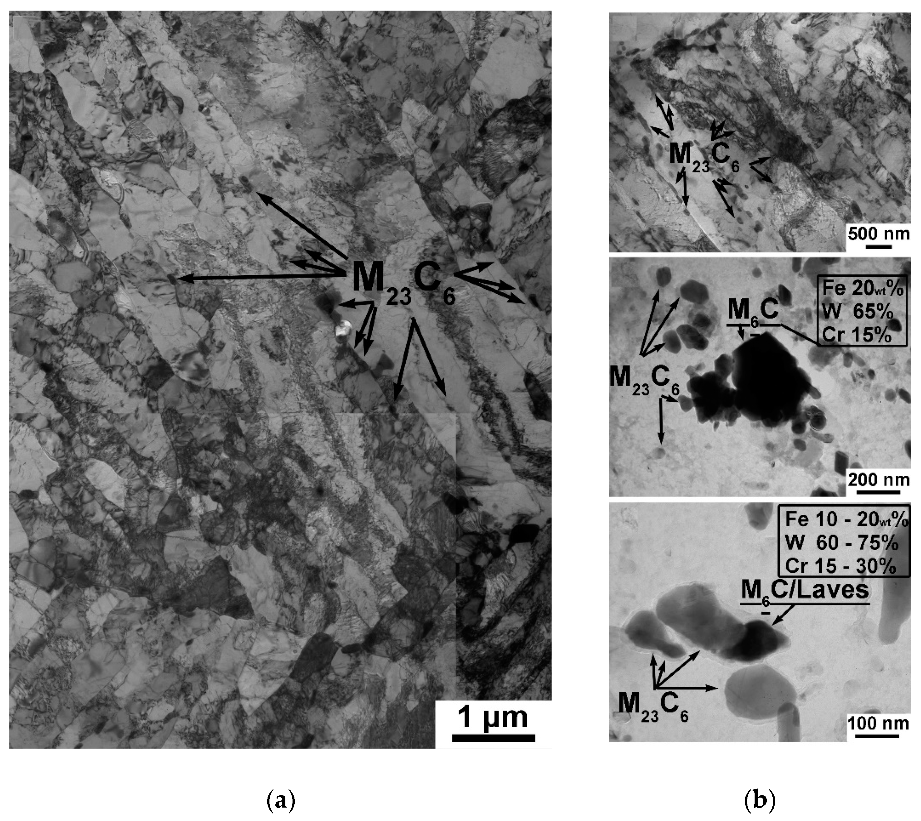
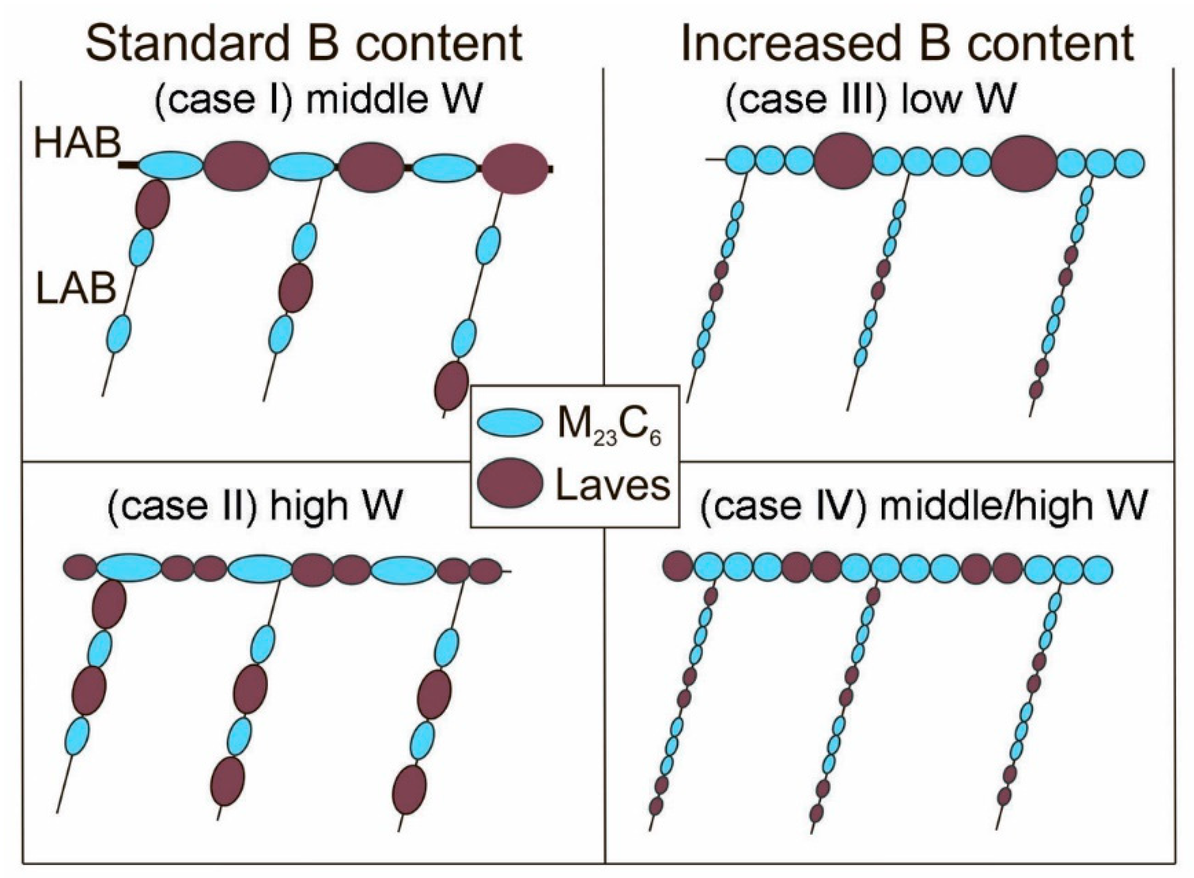
decreasing the N and increasing the B contents increased the number particle density of M23C6 carbides at both HABs and LABs together with decreasing their mean size and volume fraction (Figure 1b and Table 2). In the 9%Cr and 10%Cr steels with low N and high B contents, the high number particle density along the HABs led to the formation of the continuous chains of M23C6 carbides (Figure 1b) that affected the number of nucleation sites for precipitation of Laves phase during creep;
(2)
increasing the W and Cr contents led to the formation of W-rich particles such as M6C carbides in the 9Cr3W0.005B, 10Cr2W0.008B, and 10Cr3W0.008B0.2Re steels and/or even Laves phase in the 9Cr3W0.005B steel (Figure 1b) [30,31]. In all steels, the amount of W-rich particles was negligible. It was found that the M6C carbides in the 9%Cr steel were coarse (350 nm), whereas in the 10%Cr steels, the fine particles (25–30 nm) were found along the LABs (Figure 1b and Table 2);
(3)
in the steels with a low N content, the volume fraction of MX carbonitrides decreased significantly (0.04…0.08%) due to the low fraction or full disappearance of V-rich MX phase in the tempered steels and the shape of V-rich particles changed from plate-like to round [17,18,19,20].

3.2. Creep Tests

The creep conditions, rupture times, and duration of interrupted tests together with off-set time, at which the minimum creep rate is achieved, are presented in Table 3. The creep strength curves and the variation of the minimum creep rate with applied stresses are plotted in Figure 2. Almost all 9%Cr and 10%Cr steels exhibited the creep strength breakdown (CSB) regardless of the PAG size [17,19,27,28,32] (Figure 2a). No transition from short-term creep to long-term creep behavior was found for the 10Cr2W0.008B steel up to a rupture time of 39,437 h (Figure 2a and Table 3) [6,17]. For the 9Cr2W0.005B, 9Cr1.5W0.012B, and 10Cr3W0.008B0.2Re steels, the CSB appeared at 140 MPa that subdivided the creep behavior into three distinctly different regions: the region of short-term creep at the high applied stresses >140 MPa, the transition region at the applied stress of 140 MPa, and the region of long-term creep at the low applied stresses <140 MPa. For both 9%Cr steels with 1.5–2%W, the rupture time, at which the CSB took place, was similar ranging from 2000 to 3500 h, whereas the CSB for the 10%Cr steel with 3%W was observed at ~11,000 h (Figure 2a). Thus, an increase in the W content from 2 to 3 wt.% shifts the CSB to a lower applied stress of 120 MPa and a higher rupture time of ~ 11,000 h that correlates with the rupture time of the CSB for the 10Cr3W0.008B0.2Re steel (Figure 2a and Table 3).
Dependences between the minimum creep rate and applied stress for all steels studied obey a power law relationship [2,45,46]:
ε ˙ min = A × σ n * exp ( Q R T ) ,
where ε ˙ min is the minimum creep rate, σ is the applied stress, Q is the activation energy for steady-state creep, R is the gas constant, T is the absolute temperature, A is a constant, and n* is the “apparent” stress exponent. For the 9%Cr steels, an “apparent” stress exponent n* = 11…13, whereas for the 10%Cr steels, it was about 2 times higher and comprised 23…26 (Figure 2b). For the steels with 3%W and the 9Cr1.5W0.012B steel, at lower stresses, a linear dependence with a lower slope and n* = 3…6 was distinguished (Figure 2b). It should be noted that the stresses at which the change in the n* occurred (Figure 2b), correlated with the stresses at which the CSB occurred (Figure 2a).
The creep curves at the applied stress corresponding to the regions of high stresses (180 MPa), transient stress (140 MPa), and low stresses (120 MPa) are presented in Figure 3. Under the high applied stress of 180 MPa, the 9%Cr steels showed the better creep behavior than the 10%Cr steels (Figure 3). The 9Cr3W0.005B steel demonstrated the longest rupture time due to the lowest minimum creep rate and the longest primary creep stage, and the well-defined steady-state creep stage. This finding was associated with the highest W content in the solid solution. The 10Cr2W0.008B steel demonstrated the shortest rupture time due to the highest ε ˙ min among the steels studied. The addition of Re together with increasing the W and decreasing the Mo content (Table 1) decreased the ε ˙ min by almost an order of magnitude and increased rupture time (Figure 3 and Table 3).
Under the transient applied stress of 140 MPa, the Re-containing steel showed an advantage. It had the longest rupture time due to the elongated primary creep stage, the lowest ε ˙ min , and the well-defined steady-state creep stage (Figure 3). The lower N and higher B contents in the 9Cr1.5W0.012B steel led to an increase in the off-set time and a decrease in the off-set strain, at which the ε ˙ min was attained, compared with the 9Cr2W0.005B steel with conventional N and B contents.
Under the low applied stress of 120 MPa, creep behavior of the 10Cr2W0.008B steel fundamentally differed from other 9–10%Cr steels: the longest primary creep stage and the lowest ε ˙ min provided a uniquely long rupture time and absence of the CSB up to ~40,000 h (Figure 2a, Figure 3, and Table 3). Other steels had the similar creep behavior, although the steels with 3%W demonstrated the slight increment in the duration of the primary creep stage and a decrease in the ε ˙ min (Figure 3 and Table 3).

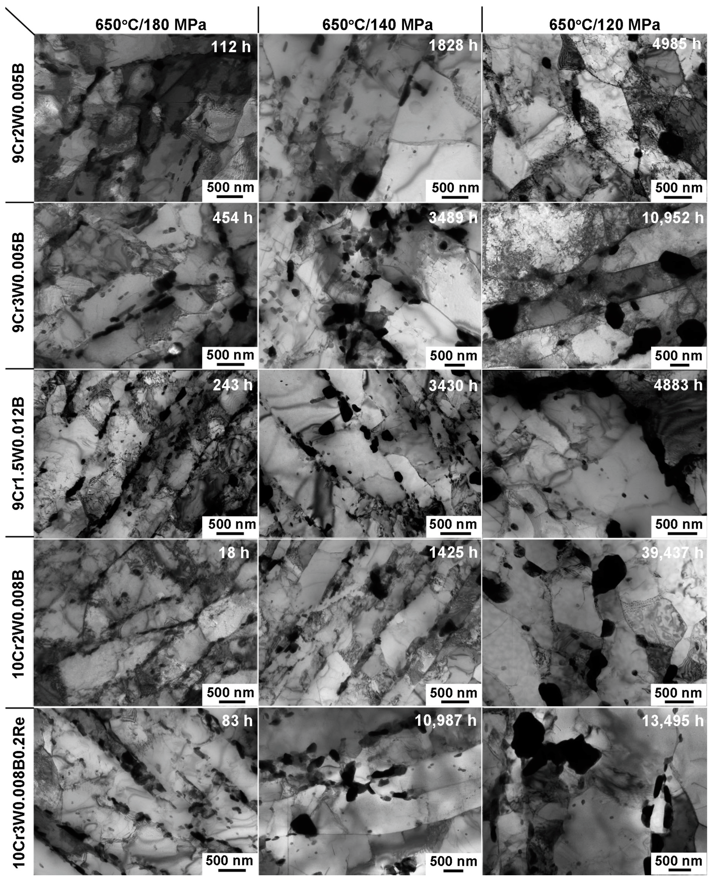
3.3. Crept Microstructures

SEM-back scattered electron (BSE) images and TEM images of all steels studied after some creep rupture tests corresponding to a region of short-term creep at the high applied stress of 180 MPa, a transition region at the applied stress of 140 MPa and a region of long-term creep at the applied stress of 120 MPa are shown in Figure 4 and Figure 5. The structural parameters of these ruptured specimens are summarized in Table 4.
The structures of all steels studied were significantly different in the regions of short-term and long-term creep (Figure 4 and Figure 5). In the short-term creep region, at the high applied stress (180 MPa), the tempered martensite lath structure retained, while first subgrains appeared. The average lath thickness increased by a factor of ~2 and the dislocation density decreased twice compared to the tempered state. The mean size of M23C6 carbides increased insignificantly and fine particles of Laves phase precipitated along the HABs and LABs (Figure 4 and Figure 5, and Table 4). As a result, continuous chains of M23C6 carbides and Laves phase occurred along the PAG boundaries (Figure 4). Decreasing the N content and increasing the B content provided a high particle density along the lath boundaries (Figure 5). In the regions of the transition and low applied stresses (140 and 120 MPa), the tempered martensite lath structure evolved into the subgrain structure, the mean size of subgrains was comparable with the width of the martensitic laths (Figure 4 and Figure 5, and Table 4). The boundary particles coarsened (Figure 4 and Figure 5, and Table 4).

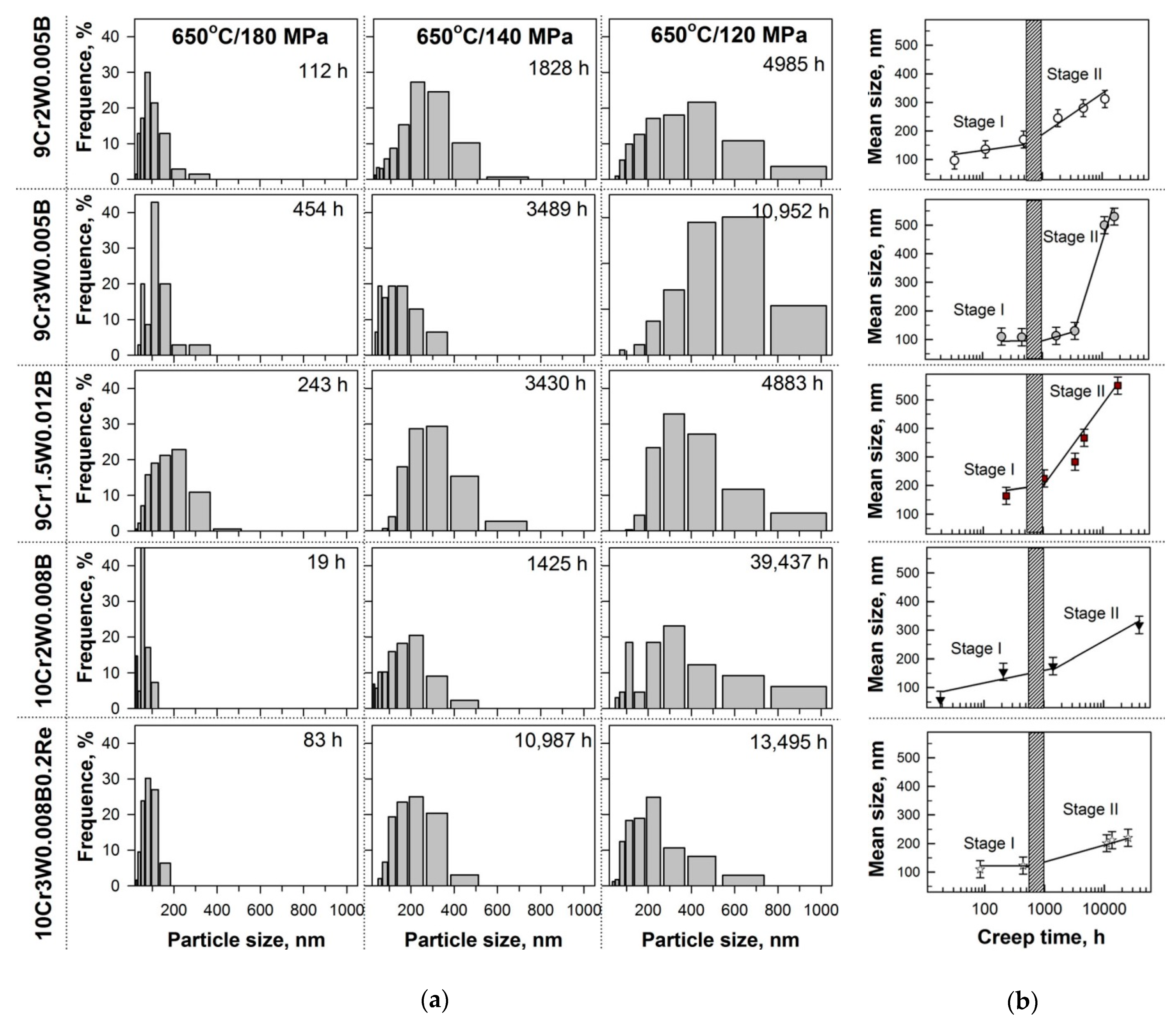
3.4. Evolution of Laves Phase during Creep

Change in the W content in the ferritic matrix during creep. A significant difference between the crept microstructure and initial structure after tempering was the reduced W content in the ferritic matrix and the precipitation of Laves phase as the related processes. Figure 6 demonstrates two stages of the depletion of W from the solid solution with creep time that is independent of material chemistry. During the first 500–1000 h of creep, the depletion of excess W from the solid solution occurred. Then, an equilibrium content of W in the solid solution was attained, that comprised about 1 wt%. for all steels studied (Figure 6). The rupture occurred before and after the complete depletion of excess W from the solid solution in the region of short-term and long-term creep, respectively (Figure 2 and Figure 6, and Table 3). So, under short-term creep condition, the continuous precipitation of Laves phase took place up to rupture, whereas under long-term creep, the growth of the Laves phase particles occurred after full depletion of excess value of W from the solid solution.
Evolution of average size and size distribution of Laves phase during creep. Size distributions of Laves phase together with time dependence of the mean size of these particles in the different steels are presented in Figure 7. The different time to rupture at the same creep conditions for the 9–10%Cr-3%Co steels led to different amount of Laves phase in the crept ruptured samples. So, at 180 MPa, for the 9Cr2W0.005B, 10Cr2W0.008B, and 10Cr3W0.008B0.2Re steels with rupture times of 112, 18, and 83 h, respectively (Table 2), the presence of excess W solutes in ferrite correlated with the low number density of Laves phase (Figure 4, Figure 5 and Figure 6, and Table 3). A very narrow size distribution of Laves phase with a mean dimension of 56 nm was observed in the 10Cr2W0.008B steel due to their precipitation in the vicinity of M23C6 carbides located on the lath boundaries [6] (Figure 5 and Figure 7a).
At the same time, in the 9Cr2W0.005B steel, the size distribution was broader than that in the 10Cr3W0.008B0.2Re steel due to a dominance of nucleation of Laves phase on the boundaries of the PAGs and packets after the similar creep time. Moreover, in the 9Cr2W0.005B steel, the large particles with sizes of 200–375 nm were observed, their fraction was about 5% (Figure 7a). For the 9Cr3W0.005B and 9Cr1.5W0.012B steels with rupture times of 243 and 454 h, respectively (Table 2), the amount of excess W solutes in the matrix was close to the equilibrium value and the nucleation of the Laves phase particles and their diffusion growth were almost completed (Figure 4, Figure 5 and Figure 6). Their volume fraction was close to the equilibrium value estimated by the Thermo-Calc software (Table 4). The onset of diffusion growth of Laves phase was found in these steels under short-term creep that led to a high portion of coarse particles of Laves phase in the 9Cr1.5W0.012B steel. In the last steel, there were 10% of coarse particles (275–500 nm), whereas in the 9Cr3W0.005B steel, about 90% of particles were ranging from 50 to 200 nm and 10% of particles were ranging from 200 to 375 nm. Therefore, the dominant precipitation of Laves phase on the boundaries of PAGs and packets leads to the appearance of coarse particles even under short-term creep.
At 140 MPa, the 9Cr3W0.005B steel also demonstrated the higher coarsening resistance of Laves phase in comparison with the steel with lower W content (9Cr1.5W0.012B), over the same time. The size distribution for the 9Cr1.5W0.012B steel was shifted to larger sizes and the mean size of Laves phase particles was about two times higher in comparison with that for the 9Cr3W0.005B steel. The formation of coarse Laves phase particles with a size more than 500 nm was observed in the 9Cr2W0.005B and 9Cr1.5W0.012B steels (Figure 4 and Figure 5, and Figure 7a). The Re-containing steel showed the narrowest size distribution evidencing for the most coarsening resistance of Laves phase after long-term creep for 10,987 h.
At 120 MPa, the coarsening of the Laves phase particles took place in all steels (Figure 4 and Figure 5, and Figure 7a). The fraction of coarse Laves phase particles larger than 500 nm attained approximately 15% in the 9Cr2W0.005B and 9Cr1.5W0.012B steels after ~5000 h exposure (Figure 7a). In the 3%W steel with conventional N and B contents, an intensive coarsening resulted in the appearance of 50% of large particles after ~11,000 h creep. In the Re-containing 3%W steel, the minimum fraction of large Laves phase particles (2%) was observed after long-term creep for 13,495 h.
The time dependences of the mean size of Laves phase particles presented in Figure 7b correspond to the depletion of W from the solid solution (Figure 6) and can be subdivided into two stages for all steels. Stage I corresponds to the first region, which reflects the depletion of excess W solutes from the solid solution, and is characterized by a weak slope of the curve (Figure 7b). The main processes at this stage were the formation of nuclei of Laves phase along the HABs and LABs and their diffusion growth due to the sedimentation of excess W solutes from the matrix.
At the end of stage I, the HABs played a role of the preferential nucleation sites for Laves phase (Figure 8 and Table 5). This is a common feature for all steels studied. The fraction of Laves phase on the HABs and LABs was estimated using SEM and TEM images after 454–1037 h of creep (Table 5), and, therefore, these portions corresponded to the termination of depletion of excess W solutes from the matrix and the attainment of the equilibrium value of W in the solid solution. The onset of coarsening of Laves phase occurred at higher creep times. It was revealed that in the steels with a high B content, the fraction of Laves phase located at the LABs was higher than that in the steels with a conventional B content (Figure 8 and Table 5). The mean size of the Laves phase particles located at the HABs was higher than that of located at the LABs in all steels studied excepting the 9Cr3W0.005B steel (Table 5).
Stage II of Laves phase evolution (Figure 7b) corresponds to the second stage of W depletion, at which an equilibrium W content in the solid solution is attained, and is characterized by intense growth of particles. At this stage, Ostwald ripening occurred which consisted in the coarsening of large particles due to the dissolution of fine particles [47,48,49]. Stage II can be described using Lifshitz–Slyozov–Wagner (LSW) relationship [50,51]:
dmd0m =Kp(tt0),
where d is the average particle size at a time of t, d0 is the average particle size at the time of t0 corresponding to the onset of the coarsening process, and Kp is the coarsening rate constant; the growth exponent m depends on the coarsening mechanism. The value m = 4 corresponding to grain boundary diffusion provided the best fit of the experimental data with linear dependences (Figure 9) for all steels studied, and, therefore, Ostwald ripening of Laves phase was controlled by grain boundary diffusion [28]. The time t0 was considered to be 1000 h for all steels, and d0 was taken from Figure 7b as the mean particle size at the time of t0. The highest coarsening rate of Laves phase was observed for the 9Cr3W0.005B and 9Cr1.5W0.012B steels, which had the biggest (2.05 wt.%) and the smallest (1.35 wt.%) value of molybdenum equivalent (Moeq = (Mo) + 1/2(W) [8]), respectively, among the steels studied. The coarsening rate constant was about 1.55 × 10⁻⁹ μm4 s−1 for both steels (Figure 9b). The lowest growth of Laves phase was revealed in the 10Cr3W0.008B0.2Re steel with a Moeq value of 1.55 wt%; the coarsening rate constant was two orders of magnitude lower than that of the 9Cr3W0.005B and 9Cr1.5W0.012B steels (Figure 9). The 9Cr2W0.005B and 10Cr2W0.008B steels with the Moeq values of 1.4 and 1.7 wt.%, respectively, demonstrated the similar coarsening rate constant for Laves phase of (1.3−2.1) × 10−10 μm4 s−1 (Figure 9a).

4. Discussion

4.1. Effect of Alloying on the Nucleation and Growth of Laves Phase

The results obtained on the evolution of W-rich Laves phase during creep in five 9–10%Cr-3%Co advanced martensitic heat-resistant steels with various alloying evidence that not only the W content but also other elements affect the Laves phase growth and, consequently, creep behavior. As it is known, the nucleation and growth of the Laves phase particles depend on the nucleation sites and the presence of substitutional elements retarding diffusion in ferrite [21,23,25,27,28,35,37,38,42,43]. The different size of PAGs for the steels studied (Table 2) partially affects the amount of nucleation sites for Laves phase precipitated along the HABs. So, in the 9 and 10%Cr steels with 2%W, an increase in the PAG size from 10 to 35 µm (Table 2) leads to a decrease in the number particle density from 2.50 to 1.56 µm−1, respectively (Table 5). On the other hand, since Laves phase precipitates at the boundaries, then the dispersion of boundary M23C6 carbides determines the nucleation behavior of Laves phase [42,43]. Let us consider the effect of these two factors (W content and dispersion of carbides) on the Laves phase evolution during creep. The effect of the PAG size is not considered in the present investigation.
Effect of dispersion of M23C6 carbides on the nucleation sites for Laves phase. The scheme describing the effect of the dispersion of M23C6 carbides on the nucleation of Laves phase in the steels with different alloying is suggested (Figure 10). It can be seen that in the steels with a conventional 0.005% B content, sparsely located M23C6 carbides along the HABs and LABs provide the most part of the boundaries as a ready-to-use substrate for the nucleation of Laves phase. The formation of W segregations in the vicinities of the HABs during tempering facilitates the precipitation of these particles [31]. The high (0.008–0.012%) B content in the 9–10%Cr-3%Co steels leads to a decrease in the size of M23C6 carbides because of the formation of M23(C,B)6 particles [16,17,18,19,20]. As a result, the number particle density of M23C6 carbides along both HABs and LABs is sufficiently higher as compared with steels with the conventional B content (Table 2 and Figure 10). Dense chains of M23C6 carbides cover the surface of the HABs that hinders the sedimentation of excess W solutes from the matrix on these boundaries and, correspondingly, the nucleation of the Laves phase particles, wherein W atoms segregate near the HABs as in a case of the steels with the conventional B content (Figure 6 and Figure 10). The W atoms from the segregation are redistributed between HABs and LABs forming the nuclei of Laves phase on the sites of the lath boundaries free of M23C6 carbides. As a result, the ratio of the Laves phase particles located at the HABs and LABs is changed in the B-enriched steels (Figure 8 and Table 5). The fraction of the Laves phase particles located at the LABs is higher and reaches 35% of all particles after Stage I (Figure 7, Figure 8 and Figure 9, and Table 5) that provides an effective anchorage of lath/subgrain boundaries by boundary particles during creep and highly decreases the minimum creep rate [6,19,21,38].
Effect of (W+Mo) content on the growth of Laves phase in steels with different B content. The (W+Mo) content in the steels determines the size of the Laves phase particles during diffusion growth. At the same time, the coarsening of particles is determined by the difference in Gibbs energy between coarse and fine particles [29,47,48,49]. It should be noted that most of the W atoms segregate towards the HABs in all 9–10%Cr steels that provides a high concentration of W atoms around the nucleus located at the HABs. The distribution of Laves phase before its coarsening in the steels studied can be presented by four combinations of the amount of nucleation sites for Laves phase particles at the HABs and LABs and the (W+Mo) content (Figure 10). They are the following:
(Case I) numerous nucleation sites at the HABs and a few nucleation sites at the LABs together with the low/middle (W+Mo) content (the 9Cr2W0.005B steel). In this case, large Laves phase particles are formed at both HABs and LABs (Figure 10). The average size of particles located at the HABs and LABs is similar (Table 5). The absence of a significant difference in the size of the particles located at the HABs and LABs provides a continuous coarsening of Laves phase with a moderate rate (Figure 7b and Figure 9).
(Case II) numerous nucleation sites at the HABs and a few nucleation sites at the LABs together with the high (W+Mo) content (the 9Cr3W0.005B steel). In this case, the Laves phase particles located at the HABs are fine, whereas particles located at the LABs are large (Table 5 and Figure 10). The dissolution of the particles located at the LABs is restricted because their Gibbs energy is lower than that of the particles located at the HABs. No coarsening takes place after the termination of diffusion growth (Figure 6 and Figure 7b). This fact indicates that coarsening of the Laves phase particles starts along the HABs until the sizes of the particles located at the HABs and LABs attain the comparable values. Then, the particles located at the LABs begin to dissolve, which accelerates the growth of Laves phase at the HABs [29]. This finding explains the stabilization of size of Laves phase for about 3500 h of creep and the following fast growth after 3500 h of creep (Figure 7b and Figure 9).
(Case III) moderate amount of nucleation sites at the HABs and many nucleation sites at the LABs together with the low (W+Mo) content (the 9Cr1.5W0.012B steel). In this case, large particles are located at the HABs and fine particles are located at the LABs (Table 5 and Figure 10). The appearance of coarse particles of Laves phase with a dimension ≥200 nm on the HABs initiates the dissolution of fine particles located at the LABs, increasing the difference in Gibbs energy between coarse particles at the HABs and fine particles at the LABs, which creates the big driving force for coarsening. This leads to the fast coarsening of Laves phase immediately when the diffusion growth has been completed (Figure 7b and Figure 9).
(Case IV) moderate amount of nucleation sites at the HABs and many nucleation sites at the LABs together with the middle/high (W+Mo) content (the 10Cr2W0.008B and 10Cr3W0.008B0.2Re steels). In this case, fine Laves phase particles are formed at both HABs and LABs (Table 5 and Figure 10) that provides the significant stability of this phase and continuous coarsening of Laves phase with a moderate/low rate (Figure 7b and Figure 9). This case is close to the case (I) that provides the similar coarsening rate constant of Laves phase in the 10Cr2W0.008B and 9Cr2W0.005B steels (Figure 9). The addition of Re to the 10%Cr steel with a low N and a high B contents slows down the diffusion of W atoms and hinders their redistribution along the boundaries during coarsening of Laves phase. This provides a decrease in the coarsening rate constant value by one order of magnitude as compared with the 10Cr2W0.008B steel (Figure 9). It should be noted that Re does not affect the diffusion growth of Laves phase, since the initial size of Laves phase before coarsening (1000 h of creep) is similar for both 10Cr3W0.008B0.2Re and Re-free 10Cr2W0.008B steels (Table 5). This finding may be associated with that the Re also segregates toward the boundaries before the onset of the coarsening of Laves phase. Moreover, M6C carbides precipitated along the LABs during creep and then transformed into Laves phase [30] can insignificantly increase the fraction of Laves phase located at the LABs (Figure 8 and Table 5).
Thus, the lowest rate of Laves phase coarsening takes place in steels with the high B content and dense chains of M23C6 carbides on the lath boundaries. Solutes inhibiting diffusion in ferrite also decrease the coarsening rate of Laves phase.

4.2. Relation between Coarsening of Laves Phase and CSB Appearance

The CSB appearance in the 9–12%Cr steels is the topic of actual discussion in the scientific research [2,8,9,10,11,12,13,14,15,16,19,32,45]. The most popular explanations of this phenomenon are related to the formation of large Z-phase particles instead of fine MX carbonitrides [9,11,12,13,14,15] and the strain-induced coarsening of M23C6 carbides facilitating the detachment of the lath boundaries from these particles [10,32]. Inspection of the experimental results shows that the dissolution of fine particles of Laves phase located at the LABs may result in the CSB if the density of M23C6 carbides on the lath boundaries is low under creep conditions [6,16,17,18,19,20,27,28,32]. In the steels with a conventional B content, the coarsening of M23C6 and Laves phase particles leads to a decrease in their number density along both HABs and LABs. M23C6 carbides located at the LABs also coarse quickly after the depletion of excess W content from the solid solution [16,32], whereas M23(C,B)6 particles are able to withstand to coarsening for a long time in the steels with high B content [6,17,18,19,20]. A lower number particle density causes a lower Zener pinning pressure exerted by M23C6 and Laves phase. When an overall pinning pressure falls below 0.08 MPa, a complete transformation of the tempered lath structure into the subgrain structure occurs followed by the subgrain growth under creep conditions [32]. Therefore, this structural evolution can be the reason for the CSB appearance.
A decrease in the number particle density of Laves phase along the LABs has different effect on the stability of the tempered martensite lath structure depending on the coarsening resistance of M23C6 carbides. So, in the steels with a conventional B content, the mutual growth of Laves phase particles and M23C6 carbides provokes the transformation of the lath structure into subgrain one [29,32], whereas in the steels with a high B content, the low number particle density of Laves phase due to their dissolution on lath boundaries is compensated by the high number particle density of M23(C,B)6 carbides resistant to coarsening [6,17,18,19,20]. High creep resistance of the 10Cr2W0.008B steel is provided by M23C6 carbides, which are very resistant to coarsening [6,17].
On the other hand, very large Laves phase particles with a dimension ≥500 nm can serve as nucleation sites for large voids and cracks [19,35,37,39,40] even if the tempered martensite lath structure retains, which is stabilized by fine M23(C,B)6 particles located on the LABs. This structure was observed in the 9Cr1.5W0.012B steel after creep test at 120 MPa for 4883 h, where Laves phase with a large mean size of 367 nm and the presence of 15% of coarse Laves phase particles larger than 500 nm were revealed (Figure 7), while M23C6 carbides were sufficiently small (114 nm). Fracture surface of the specimens tested at the applied stress of 120 MPa is shown in Figure 11. The overall dimple fracture is typical for surface of crept samples. However, very large dimples attributed to the growth and coalescence of particle-nucleated microvoids on coarse Laves phase particles are observed (Figure 11). The similar fracture surfaces are observed for the 9Cr3W0.005B steel after creep rupture tests at applied stresses of 120 and 100 MPa (not shown here). In this steel, the fraction of coarse Laves phase particles larger than 500 nm reaches 50% (Figure 7a). It should be noted that the formation of particle-nucleated microvoids and cracks leads to a decrease in the elongation to rupture under low applied stresses (Figure 3).
Comparison of Figure 2 and Figure 3, Figure 7b and Table 3 and Table 4 shows that the fast coarsening of Laves phase in the 9Cr3W0.005B and 9Cr1.5W0.012B steels takes place after about 3000 and 1000 h, respectively, that correlates to the termination of steady-state creep stage and transition to tertiary creep stage at the applied stresses corresponding to the CSB and lower applied stresses. Moreover, the extensive coarsening of Laves phase correlates with the creep rupture time of the CSB (Figure 2a) and the change in the creep mechanism (Figure 2b). Note that duration of the steady-state creep stage in the 9Cr3W0.005B steel corresponds to the time of the dimension stability of Laves phase at the applied stresses corresponding to the CSB and lower applied stresses (Figure 3 and Figure 7a). This means that the dimension stability of the Laves phase particles and a high level of the Zener pressure exerted by these particles yield a well-defined steady-state creep stage [29]. In the 9Cr1.5W0.012B and 9Cr3W0.005B steels, in which the CSB correlates with the dissolution of Laves phase on the lath boundaries, the appearance of large Laves phase particles on the HABs occurs at the onset of steady-state creep stage at the applied stresses corresponding to the CSB appearance and lower applied stresses [19,20], whereas in other steels, the formation of large Laves phase particles takes place only during tertiary creep stage close to rupture time even at low applied stresses (Figure 7a) [17,29,32]. This indicates that an extensive coarsening of Laves phase resulting in their dissolution along the lath boundaries can be a reason of the CSB in these steels.

5. Conclusions

The evolution of Laves phase in five 9–10%Cr-3%Co martensitic steels with different content of Cr, W, Mo, B, N, and Re during creep at 650 °C under the applied stresses of 80–200 MPa was studied. The main results can be summarized as follows:
  • The B content and (W+Mo) content affect the evolution of Laves phase during creep in the steels studied.
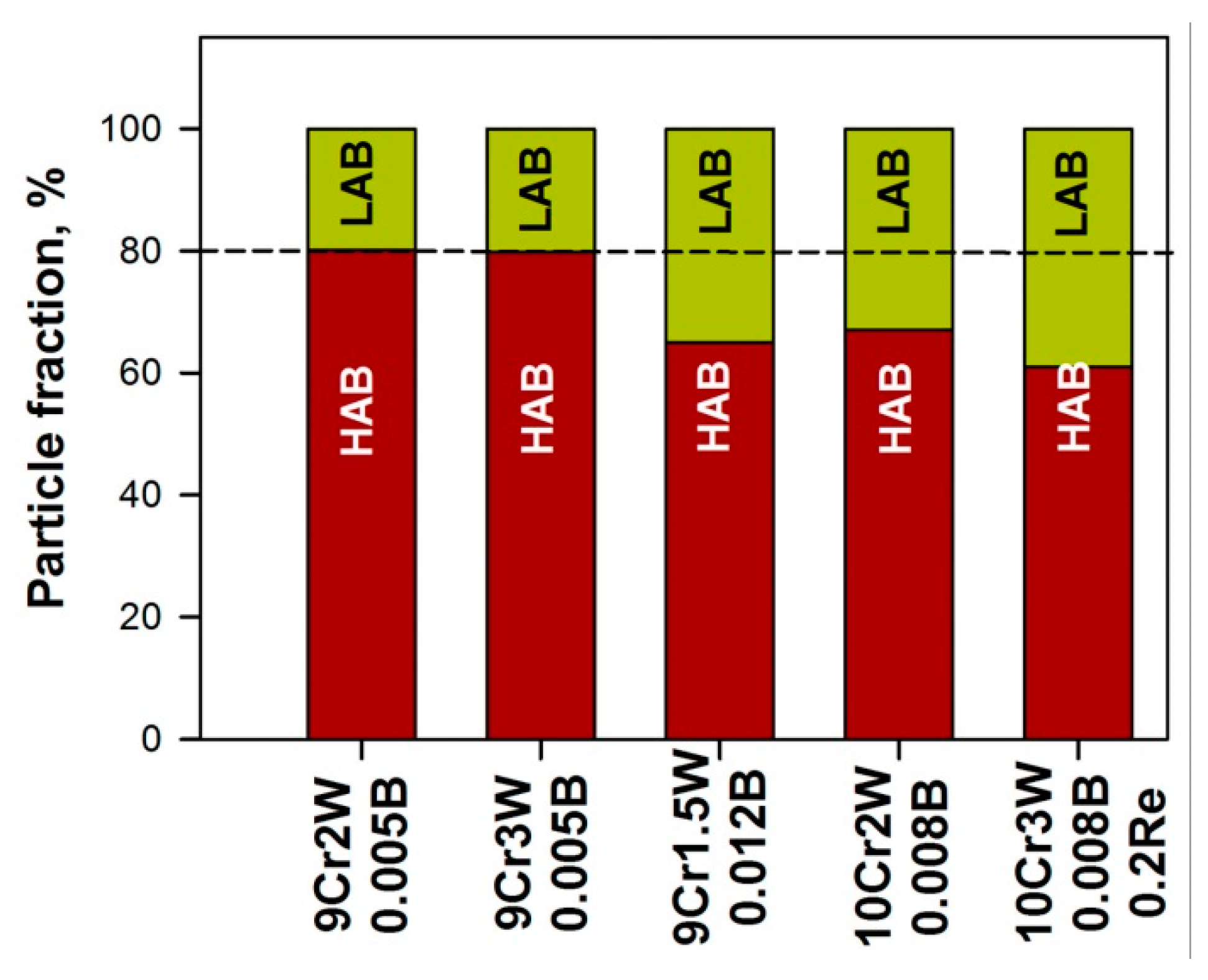
  • The increased (0.008–0.012%) B content in the 9–10%Cr-3%Co steels results in finer M23C6 carbides precipitated during tempering at 750–770 °C and higher their number particle density as compared with the steels with conventional 0.005% B. This dispersion of M23C6 carbides leads to an increase in the fraction of Laves phase nucleated along the low-angle boundaries from 20% to 35–40% in the B-enriched steels during creep.
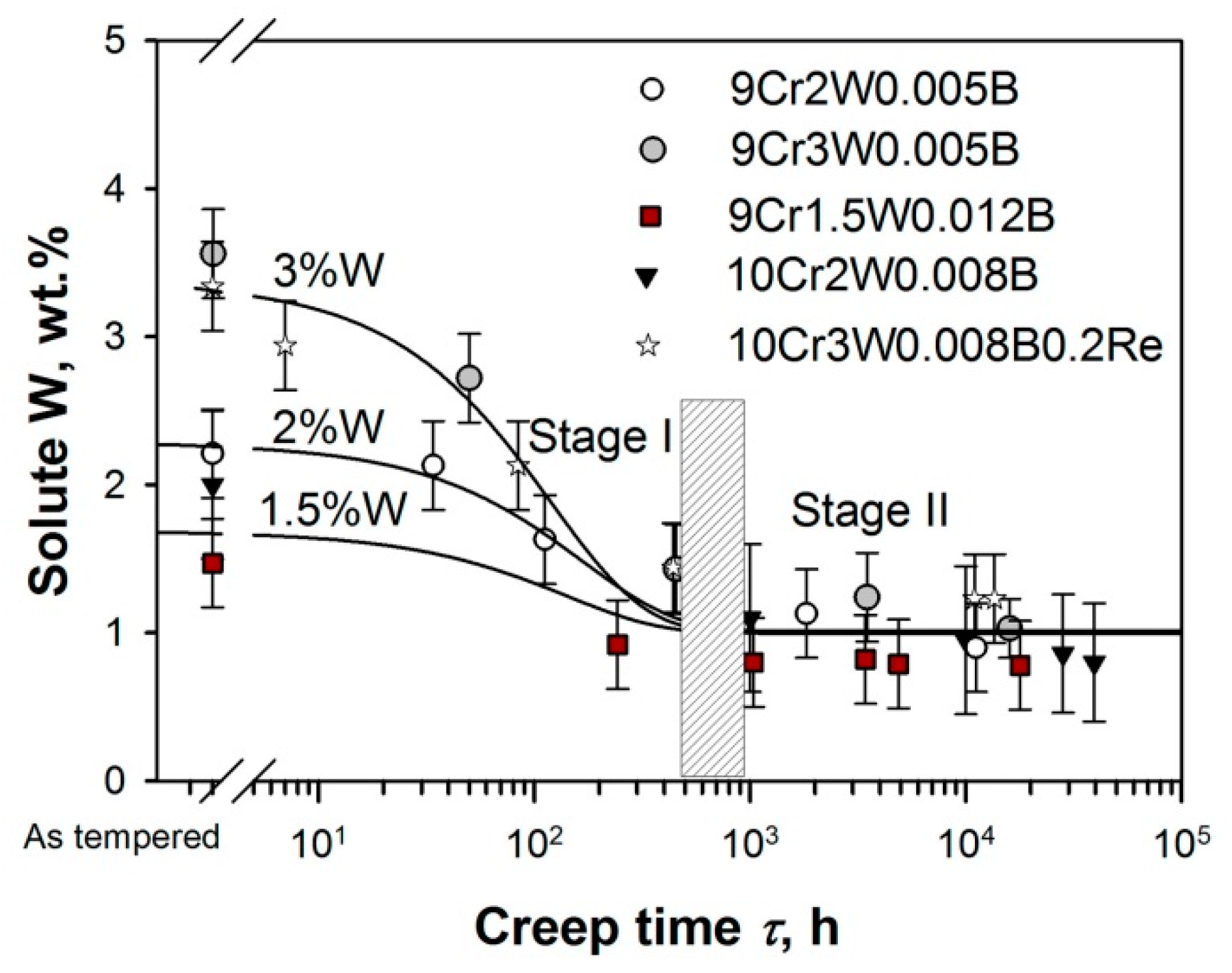
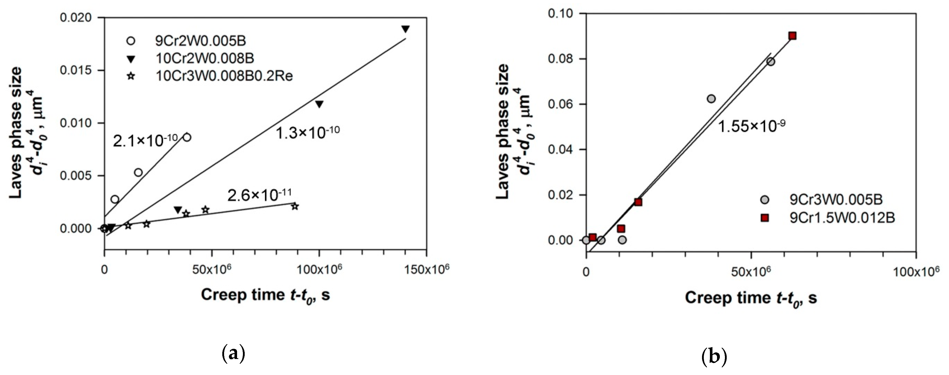
  • During creep in all steels studied with different W content (1.5–3%), the stage of depletion of excess W from the solid solution up to an equilibrium value is accompanied with the formation of nuclei of Laves phase along the low-angle and high-angle boundaries and their diffusion growth. At the stage of equilibrium W content in the solid solution, the coarsening of Laves phase occurs due to Ostwald ripening.
  • The highest and the lowest (W+Mo) content (Mo equivalent of 2.05% and 1.35%, respectively) provides the highest coarsening rate constant of 1.55 × 10⁻⁹ μm4 s−1 due to the great difference in Gibbs energy between fine particles at the LABs and large particles at the HABs.
  • The addition of Re (0.2%) to the 10%Cr steel provides the slowest coarsening of Laves phase among the steels studied due to the slow diffusion of W atoms and hindering their redistribution along boundaries.
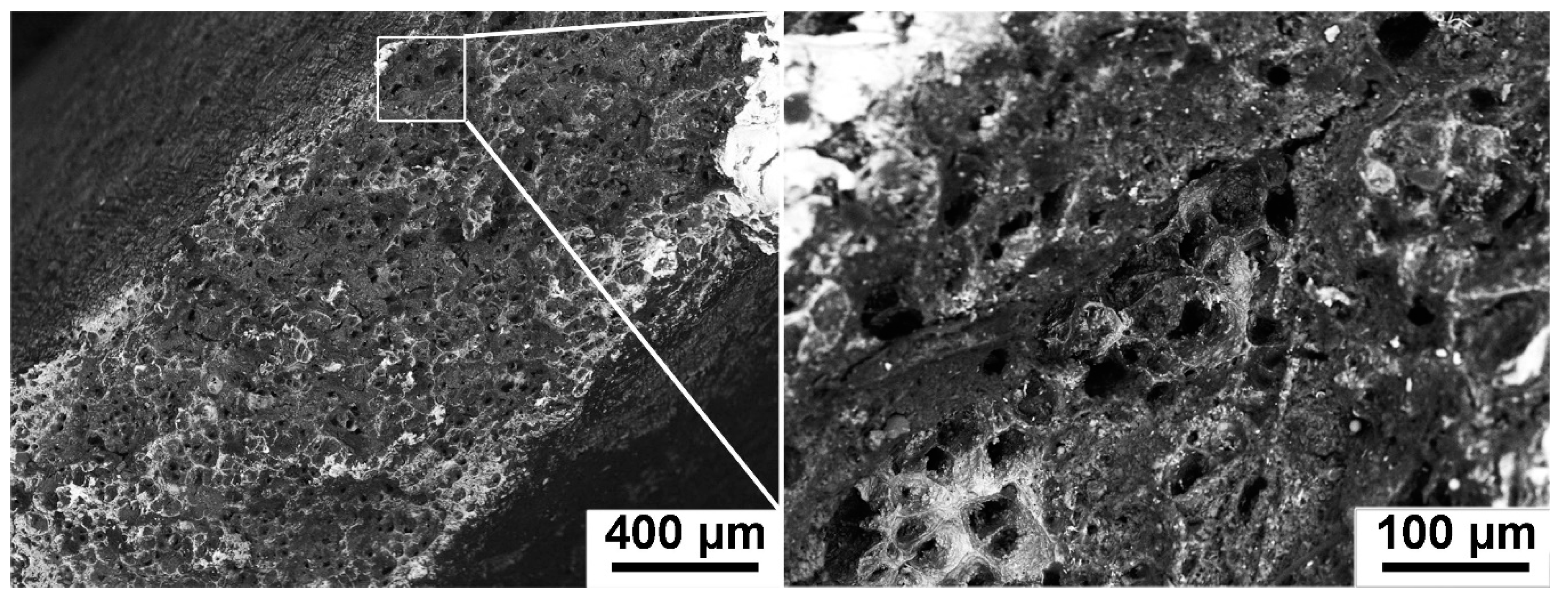
  • The fast coarsening of Laves phase at transition from the steady-state to tertiary creep stage can be a reason of the creep strength breakdown appearance in the 9Cr1.5W0.012B and 9Cr3W0.005B steels.

Author Contributions

A.F., N.D. and R.K. formulated the original problem, designed the study, developed the methodology and wrote the manuscript. A.F., I.N., E.T. and R.M. performed the experiment, collected data, and assisted with data analysis. A.F. and R.K. provided direction, guidance and interpretation of data. All authors have read and agreed to the published version of the manuscript.

Funding

This study was financially supported by the Russian Science Foundation No. 19-73-10089.

Data Availability Statement

The data presented in this study are available on request from the corresponding author. The data are not publicly available due to the data also forms part of an ongoing study.

Acknowledgments

The authors are grateful to the staff of the Joint Research Center, “Technology and Materials,” Belgorod State University, for their assistance with instrumental analysis.

Conflicts of Interest

The authors declare no conflict of interest.

References

  1. Bhadeshia, H.K.D.H. Design of ferritic creep-resistant steels. ISIJ Int. 2001, 41, 626–640. [Google Scholar] [CrossRef] [Green Version]
  2. Abe, F.; Kern, T.-U.; Viswanathan, R. Creep-Resistant Steels; Woodhead Publishing: Cambridge, MA, USA, 2008; p. 678. [Google Scholar]
  3. Abe, F. Precipitate design for creep strengthening of 9%Cr tempered martensitic steel for ultra-supercritical power plants. Sci. Technol. Adv. Mater. 2008, 9, 013002. [Google Scholar] [CrossRef] [PubMed] [Green Version]
  4. Maruyama, K.; Sawada, K.; Koike, J. Strengthening mechanisms of creep resistant tempered martensitic steel. ISIJ Int. 2001, 41, 641–653. [Google Scholar] [CrossRef]
  5. Nikitin, I.; Fedoseeva, A.; Kaibyshev, R. Strengthening Mechanisms of Creep-Resistant 12%Cr-3%Co Steel with low N and high B contents. J. Mater. Sci. 2020, 55, 7530–7545. [Google Scholar] [CrossRef]
  6. Dudova, N.; Mishnev, R.; Kaibyshev, R. Creep behavior of a 10%Cr heat-resistant martensitic steel with low nitrogen and high boron contents at 650 °C. Mater. Sci. Eng. A 2019, 766, 138353. [Google Scholar] [CrossRef]
  7. Wang, Y.; Mayer, K.-H.; Scholz, A.; Berger, C.; Chilukuru, H.; Durst, K.; Blum, W. Development of new 11%Cr heat resistant ferritic steels with enhanced creep resistance for steam power plants with operating steam temperature up to 650 °C. Mater. Sci. Eng. A 2009, 510–511, 180–184. [Google Scholar] [CrossRef]
  8. Klueh, R.L. Elevated temperature ferritic and martensitic steels and their application to future nuclear reactors. Int. Mater. Rev. 2005, 50, 287–310. [Google Scholar] [CrossRef] [Green Version]
  9. Hald, J. High-alloyed martensitic steel grades for boilers in ultra-supercritical power plants. In Materials for Ultra-Supercritical and Advanced Ultra-Supercritical Power Plants; Di Gianfrancesco, A., Ed.; Woodhead Publishing: Cambridge, MA, USA, 2017; pp. 77–97. [Google Scholar] [CrossRef]
  10. Armaki, H.G.; Chen, R.; Kano, S.; Maruyama, K.; Hasegawa, Y.; Igarashi, M. Strain-induced coarsening of nanoscale precipitates in strength enhanced high Cr ferritic steels. Mater. Sci. Eng. A 2012, 532, 373–380. [Google Scholar] [CrossRef]
  11. Suzuki, K.; Kumai, S.; Kushima, H.; Kimura, K.; Abe, F. Heterogeneous recovery and precipitation of Z-phase during long term creep deformation of modified 9Cr-1Mo steel. Tetsu-to-Hagane 2000, 86, 550–557. [Google Scholar] [CrossRef] [Green Version]
  12. Suzuki, K.; Kumai, S.; Kushima, H.; Kimura, K.; Abe, F. Precipitation of Z-phase and precipitation sequence during creep deformation of mod.9Cr-1Mo steel. Tetsu-to-Hagane 2003, 89, 691–698. [Google Scholar] [CrossRef] [Green Version]
  13. Sklenicka, V.; Kucharova, K.; Svoboda, M.; Kloc, L.; Bursik, J.; Kroupa, A. Long-term creep behavior of 9–12%Cr power plant steels. Mater. Char. 2003, 51, 35–48. [Google Scholar] [CrossRef]
  14. Danielsen, H.K. Review of Z phase precipitation in 9–12 wt-%Cr steels. Mater. Sci. Technol. 2016, 32, 126–137. [Google Scholar] [CrossRef] [Green Version]
  15. Fedoseeva, A.; Nikitin, I.; Dudova, N.; Kaibyshev, R. Strain-induced Z-phase formation in a 9% Cr-3% Co martensitic steel during creep at elevated temperature. Mater. Sci. Eng. A 2018, 724, 29–36. [Google Scholar] [CrossRef]
  16. Kaibyshev, R.; Mishnev, R.; Fedoseeva, A.; Dudova, N. The role of microstructure in creep strength of 9–12%Cr steels. Mater. Sci. Forum 2016, 879, 36–41. [Google Scholar] [CrossRef]
  17. Mishnev, R.; Dudova, N.; Kaibyshev, R. On the origin of the superior long-term creep resistance of a 10% Cr steel. Mater. Sci. Eng. A 2018, 713, 161–173. [Google Scholar] [CrossRef]
  18. Kaibyshev, R.; Mishnev, R.; Tkachev, E.; Dudova, N. Effect of Ni and Mn on the creep behaviour of 9–10 %Cr Steels with low N and high B. Trans. Indian Inst. Met. 2016, 69, 203–210. [Google Scholar] [CrossRef]
  19. Tkachev, E.; Belyakov, A.; Kaibyshev, R. Creep strength breakdown and microstructure in a 9%Cr steel with high B and low N contents. Mater. Sci. Eng. A 2020, 772, 138821. [Google Scholar] [CrossRef]
  20. Tkachev, E.; Belyakov, A.; Kaibyshev, R. Creep behavior and microstructural evolution of a 9%Cr steel with high B and low N contents. Mater. Sci. Eng. A 2018, 725, 228–241. [Google Scholar] [CrossRef] [Green Version]
  21. Abe, F. Effect of fine precipitation and subsequent coarsening of Fe2W Laves phase on the creep deformation behavior of tempered martensitic 9Cr-W steels. Metall. Trans. A 2005, 36A, 321–332. [Google Scholar] [CrossRef]
  22. Abe, F.; Ohba, T.; Miyazaki, H.; Toda, Y.; Tabuchi, M. Effect of W-Mo balance on long-term creep life of 9Cr steel. Mater. High. Temp. 2019, 36, 314–324. [Google Scholar] [CrossRef]
  23. Prat, O.; Garcia, J.; Rojas, D.; Sauthoff, G.; Inden, G. The role of Laves phase on microstructure evolution and creep strength of novel 9%Cr heat resistant steels. Intermetallics 2013, 32, 362–372. [Google Scholar] [CrossRef]
  24. Cui, H.; Sun, F.; Chen, K.; Zhang, L.; Wan, R.; Shan, A.; Wu, J. Precipitation behavior of Laves phase in 10%Cr steel X12CrMoWVNbN10-1-1 during short-term creep exposure. Mater. Sci. Eng. A 2010, 527, 7505–7509. [Google Scholar] [CrossRef]
  25. Maddi, L.; Deshmukh, G.S.; Ballal, A.R.; Peshwe, D.R.; Paretkar, R.K.; Laha, K.; Mathew, M.D. Effect of Laves phase on the creep rupture properties of P92 steel. Mater. Sci. Eng. A 2016, 668, 215–223. [Google Scholar] [CrossRef]
  26. Zhen, L.; Zhengdong, L.; Xitao, W.; Zhengzong, C. Investigation of the microstructure and strength in G115 steel with the different concentration of tungsten during creep test. Mater. Charact. 2019, 49, 95–104. [Google Scholar] [CrossRef]
  27. Fedoseeva, A.; Nikitin, I.; Dudova, N.; Kaibyshev, R. On effect of rhenium on mechanical properties of a high-Cr creep resistant steel. Mater. Lett. 2019, 269, 81–84. [Google Scholar] [CrossRef]
  28. Fedoseeva, A.; Nikitin, I.; Dudova, N.; Kaibyshev, R. Superior creep resistance of a high-Cr steel with Re additives. Mater. Lett. 2020, 262, 127183. [Google Scholar] [CrossRef]
  29. Fedoseeva, A.; Dudova, N.; Kaibyshev, R. Effect of stresses on the structural changes in high-chromium steel upon creep. Phys. Met. Metallogr. 2017, 118, 591–600. [Google Scholar] [CrossRef]
  30. Fedoseeva, A.; Nikitin, I.; Dudova, N.; Kaibyshev, R. Nucleation of W-rich carbides and Laves phase in a Re-containing 10% Cr steel during creep at 650 °C. Mater. Charact. 2020, 169, 110651. [Google Scholar] [CrossRef]
  31. Fedoseeva, A.; Dudova, N.; Glatzel, U.; Kaibyshev, R. Effect of W on tempering behaviour of a 3%Co modified P92 steel. J. Mater. Sci. 2016, 51, 9424–9439. [Google Scholar] [CrossRef]
  32. Fedoseeva, A.; Dudova, N.; Kaibyshev, R. Creep strength breakdown and microstructure evolution in a 3%Co modified P92 steel. Mater. Sci. Eng. A 2016, 654, 1–12. [Google Scholar] [CrossRef]
  33. Sawada, K.; Takeda, M.; Maruyama, K.; Ishii, R.; Yamada, M.; Nagae, Y.; Komine, R. Effect of W on recovery of lath structure during creep of high chromium martensitic steels. Mater. Sci. Eng. A 1999, 267, 19–25. [Google Scholar] [CrossRef]
  34. Miyata, K.; Sawaragi, Y. Effect of Mo and W on the phase stability of precipitates in low Cr heat resistant steels. ISIJ Int. 2001, 41, 281–289. [Google Scholar] [CrossRef] [Green Version]
  35. Abe, F.; Nakazawa, S. The effect of tungsten on creep behavior of tempered martensitic 9Cr steels. Metall. Trans. A 1992, 23A, 3025–3034. [Google Scholar] [CrossRef]
  36. Tsuchida, Y.; Okamoto, K. Improvement of creep rupture strength of high Cr ferritic steel by addition of W. ISIJ Int. 1995, 35, 317–323. [Google Scholar] [CrossRef]
  37. Sanhueza, J.P.; Rojas, D.; Prat, O.; Garcia, J.; Melendrez, M.F.; Saurez, S. Investigation of Ta-MX/Z-phase and Laves phase as precipitation hardening particles in a 12 pct Cr heat-resistant steel. Metall. Mater. Trans. A 2018, 49, 2951–2962. [Google Scholar] [CrossRef]
  38. Abe, F. Coarsening behavior of lath and its effect on creep rates in tempered martensitic 9Cr-W steels. Mater. Sci. Eng. A 2004, 387-389, 565–569. [Google Scholar] [CrossRef]
  39. Dimmler, G.; Weinert, P.; Kozeschnik, E.; Cerjak, H. Quantification of the Laves phase in advanced 9–12%Cr steels using a standard SEM. Mater. Charact. 2003, 51, 341–352. [Google Scholar] [CrossRef]
  40. Korcakova, L.; Hald, J.; Somers Marcel, A.J. Quantification of Laves phase particle size in 9CrW steel. Mater. Charact. 2001, 47, 111–117. [Google Scholar] [CrossRef]
  41. Hattestrand, M.; Andren, H.-O. Influence of strain on precipitation reactions during creep of an advanced 9% chromium steel. Acta Mater. 2001, 49, 2123–2128. [Google Scholar] [CrossRef]
  42. Isik, M.I.; Kostka, A.; Eggeler, G. The nucleation of Laves phase particles during high-temperature exposure and creep of tempered martensite ferritic steels. Acta Mater. 2014, 81, 230–240. [Google Scholar] [CrossRef]
  43. Isik, M.I.; Kostka, A.; Yardley, V.A.; Pradeep, K.G.; Duarte, M.J.; Choi, P.P.; Raabe, D.; Eggeler, G. The nucleation of Mo-rich Laves phase particles adjacent to M23C6 micrograin boundary carbides in 12% Cr tempered martensite ferritic steels. Acta Mater. 2015, 90, 94–104. [Google Scholar] [CrossRef]
  44. Fedoseeva, A.; Dudova, N.; Kaibyshev, R. Role of tungsten in the tempered martensite embrittlement of a modified 9%Cr steel. Metall. Mater. Trans. A 2017, 48, 982–998. [Google Scholar] [CrossRef]
  45. Kimura, K.; Kushima, H.; Abe, F.; Yagi, K. Inherent creep strength and long term creep strength properties of ferritic steels. Mater. Sci. Eng. A 1997, 234–236, 1079–1082. [Google Scholar] [CrossRef]
  46. Jones, D.R.H.; Ashby, M.F. Chapter 23—Mechanisms of Creep, and Creep-Resistant Materials. In Engineering Materials 1 An Introduction to Properties, Applications and Design, 5th ed.; Jones, D.R.H., Ashby, M.F., Eds.; Elsevier: Cambridge, MA, USA, 2019; pp. 381–394. [Google Scholar] [CrossRef]
  47. Ardell, A.J. On the coarsening of grain boundary precipitates. Acta Metall. 1972, 20, 601–609. [Google Scholar] [CrossRef]
  48. Kirchner, H.O.K. Coarsening of grain-boundary precipitates. Metall. Trans. 1972, 2, 2861–2864. [Google Scholar] [CrossRef]
  49. Yao, J.H.; Elder, K.R.; Guo, H.; Grant, M. Theory and simulation of Ostwald ripening. Phys. Rev. B. 1993, 47, 14110–14125. [Google Scholar] [CrossRef] [Green Version]
  50. Wagner, C. Theorie der Alterung von Niederschlaegen durch Umlosen (Ostwald Reifung). Phys. Chem. Chem. Phys. 2010, 65, 581–591. [Google Scholar] [CrossRef]
  51. Lifshitz, M.; Slyozov, V.V. The kinetics of precipitation from supersaturated solid solutions. J. Phys. Chem. Solids 1961, 19, 35–50. [Google Scholar] [CrossRef]
Figure 1. (a) The typical tempered martensite lath structure in the 9Cr2W0.005B steel; (b) the features of the lath structure related to increasing the B, (W+Mo) and Cr contents such as the formation of dense chains of M23C6 carbides along the high-angle boundaries and low-angle boundaries in the 9–10%Cr steels with high B content and the formation of W-rich particles (M6C and/or Laves) in the 9–10%Cr steels with 2–3%W.
Metals 11 00060 g001
Figure 2. (a) Applied stress vs. time to rupture curves; (b) minimum creep rate vs. applied stress curves for the steels studied at 650 °C under the applied stresses ranging from 80 to 200 MPa with a step of 20 MPa. Numbers in (b) indicate the “apparent” stress exponent.
Metals 11 00060 g002
Figure 3. Creep rate vs. strain and creep rate vs. time curves of the steels studied at 650 °C under the applied stresses of 180, 140, and 120 MPa.
Metals 11 00060 g003
Figure 4. SEM-back scattered electron (BSE) images of all steels studied after some creep rupture tests corresponding to the regions of short-term creep (180 MPa), transition creep (140 MPa) and long-term creep (120 MPa). Numbers indicate the rupture time for each creep test. The white and grey particles correspond to Laves phase and M23C6 carbides, respectively.
Metals 11 00060 g004
Figure 5. TEM images of all steels studied after some creep rupture tests corresponding to the regions of short-term creep (180 MPa), transition creep (140 MPa), and long-term creep (120 MPa). Numbers indicate the rupture time for each creep test. The black and grey particles correspond to Laves phase and M23C6 carbides, respectively.
Metals 11 00060 g005
Figure 6. The depletion of W from the solid solution for the steels studied.
Metals 11 00060 g006
Figure 7. (a) Size distribution of Laves phase particles for the steels studied after some creep rupture tests corresponding to the region of the short-term creep (180 MPa), the transition region (140 MPa), and the region of long-term creep (120 MPa), numbers indicate the rupture time; (b) change in the mean size of Laves phase particles with creep time in the steels that is subdivided into two stages of growth.
Metals 11 00060 g007
Figure 8. The ratio between the number density of Laves phase particles located at the HABs and LABs after creep times ranging from 454 to 1037 h in the gauge section of crept samples.
Metals 11 00060 g008
Figure 9. The time dependence of the size of Laves phase for: (a) the 9Cr2W0.005B, 10Cr2W0.008B, and 10Cr3W0.008B0.2Re steels; (b) the 9Cr3W0.005B and 9Cr1.5W0.012B steels. Numbers indicate the coarsening rate constant (in μm4 s−1).
Metals 11 00060 g009
Figure 10. Scheme describing the difference in the nucleation of Laves phase in the 9–10%Cr steels with standard B content (0.005% B) and high B content (0.008–0.012% B) and different W content (1.5–3%).
Metals 11 00060 g010
Figure 11. Fracture surface of the specimens of the 9Cr1.5W0.012 B steel tested at the applied stress of 120 MPa.
Metals 11 00060 g011
Table 1. Chemical compositions of the 9–10%Cr-3%Co steels studied (wt. %).
SteelFeCCrCoMoWVNbBNSiMnNiRe
9Cr2W0.005Bbal.0.129.33.10.42.00.20.060.0050.050.080.20.2
9Cr3W0.005Bbal.0.129.53.20.53.10.20.060.0050.050.060.20.04
9Cr1.5W0.012Bbal.0.109.02.80.61.50.20.050.0120.0070.120.40.04
10Cr2W0.008Bbal.0.1010.03.00.72.00.20.050.0080.0030.060.10.24
10Cr3W0.008B0.2Rebal.0.119.93.20.12.90.20.070.0080.0020.030.10.170.2
Table 2. Structural parameters of the 9–10%Cr martensitic steels after heat treatment.
SteelsStructureParticles
PAG size, μmLath Size,
μm
ρdisl, ×1014 m−2Size, nmVolume Fraction (by Thermo-Calc), %Density of Particles Located at the Boundaries, μm−1
M23C6/MX/
M6C/Laves
M23C6/MXHABLAB
9Cr2W0.005B10 ± 20.4 ± 0.052.0 ± 0.0190/30/-/-2.27/0.341.410.94
9Cr3W0.005B20 ± 20.4 ± 0.052.0 ± 0.0190/30/350/802.31/0.341.410.94
9Cr1.5W0.0012B26 ± 20.3 ± 0.052.6 ± 0.0170/49/-/-1.79/0.044.312.18
10Cr2W0.008B35 ± 20.4 ± 0.051.7 ± 0.0170/30/25/-2.05/0.064.312.18
10Cr3W0.008B0.2Re51 ± 20.3 ± 0.052.0 ± 0.0170/30/28/-1.97/0.086.752.35
Table 3. Effect of applied stresses on rupture time (numerator) and off-set time (denominator), at which minimum creep rate is achieved, and an information on durations of interrupted creep tests at 650 °C (in hours).
Steel200 MPa (Ruptured)180 MPa (Ruptured)160 MPa (Ruptured)140 MPa (Ruptured)120 MPa (Ruptured)120 MPa
(Interrupted)
100 MPa
(Ruptured)
9Cr2W0.005B34/3112/47487/1621828/7104985/174411,151/6144
9Cr3W0.005B207/80454/2531703/4383489/163010,952/266415,998/3144
9Cr1.5W0.012B243/1311035/3003430/14344883/200017,862/-
10Cr2W0.008B18/7210/1101425/64339,437/17,7731000-
10Cr3W0.008B0.2Re8/383/35440/12010,987/148313,495/1380100025,065/1499
Table 4. Structural parameters after creep tests up to rupture in the gauge sections.
SteelStructureParticles
Lath/Subgrain Sizes μmρdisl, ×1014 m−2Size, nmVolume Fraction *, %Density of Laves Phase Located at the Boundaries, μm−1
M23C6/LavesM23C6/LavesHABLAB
Applied stress of 180 MPa
9Cr2W0.005B0.60 ± 0.050.5 ± 0.01120/1362.34/1.201.920.43
9Cr3W0.005B0.57 ± 0.051.1 ± 0.01100/1082.37/2.493.160.80
9Cr1.5W0.012B0.56 ± 0.051.0 ± 0.0176/1641.87/0.901.480.85
10Cr2W0.008B0.70 ± 0.051.2 ± 0.0170/562.10/1.610.260.1
10Cr3W0.008B0.2Re0.50 ± 0.050.7 ± 0.0164/1102.00/1.891.970.85
Applied stress of 140 MPa
9Cr2W0.005B1.45 ± 0.050.2 ± 0.01185/2452.34/1.201.970.55
9Cr3W0.005B0.65 ± 0.051.0 ± 0.01113/1302.37/2.491.860.84
9Cr1.5W0.012B0.78 ± 0.050.5 ± 0.01107/2831.87/0.900.950.57
10Cr2W0.008B0.66 ± 0.051.1 ± 0.01100/1752.10/1.611.230.65
10Cr3W0.008B0.2Re1.22 ± 0.050.2 ± 0.01120/2002.00/1.891.830.36
Applied stress of 120 MPa
9Cr2W0.005B1.50 ± 0.050.1 ± 0.01200/2802.34/1.201.250.52
9Cr3W0.005B0.78 ± 0.050.5 ± 0.01220/5002.37/2.490.470.51
9Cr1.5W0.012B0.91 ± 0.050.4 ± 0.01114/3671.87/0.900.730.51
10Cr2W0.008B0.86 ± 0.050.2 ± 0.01120/3182.10/1.610.580.42
10Cr3W0.008B0.2Re0.92 ± 0.050.2 ± 0.01106/2122.00/1.891.420.42
* Calculated by the Thermo-Calc software.
Table 5. The number particle density and mean size of Laves phase particles located at the high-angle boundaries (numerator) and low-angle boundaries (denominator) in steels after 454–1037 h of creep at 650 °C.
Steel9Cr2W0.005B9Cr3W0.005B9Cr1.5W0.012B10Cr2W0.008B10Cr3W0.008B0.2Re
Creep conditions160 MPa
487 h
180 MPa
454 h
160 MPa
1037 h
120 MPa
1000 h (interrupted)
120 MPa
1001 h (interrupted)
Number particle density, μm−12.50/0.623.16/0.801.56/0.851.56/0.771.49/0.95
Mean size, nm176/135106/165200/159160/126150/100
Publisher’s Note: MDPI stays neutral with regard to jurisdictional claims in published maps and institutional affiliations.

