Article

Improving the Fatigue of Newly Designed Mechanical System Subjected to Repeated Impact Loading

by
Seongwoo Woo
1,*,
Dennis L. O’Neal
2,
Dereje Engida Woldemichael
1,
Samson Mekbib Atnaw
1 and
Muluneh Mekonnen Tulu
1
1
Department of Mechanical Engineering, College of Electrical and Mechanical Engineering, Addis Ababa Science & Technology University, PO Box 16417 Addis Ababa, Ethiopia
2
Department of Mechanical Engineering, Dean of Engineering and Computer Science, Baylor University, Waco, TX 76798-7356, USA
*
Author to whom correspondence should be addressed.
Metals 2021, 11(1), 139; https://doi.org/10.3390/met11010139
Submission received: 16 December 2020 / Revised: 31 December 2020 / Accepted: 4 January 2021 / Published: 12 January 2021
(This article belongs to the Special Issue Computational Methods for Fatigue and Fracture)

Abstract

:
This paper develops parametric accelerated life testing (ALT) as a systematic reliability method to produce the reliability quantitative (RQ) specifications—mission cycle—for recognizing missing design defects in mechanical products as applying the accelerated load, expressed as the inverse of stress ratio, R. Parametric ALT is a way to enhance the prediction of fatigue failure for mechanical systems subjected to repeated impact loading. It incorporates: (1) A parametric ALT plan formed on the system BX lifetime, (2) a fatigue failure and design, (3) customized ALTs with design alternatives, and (4) an assessment of whether the last design(s) of the system fulfills the objective BX lifetime. A BX life concept with a generalized life-stress model and a sample size equation are suggested. A domestic refrigerator hinge kit system (HKS), which was a newly designed mechanical product, was used to illustrate the methodology. The HKS was subjected to repeated impact loading resulting in failure of the HKS in the field. To conduct ALTs, a force and momentum balance was utilized on the HKS. A straightforward impact loading of the HKS in closing the refrigerator door was examined. At the first ALT, the housing of the HKS failed. As an action plan, the hinge kit housing was modified by attaching inside supporting ribs to the HKS to provide sufficient mechanical strength against its loading. At the second ALT, the torsional shaft in the HKS made with austenitic ductile iron (18 wt% Ni) failed. The cracked torsional shaft for the 2nd ALTs came from its insufficient rounding, which failed due to repeated stress. As an action plan, to have sufficient material strength for the repetitive impact loads, the torsional shaft was reshaped to give it more rounding from R0.5 mm to R2.0 mm. After these modifications, there were no problems at the third ALT. The lifetime of the HKS in the domestic refrigerator was assured to be B1 life 10 years.

1. Introduction

Because of the competitiveness in the global market, manufacturers must continually innovate and improve their products. Often, this involves new technologies and design features for the product that must be quickly delivered to the marketplace. However, without sufficient testing or anticipation of how the features may be used or misused, the introduction of these new features may increase failures of the product in the field and negatively impact the company’s image. These added attributes are often requested or desired by consumers, and companies strive to include these features in new design specifications for the product. The features for the newly designed mechanical product may not be evaluated entirely before being introduced into the market. Thus, any defects may only show themselves as performance issues once the product is in the marketplace. Reliability quantitative (RQ) specifications using proper methodology should be included and evaluated in the product design that meets its expected life before it will be released [1,2,3,4].
Mechanical systems such as automobiles, airplanes, and refrigerators [5] convert forms of energy to achieve a specific function (movement of the automobile or airplane and cooling for the refrigerator). The energy conversion requires forces and movement of components, which eventually produce the desired functions with multiple system mechanisms. In the process, mechanical systems are typically subjected to repeated loads. Most mechanical products are made of multi-module structures. If the modules are properly designed and assembled, mechanical systems can work properly and perform their planned functions. For example, in utilizing the vapor-compression refrigeration cycle, a domestic refrigerator is used to cool or freeze food. The refrigerator evaporator provides cooled air to both the refrigerator and freezer sections. A refrigerator has multiple subsystems—Door, cabinet, drawers and shelves, control system, compressor, motor, water supplying device, heat exchangers, and other various components. The total number of parts might be as high as 2000. The product lifetime is targeted to have no less than a B20 life 10 years. As a refrigerator consists of 8 to 10 modules (see Figure 1a) and each module may contain as many as 100 components, the lifetime target of each module needs to have a B1 life of 10 years. The product lifetime of the system is determined by the module with the shortest life, which is module #3 in Figure 1b.
To avoid the failure of a mechanical system in the field [6,7], it should be designed to robustly endure or survive whatever usage conditions the customers subject the system. Design faults should be recognized and altered by statistical methodology [8] or reliability testing [9] before a commercially manufactured goods is released. However, the statistical methodology and subsequent testing may require large numbers of computations for an optimum solution but may not identify the ultimate failures that may occur in the field by consumers. If there are design faults that cause an inadequacy of strength (or stiffness) when a system is subjected to repeat loading, the system will fail before its expected lifetime due to fatigue failure. American Society for Testing and Materials (ASTM) procedures typically require large samples, skilled personnel, testing apparatus arranged by data acquisition systems, etc. Thus, discovering possible mechanical failures such as fatigue can involve time-consuming and costly testing procedures [10,11,12,13]. To recognize these limitations, there have been numerous attempts to systematically evolve fatigue testing [14]. It is difficult to estimate the lifetime cycles of problematic parts in multi-module products where failures rarely occur in the field due to design flaws.
An alternative method, based on reliability block diagrams [15], is where the accelerated life testing (ALT) could be scrutinized [16,17,18,19,20,21,22,23,24]. It includes test planning for the product, failure mechanics, accelerated procedures, sample size equation, etc. Elsayed [25] categorized physics/statistics, statistical, and physics/experimental-based models for assessment. Meeker [26] proposed numerous feasible recommendations to organize an ALT. Carrying out an ALT [27,28] requires numerous concepts such as the BX life for the product test plan based on reliability engineering, a life-stress model, sample size equation, and fracture mechanics [29,30,31,32] because failure may occur suddenly from the frail components in a system. Contemporary experimental methods may fail to reproduce the design defects. These methods may evaluate insufficient part samples in multi-module products and may not identify the failure(s) that actually happen in the marketplace.
To implement the optimal design of a mechanical system, engineers have relied on traditional design approaches such as strength of materials [33]. A recent fracture mechanics study proposed that the crucial elements might be fracture toughness as an alternative of strength as an applicable material property. As quantum mechanics has been used in electronic technology, designers have identified system failures from micro-void coalescence (MVC) and noted a great number of metallic alloys or numerous engineering plastics [34]. To determine the failure phenomena of a mechanical system, a better life-stress model might be combined with the traditional design approaches and applicable methodology of identifying the failure of electronic parts due to small cracks or pre-existing defects. This approach would not be feasible to model using current finite element methods (FEMs) [35].
To better identify product failures in the marketplace, there is another engineering perspective that incorporates the FEM [36]. Many engineers believe that rare system failures might be evaluated by: (1) Mathematical modeling utilizing Newtonian or Lagrangian techniques; (2) obtaining the system stress/strain from the time response for (dynamic) loads; (3) making use of the rain-flow counting method for von-Mises stress [37,38]; and (4) approximating system damage by Palmgren–Miner’s rule [39]. Nevertheless, utilizing a systematic method that can give closed-form, precise solutions would involve utilizing numerous assumptions that might not identify multi-module system failures, due to material defects such as micro-voids and contacts when subjected to loads.
This study introduces a parametric ALT as a systematic reliability method that can generate the RQ specifications such as mission time for identifying and modifying the design faults of newly designed mechanical systems. It incorporates: (1) An ALT plan formed on system BX lifetime, (2) a load examination for ALT, (3) customized ALTs with the alterations, and (4) an assessment of whether the last design(s) of the system fulfills the objective BX lifetime. A newly designed hinge kit system (HKS) in a domestic refrigerator subjected to repeated impact loading is provided as an example.

2. Parametric ALT for Mechanical System

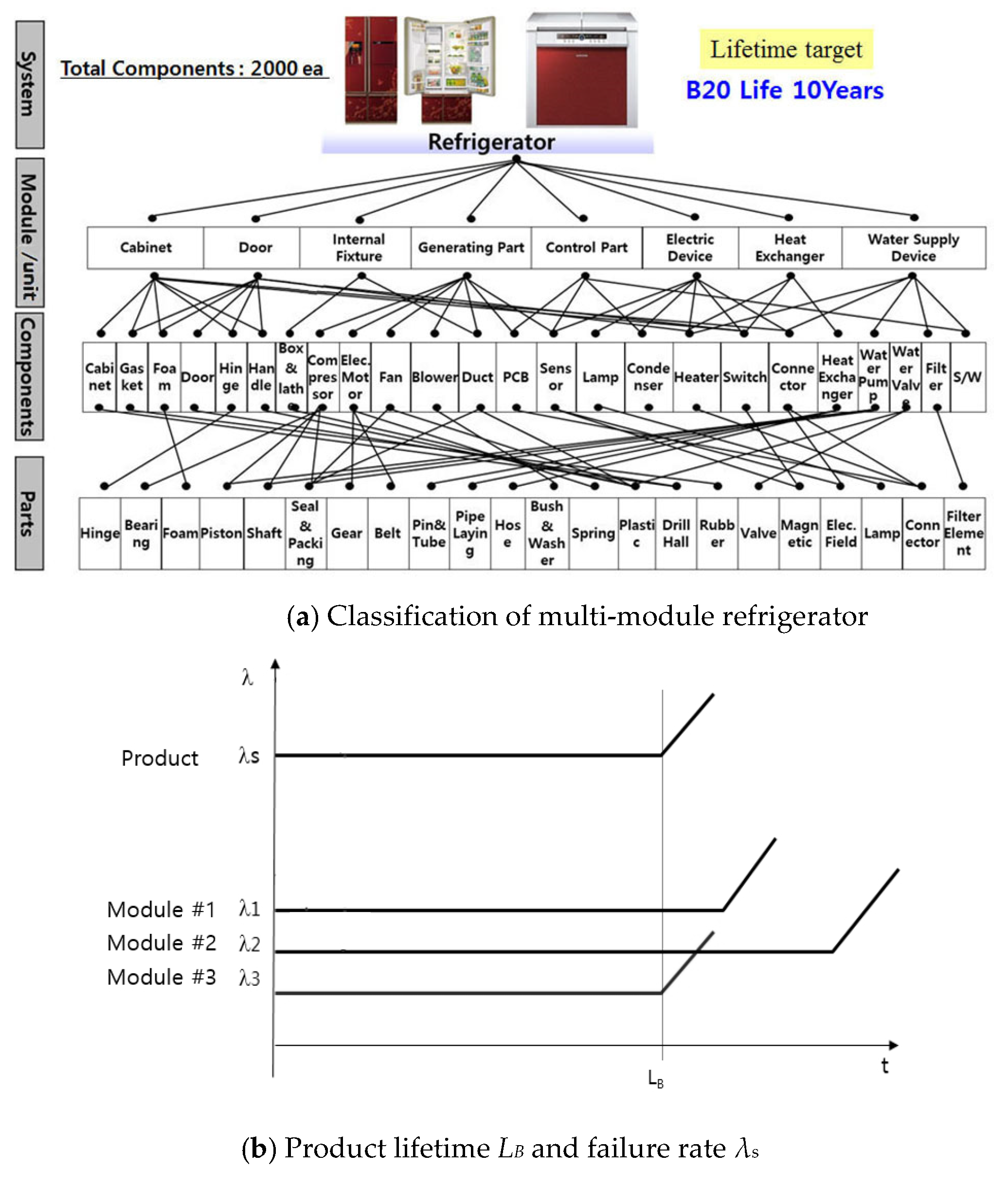
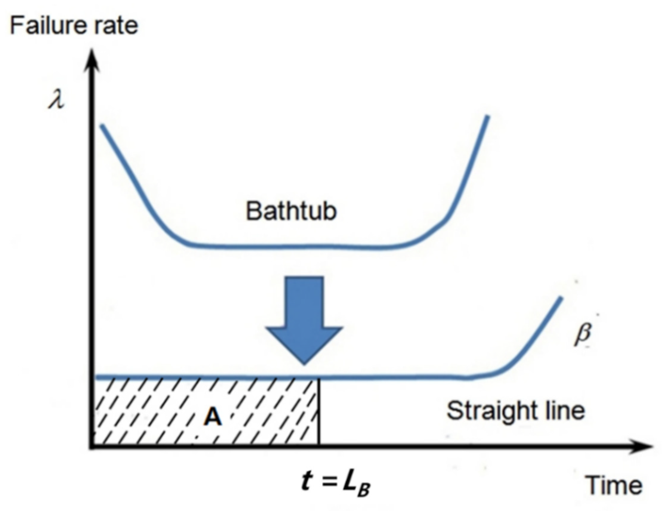
2.1. Definition of BX lifetime for Putting a Whole Parametric ALT Plan

To carry out a parametric ALT, the BX life as a measure of system lifetime is required. The BX life, LB, can be explained as the elapsed time at which X percent of a collection of a selected product might have failed. Otherwise, ‘BX life Y years’ is a good expression for product lifetime that helps to satisfactorily decide the cumulative failure rate of a product and respond to field circumstances. For instance, if the lifetime of a product has a B20 life of 10 years, then 20% of the population might have been unsuccessful in achieving one’s goal for 10 years of the working period.
Reliability might be explained as the system’s ability to work under specified conditions for a stated period of time [40]. Product reliability, as shown in Figure 2, is often illustrated with the “bathtub curve” that is composed of three sections [41]. First, there is a declining failure rate in the earlier product life (β < 1). Secondly, there is a constant failure rate (β = 1) in the middle of the product’s life. Lastly, there is a growing failure rate at the end of the product life (β > 1). If a manufacturer produces a product whose failure rate follows the bathtub curve, it might have difficulties achieving success in the marketplace because of shorted lifetime and large failure rates due to design faults in the early product life. Manufacturers need to enhance the product design by increasing its reliability targets to (1) eliminate untimely failures, (2) lessen random failures over the product lifetime, and (3) lengthen system lifetime. As the design of a mechanical product improves, its failure rate in the marketplace should decease and the product lifetime should be extended. For such circumstances, the conventional bathtub curve might be changed to a straight line in Figure 2.
The failure rate on the bathtub (or straight line) can be defined as
λ = f R = d F / d t R = ( 1 R ) R = R R
where λ is the failure rate, f is the failure density function, R is reliability, and F is unreliability.
If Equation (1) is integrated over time, we can obtain the X% cumulative failure F(LB) at BX life, LB. That is,
λ d t = ln R
That is to say, it can be expressed as:
A = λ L B = 0 L B λ ( t ) d t = ln R ( L B ) = ln ( 1 F ) F ( L B )
where LB is the BX life, A is the area that can be obtained from the multiplication of failure rate, λ, and BX life, LB.
Consequently, if a product failure follows an exponential distribution, the reliability of a mechanical product can be defined as:
R ( L B ) = 1 F ( L B ) = e λ L B 1 λ L B
Equation (4) is relevant for when there are less than approximately 20% of the cumulative failures for the system [42]. The mechanical system could be improved by obtaining the objective product lifetime, LB, and failure rate, λ, after optimally identifying the market failure by parametric ALT and modifying the problematic design (or material) of structures (Figure 3).
In seeking to improve the lifetime target of a mechanical system through an ALT examination, there are three potential product modules: (1) An altered module, (2) a newly designed module, and (3) an alike module to the previous design base on demand in the marketplace. The newly designed HKS in the refrigerator examined here as a case study was a new module that had design faults that had to be rectified because customers asked for replacements with a new one because the product failed during its expected lifetime.
The new module B from the market data shown in Table 1 had a failure rate of 0.24% per year and a B1 life of 4.2 years. To answer customer requests, a new lifetime target for the HKS was set to have B1 life 10 years with a cumulative failure rate of one percent.

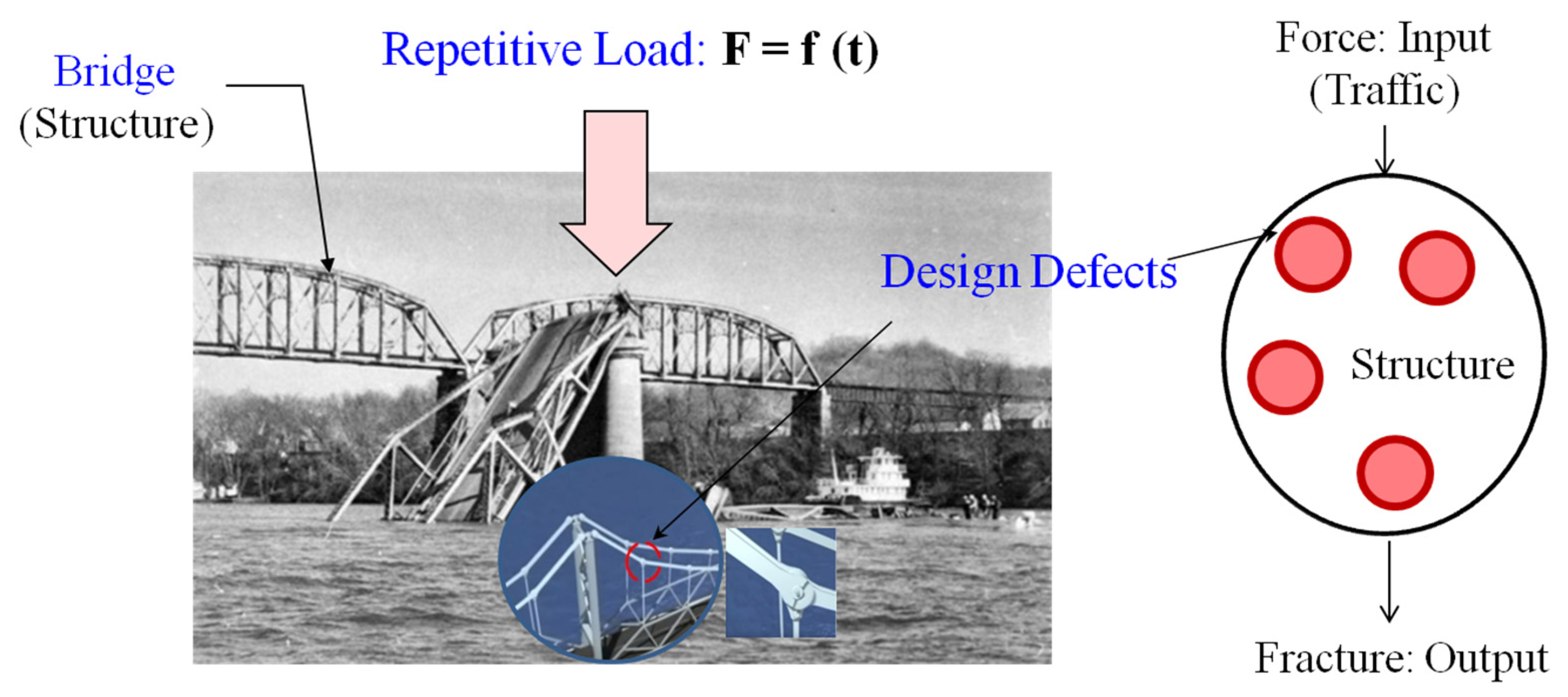
2.2. Failure Mechanics and Accelerated Testing for Design

Mechanical systems typically move energy and power from one location to another through mechanical mechanisms. If there is a design fault in the structure that causes an inadequate strength (or stiffness) when the loads are exerted, the mechanical system may suddenly fail before its anticipated lifetime. Fatigue due to design flaws can be characterized by two factors: (1) the stress due to loads on the structure and (2) the type of materials (or shape) used in the product. In reproducing the system failure by a parametric ALT, a designer could optimally design components with proper shapes and materials. The product could sustain repetitive loads over its lifetime so that it could achieve the targeted reliability (Figure 4).
The most important issue for a reliability test is how quickly the possible failure mode might be obtained. A failure model must be derived and its associated coefficients determined. The life-stress (LS) model also incorporates stresses and reaction parameters. The generalized life-stress (LS) model [1,43,44] might thus be defined as
T F = A [ sinh ( a S ) ] 1 exp ( E a k T )
The sine hyperbolic expression [ sinh ( aS ) ] 1 in Equation (5) can be expressed as:
  • ( S ) 1 in Equation (5) has a little linear effect at first,
  • ( S ) n in Equation (5) has what is regarded as a medium effect, and
  • ( e aS ) 1 in Equation (5) is big in the end.
An ALT is normally performed in the medium range, and Equation (5) might be defined as
T F = A ( S ) n exp ( E a k T )
As the stress of a mechanical system may not be easy to measure during testing, Equation (6) must be redefined. When the power is defined as the multiplication of flows and effort, stresses may come from effort in a multi-port system (Table 2) [45].
Stress is a physical quantity that indicates the internal forces that adjacent particles of a continual material apply on each other. For a mechanical system, because stress comes from effort, Equation (6) might be redefined as
T F = A ( S ) n exp ( E a k T ) = B ( e ) λ exp ( E a k T )
where A and B are constants
To derive the acceleration factor (AF) that can mainly enfluence the assessment of fatigue strength in product, expressed as the inverse of the stress ratio, R (=σminmax), from Equation (7), AF might be expressed as the proportion between the adequate elevated stress amounts and normal working conditions. AF might be altered to incorporate the effort ideas:
A F = ( S 1 S 0 ) n [ E a k ( 1 T 0 1 T 1 ) ] = ( e 1 e 0 ) λ [ E a k ( 1 T 0 1 T 1 ) ]

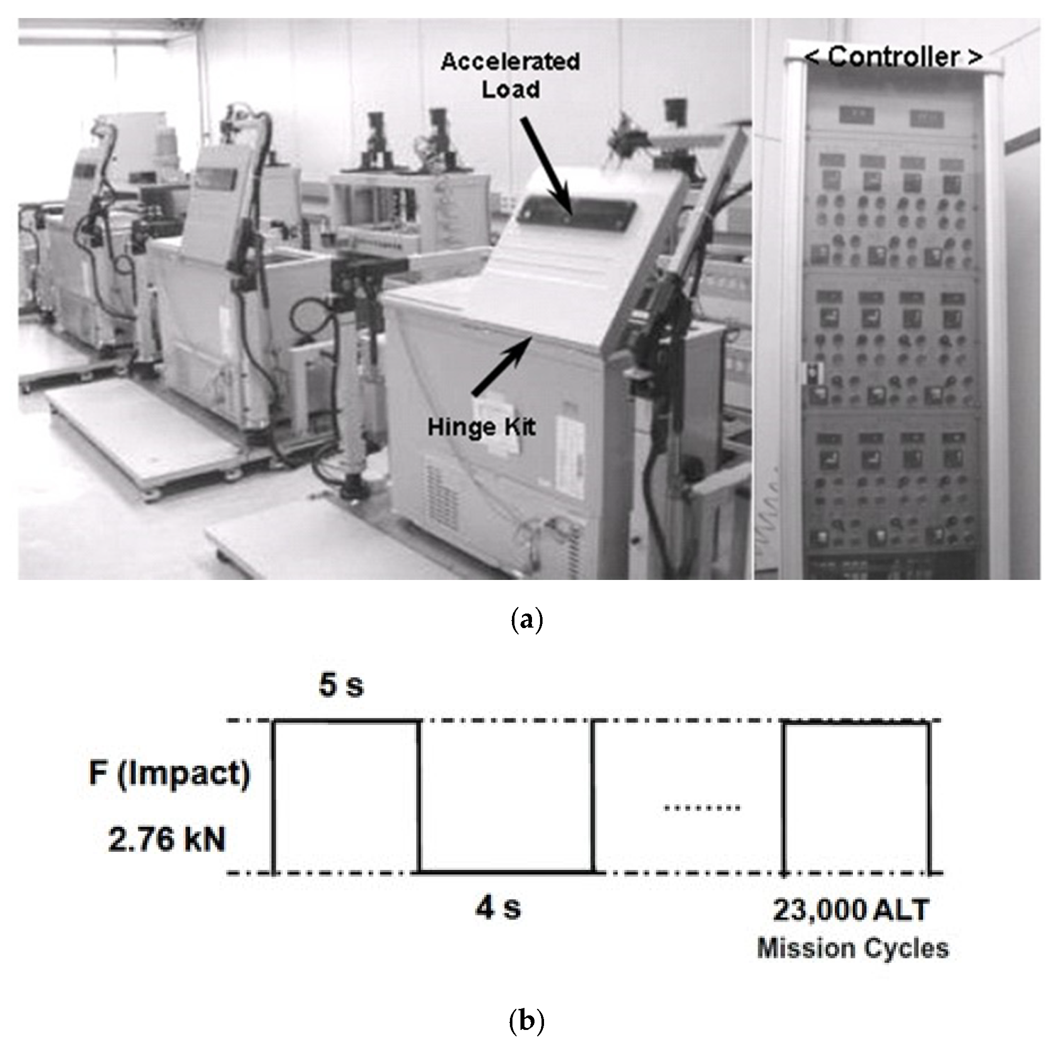
2.3. Parametric ALT of Mechanical Systems

To obtain the mission cycle of ALTs from the objective BX lifetime on the experiment scheme in Table 1, the sample size formulation integrated with the AF should be obtained [1]. Until now, numerous methodologies have been suggested to decide sample size. The Weibayes model for Weibull analysis is a popularly recognized method of examining reliability data. However, it is hard to directly use because of the mathematical complication. The whole cases as failures (r ≥ 1) and no failures (r = 0) need to be separated. Consequently, it is possible to acquire a comprehensible sample size equation that might provide the mission cycle after proper assumptions.
In choosing the model parameters to maximize the likelihood function, the maximum likelihood estimation (MLE) statistic is a widespread way of approximating the parameters of a model. The characteristic life ηMLE can be expressed as:
η M L E β = i = 1 n t i β r
where η M L E is the maximum likelihood estimate of the characteristic life, n is the total number of samples, t i is the test duration for each sample, and r is the number of failures.
If the number of failures is r ≥ 1 and the confidence level is 100(1 − α), the characteristic life, ηα, can be approximated from Equation (9),
η α β = 2 r χ α 2 ( 2 r + 2 ) × η M L E β = 2 χ α 2 ( 2 r + 2 ) × i = 1 n t i β for r 1
where χ α 2 () is the chi-square distribution when the p-value is α.
Assuming there are no number of failures, ln (1/α) is mathematically identical to the chi-square value, χ α 2 ( 2 ) 2 [46]. In other words,
p v a l u e : α = χ α 2 ( 2 ) ( e x 2 x ν 2 1 2 ν 2 Γ ( ν 2 ) ) d x = 2 ln α 1 ( e x 2 x ν 2 1 2 ν 2 Γ ( ν 2 ) ) d x for x 0
where Γ is the gamma function and ν is the shape parameter
For r = 0, the characteristic life ηα from Equation (10) can be defined as:
η α β = 2 χ α 2 ( 2 ) × i = 1 n t i β = 1 ln 1 α × i = 1 n t i β
As Equation (10) is proved for all cases r ≥ 0, characteristic life, ηα, can be expressed as follows:
η α β = 2 χ α 2 ( 2 r + 2 ) × i = 1 n t i β     for r 0
If the logarithm in the Weilbull distribution is taken, the connection between characteristic life and BX life, LB, can be defined as:
L B β = ( ln 1 1 x ) × η β
If the approximated characteristic life of the p-value α, ηα, in Equation (13), is changed into Equation (17), we obtain the BX life formulation:
L B β = ( ln 1 1 x ) × 2 χ α 2 ( 2 r + 2 ) × i = 1 n t i β
As nearly all life testing commonly has inadequate samples to approximate the lifetime for the assigned number of failures that might be less than that of the sample size, the plan testing time can begin as:
n h β t i β ( n r ) × h β
If Equation (16) is exchanged with Equation (15), the BX life equation can be redefined as:
L B β ( ln 1 1 x ) × 2 χ α 2 ( 2 r + 2 ) n h β ( ln 1 1 x ) × 2 χ α 2 ( 2 r + 2 ) × ( n r ) h β L B * β
If Equation (17) is rearranged, the sample size formulation with the failure numbers can be defined as:
n χ χ α 2 ( 2 r + 2 ) 2 × 1 ( ln 1 1 x ) × ( L B * h ) β + r
Because χ α 2 ( 2 r + 2 ) 2 ( r + 1 ) for α = 0.6 and ln ( 1 x ) 1 = x + x 2 2 + x 3 3 + x , the sample size Equation (21) can be simply close to:
n ( r + 1 ) × 1 x × ( L B * h ) β + r
where the sample size equation can be restated as n ~ (failure numbers + 1)⋅(1/cumulative failure rate)⋅((target lifetime/(plan testing time)) ^ β + r.
If Equation (8) is attached to the plan testing time h, Equation (19) can replaced as:
n ( r + 1 ) × 1 x × ( L B * A F h a ) β + r
If the lifetime target of a mechanical system such as the HKS in a domestic refrigerator is assigned to be B1 life 10 years, the mission cycles might be attained for an assigned set of samples subjected to the food loading. In ALTs, the design flaws of the new product might be recognized to fulfill the lifetime target [47,48,49].

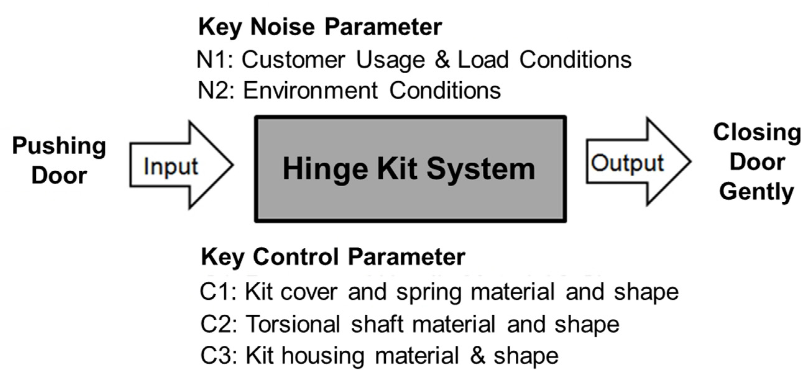
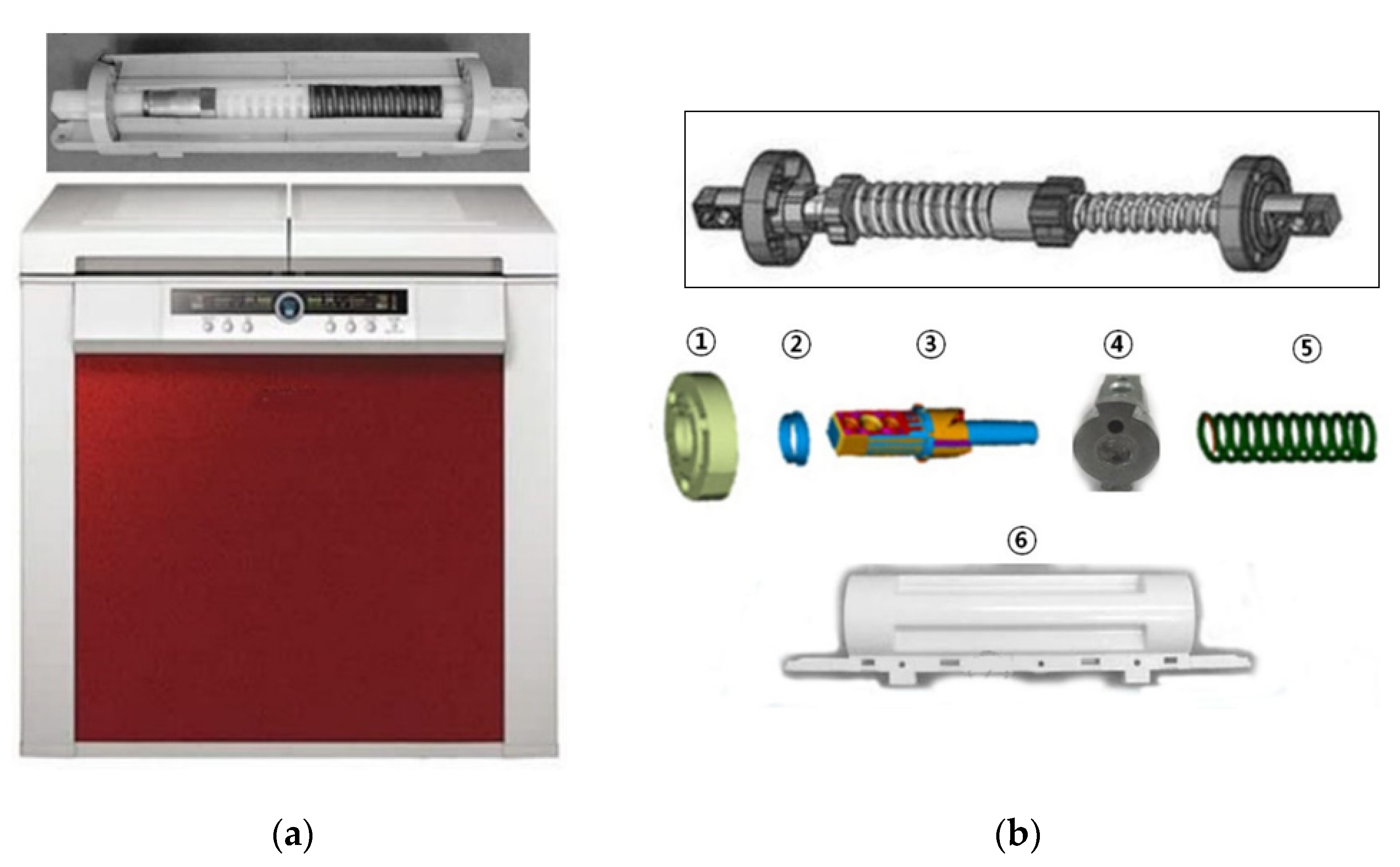
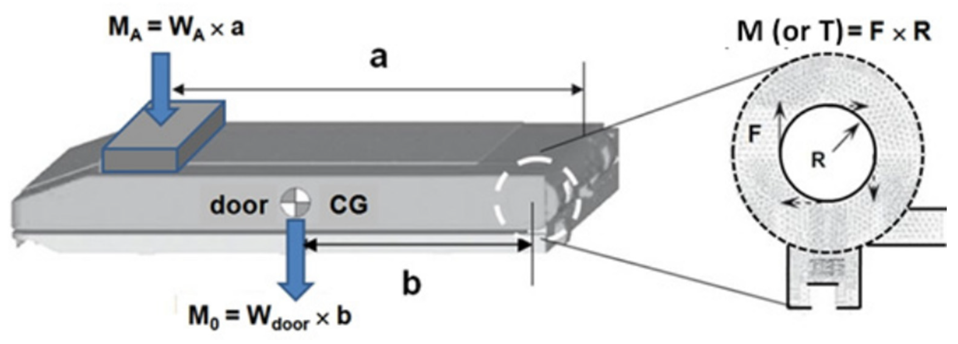
2.4. Case Study—Reliability Design of a Newly Designed HKS in Domestic Refrigerator

When a consumer operates a refrigerator door, they want to comfortably close the door. A new HKS was designed for the refrigerator (see Figure 5) to enhance the ease of opening and closing the door for the consumer. When opening/closing the door, the HKS was subjected to repeated impact loads over the lifetime of the domestic refrigerator. To endure the loads of the HKS, new metals—standard austenitic ductile iron (18 wt% Ni)—for the torsional shaft were a key metal component [50] used. Due to their cheap cost as well as outstanding workability, ductile cast irons have been utilized for numerous mechanical parts. They have fine monotonic strength and high ductility compared to malleable cast irons and gray cast irons. The fatigue strength of ductile cast irons is comparatively lower than those of the steels and alloys with the identical quantity of monotonic strength because of their distinctive microstructure holding graphite particles and casting defects [51]. The fatigue strength of a ductile cast iron in the current HKS design was evaluated through parametric ALT.
The HKS shown in Figure 5b consisted of a kit cover, torsional shaft (ductile iron), spring, and kit housing. To suitably work its function for a product lifetime, the HKS should be designed to endure the working circumstances subjected to it by the customers who utilize the refrigerator. In the Korean domestic market, the representative customer opened and closed the refrigerator door from three to ten times per day. Stocking food in the refrigerator had some repeated working procedures: (1) Open the door of refrigerator, (2) put the food into it, and then (3) close it. The HKS had different mechanical impact loadings when the customer utilized it.
The HKS in the marketplace had been fracturing, causing customers to demand the refrigerator be replaced. As subject to repeated impact stresses in using the refrigerator door, it was determined that the problematic HKS originated from several design defects. Market data also indicated that the returned products had crucial design problems on the structure, including stress risers—sharp corner angles and thin ribs. These design defects prohibited the HKS from enduring the repeated impact loads during the openings/closings and resulted in a crack that propagated to its end. The HKS was originally designed to endure repeated impact loading under customer working conditions (Figure 6).
When customers operated the refrigerator door, they could take out and put in food. Relying on the end-user working conditions, the HKS experienced repeated impact loading in the process. To correctly work the HKS, many mechanical structural parts in the HKS assembly needed to be designed robustly. As the concentrated stress in the mechanical system was revealed at stress raisers such as sharp corner angles, it was crucial to demonstrate these design flaws experimentally. As a result, engineers could then modify the design.
As seen in Figure 7, from the functional design ideas of a mechanical HKS, we knew that the impact force on the HKS came from the door weight. That is, the moment balance around HKS can be stated as
M 0 = W d o o r × R
( 2 1 ) = T 0 = F 0 × R
where b is distance from the HKS to the center of gravity (CG) of the door.
To increase the impact on the HKS, additional accelerated weight was added. The moment balance around the HKS with an accelerated weight can be stated as
M 1 = M 0 + M A = W d o o r × b + M A × a
( 23 ) = T 1 = F 1 × R
where a is distance from the HKS to the accelerated weight
Because the time to failure depended on the impact force due to moment, the impact was controlled during the accelerated life testing. Under the same working conditions, the life-stress model (LS model) in Equation (7) can be restated as
T F = A ( S ) n = A T λ = A ( F × R ) λ = B ( F ) λ
where A and B are constant
Therefore, the AF in Equation (8) can be restated as
A F = ( S 1 S 0 ) n = ( T 1 T 0 ) λ = ( F 1 F 0 ) λ
For a refrigerator including the HKS, the environmental (or working) customer conditions were roughly 0–43 °C with a relative humidity varying from 0 to 95%, and 0.2–0.24 g of acceleration. As previously mentioned, the number of openings/closings of the HKS per day varied from 3 to 10 times. With a design criterion of a product lifetime for 10 years, L B * , the HKS has 36,500 usage cycles in the worst case.
Under a lifetime target—B1 life 10 years—if the number of lifetime cycles L B * and AF are computed for the assigned sample size, the actual mission cycles, ha, might be acquired from Equation (20). Then, the ALT equipment can be made and performed in accordance with the working course of the HKS. Through parameter ALTs, the design missing parameters (or design flaws) for the new mechanical system can be identified.
The greatest impact force due to the door weight exerted by the customer in utilizing the refrigerator, F1, was 1.1 kN. To determine the stress level for ALT, we used the step-stress life test that can assess the lifetime under constant used-condition for various accelerated weights [52]. As the stress level to a different level was changed, the failure times of the HKS at a particular stress level was observed. Finally, for an ALT with an accelerated weight, we determined that the exerted impact force, F2, was 2.76 kN. With a cumulative damage exponent, λ, of 2, the AF was 6.3 from Equation (26). To obtain the missing design parameters of a newly designed HKS, a lifetime target should be more than B1 life 10 years. If the shape parameter β was 2.0, the number of test cycles computed from Equation (20) would be 23,000 cycles for 6 sample units. If the parametric ALT failed less than once for 23,000 cycles, the lifetime for the HKS would be assured to be B1 life 10 years (Figure 8).
The control console was used to run the testing apparatus—the number of test cycles, beginning or ending the equipment, etc. As the start knob on the controller console gave the starting signal, the straight hand-shaped arms clasped and raised the refrigerator door. When the door was shut, it was exerted to the HKS with the greatest mechanical impact force due to the accelerated load (2.76 kN).

3. Results and Discussion

In the 1st ALT, the housing of the HKS failed at 3000 cycles. Figure 9 shows the failed product from the marketplace and the 1st ALT. Upon carefully observing the failure locations from the marketplace and the first ALT, it was found that the failures were around the housing and its support in the HKS structure as a consequence of high impact stress.
Figure 10 provides a graphical presentation of the 1st ALT results and the failure data from the field shown on the Weibull plot. As the two patterns had similar slopes on the plot, each loading state of the 1st ALT and the field over the product lifetime were alike under the operational conditions of customers. Thus, it should be expected that the test samples will fail like those in the field. For the shape parameter, β, the final shape parameter from the chart was affirmed to be 2.0, compared with the estimated value—2.0. Based on both test results in the Weibull plot, the parametric ALT was effective because it identified the design flaws that were accountable for the field failures. In other words, as substantiated by two items—the visual representation in the pictures and similar slopes in the Weibull plot—these systematic methods were well-founded in identifying the problematic designs that accounted for the failures from the field. These failures decided the product (refrigerator’s) lifetime.
Due to the design defect of no support in the high-stress areas, the repeated impact loading in conjunction with this structural defect may have produced fracturing of the HKS housing. This design defect can be altered by adding the support ribs, C1 (Figure 11). Stress analysis, which can be combined with fatigue analysis and parametric ALT, was carried out by using a finite element analysis (FEA). When the HKS was fixed against the wall (or surface) as the boundary conditions, the straightforward impact loads, as seen in Figure 7, were applied. Using materials and processing conditions similar to those of the finished HKS, the constitutive properties of the materials such as HIPS (HKS housing) were determined. The maximum stresses for the old and new designs were estimated separately. Based on these results, the appropriateness of the current designs for the HKS housing was evaluated. After modifying the new designs to improve the design against fatigue, the estimated stress concentrations in the HKS housing decreased from 21.2 to 15.0 MPa using the FEM analysis. It was expected that this new design should be effective in reducing fatigue failure of the HKS housing when subjected to repeated load under the consumer usage conditions.
With the confirmed shape parameter β of 2.0, the real mission cycles computed from Equation (20) were 23,000 cycles for the six sample units. If the HKS failed at less than once for 23,000 cycles, its lifetime would be assured to be B1 life 10 years. As seen in Figure 12, in the second ALT, from the outside corner, the torsional shaft in the HKS that was made of ductile iron failed at 12,000 cycles. Such ductile cast iron accounts for a major family of metals that are extensively used for gears, automobile crankshafts, dies, and numerous machine parts because of its good machinability, fatigue strength, and high modulus of elasticity. They have a mass fraction (%) as follows: Carbon (3.0–3.7), silicon (1.2–2.3), manganese (0.25), magnesium (0.07), phosphorus (0.03) [53].
When closely examining the product failure in the 2nd ALT, the torsional shaft in the HKS had insufficient strength to endure the repeated impact loading of the opening/closing of the door. When subjected to repeated impact loads, the stress amplification of mechanical components such as the torsional shaft in the HKS not only occurred at minute defects or cracks on a microscopic level of material but could also happen in stress concentrations such as in sharp corners, fillets, holes, and notches on the macroscopic range that are normally explained as stress raisers. For example, the stress concentration at the sharp-edged corners depended on fillet radius [54]. To improve the design, the torsional shaft was altered by giving it more rounding from R0.5 mm to R2.0 mm, C2 (Figure 12).
For the HKS upgrade, the design basis of new samples was determined to be more than the lifetime target—B1 life 10 years. To confirm the design of the HKS, a 3rd ALT was performed. As the affirmed value, β, on the Weibull plot was 2.0, for the lifetime target—B1 life 10 years—the actual mission cycles in Equation (20) were 23,000 for the six-sample size. In the third ALT, there were no design issues in the HKS until the experiment reached 23,000 cycles. It was therefore concluded that the altered design parameters obtained from the 1st and 2nd ALTs were successful.
Table 3 provides a summary of the ALT results. With the alternative designs, the HKS was assured to have a lifetime target—B1 life 10 years. That is, we knew that the product would have 99% reliability (or 1% unreliability) for 10 years with a yearly failure rate of 0.1%.

4. Conclusions

A systematic reliability method was proposed for a new mechanical system such as an HKS in refrigerators. It incorporated: (1) A parametric ALT plan formed on product BX lifetime, (2) a load examination for ALT, (3) customized ALTs with the design alterations, and (4) an assessment of whether the last design(s) of the product fulfilled the objective BX lifetime. Testing was conducted to subject the HKS in the domestic refrigerator to repeated impact loading.
In the first ALT, the HKS housing had insufficient strength for repeated impact loading and cracked. As an action plan, these flaws in the HKS were corrected by adding supporting ribs. In the second ALT, the torsional shaft made of ductile iron cracked. Due to its good machinability, fatigue strength, and high modulus of elasticity, iron is widely used in machine components. To improve its strength for impact loading, the torsional shaft was altered by increasing the corner roundness.
With these altered design parameters, in the third ALT, there were no design issues. The altered design parameters were assured to satisfy the lifetime need of the HKS—B1 life 10 years. With the examination of returned products from the marketplace, laboratory load evaluations and testing, and parametric ALTs with design modifications, the design flaws were identified and remedied to create a robust design with a remarkably lengthy lifetime. This parametric ALT is also recommended to be applied to other metals that can be used in the numerous machine parts such as cam, gears, automobile crankshafts, and dies [55,56,57,58,59].

Author Contributions

S.W. conducted the conceptualization, methodology, analysis, and testing and wrote the article. D.L.O. checked the analysis and writing for original draft. M.M.T. and S.M.A. review and edit the paper. D.E.W. supervised the research and paper preparation. All authors have read and agreed to the published version of the manuscript.

Funding

This research received no external funding.

Institutional Review Board Statement

Not applicable.

Informed Consent Statement

Not applicable.

Data Availability Statement

The data presented in this study are available on request from the corresponding author.

Conflicts of Interest

The authors state no conflicts of interest.

Abbreviations

BXtime that is an accumulated failure rate of X%: durability index
Eaactivation energy, eV
eeffort
fflow
Fimpact force, kN
F(t)unreliability
htesting cycles (or cycles)
h*
J
nondimensional testing cycles, h * = h / L B 1
junction equation
kBoltzmann’s constant, 8.62 × 10⁻⁵ eV/deg
LB
M
target BX life and x = 0.01X, on the condition that x ≤ 0.2
moment around the hinge kit system, kN× m
Nnumber of test samples
Qamount of energy absorbed or released during the reaction. For the semiconductor total number of dopants per unit area
R
R
r
radius of the hinge kit system, m
ratio for minmum stress to maximum stress in stress cycle, σminmax
failed numbers
Sstress
T
T
ti
torque around the hinge kit system, kN⋅ m
temperature, K
test time for each sample
TFtime to failure
Xaccumulated failure rate, %
x
WA
Wdoor
x = 0.01X, on condition that x ≤ 0.2.
accelerator weight, kg
door weight, kg
Greek symbols
ξelectrical field applied
ηcharacteristic life
λ
χ2
α
cumulative damage exponent in Palmgren–Miner’s rule
chi-square distribution
confidence level
Superscripts
βshape parameter in Weibull distribution
nstress dependence, n = [ ln ( T f ) ln ( S ) ] T
Subscripts
0normal stress conditions
1accelerated stress conditions

References

  1. Woo, S.; Pecht, M.; O’Neal, D. Reliability design and case study of the domestic compressor subjected to repetitive internal stresses. Reliab. Eng. Syst. Saf. 2020, 193, 106604. [Google Scholar] [CrossRef]
  2. Deming, W.E. Elementary Principles of the Statistical Control of Quality; Japan JUSE: Hyatt Regency, Tokyo, 1950. [Google Scholar]
  3. CMMI Product Team. Capability Maturity Model Integration (CMMI) Version 2,0, Continuous Representation; Report CMU/SEI-2002-TR-011; Software Engineering Institute: Pittsburgh, PA, USA, 2018. [Google Scholar]
  4. NASA. System Engineering Handbook; NASA/SP-2020-6105 Rev 2; NASA Headquarters: Washington, DC, USA, 2020; p. 92. [Google Scholar]
  5. Cengel, Y.A.; Boles, M.A. Thermodynamics: An Engineering Approach, 9th ed.; McGraw-Hill: New York, NY, USA, 2018. [Google Scholar]
  6. Magaziner, I.C.; Patinkin, M. Cold competition: GE wages the refrigerator war. Harv. Bus. Rev. 1989, 89, 114–124. [Google Scholar]
  7. WRDA 2020 Updates. The Final Report of the US House Committee on Transportation and Infrastructure on the Boeing 737 Max. Available online: https://transportation.house.gov/committee-activity/boeing-737-max-investigation (accessed on 16 September 2020).
  8. Chowdhury, S.; Taguchi, S. Robust Optimization: World’s Best Practices for Developing Winning Vehicles, 1st ed.; John Wiley & Sons Inc.: Hoboken, NJ, USA, 2016. [Google Scholar]
  9. Montgomery, D. Design and Analysis of Experiments, 10th ed.; John Wiley: Hoboken, NJ, USA, 2020. [Google Scholar]
  10. ASTM E606/E606M. Standard Test Method for Strain-Controlled Fatigue Testing; ASTM International: West Conshohocken, PA, USA, 2019. [Google Scholar]
  11. ASTM E399. Standard Test Method for Linear-Elastic Plane-Strain Fracture Toughness of Metallic Materials; ASTM International: West Conshohocken, PA, USA, 2020. [Google Scholar]
  12. ASTM E647. Standard Test Method for Measurement of Fatigue Crack Growth Rates; ASTM International: West Conshohocken, PA, USA, 2015. [Google Scholar]
  13. ASTM E739-10. Standard Practice for Statistical Analysis of Linear or Linearized Stress-Life (S-N) and Strain-Life (ε-N) Fatigue Data; ASTM International: West Conshohocken, PA, USA, 2015. [Google Scholar]
  14. Braco, R.; Prates, P.; Costa, J.D.M.; Berto, F. New methodology of fatigue life evaluation for multiaxially loaded notched components based on two uniaxial strain-controlled tests. Int. J. Fatigue 2018, 111, 308–320. [Google Scholar] [CrossRef]
  15. Modarres, M.; Kaminskiy, M.; Krivtsov, V. Reliability Engineering and Risk Analysis: A Practical Guide, 3rd ed.; CRC Press: Boca Raton, FL, USA, 2016. [Google Scholar]
  16. Wang, L.; Li, Y. Boundary for aviation bearing accelerated life test based on quasi-dynamic analysis. Tribol. Int. 2017, 116, 414–421. [Google Scholar] [CrossRef]
  17. Zaharia, S.M. The methodology of fatigue lifetime prediction and validation based on accelerated reliability testing of the rotor pitch links. Eksploat. Niezawodn. 2019, 2, 638–644. [Google Scholar] [CrossRef]
  18. Chang, M.S.; Lee, C.S.; Choi, B.O.; Kang, B.S. Study on validation for accelerated life tests of pneumatic cylinders based on the test results of normal use conditions. J. Mech. Sci. Technol. 2017, 31, 2739–2745. [Google Scholar] [CrossRef]
  19. Koo, H.J.; Kim, Y.K. Reliability assessment of seat belt webbings through accelerated life testing. Polym. Test. 2005, 24, 309–315. [Google Scholar] [CrossRef]
  20. Özsoy, S.; Çelik, M.; Kadıoğlu, F.S. An accelerated life test approach for aerospace structural components. Eng. Fail. Anal. 2008, 15, 946–957. [Google Scholar] [CrossRef]
  21. Nakada, M.; Miyano, Y. Accelerated testing for long-term fatigue strength of various FRP laminates for marine use. Compos. Sci. Technol. 2009, 69, 805–813. [Google Scholar] [CrossRef]
  22. Miyano, Y.; Nakada, M.; Ichimura, J.; Hayakawa, E. Accelerated testing for long-term strength of innovative CFRP laminates for marine use. Compos. Part B Eng. 2008, 39, 5–12. [Google Scholar] [CrossRef]
  23. Rajaneesh, A.; Satrio, W.; Chai, G.B.; Sridhar, I. Long-term life prediction of woven CFRP laminates under three point flexural fatigue. Compos. Part B Eng. 2016, 91, 539–547. [Google Scholar] [CrossRef]
  24. Bank, L.C.; Gentry, T.R.; Barkatt, A. Accelerated Test Methods to Determine the Long-Term Behavior of FRP Composite Structures: Environmental Effects. J. Reinf. Plast. Compos. 1995, 14, 559–587. [Google Scholar] [CrossRef]
  25. Elsayed, E.A. Reliability Engineering; Addison Wesley Longman: Boston, MA, USA, 1996. [Google Scholar]
  26. Hahn, G.J.; Meeker, W.Q. How to Plan an Accelerated Life Test (E-Book); ASQ Quality Press: Milwaukee, WI, USA, 2004. [Google Scholar]
  27. McPherson, J. Accelerated testing. In Electronic Materials Handbook Volume 1: Packaging; ASM International Publishing: Materials Park, OH, USA, 1989; pp. 887–894. [Google Scholar]
  28. McPherson, J. Reliability Physics and Engineering: Time-to-Failure Modeling; Springer: New York, NY, USA, 2010. [Google Scholar]
  29. Griffith, A.A. The phenomena of rupture and flow in solids. Philos. Trans. R Soc. Lond. A 1921, 221, 163–198. [Google Scholar]
  30. Irwin, G. Analysis of stresses and strains near the end of a crack traversing a plate. J. Appl. Mech. 1957, 24, 361–364. [Google Scholar]
  31. Anderson, T.L. Fracture Mechanics—Fundamentals and Applications, 3rd ed.; CRC: Boca Raton, FL, USA, 2017. [Google Scholar]
  32. Neuber, H. Theory of stress concentration for shear strained prismatical bodies with arbitrary non-linear stress-strain law. J. Appl. Mech. 1961, 28, 544–550. [Google Scholar] [CrossRef]
  33. Goodno, B.J.; Gere, J.M. Mechanics of Materials, 9th ed.; Thomson Brooks Cole Learning: Boston, MA, USA, 2020. [Google Scholar]
  34. Hertzberg, R.W.; Vinci, R.P.; Hertzberg, J.L. Deformation and Fracture Mechanics of Engineering Materials, 6th ed.; John Wiley and Sons Inc.: Hoboken, NJ, USA, 2020. [Google Scholar]
  35. Reddy, J.N. An Introduction to the Finite Element Method, 4th ed.; McGraw-Hill: New York, NY, USA, 2020. [Google Scholar]
  36. Courant, R. Variational methods for the solution of problems of equilibrium and vibrations. Bull. Am. Math. Soc. 1943, 49, 1–23. [Google Scholar] [CrossRef] [Green Version]
  37. Matsuishi, M.; Endo, T. Fatigue of metals subjected to varying stress. Jpn. Soc. Mech. Eng. 1968, 68, 37–40. [Google Scholar]
  38. Janssens, K.G.F. Universal cycle counting for non-proportional and random fatigue loading. Int. J. Fatigue 2020, 133, 105409. [Google Scholar] [CrossRef]
  39. Palmgren, A.G. Die Lebensdauer von Kugellagern. Z Ver Dtsch Ing. 1924, 68, 339–341. [Google Scholar]
  40. IEEE Standard Glossary of Software Engineering Terminology. IEEE STD 610.12-1990. Standards Coordinating Committee of the Computer Society of IEEE. (reaffirmed September 2002). Available online: https://ieeexplore.ieee.org/document/159342 (accessed on 31 December 1990).
  41. Klutke, G.; Kiessler, P.C.; Wortman, M.A. A critical look at the bathtub curve. IEEE Trans. Reliab. 2015, 52, 125–129. [Google Scholar] [CrossRef]
  42. Kreyszig, E. Advanced Engineering Mathematics, 10th ed.; John Wiley and Son: Hoboken, NJ, USA, 2011; p. 683. [Google Scholar]
  43. Grove, A. Physics and Technology of Semiconductor Device, 1st ed.; Wiley International Edition: New York, NY, USA, 1967; p. 37. [Google Scholar]
  44. Minges, M.L. Electronic materials handbook; ASM International: Cleveland, OH, USA, 1989; Volume 1, p. 888. [Google Scholar]
  45. Karnopp, D.C.; Margolis, D.L.; Rosenberg, R.C. System Dynamics: Modeling, Simulation, and Control of Mechatronic Systems, 6th ed.; John Wiley & Sons: New York, NY, USA, 2012. [Google Scholar]
  46. Abernethy, R.B. The New Weibull Handbook; Reliability Analysis Center: North Palm Beach, FL, USA, 2000; pp. 6–12. [Google Scholar]
  47. Woo, S.; Pecht, M. Failure analysis and redesign of a helix upper dispenser. Eng Fail Anal. 2008, 15, 642–653. [Google Scholar] [CrossRef]
  48. Woo, S.; O’Neal, D.; Pecht, M. Design of a hinge kit system in a Kimchi refrigerator receiving repetitive stresses. Eng. Fail. Anal. 2009, 16, 1655–1665. [Google Scholar] [CrossRef]
  49. Woo, S.; O’Neal, D.; Pecht, M. Failure analysis and redesign of the evaporator tubing in a Kimchi refrigerator. Eng. Fail. Anal. 2010, 17, 369–379. [Google Scholar] [CrossRef]
  50. ASTM A439/A439M–18. Standard Specification for Austenitic Ductile Iron Castings; ASTM International: West Conshohocken, PA, USA, 2018. [Google Scholar]
  51. Nadot, Y.; Mendez, J.; Ranganathan, N. Influence of casting defects on the fatigue limit of nodular cast iron. Int. J. Fatigue 2004, 26, 311–319. [Google Scholar] [CrossRef]
  52. Tang, L.C. Multiple-steps Step-stress Accelerated Life Test. In Handbook of Reliability Engineering; Springer: London, UK, 2003; Chapter 24; pp. 441–455. [Google Scholar]
  53. ASTM A874/A874M-98. Standard Specification for Ferritic Ductile Iron Castings Suitable for Low-Temperature Service; ASTM International: West Conshohocken, PA, USA, 2018. [Google Scholar]
  54. Neugebauer, G.H. Stress concentration factors and their effect in design. Prod. Eng. NY A 1943, 14, 82–87. [Google Scholar]
  55. Cinkilic, E.; Yan, X.; Luo, A.A. Modeling Precipitation Hardening and Yield Strength in Cast Al-Si-Mg-Mn Alloys. Metals 2020, 10, 1356. [Google Scholar] [CrossRef]
  56. Szymczak, T.; Gumienny, G.; Klimek, L.; Goły, M.; Pacyniak, T. Microstructural Characteristics of AlSi9Cu3(Fe) Alloy with High Melting Point Elements. Metals 2020, 10, 1278. [Google Scholar] [CrossRef]
  57. Li, Q.; Xie, L. Analysis and Optimization of Tooth Surface Contact Stress of Gears with Tooth Profile Deviations, Meshing Errors and Lead Crowning Modifications Based on Finite Element Method and Taguchi Method. Metals 2020, 10, 1370. [Google Scholar] [CrossRef]
  58. Miao, X.; Liu, X.; Lu, P.; Han, J.; Duan, W.; Wu, M. Influence of Scanning Strategy on the Performances of GO-Reinforced Ti6Al4V Nanocomposites Manufactured by SLM. Metals 2020, 10, 1379. [Google Scholar] [CrossRef]
  59. Raja, A.; Chukka, S.T.; Jayaganthan, R. Prediction of Fatigue Crack Growth Behavior in Ultrafine Grained Al 2014 Alloy Using Machine Learning. Metals 2020, 10, 1349. [Google Scholar] [CrossRef]
Figure 1. Product lifetime with multi-modules decided by newly designed module (a) Classification of multi-module refrigerator; (b) Product lifetime LB and failure rate λs.
Metals 11 00139 g001
Figure 2. Bathtub curve and straight line.
Metals 11 00139 g002
Figure 3. Parameter diagram of hinge kit system (HKS) (example).
Metals 11 00139 g003
Figure 4. Fatigue failure on the product produced by (random) repeated load and design flaws.
Metals 11 00139 g004
Figure 5. A domestic refrigerator (a) and HKS (b) and its parts: (1) kit cover, (3) support, (4) torsional shaft (cast iron), (5) spring, and (6) kit housing (high-impact polystyrene, HIPS).
Metals 11 00139 g005
Figure 6. Damaged HKS in field after use.
Metals 11 00139 g006
Figure 7. Functional design ideas of a mechanical HKS.
Metals 11 00139 g007
Figure 8. ALT (a) equipment; (b) duty cycles of repeated impact load F.
Metals 11 00139 g008
Figure 9. Failed HKS from the marketplace and in the first ALT: (a) Failed product after first ALT; (b) product with crack in field.
Metals 11 00139 g009
Figure 10. Market data and outcomes of 1st ALT on Weibull plot.
Metals 11 00139 g010
Figure 11. Failed HKS housing in the first ALT: (a) Its root cause; (b) design modifications.
Metals 11 00139 g011
Figure 12. Root cause and design modification of cracked torsional shaft (cast iron) in the second ALT: (a) Root cause; (b) design modification.
Metals 11 00139 g012
Table 1. Whole ALT plan of mechanical system such as modules in a refrigerator.
ModulesMarket DataExpected ReliabilityTargeted Reliability
Yearly Failure Rate, %/YearBX Life, YearYearly Failure Rate, %/YearBX Life, YearYearly Failure Rate, %/YearBX Life, Year
A0.352.9Similar×10.352.90.1010(BX = 1.0)
B0.244.2New×51.200.830.1010(BX = 1.0)
C0.303.3Similar×10.303.330.1010(BX = 1.0)
D0.313.2Modified×20.621.610.1010(BX = 1.0)
E0.156.7Modified×20.303.330.1010(BX = 1.0)
Others0.5010.0Similar×10.5010.00.5010(BX = 5.0)
Product1.92.9--3.270.831.0010(BX = 10)
Table 2. Power definition in a multi-port system.
SystemEffort, e(t)Flow, f(t)
Mechanical translationForce, F(t)Velocity, V(t)
Mechanical rotationTorque, τ(t)Angular velocity, ω(t)
Compressor, PumpPressure difference, ΔP(t)Volume flow rate, Q(t)
ElectricVoltage, V(t)Current, i(t)
MagneticMagneto-motive force, emMagnetic flux, φ
Table 3. Results of ALTs.
Parametric ALT1st ALT2nd ALT3rd ALT
Initial DesignSecond DesignLast Design
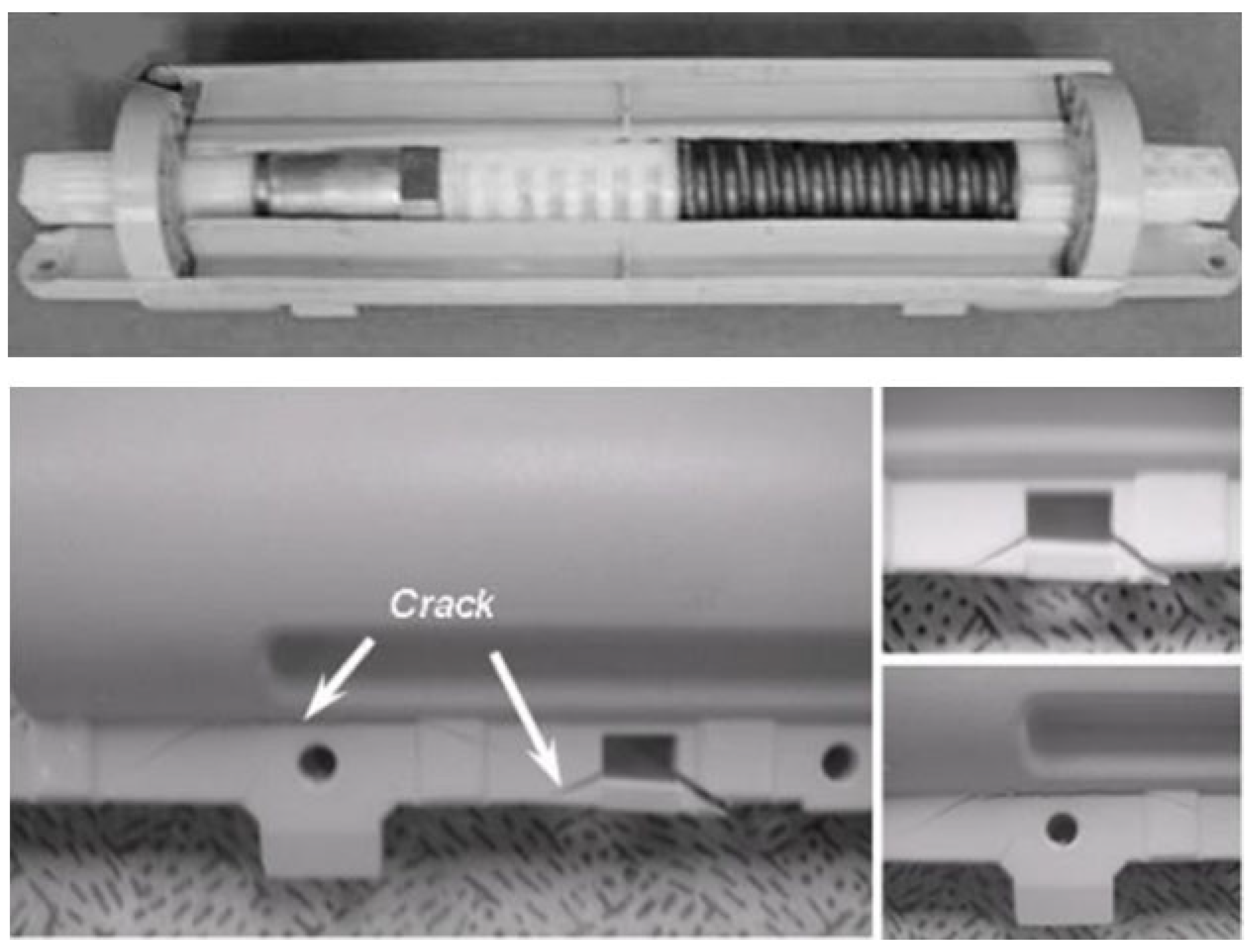
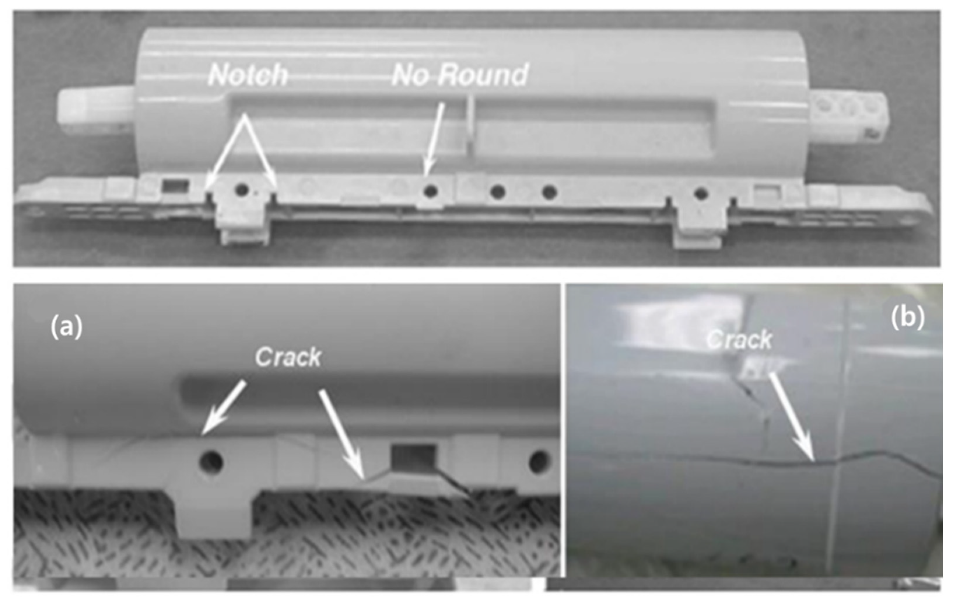
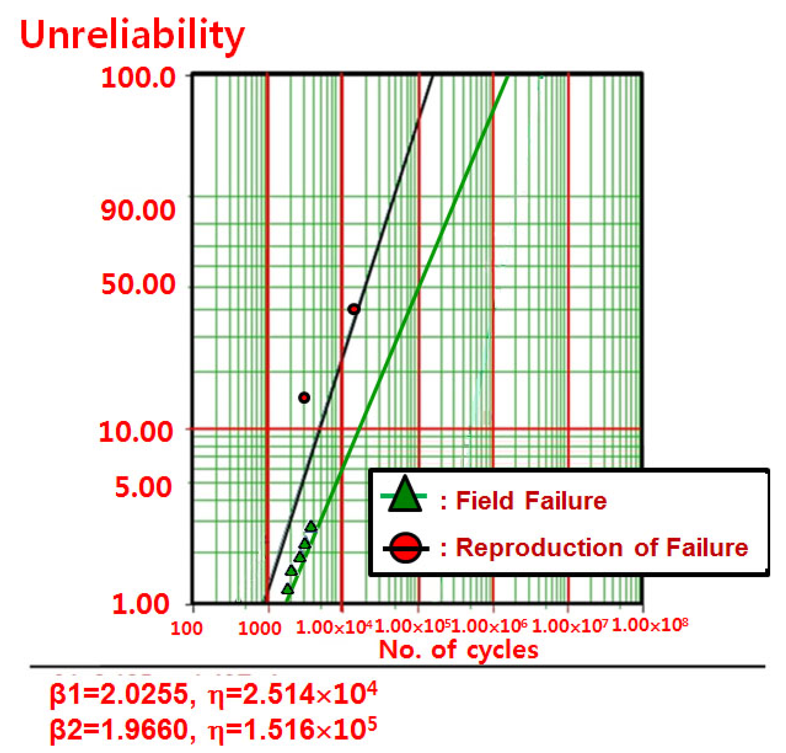
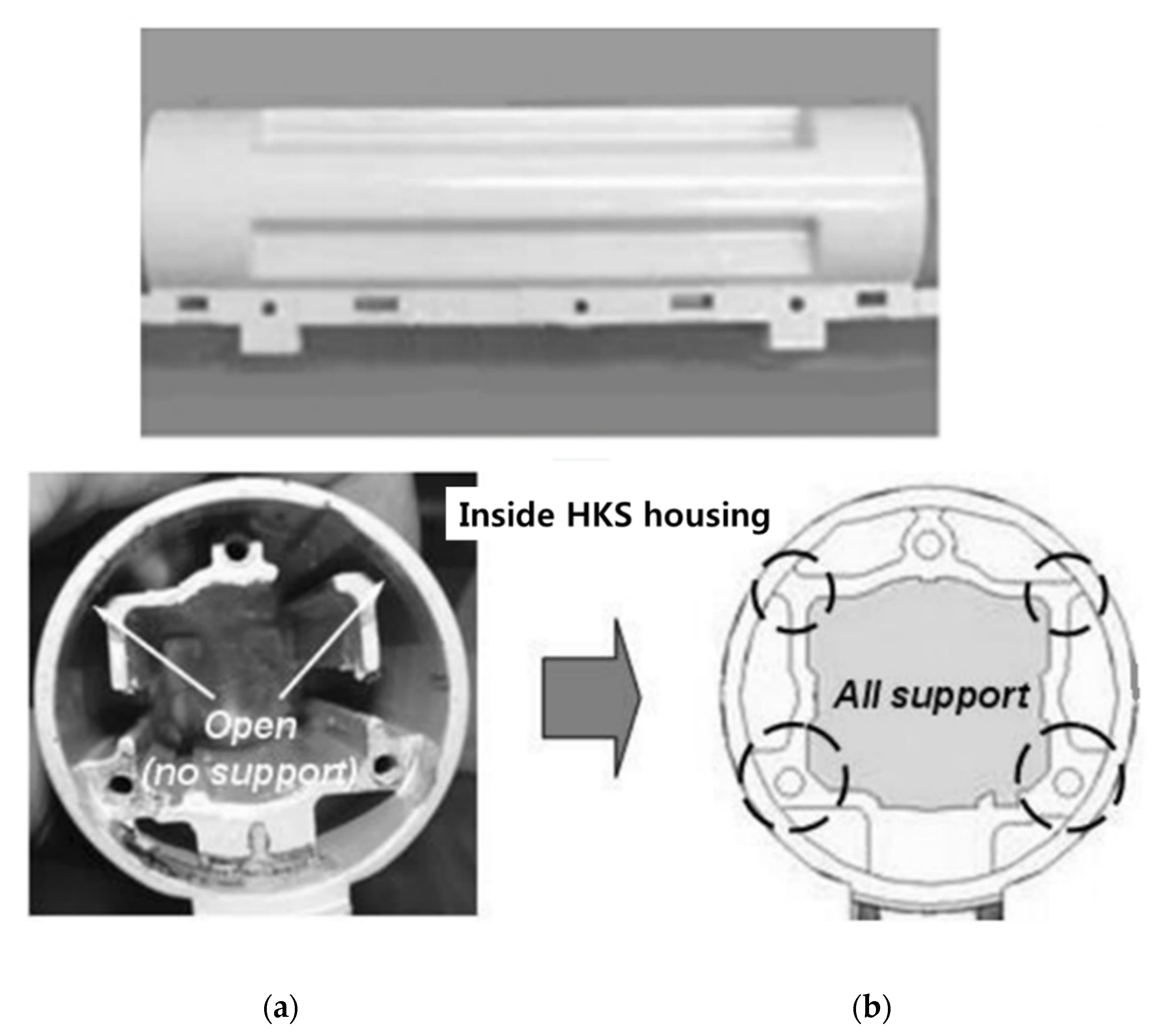
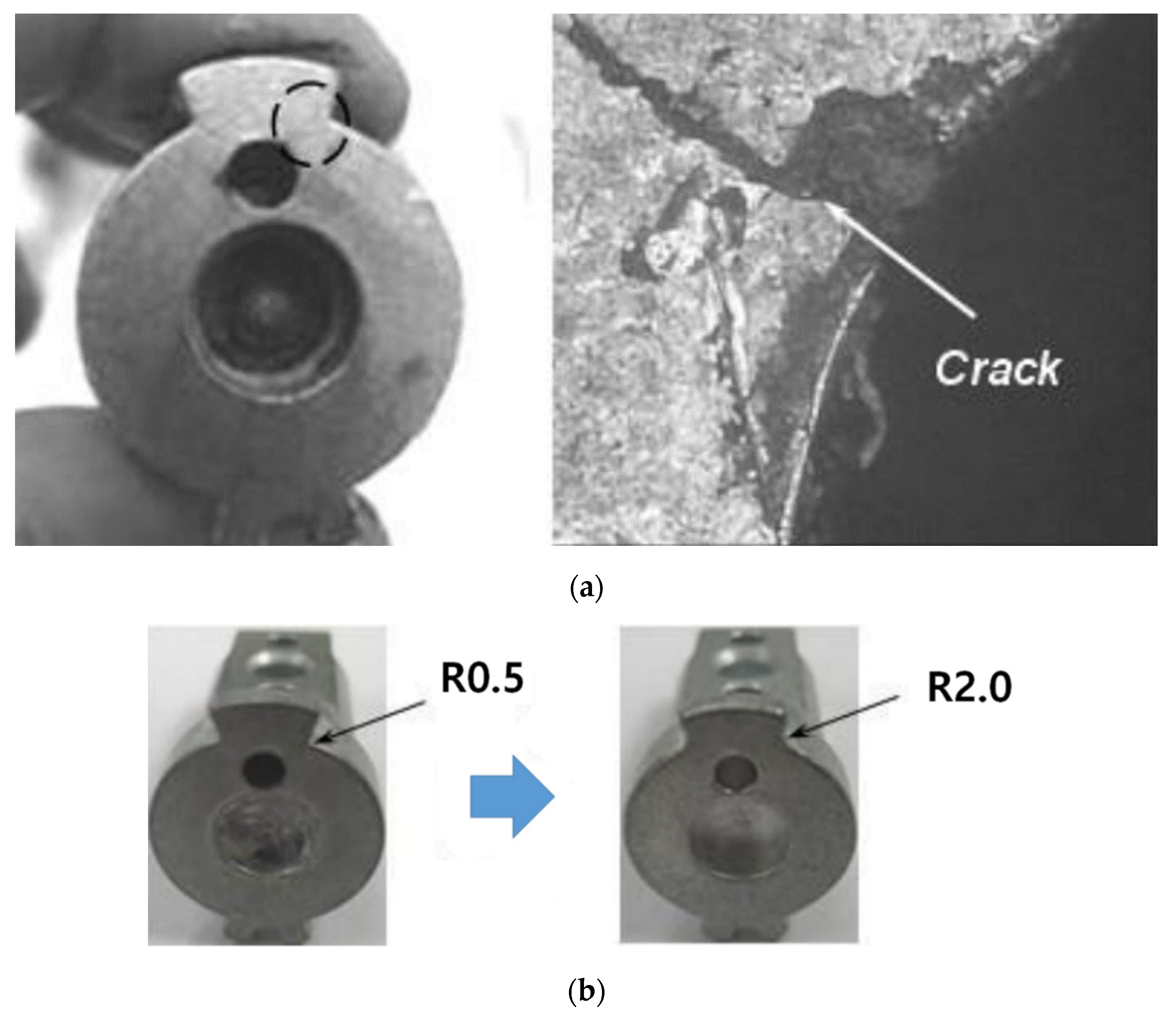
In 23,000 cycles, there are no problems in the HKS3000 cycles: 2/6 Fracture
(HKS Housing)
12,000 cycles: 4/6 crack
(Torsional Shaft)
23,000 cycles:6/6 OK
41,000 cycles:6/6 OK
HKS Structure Metals 11 00139 i001 Metals 11 00139 i002-
Action plansC1: No → 2 support ribsC2: R0.5mm → R2.0mm
Roundness corner of torsional shaft
-
Publisher’s Note: MDPI stays neutral with regard to jurisdictional claims in published maps and institutional affiliations.

