Article

Numerical Analysis of Radiative Heat Transfer and Direct Reduction of Three-Dimensional Multilayer Ellipsoidal Carbon-Containing Pellet Unit in the Rotary Hearth Furnace

1
School of Energy and Power Engineering, Chongqing University, Chongqing 400044, China
2
Key Laboratory of Low-grade Energy Utilization Technologies and Systems, Chongqing University, Ministry of Education, Chongqing 400044, China
*
Author to whom correspondence should be addressed.
Metals 2020, 10(8), 994; https://doi.org/10.3390/met10080994
Submission received: 3 June 2020 / Revised: 20 July 2020 / Accepted: 21 July 2020 / Published: 23 July 2020
(This article belongs to the Special Issue Numerical Modelling in Steel Metallurgy)

Abstract

:
It is very important for a multilayer pellet bed to have a proper description of the radiant heat transfer and direct reduction process in the rotary hearth furnace. Ellipsoidal pellets may also be used in industrial production. The research on this ellipsoidal pellet bed will provide comprehensive data support for the production process. Besides, the view factor is one of the important factors affecting the heat transfer of the multilayer pellet bed. It is of great significance to study its value and distribution. In this study, the effects of the gas field and the bottom of the furnace on the direct reduction of multilayer ellipsoidal pellets were considered. The local environmental viewing angle coefficient in the model was obtained through the mechanism calculation method, which is more accurate than the calculation through the radiation exchange network. Furthermore, the porosity variation in the pellet during the direct reduction process was also considered. According to the calculation, it was found that the higher initial temperature at the furnace bottom is beneficial to increase the degree of metallization (DOM) and zinc removal rate (ZRR) for all pellets, and is more advantageous to the lower pellets in the material bed. Nevertheless, the reduction degree of the lower pellets is still smaller than that of the upper pellets. The results also show that increasing the offset ξ has a greater effect on increasing the ambient view factor and each position reduction degree in the ellipsoidal pellets layer. Results can be applied for the optimization of pellets distribution in a rotary hearth furnace.

1. Introduction

With the development of society and the consumption of resources, the demand for sustainable recycling methods is increasing. Among them, the demand for efficient recovery of metallurgical and ironmaking dust has also continuously prompted scholars from various countries to invest in this research area. Nowadays, the direct reduction process based on rotary hearth furnace (RHF) has attracted great attention from researchers due to its high carbon utilization rate, low CO2 emissions, and low energy consumption [1,2]. The use of a rotary hearth furnace (RHF) can effectively process these metallurgical dust powders while achieving sustainable development of the environment and economy [3,4,5]. However, the multilayer pellet bed has a significant disadvantage of high heat and mass transfer resistance, resulting in the major problem of low productivity [6]. Usually, the dried carbon-containing pellets are added into the rotary hearth furnace. At a furnace temperature of 1000–1400 °C, iron oxides inside the pellets will be directly reduced to economically valuable iron after the rotary hearth furnace rotates once [7,8]. Due to the limitation of the heat transfer, the layer number of the pellet bed cannot be too high [9,10]. Therefore, this paper mainly focuses on the heat transfer characteristics of the multilayer pellet bed in the rotary hearth furnace by establishing the mathematical model.
To improve the rotary hearth furnace efficiency and to obtain a high-performance pellet design, scholars have done much work in this area, including research on pellet shape, size, composition, and furnace temperature, etc., affecting the carbon-containing pellets direct reduction process [11,12,13]. Most single pellet models assume that pellets are heated uniformly, but this is not possible in actual production. The essential reason is that the view factor is very difficult to obtain. Therefore, it is of great significance to study the view factor in the multilayer pellet bed.
There are also scholars focused on the reduction process of multilayer pellets. Dasgupta et al. [14] established a multilayer pellet bed model, which extended the single pellet model to the multilayer pellets situation. However, it was a two-dimensional model, and the multilayer pellet bed was considered to be a single row of the same pellets in a rectangular shell, without considering the effect of pellet arrangement and heat radiation between the pellets. Liu et al. also established a multilayer carbon-containing pellets model, which considered different pellets’ arrangements of the layer to improve the pellets’ metallization degree. It did not take into account the heat transfer effect of the furnace bottom. The view factor used in this calculation was the average value calculated through the radiant heat exchange network, which would be very different at local positions [15]. Although there are several two-dimensional multilayer spherical pellet bed models [14,15], large differences existed due to the different material components used in the calculation (such as different C/O ratio). However, the results variation trend and mechanism are similar, and they show that the reduction process will be limited by heat transfer.
Additionally, in most existing multilayer bed models, spherical pellets were used. No multilayer bed models were using ellipsoidal pellets. However, ellipsoidal pellets may also be used in industrial production. The research on this ellipsoidal pellet bed will provide comprehensive data support for the production process. Furthermore, most of the models were two-dimensional calculations, which had been simplified greatly, such as ignoring the difference between the radiation process at different local positions of the pellets.
Therefore, to accurately obtain the reduction process of the multilayer ellipsoid pellets in the rotary hearth furnace, a three-dimensional mathematical bed model was established, and problems arising in the bed reduction process were evaluated in the model. This study takes into account the three-dimensional heat, mass, radiation transport, and complicated reduction reactions using the COMSOL Multiphysics software (Version5.4, COMSOL, Stockholm, Sweden). The backward difference formula is used to carry out the separation and iterative calculation.

2. Model Establishment and Validation

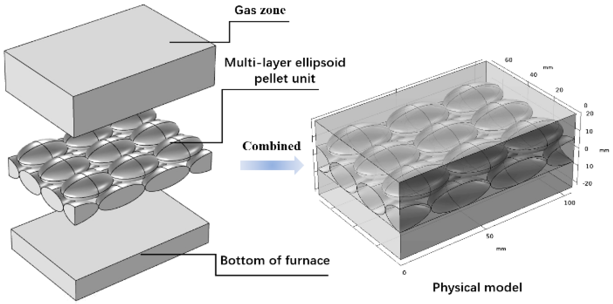
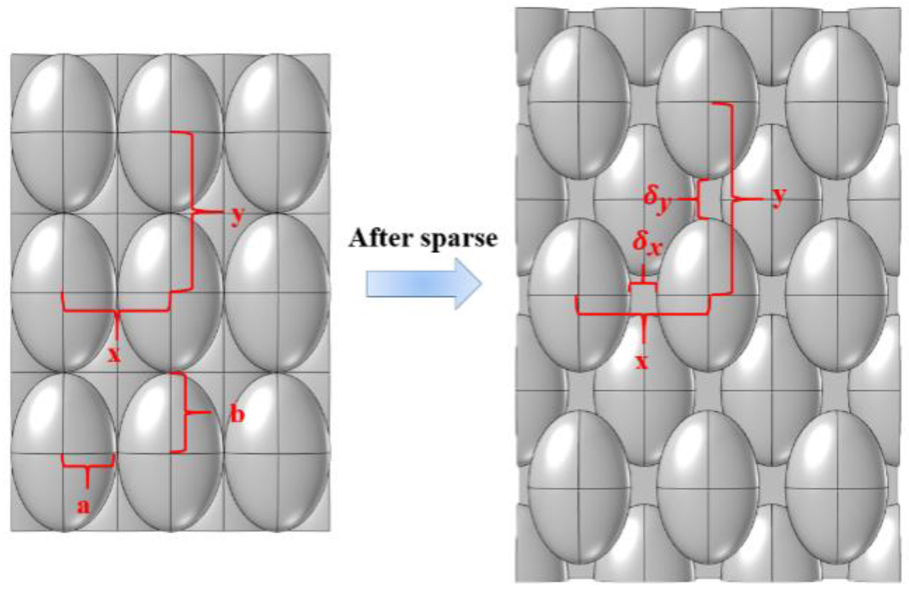
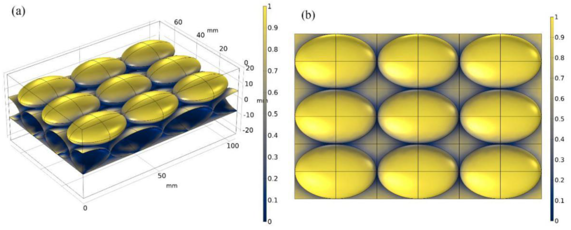
2.1. Physical Model and Assumptions

Based on a more realistic situation, a more stable staggered arrangement of the pellet bed was considered, which is shown in Figure 1. Since the number of pellets in the furnace is huge, and the size of the furnace is much larger than the size of the pellets, it is considered reasonable to extract a multilayer ellipsoid pellet bed unit for calculation [5]. At the same time, to more realistically reflect the heat transfer and reduction process of a multilayer pellet bed inside the furnace, a gas layer around the pellet bed and the bottom of the furnace was considered. In the model, heat conduction in the gas field, at the bottom of the furnace and their participation in radiation were also considered.
Through the calculation of the chemical model, the reaction heat source and mass source can be obtained, which affects the calculation of the bed temperature and substances, respectively. Though the calculation of the mass transfer model, the concentration of each substance and the overall porosity of the bed can be updated, and results can affect the calculation of the chemical model and temperature, respectively. The specific coupling relationship of Radiation–Heat–Matter–Chemistry (RHMC) is shown in Figure 2.
The following assumptions were adopted in the multilayer ellipsoid pellet bed model.
(1)
During the reduction process, the volume and shape of the pellet bed remain unchanged, and only the porosity variation is considered.
(2)
The pellets used in the bed are of a porous structure. The gas and solid at the same pellet position are in a local thermal equilibrium state [16].
(3)
The pressure inside the pellet is constant, ignoring the reoxidation of iron.
(4)
(Initially, the material distribution inside the carbon-containing pellets is even.
(5)
In particular, the gas velocity around the pellet is small, the influence of convective heat transfer is ignored, and only the heat conduction effect of the gas is considered.
(6)
Ignore the radiation absorption by the gas, and the existence of the gas domain does not affect the propagation of the radiation.
(7)
It is assumed that the bottom of the furnace is a flat structure, and the material is sand.
In order to establish the pellets layer model and verify the position and spacing influence of the pellets on heat, mass transfer, and direct reduction process, it was assumed that the initial ellipsoid pellets arrangement is regular and dimensionless parameter ξ was defined to represent the pellets layer offset in the bed. The definition of ξ is shown as follows. The left side in Figure 3 is the case of ξ = 0, and the right side is the case of ξ = 0.5.
ξ = δ x a = δ y b
and so:
δ x = a ξ
δ y = b ξ

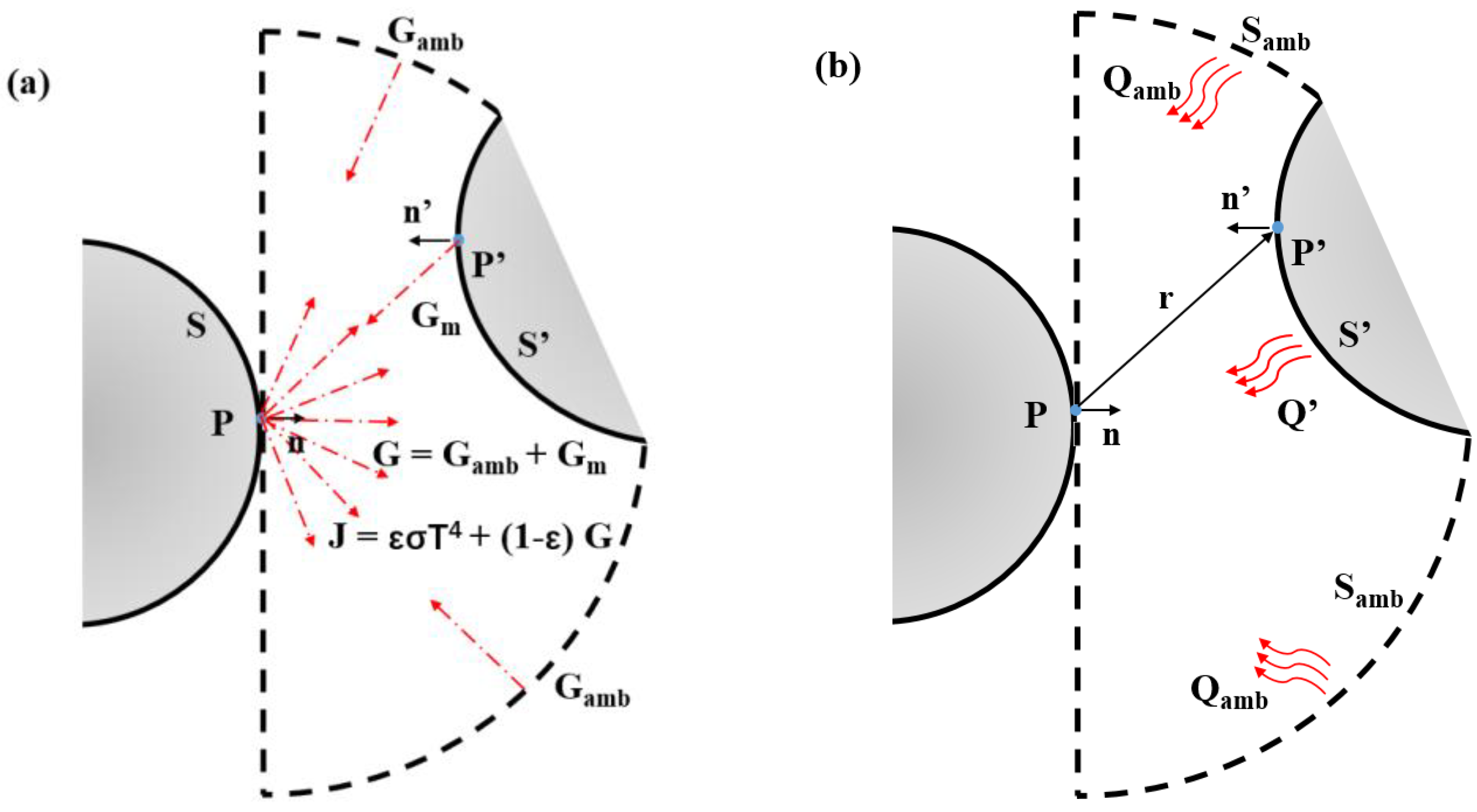
2.2. Surface Radiation Model and Calculation of the View Factor

The two-dimensional pellet was used as an example to discuss the radiation heat transfer process between the pellets in the material layer, as shown in Figure 4. It can be seen from Figure 4a when taking the pellet on the left as the object, the radiation amount of the surface node P can be calculated first to obtain the heat flux of P. By further calculating the radiation process on surface S, heat flux distribution on the left pellet surface can be obtained. To calculate the radiation of the P node, as shown in Figure 4b. It is necessary to calculate the viewing angle factor of each node P’ on the surface S’ of the opposite pellet and the ambient view factor to the P point. This process is more complicated but more accurate than the calculation of the radiant heat exchange network (finding the average value of surface radiation).
As shown in Figure 4a, consider P point has the radiation coefficient ε (the pellet was set as 0.85 [17], and the bottom of the furnace is set to 0.7). The total incoming radiative flux is defined as G. The total outgoing radiative flux called radiosity can be denoted as J. In the calculation of the entire radiation process, the surface radiance is discrete in a linear manner.
J = ( 1 ε ) G + ε σ T 4
G = G a m b + G m
where:
G a m b = F a m b σ T a m b 4
In the equation, Gm is the mutual irradiation, coming from other boundaries in the model. Famb is an ambient view factor. σ is the Stefan–Boltzmann constant (5.6704 × 10⁻⁸ [W/(m2·K4)]). Tamb is the ambient temperature.
Therefore, for the heat flux density q at point P, it can be calculated as:
q = G J = ε ( G σ T 4 )
The strategy for evaluating view factors is important to any radiation simulation. In this way, the radiant heat transfer of the whole process can be calculated by evaluating Famb and Gm. The following surface integral gives the mutual irradiation at point P:
G m = S ( n r ) ( n r ) π | r | 4 J d s
The ambient view factor Famb is determined from the integral of the surrounding surfaces S′, which is denoted as F′.
F a m b = 1 F = 1 S ( n r ) ( n r ) π | r | 4 d s

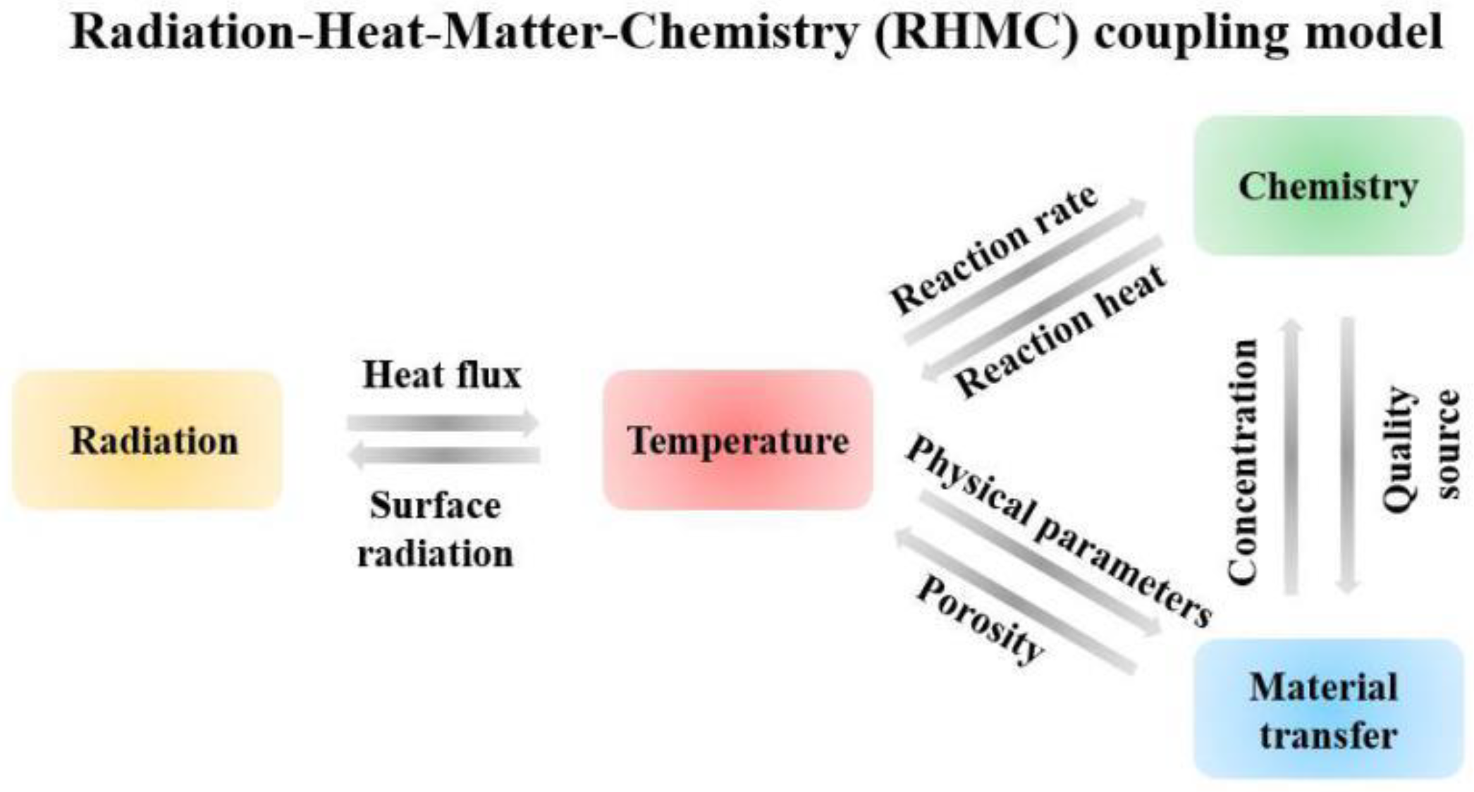
2.3. Establishment of the Heat Transfer Model

During the direct reduction of carbon-containing pellets, heat transfers from the furnace chamber to the pellet surface by thermal radiation. Nevertheless, still, some of the heat is transferred to the surface of the pellet from the gas layer. Therefore, to calculate the heat transfer of the pellets in the rotary hearth furnace more accurately, heat transfer conditions at the bottom of the furnace and the gas area are specifically considered. The specific model is shown as follows. By default, the shape functions used for the temperature in porous media are linear.
Energy conservation equation of ellipsoid pellets [18,19]:
( ρ C p ) e f f T t + q = Q
q = k e f f T
where:
( ρ C p ) e f f = θ p ρ p C p , p + ( 1 θ p ) ρ C p
k e f f = k p θ p k ( 1 θ p )
Q = j R j ( Δ H j )
Δ H j = i p r o d v i j h i i r e a c t v i j h i
In the equation, θp is the volume fractions, θp = 1 − εp, εp is porosity; ρ p is the solid phase density. Cp,p is the solid phase constant pressure heat capacity; kp is the thermal conductivity of the solid phase. ρ is the gas phase density. Cp is the gas phase constant pressure heat capacity. k is the vapor phase thermal conductivity. keff is the effective thermal conductivity, calculated using the power-law equation [18]. Rj and Δ Hj represent the reaction rate and the heat of jth reaction, respectively. vij represents the chemical coefficient belonging to group i (product or reactant) in the jth reaction. hi is expressed as the molar enthalpy of substance i.
It is noted that there is a heat flux density at the surface of the ellipsoidal pellet due to radiation, which conforms to Equation (7).
Energy conservation equation at the gas area and bottom of furnace [20]:
ρ m C p , m T t + q = 0
q = k m T
In the equation, ρm is the density of gas or furnace bottom. Cp,m is the constant pressure heat capacity of the gas or furnace bottom. km is the thermal conductivity of the gas or furnace bottom. Initially, the temperature of the gas area and pellets are the same, but the bottom of the furnace still has a higher temperature.
Since the calculation model is a unit module of a large number of pellets in the furnace, there are symmetric conditions at the edge of heat transfer and thermal insulation conditions at the bottom of the physical model (Figure 1), which are satisfied in the following equation.
n q = 0
There is a convection heat transfer at the top of the calculation model.
- n q = h ( T a m b T )
Since the upper surface can be regarded as the forced convection of the flat type, there are empirical formulas can be adopted [21]:
h = 2 k L 0.3387 Pr 1 / 3 Re 1 / 2 ( 1 + ( 0.0468 Pr ) 2 / 3 ) 1 / 4 if   Re 5 × 10 5 = 2 k L Pr 1 / 3 ( 0.037 Re 4 / 5 871 ) if   Re > 5 × 10 5
where:
Re = ρ L v μ
In this equation, L is the length of the upper surface. ρ, μ, and Pr are the physical parameters of the mainstream gas, and CO is used here as the gas composition. v is the speed at the bottom of the furnace, which is 4 m/s.

2.4. Porous Media Mass Transfer and Chemical Reaction Model

For each ellipsoid pellet in the multilayer pellet bed model, the mass transfer equation is shown as follows. In most mass transport problems, the concentration of substances is generally discretized using a linear method.
ρ i t + J i = R i ω i R i
J i = ( ρ 0 D e , i f k ω i J c , i )
where:
M n = ( i ω i M i ) 1
J c , i = ρ 0 ω i k D k f ω k
D e , i f k = ( 1 D e , i f + 1 D i k ) 1
D e , i f = f e ( ε p , τ F ) D i f
According to the aerodynamic theory:
D i k = λ p a t h 3 8 R T π M i
According to Millington–Quirk model:
f e ( ε p , τ F ) = ε p τ F
τ F = ε p 1 3
In the equation, ρi is the concentration of substance i in a porous medium; ρ0 is the initial density of the mixture; Ri is the reaction source term; ωi is the mass score; D i f is the diffusion coefficient of matter i ; D e , i f is the molecular diffusion coefficient of substance i in a porous medium; D i k is the Knudsen diffusion coefficient of component i in a porous medium; D e , i f k is the effective diffusion coefficient of substance i in a porous medium; Mi is the molar mass of substance i; εp is porosity; τF is the tortuosity factor in porous media; λpath is the mean free path.
The transport of substances in the pellets will be affected by the reaction and temperature, and the variations in concentration will be fed back to the progress of the reaction and the change in pellet porosity, thus affecting the pellets’ bed temperature.
At the edge of an ellipsoid pellet, the material transport equation is shown as:
n J = h m ( ρ g , k , ρ k )
where ρg,k,∞ is the concentration of component k in the mainstream; ρk is the concentration of substance k on the pellet surface; hm is the surface convection mass transfer coefficient, which is calculated by the classical Ranz–Marshall correlation [14].
S h = D h m D e , i f k = 2.0 + 0.6 Re 0.5 S c 1 / 3
Re = ρ D v μ
S c = μ ρ D e , i f k
In the above equation, v is the surface gas velocity; D is the equivalent pellet diameter; μ is the aerodynamic viscosity.
There is a large number of ellipsoidal pellets in the rotary hearth furnace, and the model calculated is just a unit structure of the pellet bed. Therefore, it can be considered that the edges of the multilayer ellipsoidal pellet unit (the cut surface of the incomplete ellipsoid at the model edge in Figure 1, the position where the ellipsoid coincides with the entire model boundary side) are the symmetry planes of these ellipsoids. Therefore, at this symmetry plane, it has the following equation:
n J i = 0
In the mass transfer equation, the source of substances comes from the progress of chemical reactions. At present, the direct reduction mechanism of carbon-containing pellets is mainly regarded as a two-step reduction mechanism. It is believed that the solid–solid direct reduction reaction of metal oxides with carbon particles only performs in initiating reduction. The pellet reduction mainly depends on the reaction of intermediates CO and CO2. The direct reduction reaction equations of carbon-containing pellets are as follows [22,23].
3 Fe 2 O 3 ( s ) + CO ( g ) 2 Fe 3 O 4 ( s ) + CO 2 ( g )
F e 3 O 4 ( s ) + 4 C O ( g ) 3 F e ( s ) + 4 C O 2 ( g )   ( T < 570 ° C )
F e 3 O 4 ( s ) + C O ( g ) 3 F e O ( s ) + C O 2 ( g )   ( T 570 ° C )
F e O ( s ) + C O ( g ) F e ( s ) + C O 2 ( g )
Z n O ( s ) + C O ( g ) Z n ( g ) + C O 2 ( g )
C O 2 ( g ) + C ( s ) 2 C O ( g )
The direct reduction reaction mechanism of carbon-containing pellets is very complicated. Here, the Arrhenius formula was used to describe the kinetic model of the reaction. For each chemical reaction, the reaction rate is:
r j = k j f i r e a c t c i
where:
k j f = A f ( T T r e f ) n f exp ( E f R g T ) ,   T r e f = 1 K ,   n f = 1
In the equation, ci is the molar concentration of substance i with a unit of mol·m−3.
The progress of the chemical reaction is affected by furnace temperature, but the calculated reaction heat acts on the temperature calculation. Besides, the interaction between variables is described in Figure 2, which will help the establishment of the entire model.

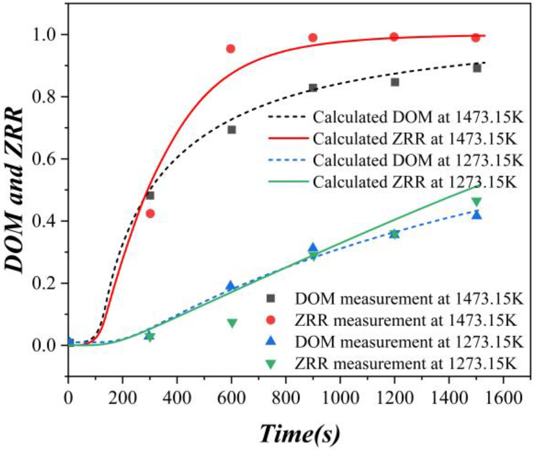
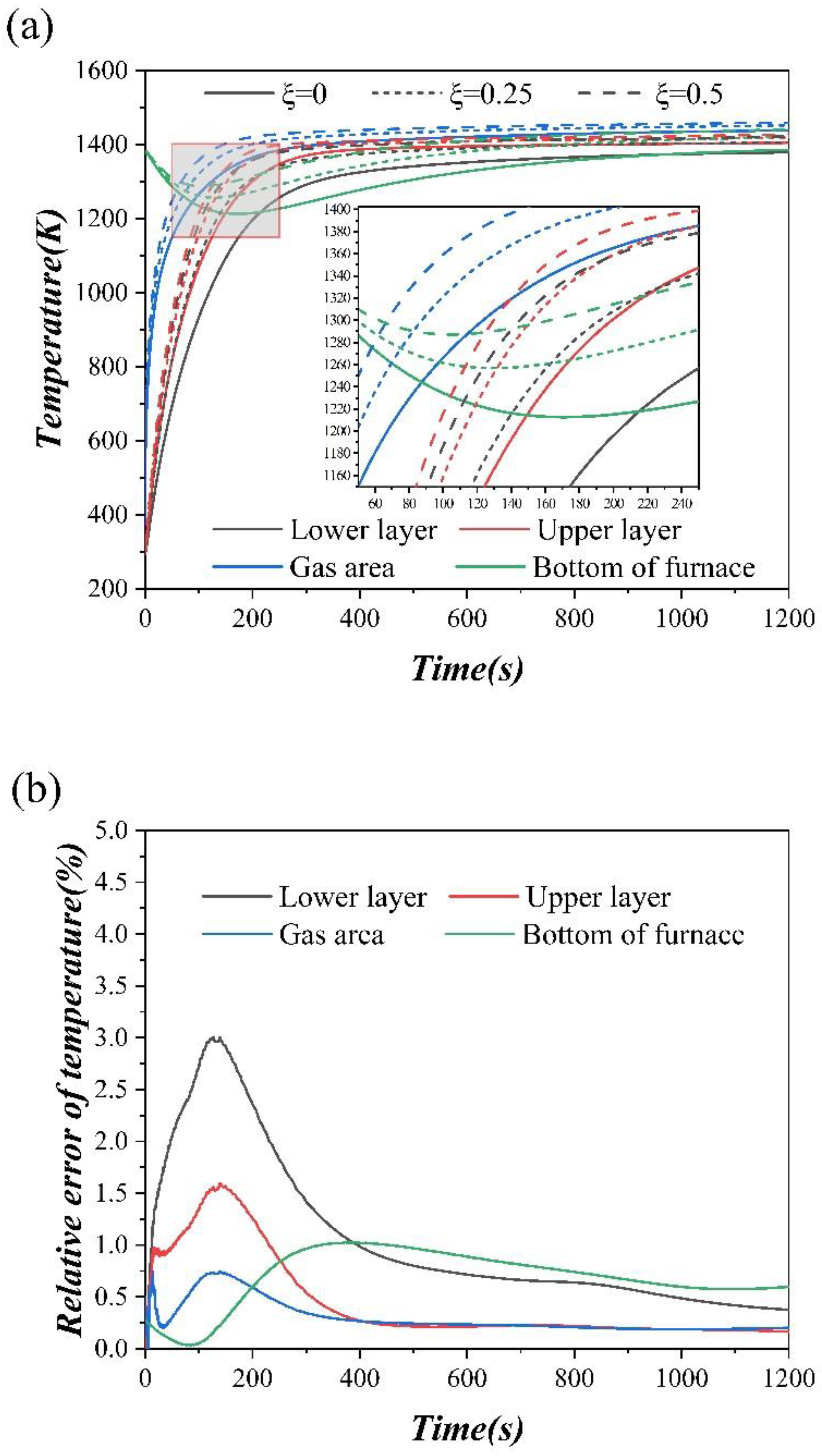
2.5. Physical Properties Calculation and Model Evaluation

The following is the calculation of the physical parameters of the internal components (gas phase or solid phase) of the pellet. The density of a gas or solid phase is calculated as:
ρ r = 1 i ω i ρ i
Constant pressure specific heat capacity of gas or solid phase:
C r , p = ω i C p , i M i
Gas or solid thermal conductivity of pellets:
k r = 0.5 [ i x i k i + ( i x i k i ) 1 ]
x i = c i i c i
The value of i is represented as a gas phase or solid phase.
For the complete pellet, the apparent density is defined as:
ρ a = ε p ρ + ( 1 ε p ) ρ p
The porosity is derived from the conservation of mass as:
ρ a , 0 ( w c , 0 + w F e 2 O 3 , 0 i F e 2 O 3 + w F e 3 O 4 , 0 i F e 3 O 4 + w F e O , 0 i F e O + w z n o , 0 1 ) = ρ a ( w c + w F e 2 O 3 i F e 2 O 3 + w F e 3 O 4 i F e 3 O 4 + w F e O i F e O + w z n o 1 )
ε p = C 0 A ρ s ρ g ρ s
where:
C 0 = ρ a , 0 A 0
A = ( w c + w F e 2 O 3 i F e 2 O 3 + w F e 3 O 4 i F e 3 O 4 + w F e O i F e O + w z n o 1 )
i F e 2 O 3 = 16 × 3 16 × 3 + 56 × 2
i F e 3 O 4 = 16 × 4 16 × 4 + 56 × 3
i F e O = 16 16 + 56
In the equation, ρa,0 represents the initial value of ρa, and other letters are similar. ρp is the density of the solid phase, and ρg is the density of the gas phase.
Degree of metallization (DOM) and zinc removal rate (ZRR) are as follows:
DOM = F e M F e T × 100 %
ZRR = Z n i Z n f Z n i × 100 %
where FeM and FeT are the mass of metallic iron and total iron after reduction, respectively. Zni and Znf are the zinc content of the pellets before and after reduction, respectively.
A single spherical pellet model verified the reduction reaction kinetics, and the calculated values of DOM and ZRR were compared with that of the experimental values in the literature [23]. The comparison result is shown in Figure 5. Through comparison, it is found that the calculated DOM and ZRR values of the kinetic reaction model are in good agreement with the experimental values, which shows the mechanism and kinetic model of the reduction process are correct. Then, the single pellet direct reduction model can be used for the reduction model of the material layer in the rotary hearth furnace.

3. Results and Discussion

The main initial pellet composition is shown in Table 1 below. The total mass fraction of the iron element in the pellet is 39.76%. The primary initial component constitutes about 91% of the pellet. The others are considered as inert elements that do not participate in the reduction process.
In order to obtain the parameters in the pellet bed at the key positions, letter symbols were used for description, as shown in Table 2.

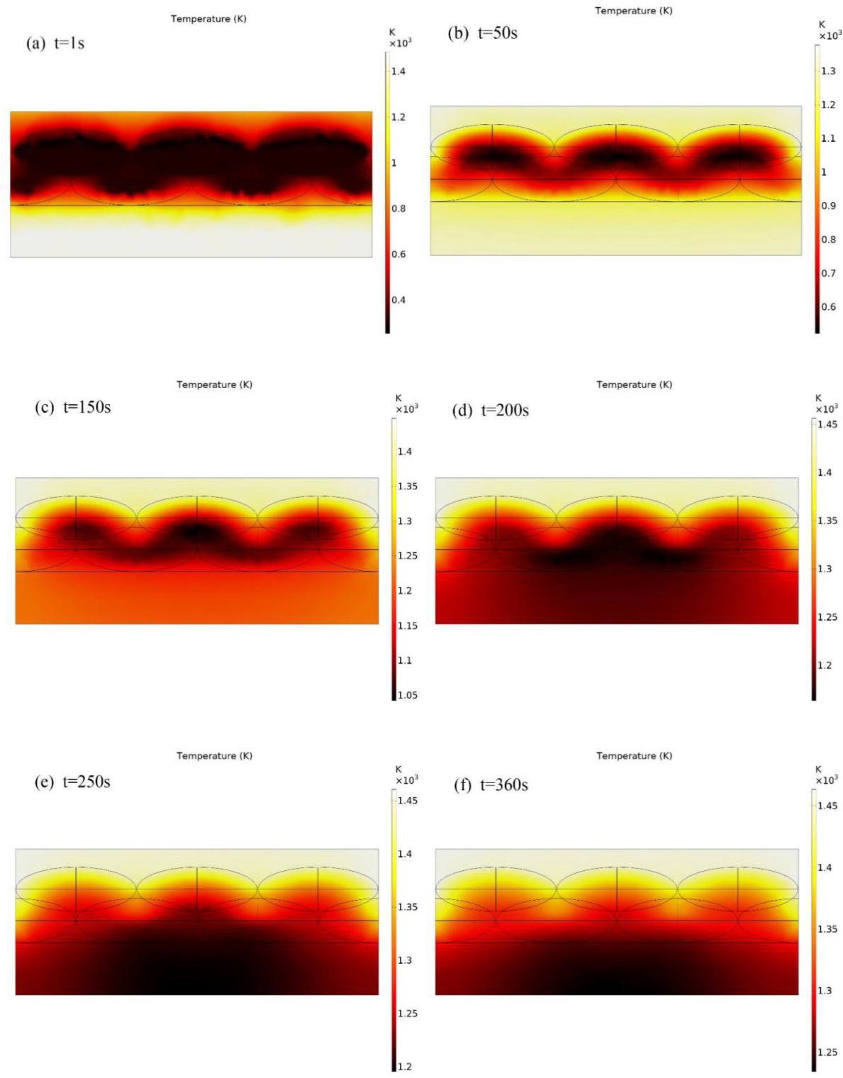
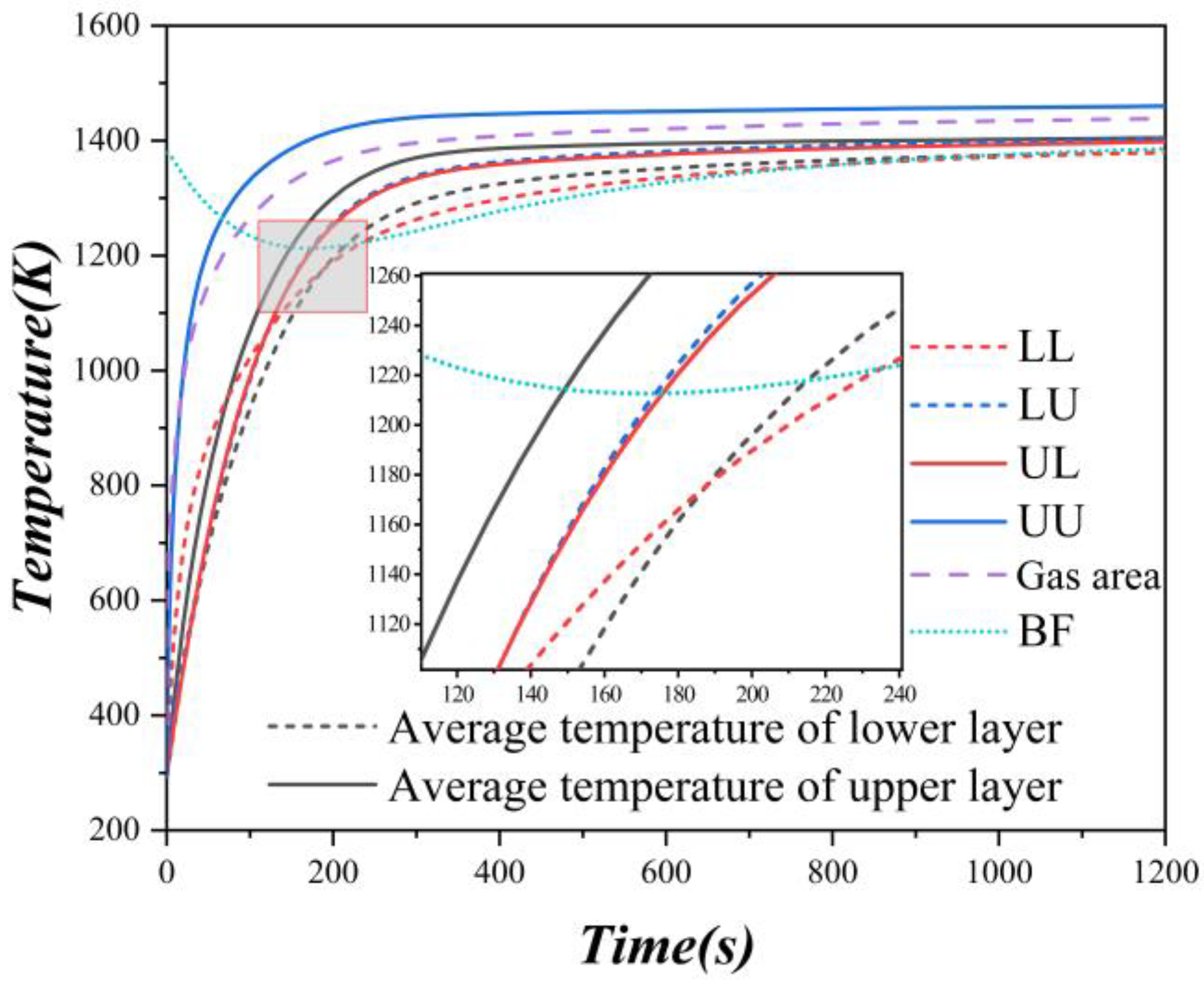
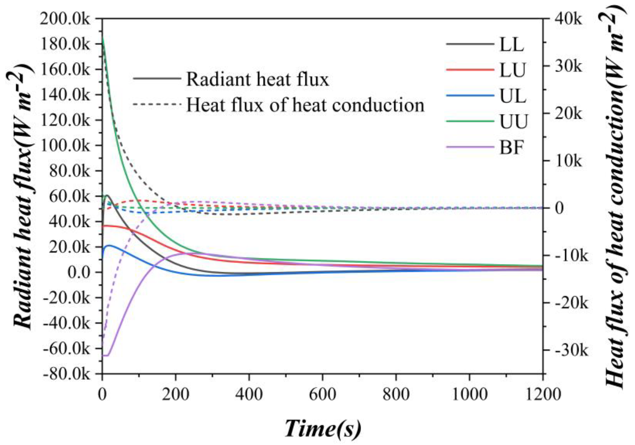
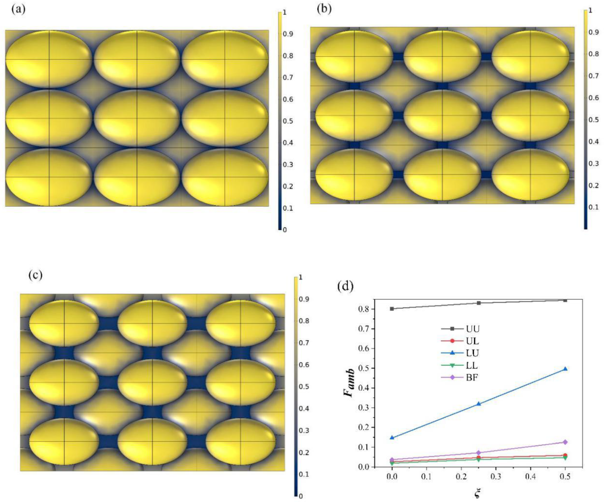
3.1. Radiative Heat Transfer Process of Ellipsoid Pellet Bed

The distribution of the ambient view factor Famb on the surface of the material layer is shown in Figure 6. Because of the cover by other pellets, the corners and the lower pellets surface have a smaller Famb, which will result in receiving less heat from the furnace. In the figure, the bright yellow areas are on the upper pellet, and their Famb value is larger. The value of the lower pellet Famb is smaller. Famb affects the direct radiation degree from the furnace. The difference in Famb value was due to the positional relationship, which will inevitably lead to a difference in heat transfer, and then lead to a more complete reduction process of the upper layer pellets. However, the lower layer pellets reduction degree is poor.
The temperature distribution of the multilayer pellet bed is shown in Figure 7, which is the case when t = 1, 50, 150, 200, 250, and 360 s, respectively. The cross-section temperature of the multilayer pellet bed at the middle position was specifically presented in Figure 6b. It can be seen that the initial temperature of the pellet bed and the gas field is lower, and the bottom of the furnace has a higher temperature. As the reduction progresses, the temperature of the upper bed gas area gradually increases, and its temperature rise is mainly due to the convection heat exchange of the furnace. The surface of the upper pellets in the bed also rises faster, because the larger Famb makes it more irradiated by the furnace. The bottom of the furnace mainly transfers heat to the lower surface of the lower pellets in the form of heat conduction and radiation, providing a preliminary temperature rise. The upper pellets and the lower pellets exchange heat in a radiant and thermally conductive manner. Later, when the temperature of the upper pellet reaches a higher value, the overall heat transfer process is gradually spreading downward from the upper layer. The temperature at the bottom of the furnace will gradually increase after the initial decrease. In this process, preliminary heating of the lower pellets at the bottom of the furnace is very important, which ensures that lower pellets DOM and ZRR have high values at reduction end.
The temperature variations at different bed positions are shown in Figure 8. Since the temperature of the entire gas area shown in the figure is an average value, it starts to rise more slowly than the upper surface of the upper pellets. However, the temperature of the gas near the upper surface of the upper pellet is higher. After going through a falling process, the average temperature at the furnace bottom gradually rises again at about 200 s and returns to the initial temperature value after the 1200 s. The phenomenon indicates that the furnace bottom can heat the lower pellets stably during initial reduction. Figure 8 also shows that the average temperature of the upper pellets’ is much higher than that of the lower, and the temperature difference between the upper surface of the upper layer and the upper surface of the lower layer is obvious. In the initial reduction stage, the temperature rising rate of the lower pellets lower surface is second only to the upper pellets’ upper surface, which is mainly due to the bottom furnace contribution. The temperatures of the lower layer upper surface and that of the upper layer lower surface in the bed are not much different, with the lower layer upper surface being slightly higher. The main reason is that the distance between the two pellet layers at this position is small, resulting in about local heat balance. Since the lower layer upper surface is subject to higher furnace radiation, its temperature is also slightly higher.
The radiant and heat conduction heat fluxes variations are shown in Figure 9. It can be seen that only the heat conduction heat flux of the lower layer lower surface and the furnace bottom is larger at the beginning. In comparison, heat flux by conduction at other positions is smaller than the radiant heat flux. The heat flux by conduction at furnace bottom and lower layer pellets lower surface is larger because the temperature difference between them is larger at the beginning since they are next to each other, heat conduction also accounts for a large proportion of the total heat flux. Nevertheless, the variations of the two heat fluxes at the furnace bottom show that the temperature rise around 200 s is mainly due to radiation, and heat conduction becomes less important afterward. It can be judged by the positive heat flux of the upper layer pellets’ upper surface that upper gas region temperature is higher than that of the upper layer pellets’ upper surface. Additionally, results show that the heat from the furnace is received by the upper pellets (the Famb is larger), and then the heat is distributed through the mutual radiation between the pellets.

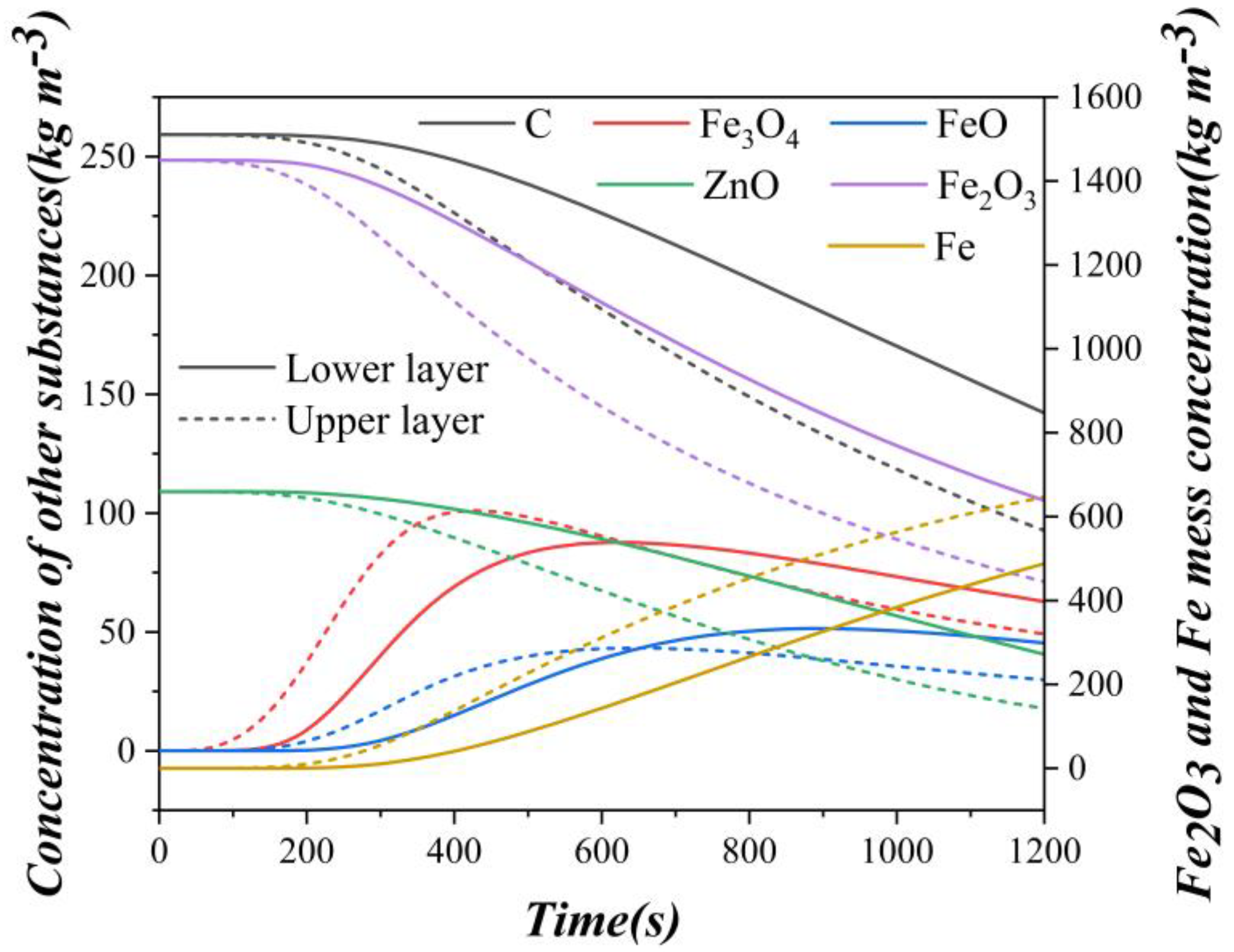
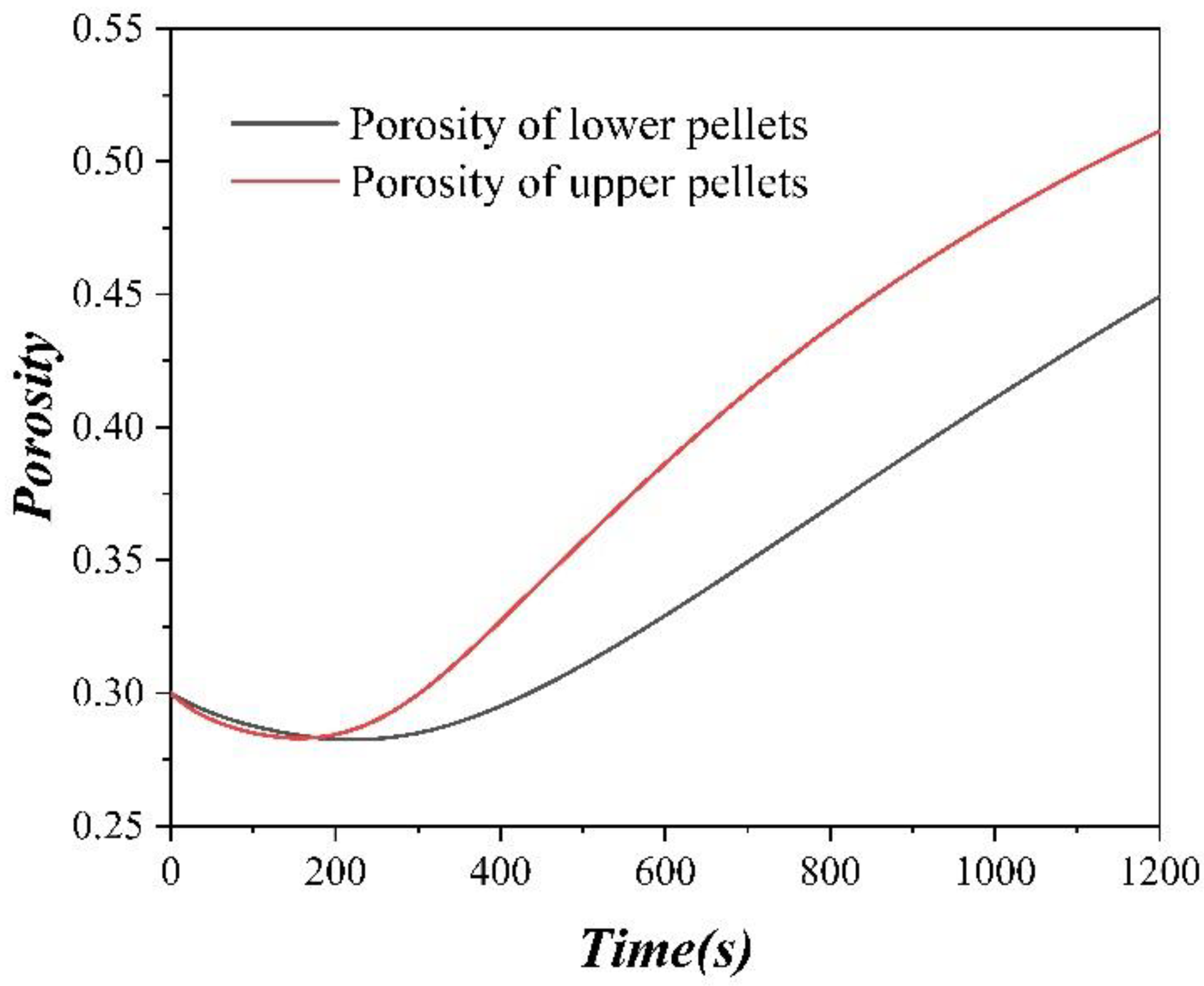
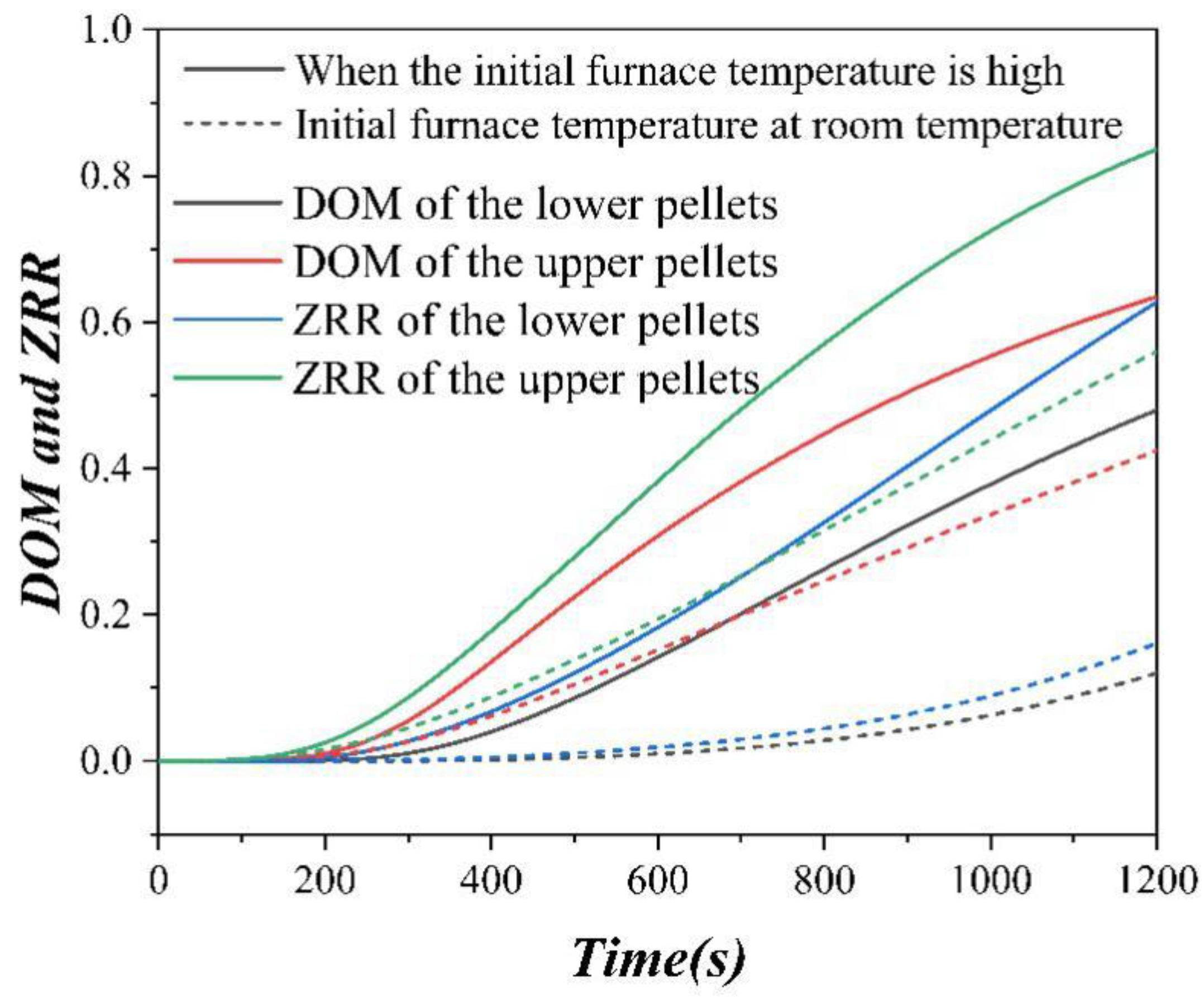
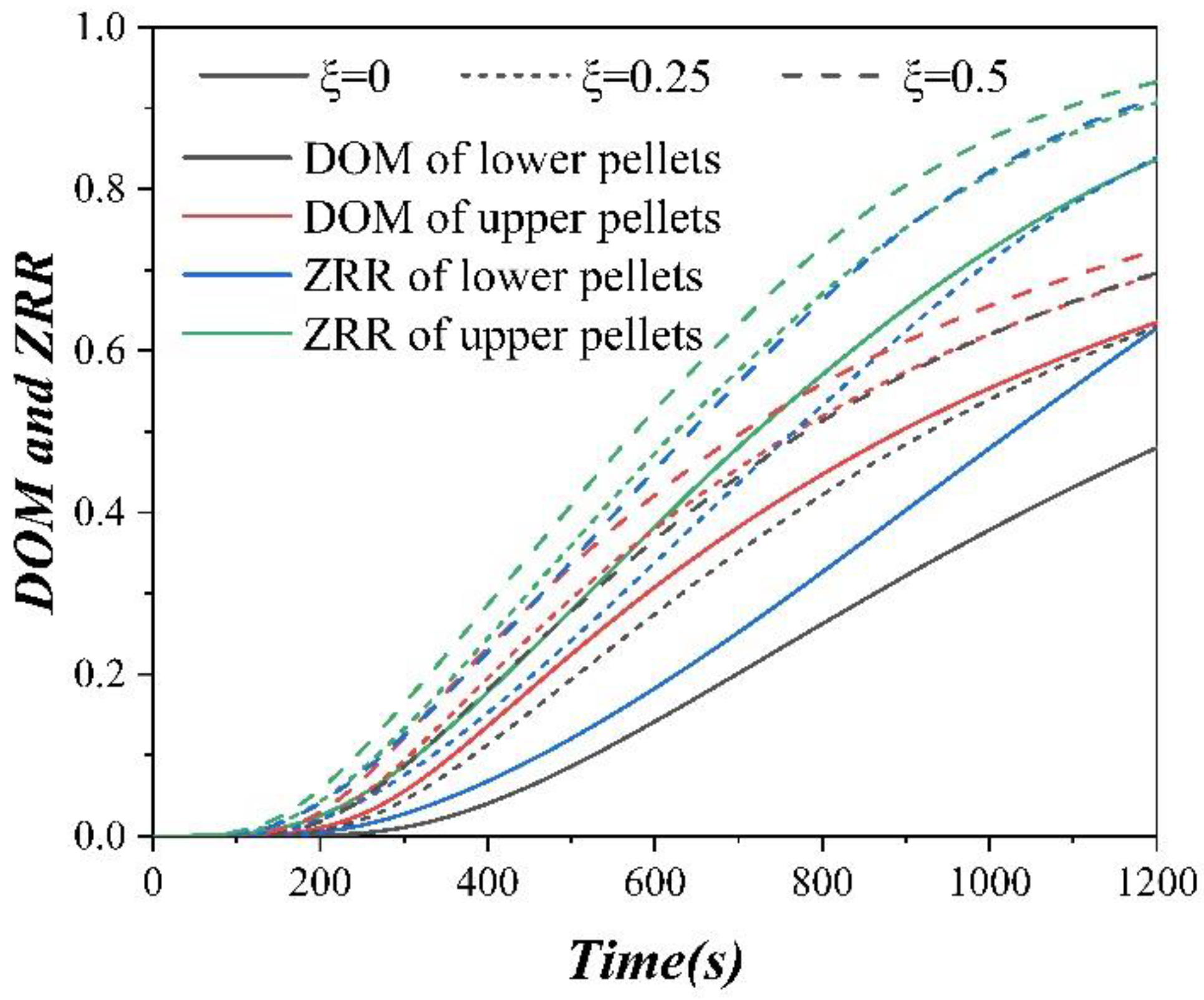
3.2. The Reduction Process of Ellipsoid Pellets in Multilayer Bed

When ξ = 0, the variations of pellet bed substances mass concentration were obtained, as shown in Figure 10. It can be found that the substance concentration changes in the upper pellets are sooner than the lower pellets by a period, indicating that the direct reduction process of the upper pellets is much ahead of the lower pellets. This also results in an uneven distribution of DOM and ZRR in the multilayer bed at the end of the reduction. The reason for this nonuniformity is due to the difference in temperature caused by different heat flux at different locations in the pellet bed layer.
The variation of pellets porosity in the layer with reduction time is shown in Figure 11. Regardless of whether upper pellets or lower pellets in the bed, their porosity undergoes a process of decreasing firstly and then increasing. This is actually since Fe3O4 with a lower density is initially produced in large quantities. In comparison, Fe element with a higher density is produced less, and the gases such as CO and CO2 produced by reduction initially overflow less. The porosity of the upper pellets basically drops to the minimum at about reduction time of 100–200 s, and it is also shown in Figure 10 that elements of C, Fe, etc., did not change much in the upper pellets, but Fe3O4 increased significantly.
The variations of DOM and ZRR of the upper and lower pellets in the multilayer ellipsoid bed are shown in Figure 12. It can be seen that upper pellet DOM and ZRR are higher overall, and the value of ZRR is larger than that of DOM. Through the previous analysis, it is known that this large difference is mainly due to the difference in heat transfer. The furnace continuously heats the upper pellet, and its temperature rises rapidly, both DOM and ZRR are larger. However, in the beginning, only the furnace bottom contributes greatly to the lower pellets heating, then the furnace bottom temperature also decreases greatly when the pellets are heated up. After reduction, there is still a big gap in DOM and ZRR values between upper pellets. It can be found that when the furnace bottom temperature is not higher than the pellets, the reduction degree of the upper and lower pellets will be affected, and the influence of the lower layer is higher. Therefore, to improve the DOM and ZRR of the pellets, the sparse arrangement of the pellets is needed, in which condition that the furnace bottom can obtain the furnace radiant heat and the heat will be used to heat the bottom pellets. A material with a large effective volumetric heat capacity ρCp and a large thermal conductivity k can also be used as the bottom of the furnace. Besides, the furnace can be improved, and directly heating the furnace bottom through other means can also make the lower pellet heat up faster and achieve the purpose of a higher reduction degree.

3.3. Effect of Offset ξ on the Reduction

The offset ξ of the ellipsoid pellets in the material layer bed affects the direct reduction of the pellets. Increasing ξ is essentially sparsely arranging the pellets so that there is more area in the multilayer ellipsoid bed to receive high-temperature radiation from the furnace. Moreover, a certain amount of radiant heat can be obtained at the furnace bottom, and then the heat is transferred to the bottom pellets through the radiation between the surfaces. After changing the position offset ξ, the distribution of the ambient view factor Famb on the surface of the multilayer ellipsoid bed, and the variation of the average value are shown in Figure 13. The most natural variation is that the ambient view factor Famb of the lower pellet upper surface has increased significantly; The radiated area has increased.
Moreover, when ξ > 0, there is a gap that enables the furnace bottom, receiving radiant heat. Figure 13d also clearly shows that Famb of the lower pellet upper surface increases the most, Famb of the upper pellet upper surface and the furnace bottom also increases significantly. Famb of the upper pellet lower surface and lower pellet lower surface also increased, but the increment is not obvious. The change of Famb with pellet offset ξ can be expressed in a linear relationship.
The difference in Famb mainly affects the temperature variation. In Figure 14a, the average temperature variations of the key positions in the pellet bed under different offsets ξ with time were presented. The greater the positional deviation ξ, the greater the minimum value of the average temperature at the furnace bottom, and the greater the average temperature of the gas field, upper pellets, and lower pellets. This is consistent with the previous analysis of the ambient view factor Famb. It can also be found that the variation in temperature is larger when ξ changes from 0 to 0.25 than that when it changes from 0.25 to 0.5, but the difference is not obvious. At this time, for the multilayer ellipsoid bed model, the ξ = 0.5 condition has reached about the limit of forming two-layer pellets. It means that the sparsely arranged pellets allow more heat to be effectively transferred, and the effect on the temperature rise process is linear. The following expression exists.
T ( ξ , t ) = T ( ξ = 0 , t ) + T ( ξ = χ , t ) T ( ξ = 0 , t ) χ ξ
When the function of temperature T(ξ = χ, t) and the function of T(ξ = 0, t) are known, the formula can be used to describe the temperature variation with time at any ξ. Here, the calculated functions of T(ξ = 0.5, t) and T(ξ = 0, t) were used to verify the situation of T(ξ = 0.25, t). The relative error value was shown in Figure 14b. It is found that except for the lower layer pellet, whose maximum error is about 3%, the error of the other three areas is less than 1.5%.
The variations of DOM and ZRR are not linearly related to the change of ξ, but the overall trend is basically that the greater the ξ, the greater the value of DOM and ZRR, as can be seen in Figure 15. This result also shows that the more radiation the pellet is exposed to, the higher degree of its reduction. However, the larger the ξ is, the more sparsely arranged the pellets will eventually lead to a decrease in the overall capacity of the rotary hearth furnace. Therefore, there exists an optimal ξ condition, at which the amount of reduced pellets in the cycle is higher, the final Fe obtained in the furnace outlet is also higher. Finally, its DOM and ZRR values are also higher.

4. Conclusions

In this study, a three-dimensional model coupling radiative heat transfer and direct reduction of the multilayer ellipsoid bed unit in a rotary hearth furnace was established. The model considered the effect of the gas field in the furnace and the bottom region of the furnace on the direct reduction of the multilayer ellipsoidal pellet bed. The environmental viewing angle coefficient in the model was calculated by the finite element method, and the change of the porosity in the pellet during the direct reduction process was also considered. This paper provides a good insight into the direct pellet bed reduction process in a rotary hearth furnace. It is very helpful for the new design of the rotary hearth furnace to obtain a higher pellet reduction degree (for example, why it should maintain a high temperature at the furnace bottom). Additionally, it provides important information on the production process of ellipsoid pellets in RHF. It provides a reference for the emissivity calculation of individual pellets in different positions in the pellet layer. The main conclusions are as follows:
(1) Studies in related literature have shown that the increase of the specific surface area of a single pellet is beneficial to its reduction process [6]. In contrast, the spherical pellet is a geometric shape with the smallest specific surface area. When using ellipsoidal pellets, especially when the total pellet volume keeps constant, the larger the area exposed to the furnace, the higher the reduction degree, although it may bring about a reduction in the total amount of pellets. The ellipsoidal pellets of appropriate size can help increase the metallization rate without a large change in the total pellet amount, which can bring economic benefits to the dust metallurgy industry.
(2) The high temperature at the bottom of the furnace at the initial reduction stage has a great effect on the lower pellets’ reduction, which can increase the DOM and ZRR values of the pellet bed. Moreover, due to the bed characteristic of releasing heat first and absorbing heat afterward by the outside, this effect can be recycled.
(3) During the direct reduction process, the DOM and ZRR of the upper pellets and the reduction process are better than that of the lower pellets. This difference is mainly caused by the heat flux and the temperature difference at different positions in the pellet layer bed.
(4) Famb represents the degree of direct radiation from the furnace. The difference in Famb due to the positional relationship will inevitably lead to a difference in heat transfer. Therefore, increasing the offset ξ has a great effect on improving the Famb of the pellet bed surface at the bed key positions. The function of the offset ξ and temperature is linear. The larger the ξ is, the faster the temperature rising is, and the values of DOM and ZRR have correspondingly improved.

Author Contributions

Conceptualization, N.L., F.W. and L.M.P; methodology, N.L. and F.W.; software, N.L.; validation, N.L. and F.W.; formal analysis, N.L.; investigation, F.W.; resources, F.W.; data curation, N.L.; writing—original draft preparation, N.L. and F.W.; writing—review and editing, F.W.; visualization, N.L.; supervision, F.W.; project administration, F.W. and L.M.P.; funding acquisition, F.W. and L.M.P. All authors have read and agreed to the published version of the manuscript.

Funding

This research was funded by CHONGQING TECHNOLOGY INNOVATION AND APPLICATION DEMONSTRATION PROJECT, grant number CSTC2018JSZX-CYZDX0100.

Acknowledgments

The authors acknowledge the support of professor Liangming Pan on ellipsoid pellet design.

Conflicts of Interest

The authors declare no conflict of interest.

References

  1. Ishikawa, H.; Kopfle, J.; McClelland, J.; Ripke, J. Rotary hearth furnace technologies for iron ore and recycling applications. Arch. Metall. Mater. 2008, 53, 541–545. [Google Scholar]
  2. Wu, Y.L.; Jiang, Z.Y.; Zhang, X.X.; Xue, Q.G.; Miao, Z.; Zhou, Z.; Shen, Y.S. Modeling of Thermochemical Behavior in an Industrial-Scale Rotary Hearth Furnace for Metallurgical Dust Recycling. Metall. Mater. Trans. B 2017, 48, 2403–2418. [Google Scholar] [CrossRef]
  3. Wu, Y.L.; Jiang, Z.Y.; Zhang, X.X.; Xue, Q.G.; Miao, Z.; Zhou, Z.; Shen, Y.S. Process optimization of metallurgical dust recycling by direct reduction in rotary hearth furnace. Powder Technol. 2018, 326, 101–113. [Google Scholar] [CrossRef]
  4. Mishra, S.; Roy, G.G. Reduction Behaviour of Iron Ore-Coal Composite Pellets in Rotary Hearth Furnace (RHF): Effect of Pellet Shape, Size, and Bed Packing Material. Trans. Indian Inst. Met. 2017, 70, 967–978. [Google Scholar] [CrossRef]
  5. Liu, Y.; Su, F.Y.; Wen, Z.; Li, Z.; Yong, H.Q.; Feng, X.H. CFD modeling of flow, temperature, and concentration fields in a pilot-scale rotary hearth furnace. Metall. Mater. Trans. B 2014, 45, 251–261. [Google Scholar] [CrossRef]
  6. Sharma, M.K.; Solanki, V.; Roy, G.G.; Sen, P.K. Study of reduction behaviour of prefabricated iron ore–graphite/coal composite pellets in rotary hearth furnace. Ironmak. Steelmak. 2013, 40, 590–597. [Google Scholar] [CrossRef]
  7. Michishita, H.; Tanaka, H. Prospects for coal-based direct reduction. Kobelco Technol. Rev. 2010, 29, 85–92. [Google Scholar]
  8. Go, H.; Lu, W.K. Using the RHF/SRV or RHF/EAF to produce liquid iron at a low coal rate. Ironmak. Steelmak. 1998, 25, 81–86. [Google Scholar]
  9. Mishra, S.; Roy, G.G. Effect of Amount of Carbon on the Reduction Efficiency of Iron Ore-Coal Composite Pellets in multilayer Bed Rotary Hearth Furnace (RHF). Met. Mater. Trans. B 2016, 47, 2347–2356. [Google Scholar] [CrossRef] [Green Version]
  10. Mishra, S.; Roy, G.G. Effect of CaO on the reduction behaviour of iron ore–coal composite pellets in multilayer bed rotary hearth furnace. Ironmak. Steelmak. 2018, 45, 426–433. [Google Scholar] [CrossRef]
  11. Murao, A.; Sawa, Y.; Hiroha, H.; Matsui, T.; Ishiwata, N.; Higuchi, T.; Takeda, K. Hi-QIP, a new ironmaking process. Iron Steel Technol. 2008, 5, 87–94. [Google Scholar]
  12. Srinivasan, N.S.; Lahiri, A.K. Studies on the reduction of hematite by carbon. MTB 1977, 8, 175–178. [Google Scholar] [CrossRef]
  13. Coetsee, T.; Pistorius, P.C.; De Villiers, E.E. Rate-determining steps for reduction in magnetite-coal pellets. Miner. Eng. 2002, 15, 919–929. [Google Scholar] [CrossRef]
  14. Dasgupta, S.; Saleem, S. A Computational Study on the Reduction Behavior of Iron Ore/Carbon Composite Pellets in Both Single and multilayer Bed Rotary Hearth Furnace. Metall. Mater. Trans. B 2020, 51, 818–826. [Google Scholar] [CrossRef] [Green Version]
  15. Liu, Y.; Zhang, W.; Zhou, Z.; Xu, Y.; Wang, L. Mathematical model of direct reduction in multilayer pellets made of metallurgical dust in a rotary hearth furnace. Heat Transf. Asian Res. 2017, 46, 1443–1459. [Google Scholar] [CrossRef]
  16. Nield, D.A.; Kuznetsov, A.V.; Xiong, M. Effects of local thermal non-equilibrium in steady convective processes in a saturated porous medium: Forced convection in a channel. J. Porous Media 1998, 45, 181–186. [Google Scholar]
  17. Sun, K.; Lu, W.K. Mathematical Modeling of the Kinetics of Carbothermic Reduction of Iron Oxides in Ore-Coal Composite Pellets. Metall. Mater. Trans. B 2009, 40, 91–103. [Google Scholar] [CrossRef]
  18. Nield, D.A.; Bejan, A. Convection in Porous Media, in Convection Heat Transfer, 4th ed.; John Wiley & Sons: Hoboken, NJ, USA, 2013. [Google Scholar]
  19. Bear, J.; Bachmat, Y. Introduction to Modeling of Transport Phenomena in Porous Media; Springer Science & Business Media: Berlin, Germany, 1990. [Google Scholar]
  20. Bird, R.B.; Stewart, W.E.; Lightfoot, E.N. Transport Phenomena, 2nd ed.; John Wiley & Sons: Hoboken, NJ, USA, 2007. [Google Scholar]
  21. Bergman, T.L.; Incropera, F.P.; DeWitt, D.P.; Lavine, A.S. Fundamentals of Heat and Mass Transfer, 6th ed.; John Wiley & Sons: Hoboken, NJ, USA, 2006. [Google Scholar]
  22. An, X.; Wang, J.; She, X.; Xue, Q. Mathematical model of the direct reduction of dust composite pellets containing zinc and iron. Int. J. Miner. Metall. Mater. 2013, 20, 627–635. [Google Scholar] [CrossRef]
  23. Liu, Y. Mathematical model investigation of direct reduction of carbon-containing pellets made of metallurgical dust in a rotary hearth furnace. Ph.D. Thesis, University of Science and Technology Beijing, Beijing, China, 9 April 2015. [Google Scholar]
Figure 1. Multilayer ellipsoid bed physical model. On the left is the specific structure diagram in separation, and on the right is the overall coupled bed physical model.
Metals 10 00994 g001
Figure 2. The coupling of Radiation–Heat–Matter–Chemistry (RHMC) in the bed model.
Metals 10 00994 g002
Figure 3. Top view of the multilayer ellipsoid pellet bed distribution.
Metals 10 00994 g003
Figure 4. Radiation model between surfaces. (a) Incident radiation and outgoing radiation. (b) View factor evaluation between surfaces.
Metals 10 00994 g004
Figure 5. Comparison of the degree of metallization (DOM) and zinc removal rate (ZRR) calculated and experimental results at a reduction temperature of 1273.15 K and 1473.15 K over time.
Metals 10 00994 g005
Figure 6. Distribution of calculated ambient view factor Famb. (a) Three-dimensional (3D) view. (b) Top view.
Metals 10 00994 g006
Figure 7. Temperature gradient variation in the pellet bed middle section at different reduction times. (a) t = 1 s (b) t = 50 s (c) t = 150 s (d) t = 200 s (e) t = 250 s (f) t = 360 s
Metals 10 00994 g007
Figure 8. Temperature variations with reduction time at different bed locations.
Metals 10 00994 g008
Figure 9. Variations of heat flux (radiation and heat conduction) at different bed locations.
Metals 10 00994 g009
Figure 10. Average mass concentration variations of the upper and lower pellets with time.
Metals 10 00994 g010
Figure 11. Variation in the pellet bed.
Metals 10 00994 g011
Figure 12. Variation of DOM and ZRR in the multilayer ellipsoid spherical bed with time.
Metals 10 00994 g012
Figure 13. Effect of offset ξ on the variation of ambient view factor Famb. (a) ξ = 0 (b) ξ = 0.25 (c) ξ = 0.5 (d) The influence curve of ξ on Famb.
Metals 10 00994 g013
Figure 14. Influence of offset ξ on the temperature of the key bed parts. (a) Temperature curve. (b) Error curve.
Metals 10 00994 g014
Figure 15. Influence of offset ξ on the values of DOM and ZRR.
Metals 10 00994 g015
Table 1. Chemical composition of pellets.
CompositionQuality Score (%)
Fe2O356.8
CaO7.94
SiO25.00
Al2O31.68
MgO3.37
TiO20.14
MnO21.01
Zn3.43
C10.16
K2O0.77
Na2O0.41
Table 2. Correspondence between positions and letter symbols in the model.
LocationsLetter Codes
Upper pellet, Upper surfaceUU
Upper pellet, Lower surfaceUL
Lower pellet, Upper surfaceLU
Lower pellet, Lower surfaceLL
Bottom of furnaceBF

