Article

Particle Ejection by Jetting and Related Effects in Impact Welding Processes

1
Institute of Manufacturing Science and Engineering, Technische Universität Dresden, George-Baehr-Str. 3c, 01062 Dresden, Germany
2
Fraunhofer IWS Dresden, Winterbergstr. 28, 01277 Dresden, Germany
3
Institute of Forming Technology and Lightweight Components, TU Dortmund University, Baroper Str. 303, 44227 Dortmund, Germany
4
Institute for Production Engineering and Forming Machines—PtU, The Technical University (TU) of Darmstadt, Otto-Berndt-Straße 2, 64287 Darmstadt, Germany
5
Institute of Materials Science an Engineering, Chemnitz University of Technology, Erfenschlager Straße 73, 09125 Chemnitz, Germany
6
Department for Cutting and Joining Manufacturing Processes, The University of Kassel, Kurt-Wolters-Str. 3, 34125 Kassel, Germany
7
Institute of Materials Science, Technische Universität Dresden, Helmholtzstr. 7, 01069 Dresden, Germany
*
Author to whom correspondence should be addressed.
Metals 2020, 10(8), 1108; https://doi.org/10.3390/met10081108
Submission received: 31 July 2020 / Revised: 13 August 2020 / Accepted: 16 August 2020 / Published: 18 August 2020
(This article belongs to the Special Issue Impact Welding of Materials)

Abstract

:
Collision welding processes are accompanied by the ejection of a metal jet, a cloud of particles (CoP), or both phenomena, respectively. The purpose of this study is to investigate the formation, the characteristics as well as the influence of the CoP on weld formation. Impact welding experiments on three different setups in normal ambient atmosphere and under vacuum-like conditions are performed and monitored using a high-speed camera, accompanied by long-term exposures, recordings of the emission spectrum, and an evaluation of the CoP interaction with witness pins made of different materials. It was found that the CoP formed during the collision of the joining partners is compressed by the closing joining gap and particularly at small collision angles it can reach temperatures sufficient to melt the surfaces to be joined. This effect was proved using a tracer material that is detectable on the witness pins after welding. The formation of the CoP is reduced with increasing yield strength of the material and the escape of the CoP is hindered with increasing surface roughness. Both effects make welding with low-impact velocities difficult, whereas weld formation is facilitated using smooth surfaces and a reduced ambient pressure under vacuum-like conditions. Furthermore, the absence of surrounding air eases the process observation since exothermic oxidation reactions and shock compression of the gas are avoided. This also enables an estimation of the temperature in the joining gap, which was found to be more than 5600 K under normal ambient pressure.

Graphical Abstract

1. Introduction

The use of the ideal material for every single component of a structure can contribute to a reduction of the total mass, a lower consumption of resources, or to cost-saving. This development intensifies the requirement of modern joining technologies to be able to join dissimilar metals with strongly different mechanical, physical, or chemical properties. Many conventional fusion-based welding processes cannot be used for this purpose because of the heat-induced formation of brittle intermetallic phases lowering the weld quality [1].
Collision welding processes such as explosive welding (EXW), magnetic pulse welding (MPW), vaporizing foil actuator welding (VFAW) and laser impact welding (LIW) are based on the oblique collision of metallic surfaces at high velocities [2,3]. They are often described as “cold” solid-state processes since the mechanism for the bond formation is dominated by the prevalent pressure instead of fusion. The creation of intermetallic phases is therefore limited to an uncritical extent. Flat and tubular joints in overlap configuration can be manufactured [4]. In EXW, which was patented in 1962, the required pressure to accelerate one of the joining partners is generated via a controlled detonation [5]. EXW is mainly used for large scale cladding operations [6]. Compared to EXW, MPW processes are easier to control via the electrical charging energy stored in a capacitor bank. The precise energy input allows joining of smaller and thinner parts. So-called welding windows are used to plot the welding result as a function of the collision kinetics [7], characterized by the collision angle β and the impact velocity vimp or axial collision velocity vc at the point of collision, respectively. A crucial influencing factor is the exposure of the joining partner surfaces to the material flow phenomenon, called “jetting”. Jetting is often described as a necessary criterion for the bond formation. There are several approaches to investigate this phenomenon. Some analytical theories describe the material flow due to the fluid-like behavior of the metals in the collision zone during EXW [8]. This assumption is based on the occurrence of high strain rates up to 106 s−1 and high pressures up to several gigapascals at the collision point [9,10]. Different numerical approaches used mesh-less methods to simulate the jetting [10,11,12]. Experimentally, the jet was observed by high-speed imaging [13,14,15] or collected after leaving the gap using so-called witness plates that enabled a quantitative analysis of the composition of the ejected material [16,17,18]. Another imaging method that has been used for the analysis of EXW is pulsed radiography [19]. Comparing the findings of the afore mentioned literature reveals that “jetting” is not necessarily a cumulative stream but can occur as a “cloud of particles”, too. This differentiation was introduced by Deribas et al. [20] and supported by Groche et al. using high-speed imaging and a subsequent investigation of the microstructure [14]. Both phenomena are depicted in Figure 1. The stream can either remain in a cumulative shape or disperse in particles during the further progression of the collision, depending on the collision conditions and involved materials. This is defined as a “jet” [3]. Additionally, brittle oxide layers and other surface contaminations spall from the surfaces due to high strain rates at the point of collision. This “cloud of particles” is the result of the dispersed material stream, the spalled surface layers, or both phenomena. If a cumulative metal stream is formed and sustained during the collision, it might partly be hidden by the cloud of particles [13]. In case of a comparable low energy input, it might even be too small to be visually detectable during the high-speed observation [14].
Taking a closer look at the microstructure at the bond interface of Al3Cu welded by EXW, a thin layer of ultrafine grained (UFG) microstructure has been observed within the newly formed interface, which might be the result of melting and rapid solidification [21]. In contrast, adjacent regions showed strongly elongated grains in welding direction without any macroscopic contraction of flyer and parent. Interestingly, UFG and columnar grown grains, which indicate local melting, were found at the interface for aluminum welds produced by MPW and at comparatively low energies, too [22,23]. In comparison, copper joints with similar weld parameters exhibited an UFG microstructure, but no columnar solidification grains. This indicates that copper did not melt at the collision point and the UFG microstructure was a result of dynamic recrystallization due to the high strain rates at the collision point [23].
A special process model test rig, which operates at relatively low-impact energies, was applied for the determination of the welding window for aluminum and copper. It allowed to differentiate between the macroscopic cloud of particles (CoP), visible in the high-speed images, and a jet in the shape of a metal stream with a thickness of a few microns [14]. Both phenomena were used to describe the boundaries of the welding window in terms of the impact velocity and the collision angle [24]. Bond formation required the metal stream or the CoP to be formed as a result of the plastic deformation of boundary layers close to the colliding surfaces. Due to the high strain rates, oxide layers and contaminations were removed from the surfaces and then ejected. With increasing impact velocity and, thus, induced energy, bonds could also be formed at larger collision angles. The investigation showed that for aluminum and copper, in addition to process-related variables, the yield strength of the material played an important role in the description of this highly dynamic process. Thus, the plastic deformation of the boundary layers had an influence on the formation of joints, even at low energies. In contrast, the lower boundary angle, which was almost constant for different impact velocities, was limited by the possible ejection of the CoP. If the gap was too small and hindered the outflow of the CoP material, it was incorporated into the newly formed interface and prevented bond formation or led to a porous microstructure [25].
Furthermore, the shape of the CoP was determined by fluid dynamic effects depending on the collision angle [14]. For small angles, the CoP appeared as a turbulent flow due to the wall friction at the surfaces of the joining partners. At larger collision angles, flow separations occurred due to boundary layer friction and widening of the joining gap. Therefore, the central flow part moved faster than the ones at the edges. These findings can also be transferred to MPW [15], where the collision angle was identified as a crucial parameter for a thermal surface activation prior to the contact of the surfaces and a successful weld formation [26].
The collision was observed by high-speed imaging and the shape, velocity, and vertical thickness of the CoP were investigated and related to the geometrical bond properties and its strength. A certain velocity of the CoP was required to achieve the targeted geometry and high strength of the bond. At this point it should be mentioned that the increase of the CoP velocity was related to a higher energy induction in the process zone. In contrast, an increased vertical thickness of the CoP reduced the bond strength due to an enhanced formation of intermediate layers, cracks, and voids. It was concluded that a CoP with higher thickness can be trapped more easily in the closing gap and may disturb the bond formation [14,15].
Experiments in a varied gas atmosphere confirmed these results concerning the role of the CoP during bond formation. Pabst and Groche used gases with different densities and found that lower gas densities led to higher CoP velocities and to a successful weld formation even at lower charging energies [27]. This effect became even more apparent in high vacuum where sound welds were achieved already at lower charging energies, probably due to the escape of the ejected particles which was facilitated by the absence of the surrounding medium [28].
Collision welding processes are also accompanied by a bright and characteristic impact flash (“process glare”). Bellmann et al. [29] showed that this impact flash is a necessary, but not a sufficient criterion for the weld formation in ambient atmosphere. The light emission can be a key parameter for an assessment of the temperature conditions in the joining gap [30]. First results indicated that for a few microseconds the local temperatures can exceed the melting temperatures of most metals, which appears to contradict the theory of collision welding as a “cold” process. These findings are supported by Khaustov et al. [31], who identified the shock-compressed gas in the joining gap and the plastic deformation of the joining partners as potential heat sources.
Thus, there are many hints and proofs for very high temperatures before or during the surface contact in collision welding processes. Nevertheless, the influences of certain input parameters on the properties of the CoP are still not completely understood, neither its effect on weld formation. This paper aims for a deeper understanding of collision welding processes and addresses the following questions:
  • How do material properties, surface properties, the collision environment, and the collision kinetics influence the characteristics of the CoP?
  • What is the temperature in the joining gap due to the CoP or compressed air?
  • Is the process glare a multiple superposition of different effects, depending on the process environment?
  • Under which conditions can the process glare be used as a sufficient welding criterion?

2. Materials and Methods

2.1. Nomenclature and Overview
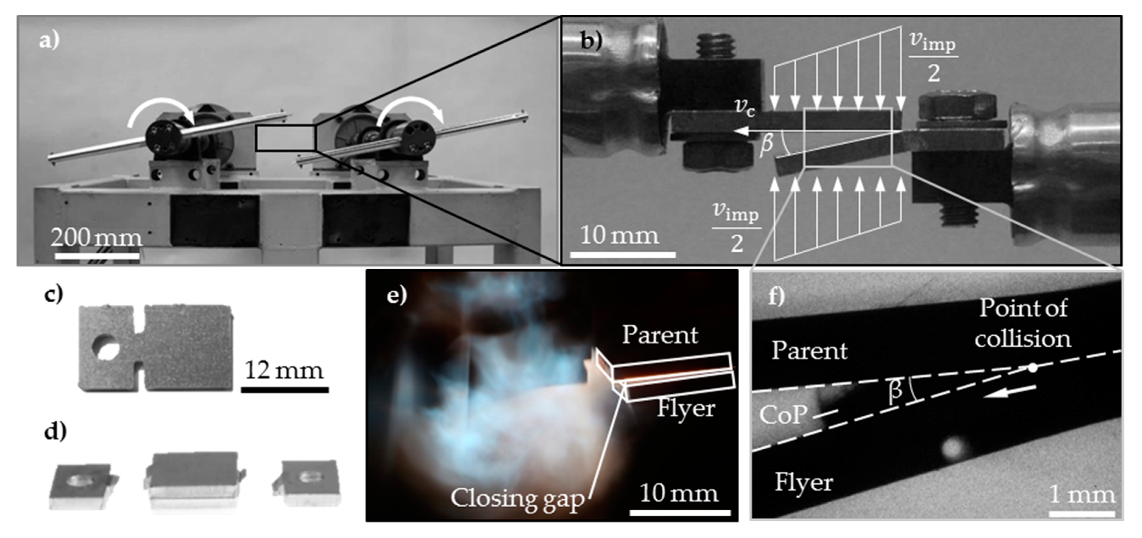
Table 1 lists all symbols that are used within this paper to shorten the captions of figures and tables. The questions mentioned above cannot be answered by a single experiment due to multiple influencing factors. Thus, three different joining setups were used; their specific characteristics are summarized in Table 2. After the welding experiments, the result in terms of weld quality was checked by manual peel testing, as presented by Bellmann et al. [32]. Peel testing of test rig samples was not necessary since non-welded samples were easily identifiable due to the separation of flyer and parent part right after the collision. Some of the welded samples were further prepared for different types of microscopy, see Table 2.

2.2. Test Rig

The first part of the experiments was executed with a special test rig performing the collision process in a purely mechanical approach [33]. The joining partners, two material strips, were mounted at the end of two rotors, see Figure 2a. The rotors rotated in the same turning direction, but started with a phase offset of 45°. When both rotors reached half of the intended impact velocity, the phase offset was eliminated and the joining partners collided with high accuracy and high repeatability in the center between the rotor points, Figure 2b,c. By bending of one joining partner prior to the collision experiment, the oblique collision angle β could be adjusted to a desired value. In the applied configuration the test rig allowed experiments with a maximal absolute impact velocity of 262 m/s; the sheet thickness was kept constant at 2 mm.
Table 2 were taken with a digital single-lens reflex camera (DSLR) Canon 5D with a 100 mm macro lens that was positioned at an angle of approximately 45° to the rotor center axis. The exposure time was set to two seconds, the aperture fixed at F13, and the light sensitivity ISO 100 was applied. An image intensifier camera hsfc pro from PCO working at a dynamic range of 12 bit was used to observe the closing gap between the colliding joining partners [35,36]. Due to the highly dynamic process a short exposure time of 20 ns was necessary. Sufficient lighting was ensured by the laser (CAVILUX Smart by Cavitar, Tampere, Finland) with a wavelength of 640 nm, which was used in a transmitted light configuration. Overexposures of the high-speed images due to the process glare were suppressed by an optical band pass filter.
During the initial experiment the aluminum alloys EN AW-1050 H14 and EN AW-6060 in T4 condition with their chemical composition given in Table 3 served as flyer and parent material, respectively. Both joining surfaces were laser ablated to Ra ~ 0.5 with the laser system CL50 (Nd:YAG laser, 1064 nm wavelength by Clean-Lasersysteme, Herzogenrath, Germany) prior to joining to remove debris. Within this study, the influence of an increased surface roughness of the parent sheet was investigated. The surface topography was generated via laser ablation, too, and exhibited a wavy structure perpendicular to the welding direction with heights of approx. 15 µm (Ra ~ 3.2) and 30 µm (Ra ~ 7.8), see Figure 3.
In the next step, the parent material’s strength was successively increased by replacing it with oxygen-free high conductivity copper (OFHC-Cu) with a purity of more than 99.99 weight percent in two different conditions: as delivered and ultrafine grained after severe plastic deformation by equal channel angular pressing (ECAP) with average grain sizes of ~176 µm and 1.2 µm and yield strengths of 70 MPa and 520 MPa, respectively [40].

2.3. MPW Process

The second part of the impact welding experiments was performed on two commercial pulse generators. In contrast to the test rig, the acceleration of the flyer part was driven by the magnetic pressure pm between a coil and the electrically conductive flyer workpiece. Higher impact velocities were achievable compared to the test rig, but the adjustment and measurement of the collision conditions was more challenging. The sheet welding setup offered the possibility to execute impact welding experiments under vacuum-like conditions and, thus, suppressed oxidation effects and shock compression of the surrounding air [41]. The process analysis in vacuum via long-term exposures [26] or high-speed camera was simplified due to the lowered intensity of the impact flash. The velocity of the jet or of the CoP, respectively, could be estimated by dividing the progressing distance between two photos by the known time shift. Furthermore, the flash starting time tf,start of the process glare and the emission spectrum of the process glare could be analyzed with the setup depicted in Figure 4 by means of a time-resolved flash measurement and diffraction grating, respectively. This procedure allowed an estimation of the temperature in the joining gap while the material combination EN AW-1050 and EN AW-6060 in T4 temper in the sheet configuration was welded. A constant acceleration gap g of 1.5 mm was chosen, and the charging energy E was varied between 9 and 16 kJ. The flat coil B80/10 by PST products was used in combination with the pulse generator PS48-16 manufactured in 2011 by PST products, resulting in a discharging frequency of approx. 18 kHz.
For a spectral analysis of the process glare at the sheet welding configuration, a simple setup consisting of two polymer optical fibers, the transmission diffraction grating GT50-08 by thorlabs (Newton, MA, USA) (830 lines/mm), and the same DSLR used for the long time exposure shots of the welding process was applied, see Figure 4. The first optical fiber was aligned parallel to the coil wire and monitored a position in the welding gap close to the initial contact point (position 1). The second fiber monitored the outer region of the welding gap, which was not affected by the welding process (position 2). The wavelength and sensitivity calibrations of this setup were done with two known wavelengths (green laser pointer λ = 532 nm, bandpass filter λ = 640 ± 12 nm) and a 60 W incandescent bulb modeled as a blackbody emitter at 2700 K.
The movement of the flyer part was monitored and recorded using Photonic Doppler Velocimetry (PDV). This laser-based technology is capable of measuring velocities up to several kilometers per second [32]. The laser source was a 1 W fiber laser module by Redfern Integrated Optics Inc (Santa Clara, CA, USA). The wavelength of the emitted laser beam was 1550 nm; with this setup part velocities of up to approx. 1200 m/s can be recorded. Two PDV probes were applied, which recorded the movement of the flyer through small holes in the parent part, see Figure 4. For instance, the impact velocity vimp could be determined.
The tube welding setup shown in Figure 5 included witness pins with a diameter of 2 mm close to the joining zone. They were made of different materials (St-steel, W-tungsten, and C-graphite) and vaporized by the CoP. A tracer copper coating was placed on the parent surface, beginning at a distance of five millimeters from the initial collision point. The surfaces of the steel and tungsten pins were investigated after MPW using scanning electron microscopy (JSM-6610LV by Jeol, Tokyo, Japan) and energy dispersive X-ray spectroscopy (X-Max 80 mm2, Model 51-XMX0002 by Oxford instruments, Abingdon, UK). The surface topography of the graphite pins was scanned with a microscope (VHX-5000 and universal zoom lens VH-Z100UR by Keyence, Osaka, Japan) The collision angle between flyer and parent workpiece could be modified via the working length lw, as described in [26]. It is defined as the axial overlap between the flyer part and the concentration zone of the working coil, see Figure 5. The charging energy of the pulse generator MPW 50/25 by Bmax was set to 4.5 kJ and led to a maximum tool coil current of approx. 377 kA at a discharge frequency of approx. 20 kHz. The chemical composition and selected mechanical properties of the flyer material aluminum EN AW-6060 and the parent material steel C45 are also listed in Table 3.

3. Results

3.1. Test Rig

The experiments with the initial material combination of the aluminum alloys EN AW-1050 and EN AW-6060 in T4 temper revealed a welding window for collision angles β between 4.5° and 6.6° at a constant impact velocity vimp of 262 m/s. Increasing the roughness of the parent surface to 15 µm narrowed and shifted the range for successful welds to a collision angle of 9.1°. The amount of ejected material for both roughness conditions within their specific welding windows was similar, see Figure 6c,d, while the intensity of the process glare was reduced, see Figure 6f,g. Furthermore, polished cross sections revealed that the waviness of the joining zone increased and exhibited pockets for the laser structured surface (b) instead of a continuous layer (a) along the interface. A roughness of 30 µm inhibited the CoP formation, the process glare and welding completely at the given impact velocity, see Figure 6e,h, respectively.
Replacing the parent material with the copper alloy Cu-OFHC enabled welding for collision angles between 6.6° and 7.5°, while welding was not achievable in this range with the ultrafine grained copper as parent material. Although the shadows in the joining gap and, thus, the CoP densities seemed to be comparable, the process glare was significantly reduced, see Figure 7

3.2. MPW Process for Sheets

MPW experiments with the same material EN AW-1050 for both the flyer and the parent sheet were performed at ambient pressure first. Due to missing PDV measurements, the non-welded samples processed with 18 kJ charging energy are not listed in Table 4. Nevertheless, they enabled the definition of the lower process boundary at 19 kJ charging energy since welding occurred at this energy level with an impact velocity of 224 m/s. Reducing the ambient pressure in the joining gap to approx. 100 Pa enabled welding even with lower impact velocities of 203 m/s. At this point it should be mentioned that due to the design of the vacuum chamber, the distance between the coil wire and the flyer sheet in the active zone increased during the evacuation process of the vacuum chamber, leading to a reduction of the acceleration distance between the joining partners. This effect was compensated by adjusting the charging energy E in 30 preliminary tests to ensure the targeted level of impact velocity vimp and monitor it via PDV.
The reduced ambient pressure in the joining gap not only decreased the lower process boundary, but also influenced the process glare and the interfacial microstructures. Compared with the experiment in ambient atmosphere at an impact velocity of 243 m/s, the process glare under reduced pressure decreased significantly and appeared in an orange to red color, see Figure 8. In addition, the welded area increased, see Table 5. The interface did not contain a porous layer close to the central gap, which resulted in a smooth transition from the non-welded zone in the middle to the adjacent welded regions in Figure 9.
The combined inverse pole figure (IPF) and Band Contrast/Image Quality (IQ) maps in Figure 9 reveal some interesting differences of the weld interfaces caused by the change in ambient pressure. Most notably, the central gap at 100,000 Pa is wider close to the initial weld compared to the sample welded at 100 Pa ambient pressure. The detail map at 100,000 Pa ambient pressure in (b) reveals a slightly porous layer in the weld interface with many very small grains, although to a smaller extend compared to previous reports [22,25]. In comparison, the initial weld interface produced at 100 Pa ambient pressure in (d) is smoother and without a nano-crystalline interlayer.
The high-speed images reveal a CoP that dispersed in the joining gap and glowed brightly in normal ambient atmosphere. If the ambient pressure was reduced, the appearance of the CoP changed to a dark and tongue-like shape, see Figure 10. In both cases no band pass filter was used. The CoP velocity was estimated by dividing the propagation distance between two time steps. It was approx. 4 to 6 km/s in normal ambient atmosphere and about 10 km/s at reduced ambient pressure.
All optical spectra of the process glare in Figure 11 show a prominent peak at short wavelengths, which can be assigned to the intense characteristic aluminum emission line at approximately 396 nm [42]. Although the overall shape of the spectra is unchanged between the two different positions under reduced ambient pressure, the intensity is increased over the whole spectral range at normal ambient pressure. Due to the limited spectral resolution, it is impossible to distinguish bundles of individual emission lines and the continuous blackbody radiation. However, the different process glare colors in Figure 8 and the shift of the intensity maxima to longer wavelengths in normal ambient pressure from the position close to the initial collision point (Pos. 1) to the end of the joining gap (Pos. 2) allow for two main conclusions:
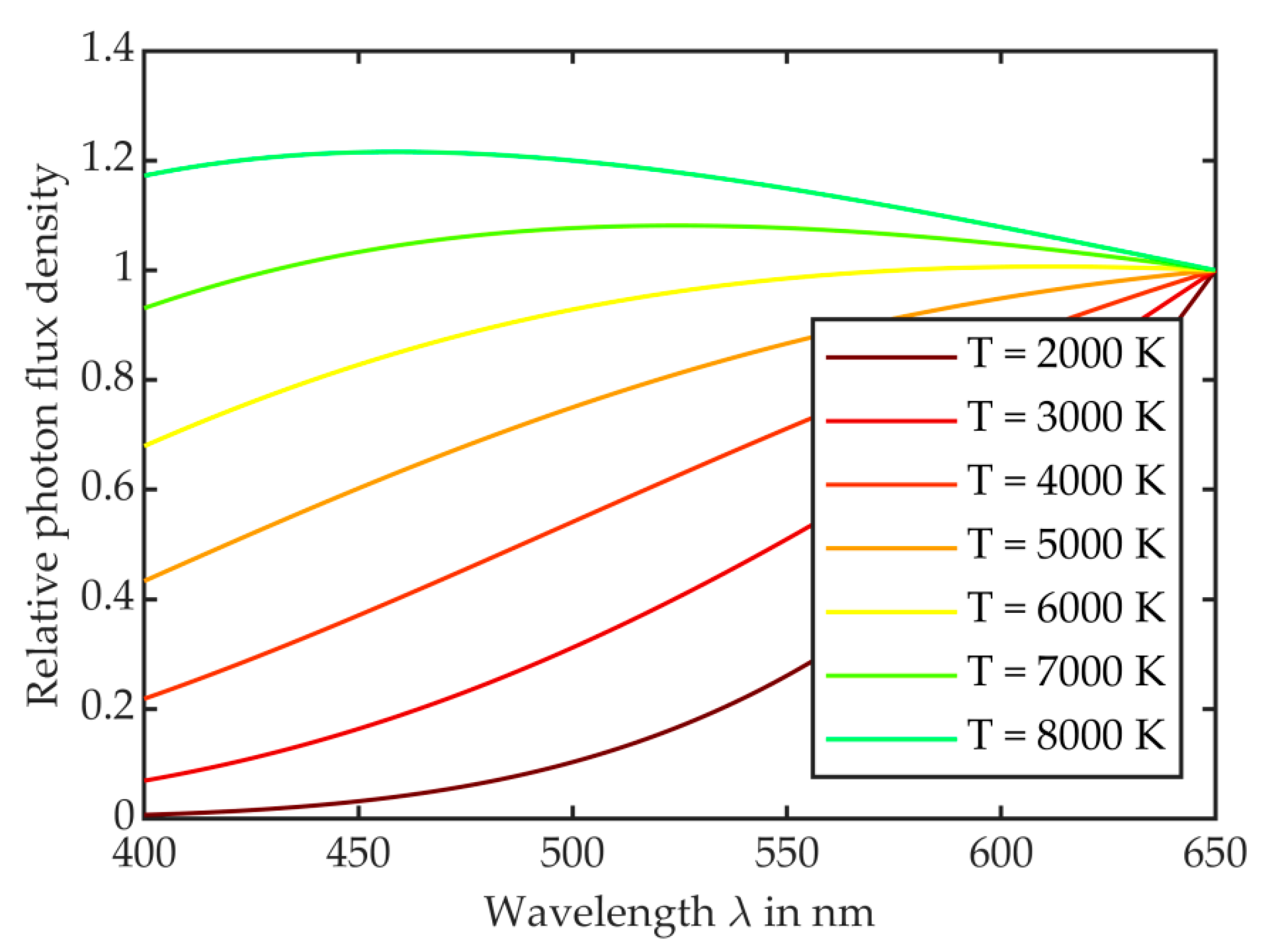
  • The temperature of the light-emitting medium is much higher at normal ambient pressure compared to the reduced pressure conditions.
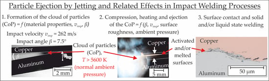
  • At normal ambient pressure, the temperature rises further during the propagation of the collision point. Using Wien’s displacement law (see Appendix A for discussion) and an upper boundary for the photon emission maximum of λ = 650 nm, the temperature of the process glare under normal ambient pressure can be expected to exceed 5600 K.

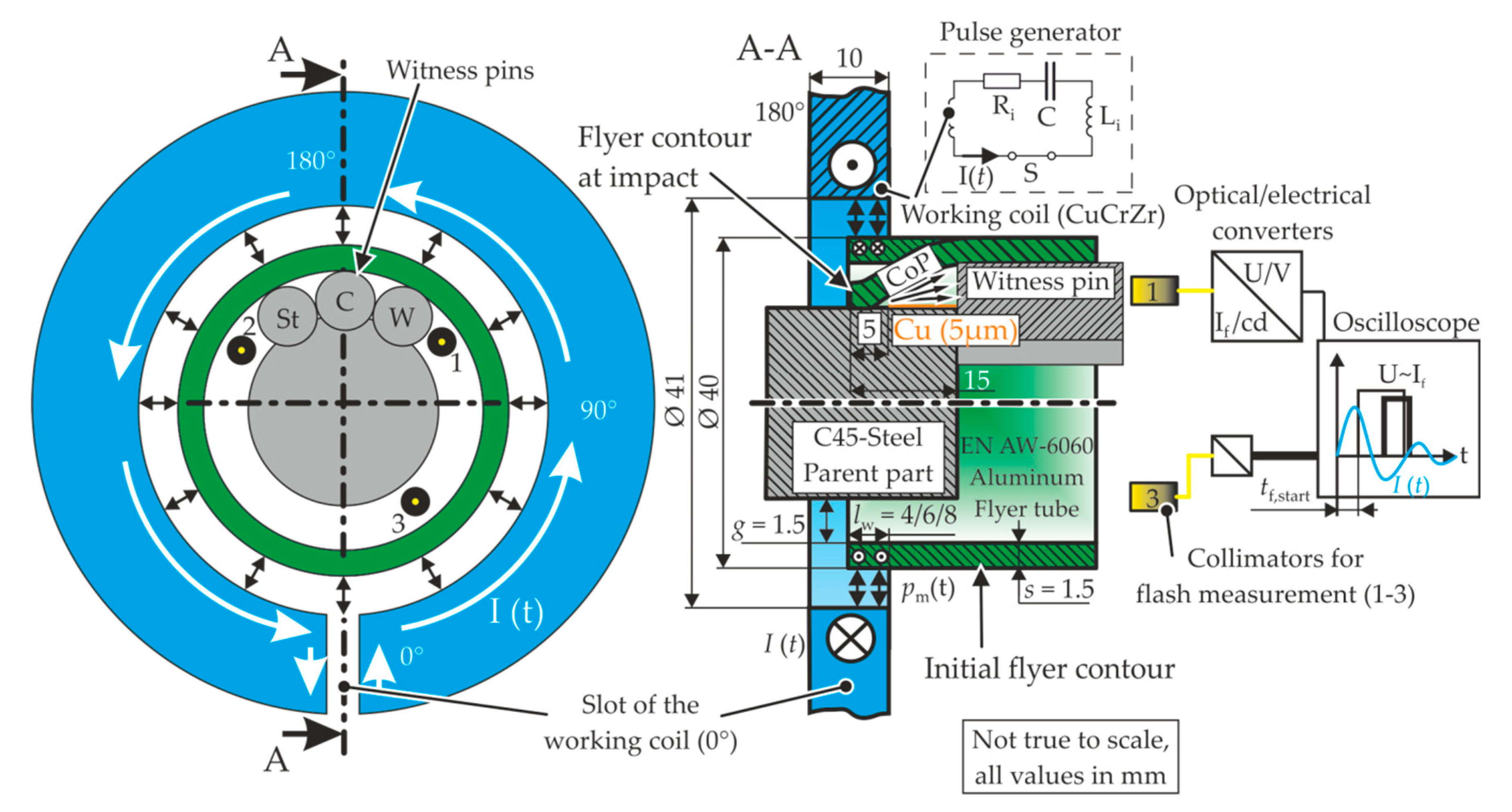
3.3. MPW Process for Tubes

The collision angle during MPW can be controlled by the working length lw [34]. It influences both the appearance of the process glare and the welding result [26]. A working length of 4 mm led to an initial collision angle of approx. 9° where welding was not achievable in the given setup. Increasing the working length to 8 mm decreased the collision angle to approx. 3° and allowed for a weld formation between the aluminum flyer and the steel parent [34]. Moreover, an evaluation of the process glare in the joining gap under vacuum-like conditions revealed a significant temperature increase far above the vaporization temperature of the involved materials. Now, additional MPW experiments were performed at normal ambient pressure to gain deeper insights into the relation between the collision angle and the formation of the CoP as well as its interaction with the witness pins that consisted of three different materials, see Figure 12a. The witness pins were placed side by side at the 180° position of the tool coil. The pin diameter of 2 mm was small compared to the inner circumference of the flyer tube with 116 mm. Thus, the influence of the different radial positions can be neglected. The results are summarized in Table 6. The CoP penetrated into the soft graphite pin, see Figure 12b, while it was deposited on the surfaces of the tungsten and steel pins, as shown in Figure 13 and Figure 14, respectively. In both figures, sections (a) and (b) show the pin surfaces after the cutting procedure before the MPW experiments. Obviously, the deposited layer in (e) and (f) consisted mainly of the aluminum flyer material as well as the dominating iron parent material. Furthermore, the increased oxygen content indicated a partial oxidation of the CoP during MPW.
The collision angle had a big impact on the penetration of the CoP in the graphite witness pin and the structure of the vaporized surfaces on the steel and tungsten witness pins, respectively. For high collision angles the penetration depth in the graphite witness pins was approx. 1 mm, see Figure 12b. There were many single particles deposited on the tungsten pin, leading to a coarse and ragged structure. Energy dispersive X-ray spectroscopy (EDX) revealed no copper, neither on the tungsten pin nor on the steel pin, see Figure 13f and Figure 14f, respectively. In contrast, small collision angles led to a line-shaped penetration area in the graphite pin. Based on the distance of 15 mm to the initial collision point, the angle of ejection could be calculated. It is within a range of 1.9° to 5°, which is in good agreement with the simulated collision angle of 3.4° [34]. At this small angle, a homogeneous aluminum layer with a copper content of ~2 weight percent from the tracer coating and with only a few single aluminum particles was deposited. Compared to large collision angles, the thickness of the layer was lower since the subjacent tungsten was detectable during EDX analysis, too.

4. Discussion

The experimental results presented in this study clearly confirm the hypothesis that high temperatures occur within the joining gap during collision welding processes. The experiments at reduced ambient pressure showed that the temperature increase also takes place in the absence of the surrounding air. Thus, it seems reasonable to relate the temperature increase to the material that is ejected from the process zone. Depending on the collision kinetics and the involved materials, material ejection can either occur as a dense material flow as a jet and/or as a CoP in case of lower impact energies and depending on the collision angle. The thermal energy of the CoP enables and supports all three bonding types that have been reported for collision welding processes so far. Depending on the impact kinetics at the propagating collision point either solid-state bonding, solid–liquid coexistence state bonding, or liquid-state bonding can occur [44]. The influence of the material properties, surface properties, the collision environment, and the collision kinetics on the characteristic features of the CoP were investigated in three different experimental setups, as discussed and listed below:
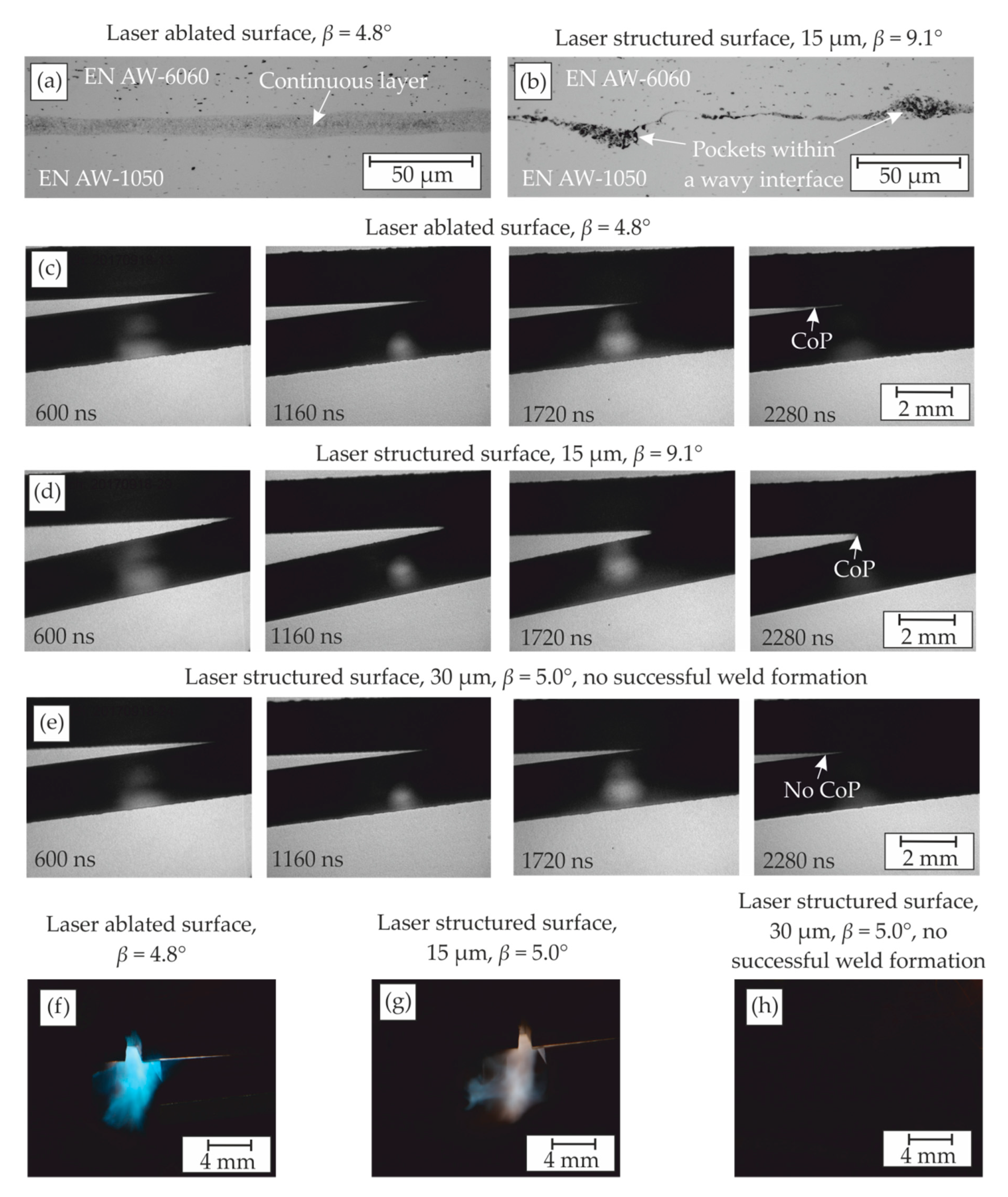
  • Test rig experiments: Decreasing the grain size of the parent material led to an increase in the material’s strength and hindered plastic deformation in the joining zone. This makes it difficult to generate a sufficient CoP for the heating of the surfaces and to form a solid jet that uncovers the base materials.
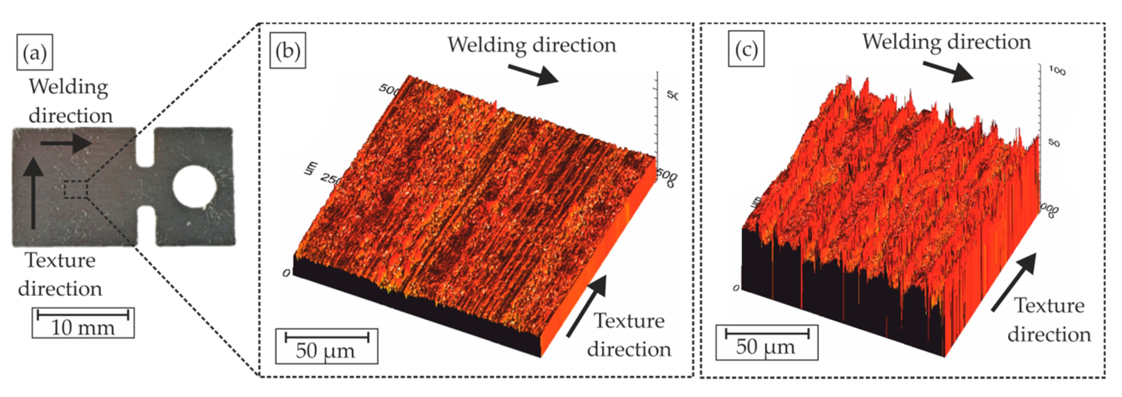
  • Test rig experiments: The escape of the CoP was hindered by an increased surface roughness, which also led to a reduced process glare. The high-speed picture frames as well as the melting pockets in the cross section point to the conclusion that the CoP was partly entrapped in the wavy surface during the movement of the collision point. This effect can be detrimental for the weld formation if the kinetic or thermal energy of the CoP is too high and leads to extensive melting along the interface. Furthermore, it weakens or hinders bond formation due to a lack of direct contact of the activated surfaces of the base material.
  • Sheet welding setup: The surrounding gas lowered the velocity of the escaping CoP, as also reported in [27]. This led to a porous microstructure if the CoP was partially enclosed in the joining zone. In contrast, the microstructure revealed no pores when MPW was performed under vacuum-like conditions, see also [25]. Similar to the observations reported in [28], the necessary impact velocity for a successful weld seam can be reduced in vacuum compared to normal atmosphere. Moreover, the process glare is reduced significantly, either due to the absence of chemical interactions with the surrounding oxygen or because of shock compression of the gas in the joining gap, as described in [45].
  • Tube welding setup: The collision kinetics have a big impact on the characteristics of the CoP. The deep and voluminous craters that are formed by the CoP in soft graphite pins indicated that the kinetic energy of the CoP was higher for larger collision angles, whereas smaller collision angles only led to a single line in the graphite witness pin with significantly reduced depth. The structures of the vaporized surfaces of the witness pins made of steel and tungsten provided insights into the thermal energy of the CoP: Small collision angles led to a higher degree of compression of the CoP in the joining gap and, thus, pronounced heating of the surfaces in the joining zone. The copper tracer that was placed at the end of the actually welded area was detectable on the surface of the witness pins. Since the impact velocity, the plastic deformation, and, thus, the heating due to forming were reduced compared to the initial collision point, the thermal and kinetic energy of the compressed CoP must have been responsible for the melting and transportation of the copper tracer towards the witness pins. The finely dispersed structure of the vaporized pin surfaces supports the hypothesis that the high temperatures in the joining gap resulted from the thermal energy of the CoP. In contrast, compression and heating were reduced for large collision angles, leading to the ragged surface of the witness pins. The surface contained larger aluminum particles and no signs of copper from the tracer surface coating. The chemical composition of the CoP was dominated by approx. 80 weight percent aluminum due to its lower melting temperature and lower strength compared to steel. Consequently, the amount of aluminum that was plastically deformed, melted and finally contributed to the CoP is higher.
One of the key results of the present study is that the temperature in the joining gap at ambient pressure was found to exceed 5600 K. Due to the arrangement of the spectral measurements it can be concluded that this temperature occurred in the rapidly closing welding gap in front of the actual point of collision. This effect can be suppressed at reduced ambient pressure. However, to determine the temperature of the CoP under vacuum-like conditions, a different setup with an increased spectral sensitivity in the infrared range would be needed.
Furthermore, the findings of the present study point to the conclusion that the process glare results from a superposition of multiple, different effects that depend on the process environment:
(a)
In ambient atmosphere, the shock compression of the surrounding air led to a thermal glow. Furthermore, the remarkably high oxygen content on the witness pins provided evidence of an exothermic reaction of the metal vapor with the surrounding oxygen. This reaction contributed to the flash effects, too.
(b)
Under vacuum-like conditions, the intensity of the light emission was reduced, and its appearance depended on the involved materials. In [13], a bright appearance was reported for magnesium (which has a lower boiling temperature than copper), where only a dark metal jet was observed. Thus, it can be concluded that even in the absence of the surrounding air, particles of the involved joining partners with temperatures above the vaporization temperature emitted light and contributed to the process glare. Depending on the local temperatures and pressures, the formation of plasma is also conceivable, but the present study does not provide direct evidence for this phenomenon.
To conclude, it should be noted that the process glare alone cannot be used as a sufficient welding criterion because multiple parameters contribute to the light emission, weld formation, and the corresponding side effects. In a conventional ambient atmosphere, the lightning effect is dominated by the interaction with the surrounding air. Thus, the effect of the collision angle, which significantly influences the welding result, is not directly accessible. Nevertheless, the process glare can be seen as a necessary criterion while additional conditions must be fulfilled to ensure a good weld quality. For example, the thermal properties of the involved materials must be suitable to ensure the cooling of the materials after the contact, as described in [26].

5. Conclusions, Research Highlights, and Outlook

The experimental results at normal ambient pressure indicate temperatures more than 5600 K in the joining gap that enable not only solid-state bonding, but also solid–liquid coexistence state bonding or liquid-state bonding. The process glare consists of different components and depends on certain factors. It occurs if the kinetic energy of the moving joining partner is sufficient to extract a certain number of particles from the surfaces by plastic deformation during the collision. The particles accumulate and then form a CoP. The CoP is compressed in the closing joining gap and heats up until it glows. This effect can be intensified by small collision angles where high temperatures are reached by a higher compression rate and comparatively more effective wall friction, sufficient to melt the surfaces of the joining partners. To form a sound weld, the CoP must leave the joining zone before the joining partners come into contact. Thus, smooth surfaces and vacuum-like conditions are preferable for collision welding. The absence of surrounding air eases the process observation since exothermic oxidation reactions and shock compression of the gas are avoided. Nevertheless, the occurrence of the process glare is not a sufficient welding criterion, but just a necessary condition.
From these findings, technological guidelines can be derived for collision welding processes. For example, the formation of the CoP is facilitated by soft materials; a small collision angle increases the temperature and surface activation; a low surface roughness supports the escape of the CoP.
Nevertheless, an important question that remains is which mechanism is ultimately responsible for the activation of the joining surfaces. On the one hand, it might be the kinetic energy of the flowing CoP that rubs intensively against the surfaces. On the other hand, surface activation could also be attributed to the heat transfer between the compressed CoP and the surfaces. Furthermore, the possible plasma state might as well play an important role for surface activation, since plasma activation is a well-established technology, see [46]. Although plasma formation during collision welding in normal ambient atmosphere was only attributed to the shock-compressed air in [23], it may also occur under vacuum-like conditions. The CoP itself could be transferred into plasma due to the sudden compression and heating in the joining gap. Future investigations should focus on the time-resolved measurement of the temperature in the joining gap to identify the dominating mechanisms during collision welding. Furthermore, to determine the temperature of the CoP under vacuum-like conditions, a different setup with sufficient spectral sensitivity in the IR range would be needed.

6. Patents

The flash measurement system enables the identification of suitable collision conditions and can be used for quality assurance during production. It is patented for different impact welding processes [47,48].

Author Contributions

Conceptualization, J.B., J.L.-A., B.N., M.B., E.S., E.B., A.E.T., P.G., M.F.-X.W., S.B.; methodology, data analysis, J.B. (MPW of tubes, design of vacuum chamber for MPW of tubes, flash measurements, witness pins, SEM), J.L.-A. (MPW of tubes, PDV measurements), B.N. (Test rig, high-speed imaging, long time exposures), M.B. (spectroscopic measurements, optical microscopy, EBSD), E.S. (MPW of sheets, design of vacuum chamber for MPW of sheets, SEM, High-speed imaging, long time exposures); Design of experiments, investigation, validation, J.B., J.L.-A., B.N., M.B., E.S.; writing—original draft preparation, visualization, J.B., J.L.-A. (1., 2.3.), B.N. (1., 2.2., 3.1., 4., 5.), M.B. (2.2., 2.3., 2.4., 3.2.), E.S. (2.3., 3.2.); writing—review and editing, supervision, project administration, funding acquisition, resources, E.B., C.L., A.E.T., P.G., M.F.-X.W., S.B. All authors have read and agreed to the published version of the manuscript.

Funding

This research was funded by the Deutsche Forschungsgemeinschaft (DFG, German Research Foundation), grant number BE 1875/30-3, TE 508/39-3, GR 1818/49-3, WA 2602/5-3, BO 1980/23-1. This work is based on the results of the working group “high-speed joining” of the priority program 1640 (“joining by plastic deformation”). It consists of the subprojects A1, A5, A8, and A9. We acknowledge support by the Open Access Publication Funds of the SLUB/TU Dresden.

Acknowledgments

We would like to acknowledge the effort for the sample preparation, SEM and EDS analysis at Fraunhofer IWS Dresden. As well, we would like to thank Walter Tutsch of PCO AG for the support in setting up the image intensifier camera. The authors also greatly appreciate the help of Stephan Ditscher of Baumüller who supported the programming of the electronical control system of the test rig. We thank Jeanette Brandt for her efforts in proofreading the manuscript.

Conflicts of Interest

The authors declare no conflict of interest. The funders had no role in the design of the study; in the collection, analyses, or interpretation of data; in the writing of the manuscript, or in the decision to publish the results.

Appendix A. Blackbody Model for Temperature Estimation

According to Planck’s law, power density M λ O in the range between λ and λ + d λ for thermal emission can be calculated as
M λ O ( λ , T ) d A   d λ = 2 π h c 2 λ 5 1 e ( h c λ k B T ) 1 d A   d λ  
However, the sensitivity of imaging sensors (complementary metal-oxide-semiconductor, CMOS) is proportional to the photon flux, which can be calculated from the power density distribution as
J λ p h ( λ , T ) d A   d λ = 2 π c λ 4 1 e ( h c λ k B T ) 1 d A   d λ  
As can be seen in Figure A1 that these two expressions yield different shapes of the thermal emission spectra and subsequently different maxima.
Figure A1. Spectral power density and photon flux density for thermal emission at T = 4500 K.
Metals 10 01108 g0a1
A simple method for estimating the temperature of a thermal emitter is the tracking of those spectral maxima. According to Wien’s displacement law, higher temperatures cause a shift of emission maxima to shorter wavelengths in both distributions.
λ m a x   M = 2897.8   μ m K T   λ m a x   J = 3669.7   μ m K T  
However, due to the limited spectral range and low resolution of the setup used in this work, tracking of those maxima is only feasible for temperatures above 5400 K. Furthermore, the position of those maxima is difficult to track in the noise-afflicted experimental spectra given the low slope of the theoretical spectra for temperatures above 5000 K (Figure A2).
Figure A2. Modeled thermal emission spectra in the investigated spectral range for temperatures between 2000 K and 8000 K.
Metals 10 01108 g0a2

References

  1. Kapil, A.; Sharma, A. Magnetic Pulse Welding: An efficient and environmentally friendly multi-material joining technique. J. Clean. Prod. 2015, 35–58. [Google Scholar] [CrossRef]
  2. Wang, H.; Wang, Y. High-Velocity Impact Welding Process: A Review. Metals 2019, 9, 144. [Google Scholar] [CrossRef] [Green Version]
  3. Sadeh, S.; Gleason, G.H.; Hatamleh, M.I.; Sunny, S.F.; Yu, H.; Malik, A.S.; Qian, D. Simulation and Experimental Comparison of Laser Impact Welding with a Plasma Pressure Model. Metals 2019, 9, 1196. [Google Scholar] [CrossRef] [Green Version]
  4. Mori, K.; Bay, N.; Fratini, L.; Micari, F.; Tekkaya, A.E. Joining By Plastic Deformation. CIRP Ann. Manuf. Technol. 2013, 62, 673–694. [Google Scholar] [CrossRef]
  5. Philipchuk, V.; Scituate, N.; Roy, L.F. Explosive Welding. US Patent US 3,024,526, 13 March 1962. [Google Scholar]
  6. Crossland, B. Explosive Welding of Metals and Its Application; Clarendon Press: Oxford, UK, 1982. [Google Scholar]
  7. Lueg-Althoff, J.; Bellmann, J.; Gies, S.; Schulze, S.; Tekkaya, A.E.; Beyer, E. Influence of the Flyer Kinetics on Magnetic Pulse Welding of Tubes. J. Mater. Process. Technol. 2018, 189–203. [Google Scholar] [CrossRef]
  8. Cowan, G.R.; Holtzmann, A.H. Flow Configurations in Colliding Plates: Explosive Bonding. J. Appl. Phys. 1963, 34, 928–939. [Google Scholar] [CrossRef]
  9. Stern, A.; Shribman, V.; Ben-Artzy, A.; Aizenshtein, M. Interface Phenomena and Bonding Mechanism in Magnetic Pulse Welding. J. Mater. Eng. Perform. 2014, 23, 3449–3458. [Google Scholar] [CrossRef]
  10. Akbari Mousavi, A.A.; Al-Hassani, S.T.S. Numerical and experimental studies of the mechanism of the wavy interface formations in explosive/impact welding. J. Mech. Phys. Solids 2005, 53, 2501–2528. [Google Scholar] [CrossRef]
  11. Kakizaki, S.; Watanabe, M.; Kumaji, S. Simulation and experimental analysis of metal jet emission and weld interface morphology in impact welding. Mater. Trans. 2011, 52, 1003–1008. [Google Scholar] [CrossRef] [Green Version]
  12. Gleason, G.; Sunny, S.; Sadeh, S.; Yu, H.; Malik, A. Eulerian Modeling of Plasma-Pressure Driven Laser Impact Weld Processes. Procedia Manuf. 2020, 48, 204–214. [Google Scholar] [CrossRef]
  13. Mori, A.; Tanaka, S.; Hokamoto, K. Observation for the High-Speed Oblique Collision of Metals. In Explosion Shock Waves and High Strain Rate Phenomena; Hokamoto, K., Raghukandan, K., Eds.; Materials Research Forum LLC: Puducherry, India, 2019; pp. 74–78. ISBN 978-1-64490-032-1. [Google Scholar]
  14. Groche, P.; Niessen, B.; Pabst, C. Process boundaries of collision welding at low energies. Mater. Werkst. 2019, 50, 940–948. [Google Scholar] [CrossRef]
  15. Schumacher, E.; Rebensdorf, A.; Böhm, S. Influence of the jet velocity on the weld quality of magnetic pulse welded dissimilar sheet joints of aluminum and steel. Mater. Werkst. 2019, 50, 965–972. [Google Scholar] [CrossRef] [Green Version]
  16. Watanabe, M.; Kumai, S. High-Speed Deformation and Collision Behavior of Pure Aluminum Plates in Magnetic Pulse Welding. Mater. Trans. Jpn. Inst. Light Met. 2009, 50, 2035–2042. [Google Scholar]
  17. Hassani-Gangaraj, M.; Veysset, D.; Nelson, K.A.; Schuh, C.A. In-situ observations of single micro-particle impact bonding. Scr. Mater. 2018, 145, 9–13. [Google Scholar] [CrossRef]
  18. Bergmann, O.R.; Cowan, G.R.; Holtzmann, A.H. Experimental Evidence of Jet Formation During Explosion Gladding. Trans. Metall. Soc. AIME 1966, 236, 646–653. [Google Scholar]
  19. Drennov, O.B. Structure of a Shaped Jet Formed in an Oblique Collision of Flat Metal Plates. MSF 2004, 465, 409–414. [Google Scholar] [CrossRef]
  20. Deribas, A.A.; Zakharenko, I.D. Surface effects with oblique collisions between metallic plates. Translated from Fisika Goreniya, I. Vzyva 1974, 10, 409–421. [Google Scholar]
  21. Hammerschmidt, M.; Kreye, H. Microstructure and bonding mechanism in explosive welding. In Shock Waves and High-Strain-Rate Phenomena in Metals; Springer: Berlin/Heidelberg, Germany, 1981; pp. 961–973. [Google Scholar]
  22. Sharafiev, S.; Pabst, C.; Wagner, M.F.-X.; Groche, P. Microstructural characterisation of interfaces in magnetic pulse welded aluminum/aluminum joints. IOP Conf. Ser. Mater. Sci. Eng. 2016, 118, 12016. [Google Scholar] [CrossRef] [Green Version]
  23. Pabst, C. Ursachen, Beeinflussung, Auswirkungen sowie Quantifizierung der Temperaturentwicklung in der Fügezone beim Kollisionsschweißen; Technische Universität Darmstadt: Darmstadt, Germany, 2019. [Google Scholar]
  24. Niessen, B.; Groche, P. Weld interface characteristics of copper in collision welding. In Proceedings of the 22nd International ESAFORM Conference on Material Forming (ESAFORM 2019), Vitoria-Gasteiz, Spain, 8–10 May 2019; Galdos, L., Arrazola, P., Saenz de Argandoña, E., Otegi, N., Mendiguren, J., Madariaga, A., Saez de Buruaga, M., Eds.; AIP Publishing: Melville, NY, USA, 2019; p. 50018, ISBN 978-0-7354-1847-9. [Google Scholar]
  25. Böhme, M.; Sharafiev, S.; Schumacher, E.; Böhm, S.; Wagner, M.F.X. On the microstructure and the origin of intermetallic phase seams in magnetic pulse welding of aluminum and steel. Mater. Werkst. 2019, 50, 958–964. [Google Scholar] [CrossRef]
  26. Bellmann, J.; Lueg-Althoff, J.; Schulze, S.; Hahn, M.; Gies, S.; Beyer, E.; Tekkaya, A.E. Thermal Effects in Dissimilar Magnetic Pulse Welding. Metals 2019, 9, 348. [Google Scholar] [CrossRef] [Green Version]
  27. Pabst, C.; Groche, P. Identification of process parameters in electromagnetic pulse welding and their utilisation to expand the process window. Int. J. Mater. Mech. Manuf. 2018, 6, 69–73. [Google Scholar]
  28. Kümper, S.; Schumacher, E.; Böhm, S. Influence of the Ambient Pressure on the Weld Quality for Magnetic Pulse Welded Sheet Joints. In Proceedings of the 8th International Conference on High Speed Forming, Columbus, OH, USA, 13–16 May 2018; Daehn, G.S., Tekkaya, A.E., Eds.; The Ohio State University: Columbus, OH, USA, 2018. [Google Scholar]
  29. Bellmann, J.; Lueg-Althoff, J.; Schulze, S.; Gies, S.; Beyer, E.; Tekkaya, A.E. Parameter Identification for Magnetic Pulse Welding Applications. Key Eng. Mater. 2018, 767, 431–438. [Google Scholar] [CrossRef]
  30. Ishutkin, S.N.; Kirko, V.I.; Simonov, V.A. Thermal action of shock-compressed gas on the surface of colliding plates. Fiz. Goreniya/Vzryva 1979, 16, 69–73. [Google Scholar] [CrossRef]
  31. Khaustov, S.V.; Kuz’min, S.V.; Lysak, V.I.; Pai, V.V. Thermal processes in explosive welding. Combust. Explos. Shock Waves 2014, 50, 732–738. [Google Scholar] [CrossRef]
  32. Bellmann, J.; Lueg-Althoff, J.; Schulze, S.; Gies, S.; Beyer, E.; Tekkaya, A.E. Measurement and Analysis Technologies for Magnetic Pulse Welding: Established Methods and New Strategies. Adv. Manuf. 2016, 322–339. [Google Scholar] [CrossRef]
  33. Groche, P.; Wagner, M.F.-X.; Pabst, C.; Sharafiev, S. Development of a novel test rig to investigate the fundamentals of impact welding. J. Mater. Process. Technol. 2014, 214, 2009–2017. [Google Scholar] [CrossRef]
  34. Bellmann, J.; Ueberschär, F.; Lueg-Althoff, J.; Schulze, S.; Hahn, M.; Beyer, E.; Tekkaya, A.E. Effect of the Forming Behavior on the Impact Flash during Magnetic Pulse Welding of Tubes. In Proceedings of the 13th International Conference on Numerical Methods in Industrial Forming Processes, NUMIFORM 2019, Portsmouth, NH, USA, 23–27 June 2019; Korkolis, Y.P., Kinsey, B.L., Knezevic, M., Padhye, N., Eds.; The Minerals, Metals & Materials Society (TMS): Pittsburgh, PA, USA, 2019; pp. 651–654, ISBN 978-0-87339-769-8. [Google Scholar]
  35. Groche, P.; Becker, M.; Pabst, C. Process window acquisition for impact welding processes. Mater. Des. 2017, 118, 286–293. [Google Scholar] [CrossRef]
  36. Pabst, C.; Sharafiev, S.; Groche, P.; Wagner, M.F.X. A Novel Method to Investigate the Principles of Impact Welding: Development and Enhancement of a Test Rig, Experimental and Numerical Results. AMR 2014, 966, 500–509. [Google Scholar] [CrossRef]
  37. Seeberger. Datasheet 3.0255 (EN AW-1050A). Available online: https://seeberger.net/_assets/pdf/werkstoffe/aluminium/de/3.0255.pdf (accessed on 23 January 2020).
  38. Seeberger. Datasheet AlMgSi (EN AW-6060). Available online: http://www.seeberger.net/_assets/pdf/werkstoffe/aluminium/de/AlMgSi.pdf (accessed on 18 February 2020).
  39. Deutsche Edelstahlwerke. Unlegierter Vergütungsstahl 1.1191/1.1201: C45E/C45R. Available online: https://www.dew-stahl.com/fileadmin/files/dew-stahl.com/documents/Publikationen/Werkstoffdatenblaetter/Baustahl/1.1191_1.1201_de.pdf (accessed on 21 February 2019).
  40. Frint, S.; Hockauf, M.; Frint, P.; Wagner, M.F.-X. Scaling up Segal’s principle of Equal-Channel Angular Pressing. Mater. Des. 2016, 97, 502–511. [Google Scholar] [CrossRef]
  41. Pabst, C.; Pasquale, P. Identification of additional process parameters for impact welding and their influence on the process window. In Proceedings of the 8th International Conference on High Speed Forming, Columbus, OH, USA, 13–16 May 2018; Daehn, G.S., Tekkaya, A.E., Eds.; The Ohio State University: Columbus, OH, USA, 2018. [Google Scholar]
  42. Tucker, N. Spectra V1.0. Available online: https://www.mathworks.com/matlabcentral/fileexchange/27796-spectra-v1-0 (accessed on 29 June 2020).
  43. Bellmann, J.; Lueg-Althoff, J.; Schulze, S.; Gies, S.; Beyer, E.; Tekkaya, A.E. Measurement of Collision Conditions in Magnetic Pulse Welding Processes. J. Phys. Sci. Appl. 2017, 7, 1–10. [Google Scholar] [CrossRef] [Green Version]
  44. Cui, J.; Ye, L.; Zhu, C.; Geng, H.; Li, G. Mechanical and Microstructure Investigations on Magnetic Pulse Welded Dissimilar AA3003-TC4 Joints. J. Mater. Eng. Perform. 2020, 29, 712–722. [Google Scholar] [CrossRef]
  45. Saravanan, S.; Raghukandan, K. Thermal kinetics in explosive cladding of dissimilar metals. Sci. Technol. Weld. Join. 2012, 17, 99–103. [Google Scholar] [CrossRef]
  46. Kotte, L.; Mäder, G.; Roch, J.; Kaskel, S. Extended DC arc atmospheric pressure plasma source for large scale surface cleaning and functionalization. Contrib. Plasma Phys. 2018, 58, 327–336. [Google Scholar] [CrossRef]
  47. Bellmann, J. Verfahren und Vorrichtung zur Prozessüberwachung bei einer mittels Kollisionsschweißen gebildeten Schweißnaht. German Patent DE 10 2016 217 758 B3, 16 September 2016. [Google Scholar]
  48. Bellmann, J. Method and Device for Monitoring the Process for a Welding Seam Formed by Means of Collision Welding. U.S. Patent Application No. 16/333,917, 8 September 2017. [Google Scholar]
Figure 1. (a) Macroscopic scheme of the oblique high-speed collision of a metal pair and (b) microscopic view at the collision point C with differentiation between the jet as a cumulative or dispersed stream and the cloud of particles (CoP) that can consist of the dispersed jet, too.
Metals 10 01108 g001
Figure 2. (a) Test rig assembly [35], (b) shown in detail: mounted joining partners and the resulting process parameters [35], (c) geometry of the specimen in the test rig and welded specimens [14], (d) welded specimens [35], (e) process glare with two seconds exposure time, (f) high-speed image of the collision welding process with 20 ns exposure time and measured collision angle β [14]. (a,b,d) are reproduced from [35], with permission from Elsevier, 2017; (c,f) are reproduced from [14], with permission from John Wiley and Sons, 2019.
Metals 10 01108 g002
Figure 3. (a) Texture and welding directions at the specimen and detailed surface structures after (b) laser ablation and (c) laser structuring.
Metals 10 01108 g003
Figure 4. Setup for the analysis of the flyer movement, the formation of the CoP, the flash occurrence, and the emission spectrum in the MPW sheet welding setup.
Metals 10 01108 g004
Figure 5. Setup for flash detection, analysis of the CoP composition and properties in the MPW tube welding setup.
Metals 10 01108 g005
Figure 6. Influence of the surface structure on (a,b) the joining zone in polished cross sections, (ce) the formation of a cloud of particles, and (fh) the process glare at vimp = 262 m/s. Welding direction to the left from the initial collision point.
Metals 10 01108 g006
Figure 7. Influence of the parent properties on (a) the joining zone in a polished cross section, (b,c) the formation of a cloud of particles and (d,e) the process glare. Welding direction to the left from the initial collision point.
Metals 10 01108 g007
Figure 8. (a) Bright process glare at 100,000 Pa ambient pressure and (b) reduced process glare at 100 Pa ambient pressure in the joining gap at constant impact velocity vimp ≈ 243 m/s. Welding directions to the left and right from the central initial collision point.
Metals 10 01108 g008
Figure 9. Combined inverse pole figure (IPF) and image quality (IQ) maps of the interface region obtained at constant impact velocity vimp ≈ 243 m/s at (a,b) 100,000 Pa and (c,d) 100 Pa ambient pressure: the inset in (a) shows the sample positions where the maps were obtained using EBSD measurements. The white outlines in (a,c) mark the positions of the detailed maps in (b,d). Welding direction to the left from the central initial collision point.
Metals 10 01108 g009
Figure 10. High-speed images of the MPW process at (a) normal ambient pressure and (b) at reduced ambient pressure with vimp ≈ 243 m/s shortly after the initial collision. Welding directions to the left and right from the central initial collision point.
Metals 10 01108 g010
Figure 11. Relative spectral intensities obtained at constant impact velocity vimp ≈ 243 m/s at two different positions under (a) normal ambient pressure and (b) reduced pressure 100 Pa in comparison with the characteristic aluminum emission lines [42].
Metals 10 01108 g011
Figure 12. (a) Detailed sketch of the joining setup and witness pins to study (b) the influence of the collision angle on the indentation depth of the CoP into the graphite witness pin (0 µm-position of the pin is in contact with the inside of the flyer tube during MPW).
Metals 10 01108 g012
Figure 13. Surface topography and chemical composition of the tungsten witness pins (a,b) before MPW and after MPW with (c,d) low collision angle and (e,f) large collision angle.
Metals 10 01108 g013
Figure 14. Surface topography and chemical composition of the steel witness pins (a,b) before MPW and after MPW with (c,d) low collision angle and (e,f) large collision angle.
Metals 10 01108 g014
Table 1. Nomenclature for experimental setup.
SymbolParameterSymbolParameter
ECharging energyRiInner resistance of the pulse generator
gInitial joining gapsThickness of the flyer
IDischarge currentSHigh voltage switch
ImaxMaximum discharge currentTTime
LiInner inductance of the pulse generatortf,startFlash starting time
lwWorking length (axial overlap between the workpiece and the tool coil)Uf,maxVoltage equivalent to maximum intensity of the impact flash
pAmbient pressure vimpImpact velocity
pmMagnetic pressurevcAxial collision velocity
RaMean roughness indexβCollision angle
Table 2. Characteristics of the deployed experimental setups.
Experimental SetupTest Rig 1MPW for Sheets 2MPW for Tubes 3
ManufacturerPtU4PST products5Bmax6
Pulse generatorNot applicablePS48-16MPW50/25
AccelerationPurely mechanicalElectromagnetic pulse technologyElectromagnetic pulse technology
Investigated geometrySheets 12 × 12 mm2Sheets 100 × 40 mm2Tubes Ø 40 mm
Maximum impact velocity 7262 m/s 245 m/s270 m/s 8
Impact velocity adjustableBy rotational speedBy discharge currentBy discharge current
Collision angle adjustableBy bendingBy acceleration gapBy acceleration gap and working length
Ambient pressureNormalNormal/1 mbarNormal
High-speed camerahsfc pro by PCO 9hsfc pro by PCO 9No
Photonic Doppler Velocimetry (PDV)NoYesNo
Digital single-lens reflex (DSLR) camera for long time exposuresCanon10 5D with a 100 mm macro lensCanon10 5D with a 100 mm macro lensCanon10 EOS 700D
Measurement of the impact timeElectrical contact between flyer and parentTime-resolved flash detection with phototransistorTime-resolved flash detection with phototransistor
Collision angle accessibleBy high-speed camera and image acquisitionBy high-speed camera (limited)By modified parent parts, see [7]
Number of trials for each parameter set11 for the lowest velocity level, otherwise <31
Characterization of weld quality Peel test [32]Peel test [32]
Microstructural characterizationOptical microscopy (GX-51 by Olympus, Tokyo, Japan), scanning electron microscopy (SEM, Neon 40 EsB by ZEISS AG, Oberkochen, Germany) and electron backscatter diffraction (EBSD, DigiView IV camera controlled by TEAM v4.5, EDAX, USA) for samples joined in vacuum-like and normal ambient atmosphereScanning electron microscopy, energy dispersive X-ray spectroscopy (EDS) and 3D microscopy (see Section 2.3 for details)
1 described in detail in [33], 2 see also [15], 3 see also [26], 4 Institute for Production Engineering and Forming Machines—PtU, The Technical University (TU) of Darmstadt, Germany, 5 Alzenau, Germany, 6 Toulouse, France, 7 for the experiments presented here, 8 based on the flash appearance time tf,start determined in [34], 9 Kelheim, Germany, 10 Tokyo, Japan.
Table 3. Composition and quasi-static yield strength of aluminum EN AW-1050 alloy, EN AW-6060 alloy, and C45.
MaterialEN AW-1050 H14 1EN AW-6060 2 T4 3C45 (1.0503) 4, Normalized, Surface Polished (Ra = 1)
ElementWeight%Weight%ElementWeight%
Si0.250.3–0.6C0.42–0.5
Fe0.40.1–0.3Mn0.5–0.8
Cu0.05≤0.1P<0.045
Mn0.05≤0.1S<0.045
Mg0.050.35–0.6Si<0.4
Cr-≤0.05Ni<0.4
Ni--Cr<0.4
Zn0.07≤0.15Mo<0.1
Ti0.05≤0.1
Quasi-static yield strength approx.102 MPa 591 MPa 5/60 MPa 6490 MPa 4
1 adapted from [37], 2 adapted from [38], 3 T4 temper: solution annealing for 1 h at 500 °C, sheets quenched in water and aged at room temperature, tubes cooled by air and naturally aged, 4 adapted from [39], 5 determined by tensile test, 6 determined by tube tensile test.
Table 4. Influence of the impact velocity and ambient pressure on the welding result.
ParameterImpact Velocity 1Ambient PressureCharging EnergyMax. Discharge CurrentFlash Appearance Time 1Welding Result 2
SymbolvimppEImaxtf,start
Unitm/sPakJkAµs
~190100,0001535219.7Not welded
~2031001940321.6Welded
~224100,0001940017.9Welded
~2251002141618.7Welded
~243100,0002142017.1Welded
~2451002445118.0Welded
1 measured by PDV, 2 checked with manual peel test.
Table 5. Influence of the ambient pressure in the joining gap on the length of the weld seams at constant impact velocity vimp ≈ 243 m/s.
Ambient Pressurep = 100,000 Pap = 100 Pa
Weld length, left [mm]0.92.4
Not welded central gap [mm]3.72.5
Weld length, right [mm]1.72.4
Table 6. Influence of the collision angle on the process glare and interaction between the CoP and the witness pins.
Working Length lW4 mm8 mm
Collision Angle β 1“Large” (9.5°)“Low” (3.4°)
Welding result 2Not weldedwelded
Voltage equivalent to maximum light intensity Uf,max 36.6 V5.8 V
Depth and shape of the penetration zone in the graphite witness pin 4~1000 µm, large area~150 µm, line-shaped
Surface characteristic of the tungsten and steel witness pinMany coarse particlesHomogenous aluminum cover layer with a few coarse particles
Content of copper on the tungsten witness pin0 wt %1.6 wt %
Content of copper on the steel witness pin0 wt %2.3 wt %
1 by analogy with [34], 2 checked with manual peel test, 3 defined in [43], 4 see Figure 12b.

