Article

High Ductility with a Homogeneous Microstructure of a Mg–Al–Zn Alloy Prepared by Cyclic Expansion Extrusion with an Asymmetrical Extrusion Cavity

1
School of Material Science and Engineering, North University of China, Taiyuan 030051, China
2
College of Mechatronics Engineering, North University of China, Taiyuan 030051, China
*
Authors to whom correspondence should be addressed.
Metals 2020, 10(8), 1102; https://doi.org/10.3390/met10081102
Submission received: 14 July 2020 / Revised: 11 August 2020 / Accepted: 13 August 2020 / Published: 14 August 2020

Abstract

:
In the current work, cyclic expansion extrusion with an asymmetrical extrusion cavity (CEE-AEC), as a relatively novel severe plastic deformation method, was applied to fabricate an AZ31B magnesium alloy plate with a size of 50 × 100 × 220 mm, and the resultant microstructure, texture development, and mechanical properties were systematically investigated. A refined and homogeneous grain structure was achieved after three passes of deformation due to dynamic recrystallization. The grain refinement degree in comparison to as-cast alloys was more than ~96%. With the increasing number of CEE-AEC passes, a basal inclination texture was gradually formed, with the basal planes inclined ~45° from the transverse direction to the extrusion direction, which could be attributed to the introduction of an asymmetrical extrusion cavity that led to an increasing Schmid factor for the activation of basal <a> slip systems. The comprehensive mechanical properties were improved by successive multi-passes of CEE-AEC processing, especially due to the ductility reaching to 30.0 ± 1.3% after three passes of deformation. The competition between the grain refinement and texture modification were the main strengthening mechanisms.

1. Introduction

Magnesium (Mg) and its alloys, which have the advantages of a low density, a high specific strength, easy recyclability, etc., have broad application prospects in national defense, aerospace, automobile, and 3C communication [1,2,3,4]. However, due to their poor strength and low ductility at room temperature, the development and application of Mg alloys are still limited [5]. Thus, research into improving the strength and toughness of Mg alloys is of great importance to promote the development of Mg alloys and Mg industries [6]. Grain refinement and texture modification have been proven to be effective ways to improve the ductility of Mg alloys [1,7]. In last few decades, severe plastic deformation (SPD) has attracted more and more attention in the Mg alloy field, because it is believed to be a practical and promising technology to prepare high strength/toughness Mg alloys by modifying their microstructures and textures.
Many pervious SPD methods with various feathers have been proposed and applied to prepare Mg alloys with fine grain structures and excellent properties [8]. Equal channel angular pressing (ECAP) and high-pressure torsion (HPT) are two of the most famous techniques [9,10]. Kim et al. [11] investigated that ECAP-processed AZ61 alloys and demonstrated a significant grain refinement and improvement in both strength and ductility. Stráská et al. [12] showed that the HPT-processed AZ31 alloys with grain sizes of approximately 150–205 nm exhibited high microhardness levels. The advantage of these SPD methods is the introduction of high plastic strain to achieve dramatic grain refinement and texture modification [13]. However, their disadvantages are deformed, small sized billet and high equipment requirements. Thus, these methods are still limited in laboratory research, and they are rarely used in industrial production.
We propose a novel SPD method entitled cyclic expansion extrusion with an asymmetrical extrusion cavity (CEE-AEC) to fabricate thick plate 50 × 100 × 220 mm (thickness × length × height) Mg alloys. Besides the deformed billet with large size, the introduction of shear strain by attaching an asymmetrical extrusion cavity is the core advantage of this technology. HCP metals are known to form a (0001) fiber texture that is parallel to the extrusion direction after axisymmetric deformation. Therefore, for axisymmetric extruded Mg alloys, slipping on the basal plane is difficult. From our early studies, we prepared the Mg–Gd–Y–Zn–Zr alloys with improved mechanical properties by refining their microstructure and optimizing their basal texture via CEE-AEC [14]. We attributed these improvements to the introduction of an asymmetrical extrusion cavity that could effectively modify the basal texture in a way that corresponded to the increase of the Schmid factor (SF). Twist extrusion (TE) has proven that shear deformation can improve the uniformity of metals and obtain materials with gradients [15]. Chang et al. [16] and Xu et al. [17] also illustrated the significant effect of asymmetrical extrusion for the improvement of the ductility of Mg alloys.
In the present work, the multi-pass isothermal CEE-AEC process was conducted on AZ31B. The microstructure, texture, and strengthening mechanisms were analyzed and are discussed. Furthermore, the mechanical properties were also investigated and correlated to the grain refinement and texture modification.

2. Experimental Procedures

2.1. Materials and Process

The material chosen in this study was commercial AZ31B with a composition of 3% Al (wt %), 1% Zn (wt %), 0.3% Mn (wt %), and balance Mg, which was supplied in form of cast rod that was 220 mm in diameter and 300 mm in length. The as-cast rod was machined into 50 × 100 × 220 mm (thickness × length × height) billets to prepare for the CEE-AEC process. Due to the serious segregation and defects in as-cast alloys, homogenization treatment was carried out under conditions of 400 °C/12 h; the microstructures are shown in Figure 1. It can be seen that the Mg17Al12 phases were dissolved in the matrix after homogenization, and the alloy showed an inhomogeneous grain structure with an average grain size of more than 300 μm and an irregular (0001) basal texture. The CEE-AEC process was conducted on the die structure that consisted of a punch, an upper bottom die, and a lower bottom die. H13 steel was used to fabricate the die parts. The schematic diagram is shown in Figure 2a. The cuboid billet 1 was first put into the channel to achieve the expansion. Then, billet 2 was added in the channel to complete the extrusion process of billet 1, followed by a new cycle of CEE-AEC, as shown in Figure 2b. The extrusion rate was 1 mm/s, and the deformation temperature was set to 350 °C. The oil-based graphite was used to reduce the friction between the die structure and the billets. The complete forming process and processed objects are shown in Figure 2c. A comparison between axisymmetric deformation and CEE-AEC on the effect of crystallographic orientation was made, and it was noticed that the grain inclined after CEE-AEC.
The microstructures of the CEE-AEC-processed samples were analyzed using an optical microscope (OM, Carl Zeiss A2m, Oberkochen, Germany). Electron backscatter diffraction (EBSD, EDAX Inc., Mahwah, NJ, USA) interfaced with a field emission gun and a scanning electron microscope (SEM, Hitachi SU5000, Tokyo, Japan) were used to reveal the distribution of grain size, grain orientations and crystallographic texture. The OM samples with longitudinal sections along the extrusion direction were polished and etched in a solution of 2.1 g of picric acid, 5 mL of acetic acid, 5 mL of water, and 35 mL of ethanol. The EBSD measurements were implemented at 20 kV and a step size of 1.0 μm over an area of 460 × 585 μm2, and all the data were processed with the TSL OIMTM software (version 7.3, EDAX Inc., Mahwah, NJ, USA). The tensile samples were machined to a dog-bone shape with a gage length of 15 mm, a width of 4 mm, and a thickness of 2 mm. The tensile experiments were carried out at room temperature using an Instron 3382 testing machine with a quasi-static strain rate of 1.0 × 10⁻³ s−1.

2.2. Finite Element Method

The finite element method (FEM) is an effective way to give constructive suggestions for physical experiments by investigating the deformation behavior of the material [18]. The die parts and billet geometries were designed as shown in Figure 2. DEFORM-3D V 11.2 (SFTC Co., Santa Fe, NM, USA) was used to analyze the deformation behavior of the first pass of CEE-AEC. The stress–strain curves of the AZ31B alloy were imported into the system, and the required database was customized. The molds were built by Unigraphics NX (version 10.0, SIMENS, Berlin, Germany) with the same dimensions as the processed ones, and they were imported through third-party interfaces. The punch and die were set to be rigid bodies, and the billets were defined as plastic objects with 6000 four-node elements. The friction factor was defined as 0.3, the speed of the top die was 1mm/s, and the deformation temperature was 350 °C.

3. Results

3.1. FEM Analysis

Figure 3 shows the FEM results of one pass of CEE-AEC, as well as the microstructures of different zones. It can be seen in Figure 3a that the materials first expanded and filled the chamber, and then the extrusion channel was opened. Three points were selected in outer and central areas to study the strain homogenization. For expansion, materials in the central area showed a higher effective strain than the outer areas. However, the pattern of the effective strain after extrusion changed, as shown in Figure 3b. The highest amounts of effective strain happened in the outer areas. Meanwhile, with the extrusion process continuing, the effective strain in Position 1 (P1) was gradually higher than in P3. This was because that the introduction of the asymmetrical cavity in CEE-AEC changed the distribution of the effective strain. Thus, the asymmetrical deformation area where P1 was located provided strong deformation behavior. Figure 3d–f shows the microstructures corresponding to P1, P2, and P3, respectively. It was clearly seen that the morphologies at different deformation areas showed great differences. More DRX grains nucleated and grew in the outer areas, and P1 showed a more homogeneous grain structure than P3 due to a higher effective strain. In P2, more coarse grains existed together with fine grains and formed a “necklace” structure. Twins were not observed during CEE-AEC due to the high deformation temperature of 350 °C. The critical resolved shear stress of the non-basal slip systems, such as prismatic and pyramidal slips, were easier to activate than the twinning mechanism [19,20,21]. The highest deformation force occurred in the extrusion process, as shown in Figure 3c. According to the plastic forming law, the peak value of the extrusion force appeared when the material flew through the die land.

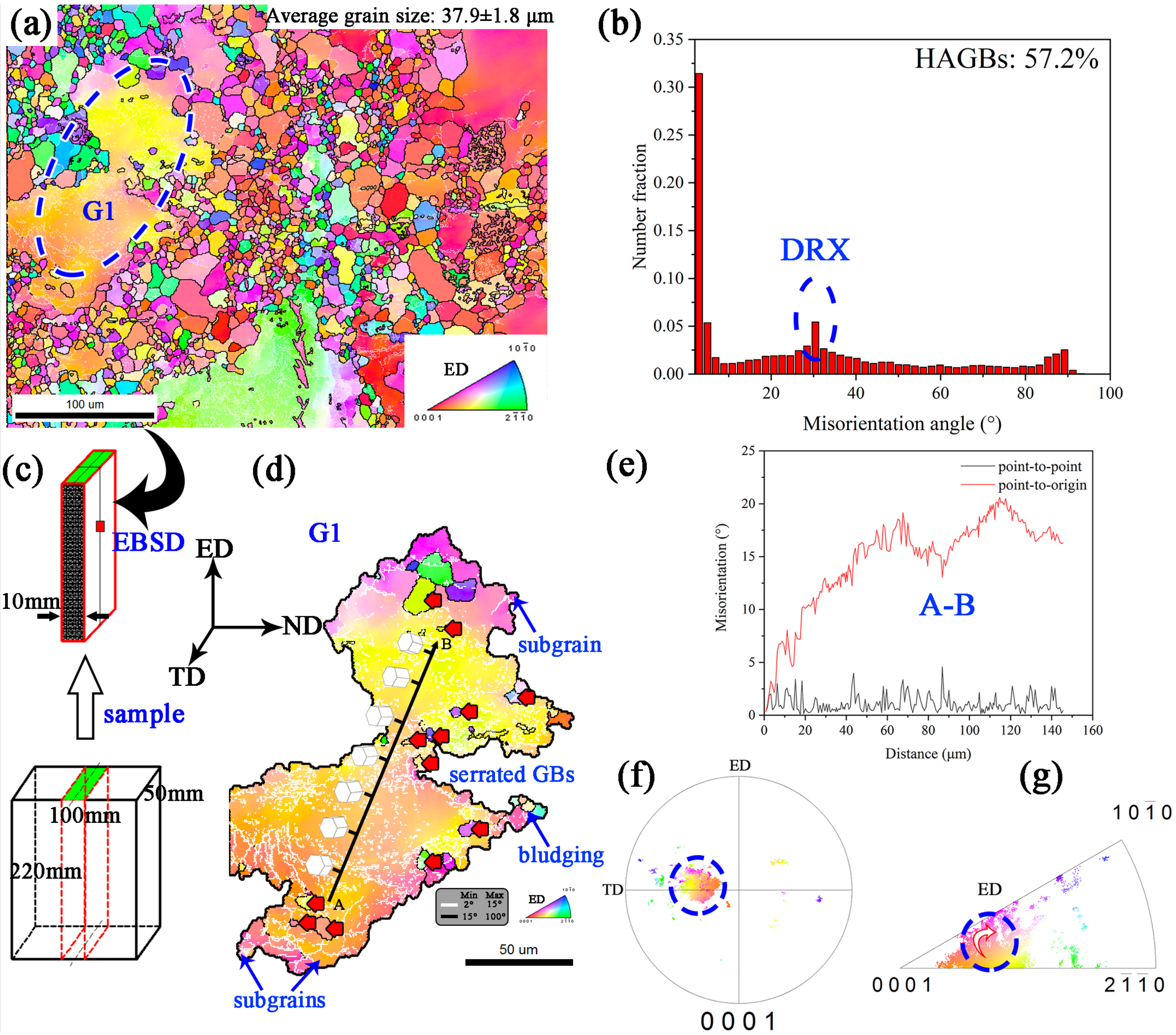
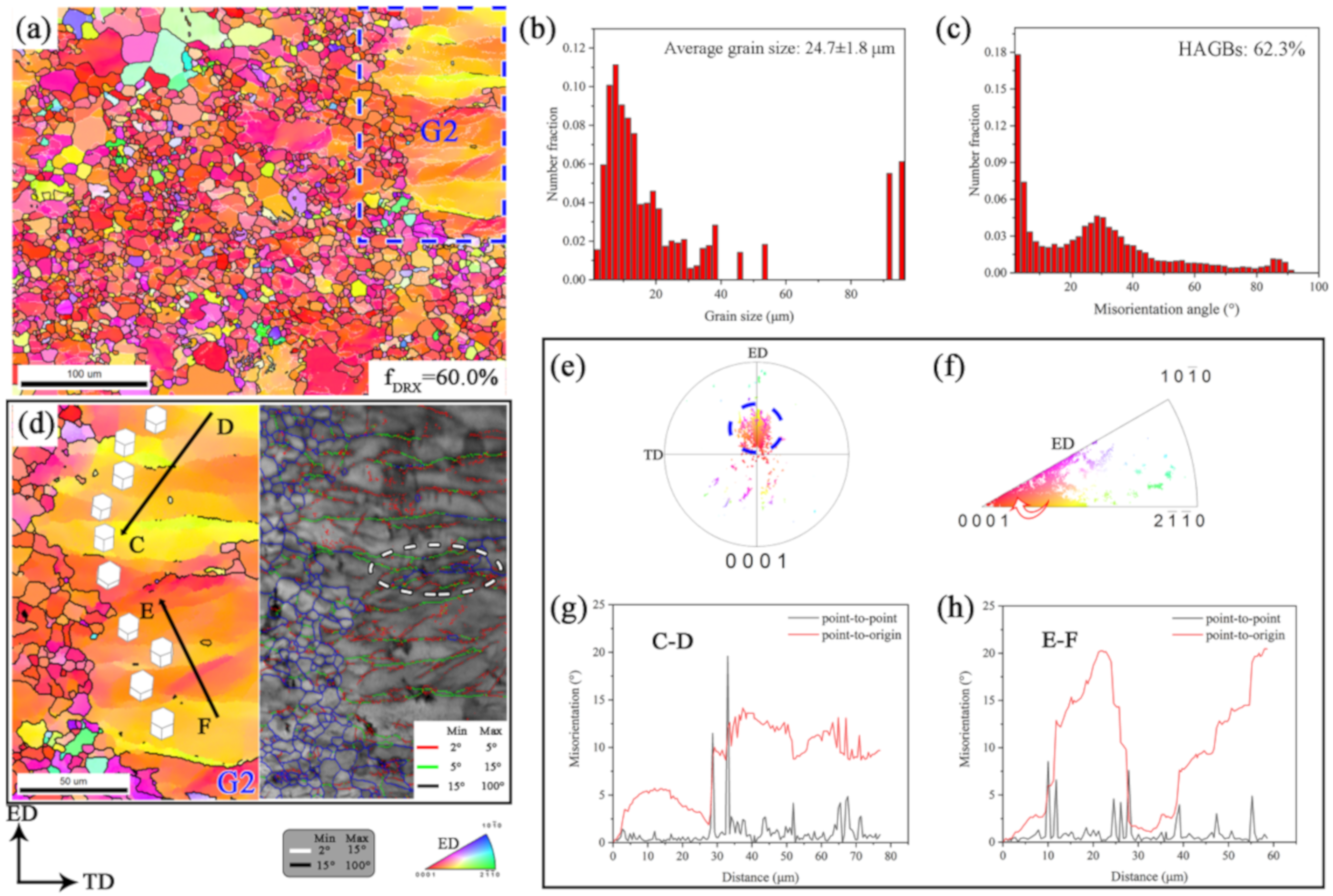
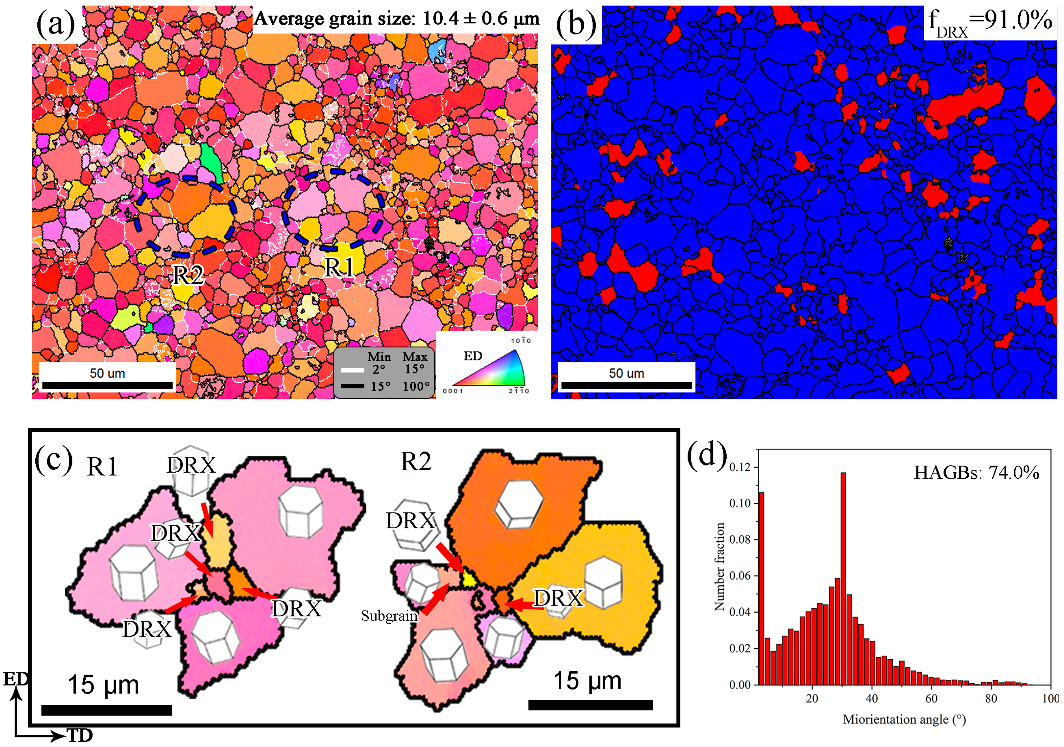
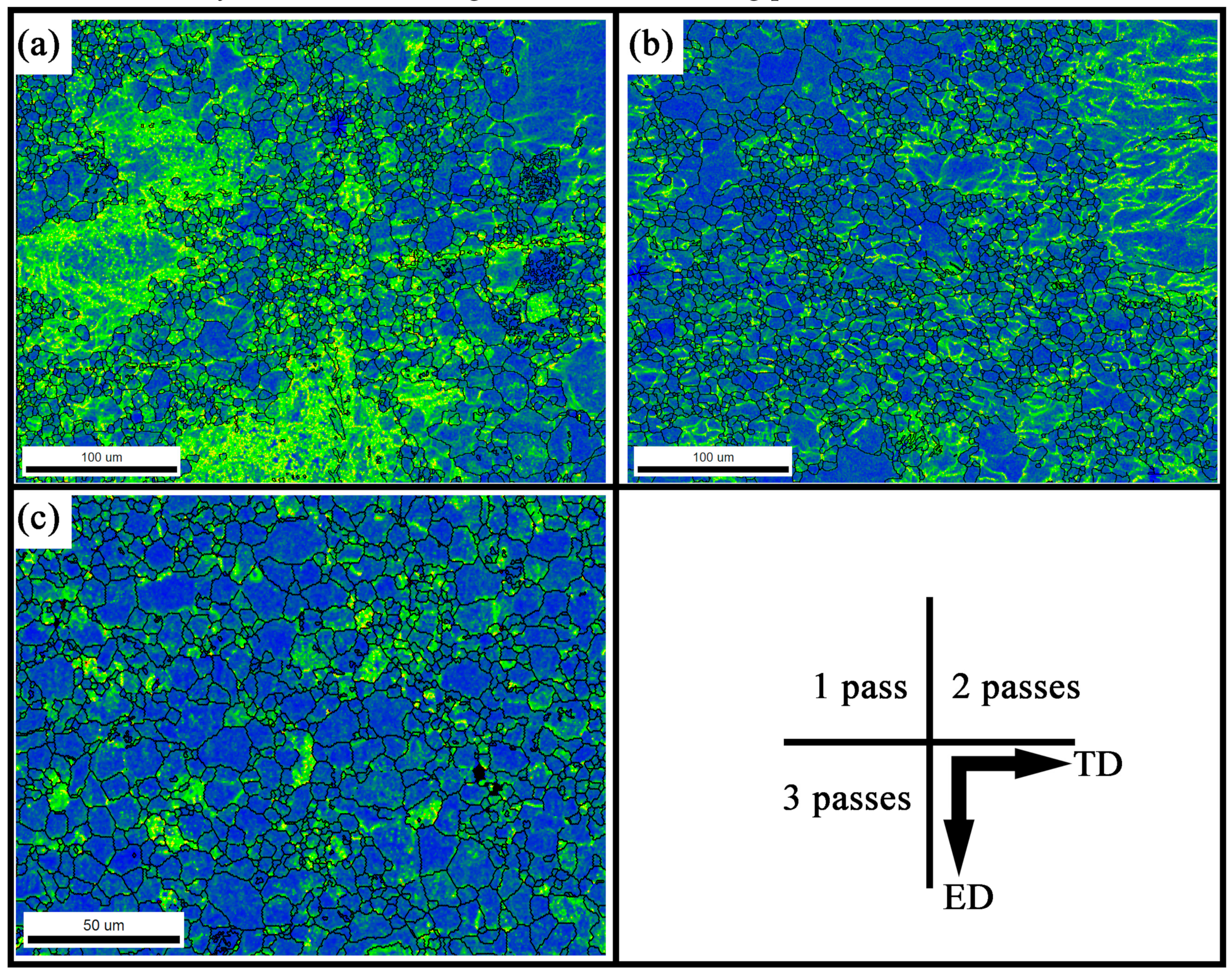
3.2. Microstructure Evolutions

Figure 4 shows the OM microstructures of the CEE-AEC-processed samples with different numbers of passes. After two passes of CEE-AEC, a significant grain refinement was obtained, and the differences at different areas obviously decreased. At the asymmetrical cavity and non-asymmetrical cavity zones, which are represented the P1 and P3, respectively, in Figure 3, there was no existence of coarse grains, and a large number of fine grains (lower than 10 μm) were observed. Such was expected from the DRX that occurred in high strain area due to multi-pass severe plastic deformation. At the center zone, more coarse grains occupied the scanned area, and the heterogeneous microstructure was attributed to the lower accumulative strain than outer areas. Furthermore, a serrated grain boundary was observed along the coarse grain shown in Figure 4b, and it could have been the site for nucleation of dynamic grain through bulging [22]. By increasing CEE-AEC process, the grain structure was further refined and distributed in a relatively homogeneous fashion. The problem of the heterogeneity of a material processed by CEE-AEC was overcome due to the multi-pass deformation. We concluded that the condition of three passes of CEE-AEC was the simplest deformation pattern for obtaining a material with a fine grain structure.
A fully CEE-AEC-processed grain structure based on EBSD technology after one pass is shown in Figure 5. The sample location for analysis is demonstrated in Figure 5c. The EBSD-based microstructure was relatively similar to what we observed with the OM (Figure 3). Coarse grains were mixed together with fine grains to form the heterogeneous structure. A few fine DRX grains formed along the prior coarse grain boundaries, as marked with the blue circle, G1, shown in Figure 5a, resulting in a “necklace” structure. The average grain size was calculated to be 37.9 ± 1.8 μm. A high peak of misorientation angle distribution was seen at 30°, which is a typical characteristic for recrystallization of Mg [23], as shown in Figure 5b. Galiyev et al. [24] and Yi et al. [25] found that DRX grains of Mg alloys nucleated and grew at 30° around the c-axis of the crystal. There were numerous low angle grain boundaries (LAGBs) in the CEE-AEC-processed material. The LAGBs were primarily distributed in the coarse grains, and many subgrains and fine DRX grains could be observed inside coarse grains, as highlighted by the red arrows in Figure 5d. The high angle grain boundaries (HAGBs) were mainly composed of DRX grain boundaries and some coarse grain boundaries. Figure 5d shows the DRX behavior of the deformed grain G1. It can be noticed that G1 mainly consisted of yellow- and orange-colored regions. The line profile of the point-to-point and point-to-origin along the black line AB indicates that the accumulative misorientation, Ʃθ, gradually increased up to 20°, thus showing the continuous change of orientation occurring in G1, as shown in Figure 5e. It can be suggested from Figure 5f,g that the basal plane orientations of the two regions had a gradual change of orientation. This can be further confirmed by the three-dimensional diagram of crystallography along AB in Figure 5d. As usually occurs, the LAGBs trapped mobile dislocations and evolved into HAGBs, eventually achieving fine DRX grains. This is a typical continuous dynamic recrystallization (CDRX) mechanism [26]. Additionally, the subgrains were isolated by sub-GBs, and the coarse grains bowed and bulged corresponding to fine DRX grains that formed the serrated grain boundaries, as shown in Figure 5d. This is defined as discontinuous dynamic recrystallization (DDRX).
Figure 6 shows EBSD-based microstructure of the sample after two passes of CEE-AEC. The grain structure was further refined with an average grain size of 24.7 ± 1.8 μm. The fine recrystallization grains of about 10 μm with HAGBs were evolved near and along coarse grain boundaries. The number fraction of HAGBs was increased to 62.3%. Due to insufficient accumulative strain, orientation gradients were also observed in coarse grain. Herein, some sub-GBs that contained high density dislocations were successfully transformed into HAGBs, resulting in the formation of new GBs, as indicated by the ellipse in Figure 6d. It can be seen that orientation gradient was distinct in coarse grain G2, revealing a high dislocation density in coarse grains of the two passes of deformation; on the other hand, this suggests that CDRX also occurred during the 2 passes of CEE-AEC. The crystallographic orientation of the basal planes of G2 were more inclined than that of the first pass, as shown in Figure 6e,f. This can be attributed to the shear strain that was introduced by attaching an asymmetrical extrusion cavity.
Figure 7 shows the EBSD results of the three passes of the CEE-AEC-processed sample. The DRX fraction markedly increased to 91.0%, but the grain structures were relatively homogeneous, though not equiaxed, as shown in Figure 7a,b. Thus, we know that the DRX process that occurred during the three passes of CEE-AEC did not fully take place, especially in the recrystallized region. For a better understanding of the DRX behavior in the recrystallized region, typical regions R1 and R2 are selected in Figure 7a, and the results of their processing are shown in Figure 7c. It can be seen that fine DRX grains nucleated at serrated GBs and at the triple junctions of the previous DRX grains, indicating the consecutive occurrence of DDRX in the recrystallized region. The DDRX grains had evidently deviated orientations, as can be seen by them surrounding recrystallized grains without preferred selection. Thus, we can conclude that the DDRX played dominant role in the microstructural evolution during three passes of CEE-AEC.
Table 1 summarizes the evolution of grain size, the DRX fraction, HAGBs, and LAGBs. A significant grain refinement was observed from initial grain size of more than 300 to 10.4 ± 0.6 μm after three passes. Meanwhile, the DRX fraction markedly increased to 91.0% with the increasing number of CEE-AEC passes. Furthermore, the HAGB fraction was observed to continuously increase to 74.0% by the end of the three passes of CEE-AEC, corresponding to a continuous decrease in LAGBs.
Figure 8 shows the kernel average misorientation (KAM) maps of the AZ31B samples after different numbers of CEE-AEC passes. Usually, KAMs are used to explain the local residual strain concentration and dislocation density in a processed alloy, and different colors that transition from blue to red represent the increasing degree of strain and dislocation concentration [27]. After one pass of CEE-AEC, as illustrated in Figure 8a, it can be noticed that yellow and green regions mainly occupied the coarse deformed grains and their grain boundaries. Due to the accumulative strain from CEE-AEC, residual strain and dislocations began to generate and accumulate. Meanwhile, the newly formed DRX grains, which are presented in blue, indicated the lower dislocation accumulation compared to that of the deformed grains. The volume fraction of DRX increased with the increasing number of CEE-AEC passes, and a large number of dislocations was consumed in the recrystallization process. A comparatively homogeneous microstructure was observed after three passes of deformation, and the scanned area was occupied by blue areas, thus indicating a much lower strain concentration compared to the first CEE-AEC pass. Thus, the CEE-AEC-processed alloy remained in a steady state, which was good for the following process.

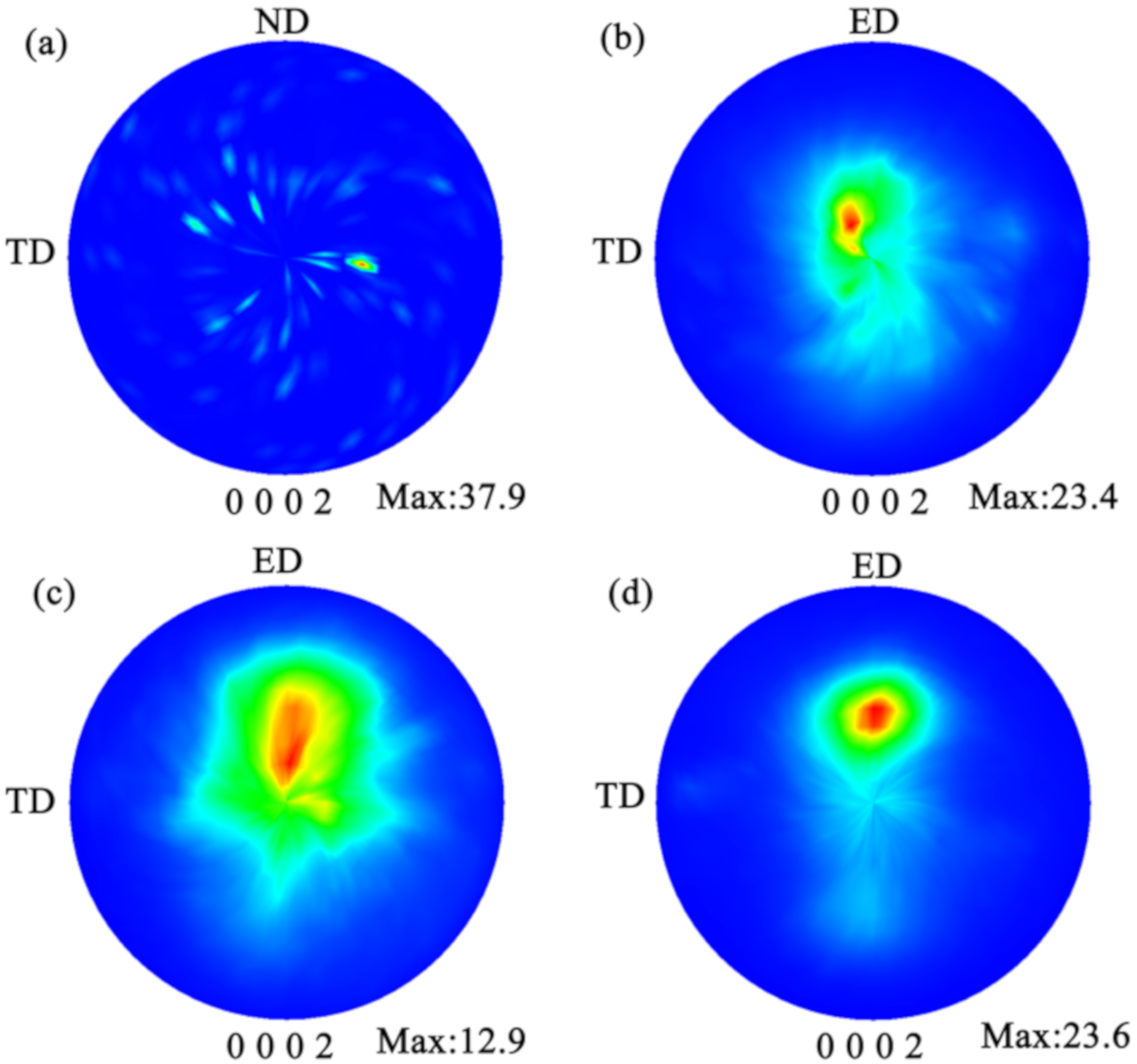
3.3. Texture Evolutions

The (0001) and (10 1 ¯ 0) pole figures of samples based on EBSD results after different numbers of CEE-AEC passes are shown in Figure 9. After one pass of CEE-AEC, as shown in Figure 9a, an inclined basal texture with 0–20° spreading from TD to ED was observed. This was attributed to the shear deformation introduced by the asymmetrical extrusion cavity. The appearance of this non-basal texture component was investigated by Chang et al. [16] and Xu et al. [17,18]. Furthermore, due to the occurrence of DRX, the concentrated basal poles began to spread over a large angular from ED to TD. With further CEE-AEC passes, as shown in Figure 9b,c, the samples showed a more obvious inclined texture, with the (0001) planes of most grains being parallel and inclined ~45° to ED. Moreover, the basal poles were more concentrated, and the maximum intensity increased with the increasing number of CEE-AEC passes.
In order to avoid the limitation of micro-area EBSD texture for understanding the orientation behavior of the AZ31B alloys during the CEE-AEC process, a further investigation of macro-area (0002) pole figure from XRD measurements was carried out, and the results are shown in Figure 10. In general, the global texture presented a similar situation to that of the EBSD-based micro-area texture. The homogenized sample showed a random texture, as shown in Figure 10a. After CEE-AEC, the grains presented a preferred orientation, which was different from the typical fiber texture processed by conventional axisymmetric extrusion. The c-axes of most grains inclined at an angle of 5–45° with the ED. Moreover, due to the increasing volume fraction of DRX, the spreading of the basal planes of most grains and a weak intensity were observed after two passes of CEE-AEC, as shown in Figure 10c. However, the high accumulative strain after three passes of deformation resulted in a further increase of the titling angle and intensity, as shown in Figure 10d.

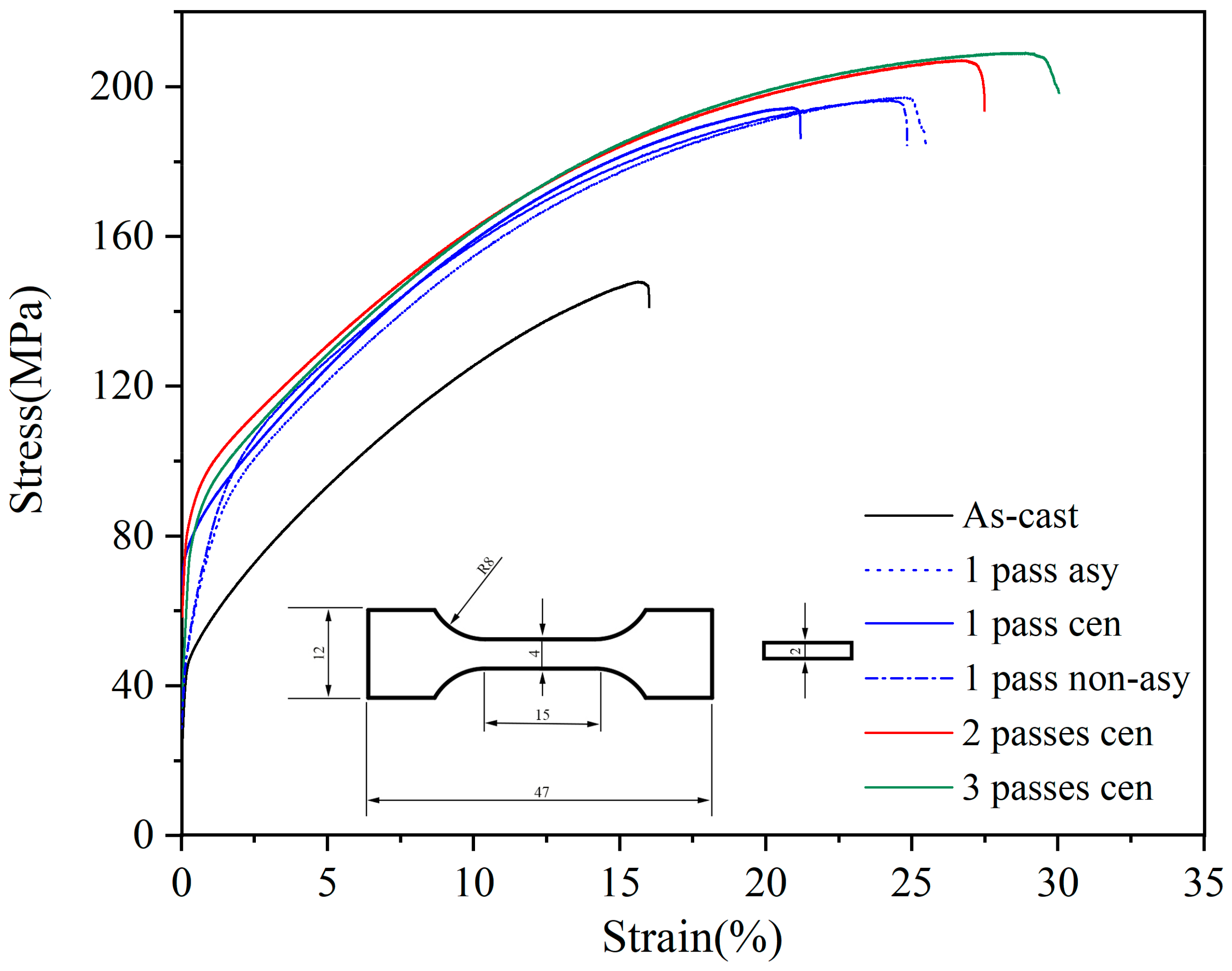
3.4. Mechanical Properties

The room temperature mechanical properties of the as-cast and CEE-AEC-processed samples are shown in Figure 11, and the values of ultimate tensile strength (UTS), tensile yield strength (TYS), and elongation to failure (EF) are listed in Table 2. The abbreviations of “asy,” “cen,” and “non-asy” represent the selected areas for tensile tests, and they are “asymmetrical area,” “center area,” and “non-asymmetrical area,” respectively. The as-cast alloy showed the lowest tensile properties, both in strength and ductility. The UTS, TYS, and EF were 148 ± 5 MPa, 65 ± 4 MPa, and 15.7 ± 0.8%, respectively. After two passes of CEE-AEC, the mechanical properties showed an obviously increasing tendency. In particular, after one pass, the values of UTS and TYS in the center zone of the CEE-AEC-processed sample presented a dramatic increase to 194 ± 2 and 94 ± 2 MPa, respectively, and the mechanical anisotropy that resulted from the heterogeneous microstructure showed better tensile properties in the asymmetrical area than in the non-asymmetrical area; the center area had the worst tensile properties. After three passes of CEE-AEC, the UTS and TYS remained steady in comparison those after two passes, while the EF increased rapidly to 30.0 ± 1.3%. From the observation of microstructure and the calculation of average grain size, it was concluded that the superior mechanical properties corresponded to the fine and uniform grain structure. The specific mechanical mechanisms are discussed in the following section.

4. Discussion

The experiment results of the CEE-AEC provide important information concerning the effects of grain refinement and texture modification on the alloy’s mechanical properties. Hence, understanding the relationship and competitive mechanisms of the microstructure and texture evolution of Mg alloys prepared by CEE-AEC is of significant importance for designing a test to obtain samples with superior mechanical properties in the future.

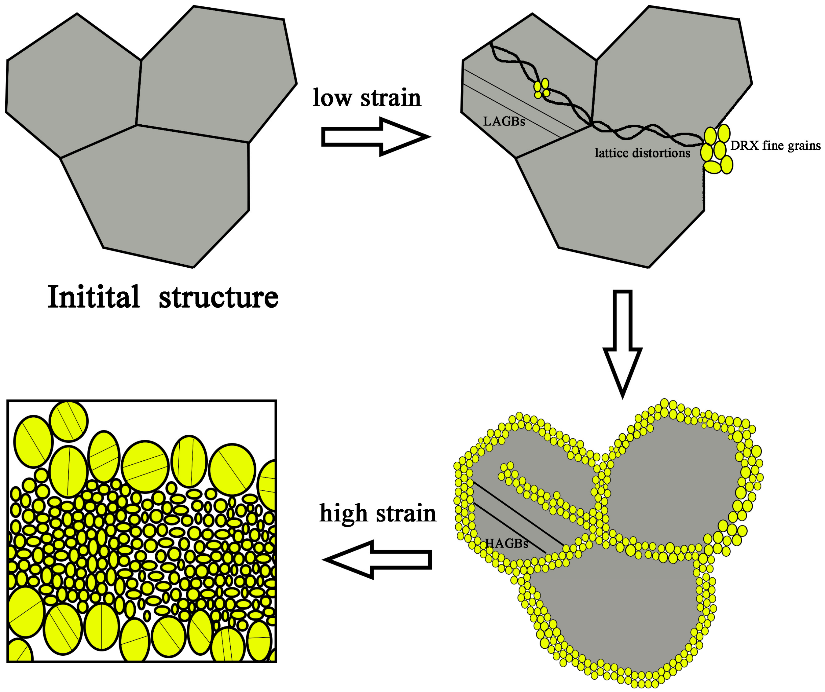
4.1. Grain Refinement during CEE-AEC

Several mechanisms for an Mg alloy to achieve grain refinement have been reported in the literature. Li et al. [27] proposed that the grain structure evolution of Mg–Gd–Y–Zn–Zr alloys during ECAP is due to the transformation from LAGBs into HAGBs, as well as the particle-stimulated nucleation (PSN) mechanism. Miura et al. [28] explained that the grain refinement mechanisms of AZ61 alloys fabricated by multidirectional forging (MDF) were determined by temperature. Twinning and CDRX were combined to refine grain structures during MDF processing with a decreasing temperature. Zhang et al. [29] investigated the DRX behavior of an Mg–Zn–Y–Zr alloy using hot compression tests. They found that DDRX firstly occurred on the original grain boundaries. As further deformation was carried out, CDRX took place inside the original grains. Ma et al. [30] reported twinning-induced dynamic recrystallization in an Mg alloy.
In our work, the dynamic recrystallization mechanism was the dominant mechanism in grain refinement. Twinning and deformation bands were rarely found in the evolved microstructures due to the high deformation temperature.
The dynamic recrystallization mechanisms in Mg alloys can be divided into two groups: CDRX and DDRX. The continuous absorption of dislocations in sub-GBs is the main characteristic of CDRX, while DDRX grains nucleate and grow via the migration of HAGBs. As discussed above, it can be concluded that CDRX and DDRX play important roles in grain refinement during CEE-AEC. Figure 12 shows DRX behavior in different stages.
In first stage of the CEE-AEC process, DRX fine grains with grain size smaller than 10 μm were observed, both within the coarse grains and along serrated grain boundaries. Discontinuous dynamic recrystallized grains showed no distinct gradients, either in recrystallized grains or in the original grains, while continuous dynamic recrystallized grains resulted from the progressive rotation of subgrains adjacent to preexisting grain boundaries. Thus, it can be concluded that the dominant mechanism of Mg alloys prepared by CEE-AEC to achieve grain refinement at low and medium strains is a combination of CDRX and DDRX.
At second stage of the CEE-AEC process with higher accumulative strain (three passes of CEE-AEC), the coarse grains were consumed by recrystallized grains, but they were not equiaxial. Fine grains could also be observed at recrystallized regions, especially at the triple junctions of the DRX grains. Thus, it can be known that the CDRX mechanism is not a dominant force refining grain structure, and DDRX determines further grain refinement.

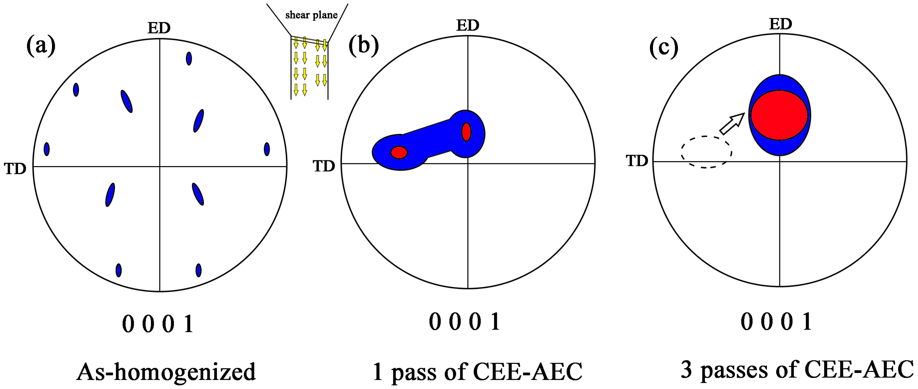
4.2. Texture Evolution Mechanism

The ductility of an Mg alloy at room temperature is mainly related to its activated slips. In Mg alloys, basal <a> slip systems predominate, although the prismatic slip operated for grains is oriented to suppress the basal slip. The modification of the texture component during the SPD process can affect the activation of basal <a> slips. Kim et al. [11,31] and Tong et al. [32] found that the shear deformation provided from ECAP could inform the basal inclination texture, which was proven to be helpful in improving the ductility.
In the present work, the introduction of an asymmetrical extrusion cavity changed the crystallographic orientation of most grains, and a mixed texture component was obtained. Figure 13 shows a schematic image of the texture evolution during CEE-AEC. The red color represents a more concentrated orientation distribution, and the blue area represents a dispersion texture. As seen in Figure 13a, the initial structure was mainly composed of random orientated grains, and the random texture was remarkably changed after one pass of CEE-AEC, as shown in Figure 13b. An obvious mixed texture component occurred, with basal planes parallel and inclined from TD to ED, due to the shear deformation at the asymmetrical extrusion cavity. The phenomenon of TD spread has been reported in many studies and may be related to the DRX mechanism, which intensifies the dispersion of basal textures [14,22,27,33]. After three passes, as shown in Figure 13c, the orientations of most grains were redistributed, and the basal planes were inclined ~45° to ED.

4.3. Strengthening Mechanisms

In Figure 14, the tensile yield strength is plotted against d−1/2 for the as-cast and CEE-AEC-processed samples. The solid circle indicates the data for the cast material, and the solid squares represent the points for the CEE-AEC-processed samples. The standard Hall–Petch relationship with a positive slope was valid in the data for the samples from the state of homogenization to two passes of CEE-AEC. Meanwhile, these points were well-correlated to a single line. For the three-pass sample, however, the slope of tensile yield stress versus d−1/2 obviously declined. Kim et al. [11] found that the tensile stress of Al alloys subject to ECAP is mainly determined by grain size, but Mg alloys subject to ECAP did not behave in the same way. In subsequent studies, they found that the tensile stress of Mg alloys subject to ECAP was notably lower than that of the extruded alloys with the same grain size; texture modification was responsible for these results.
In general, the room temperature mechanical properties of the AZ31 alloys in the present research were mainly dependent on the grain size and texture modification. From Table 2 and Figure 14, it can be seen that the TYS increased and the average grain size decreased with the increasing number of CEE-AEC passes. The appearance of non-standard Hall–Petch relationship demonstrated the competition of grain refinement strengthening and texture modification.
During the two-pass deformation of CEE-AEC, an obvious linear increase relation in yield strength and a linear decrease relation in grain sizes were observed, as shown in Figure 14. Moreover, the sample after two passes of CEE-AEC presented an embryonic form of the basal inclination texture. This suggested that the determination of TYS in the first two passes of CEE-AEC was predominately controlled by grain refinement strengthening. Additionally, another piece of evidence that proves this conclusion was the relationship between TYS and grain sizes in different processing areas. As shown in Figure 11, the finer grain structure in asymmetrical areas showed better properties than the non-asymmetrical and center areas.
The CEE-AEC-processed AZ31B alloys, after three passes with a grain size of 10.4 ± 0.6 μm, had almost the same TYS as the sample that went through two passes. This was because the basal texture of the CEE-AEC-processed AZ31 alloy showed an inclination of ~45° from TD to ED. The basal inclination texture made grains with soft orientations for the operation of basal <a> slips at room temperature. Figure 15 shows the EBSD analysis of the Schmid factor for the (0001) <11 2 ¯ 0> slip system of the CEE-AEC-processed samples loading along the ED. The higher Schmid factor value meant a lower tensile yield strength in the same conditions. This was because a high Schmid factor leads to a low stress for the activation of basal slip and material yielding [34]. From the quantitative analysis of Schmid factor during CEE-AEC, as shown in Figure 15, it can be seen that an increasing value of Schmid factor from 0.22 to 0.32 was obtained due to the shear deformation, which redistributed the texture component and formed a typical texture with inclined c-axis of most grains towards ED. The sample after three passes of CEE-AEC was more favorable for the dislocation glide on (0001) plane. Thus, it can be concluded that the determination of TYS of the sample after three passes of deformation was mainly controlled by texture modification rather than grain refinement strengthening.
It was clearly seen that the elongation the AZ31B alloys processed by CEE-AEC was remarkably improved, achieving a good balance of strength and ductility. A fractography analysis is shown in Figure 16. A lot of cleavage steps and tear ridges were observed on the surface of the as-cast alloy, implying that the main fracture mechanism was cleavage damage, which resulted in a poor ductility, as shown in Figure 16a. After one pass of CEE-AEC, the refined grain structure and the increasing volume fraction of the fine DRX grains effectively hindered the cleavage damage. The number of cleavage steps and tear ridges obviously decreased, and many dimples were observed on the fracture surfaces, representing cleavage mixed with ductile fracture behavior, as shown in Figure 16b. With the increasing passes, the coarse grains were consumed, and a more homogeneous grain structure with a basal inclination texture was obtained. Meanwhile, the increasing Schmid factor value promoted the activation of the basal <a> slip system. As shown in Figure 16c,d, the fracture surfaces were occupied by a large number of dimples, thus showing a typical ductile fracture behavior. The improvement of the ductility of the CEE-AEC-processed alloy was related to grain refinement and the formation of a basal inclination texture. The increasing volume fraction grain boundary restricted the required energy of crack growth, and the activation of the basal slip system promoted the slide of the high density of dislocation formed during the tensile experiments.
The CEE-AEC-processed AZ31B alloys were found to achieve a dramatic grain refinement from >300 to 10.4 ± 0.6 μm for the as-cast to the three-passed alloys, respectively. The refinement degree was more than ~96%. Moreover, the TYS and ductility were increased by ~95% and ~100%, respectively. The excellent elongation of the sample after three passes of deformation (30.0 ± 1.3%) was mainly dominated by a refined and homogeneous grain structure, as well as the formation of a basal inclination texture. The introduction of an asymmetrical extrusion cavity effectively improved the homogeneity of the microstructure and modified the texture component.

5. Conclusions

In present research, AZ31B alloys with homogeneous grain structures and enhanced ductility were successfully fabricated by a novel SPD technology: CEE-AEC. The corresponding DRX behavior, texture evolution and strengthening mechanisms were systematically discussed. The following main observations occurred in this study.
(1).
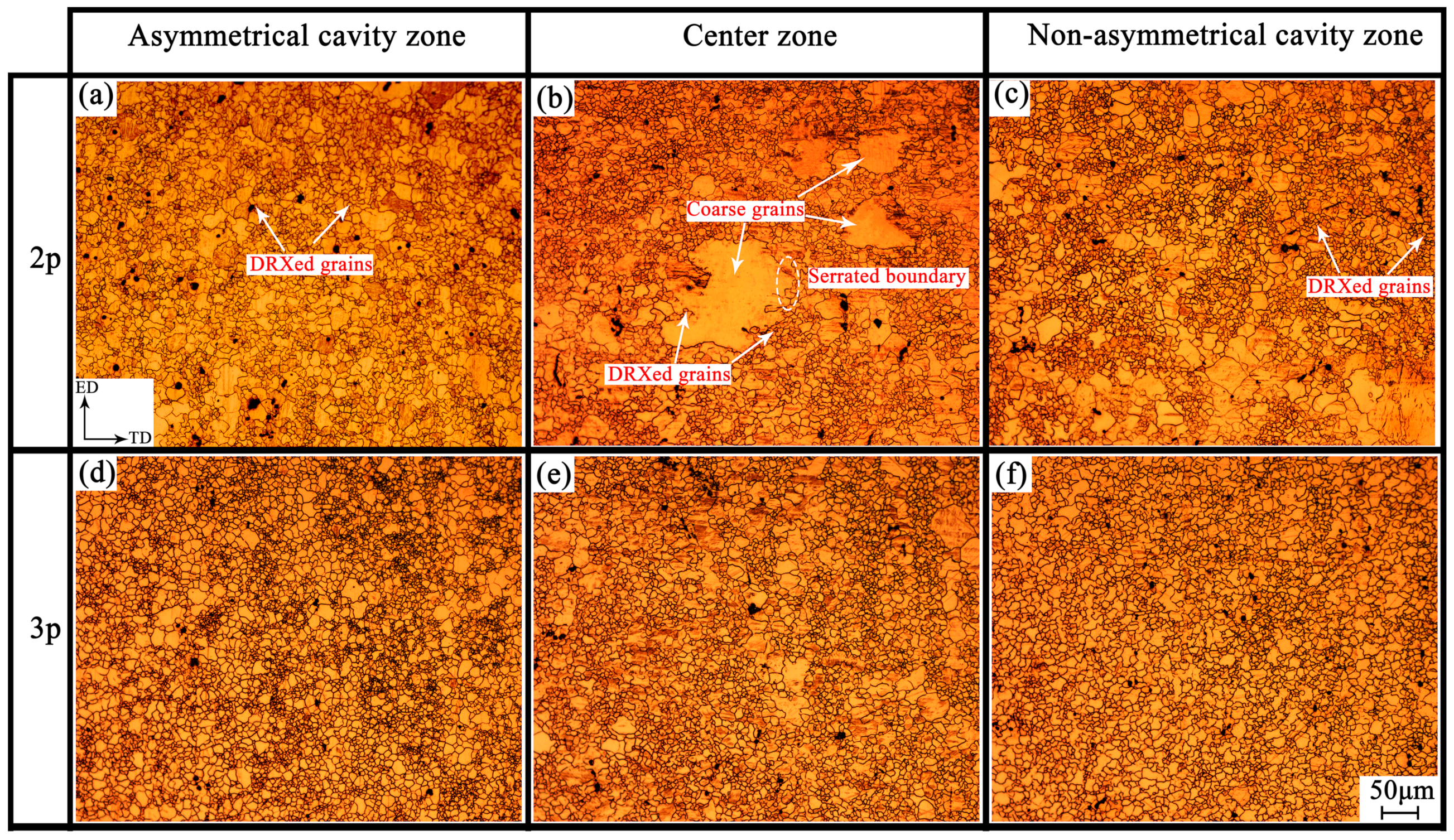
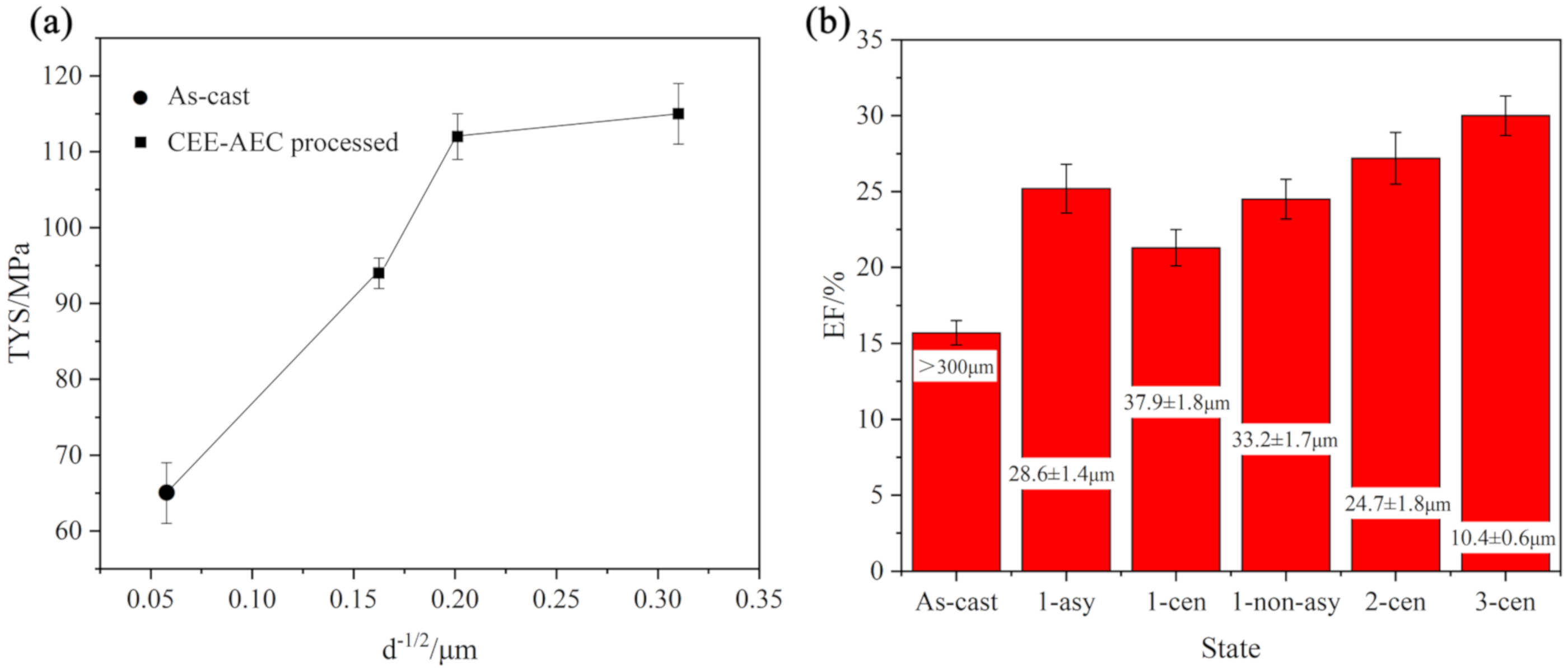
CEE-AEC could effectively refine grain structure and improve microstructure homogeneity, mainly via DRX. CDRX and DDRX acted on the first two passes of deformation, and DDRX further refined the microstructure after three passes. Finally, a homogenous microstructure with an average grain size of 10.4 ± 0.6 μm was observed, and the grain refinement degree in comparison with the as-cast alloys was more than ~96%.
(2).
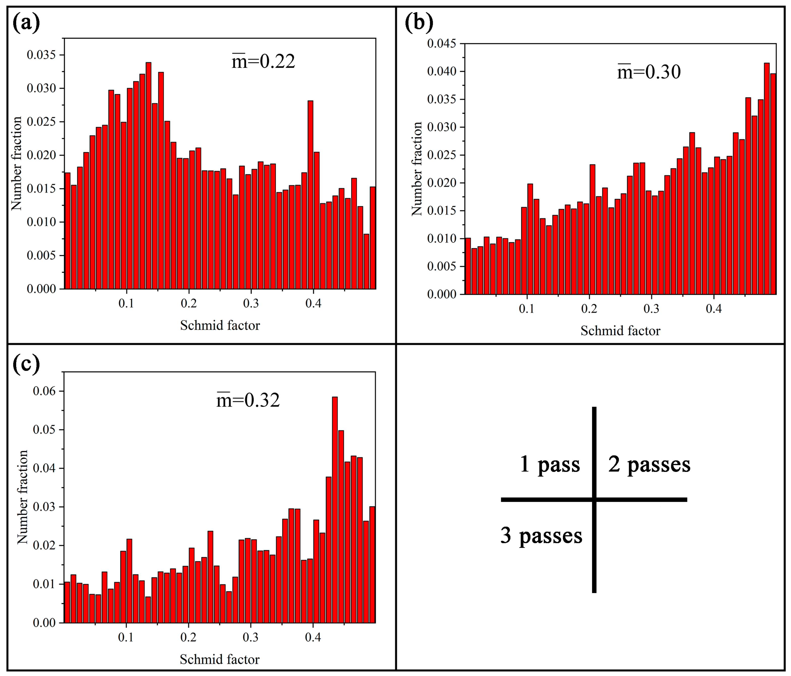
The texture characterization after CEE-AEC revealed a basal inclination texture, with (0001) planes inclined ~45° to the ED. With further CEE-AEC processing, the typical basal texture rotation resulted in an asymmetric texture corresponding to an increasing Schmid factor.
(3).
The tensile properties of the CEE-AEC-processed samples were remarkably improved, with the UTS, TYS, and EF of the as-cast alloys being 148 ± 5 MPa, 65 ± 4 MPa, 15.7 ± 0.8%, respectively, and the same qualities of three passes being 209 ± 2 MPa, 115 ± 4 MPa, and 30.0 ± 1.3%, respectively. The formed basal inclination texture facilitated the activation of basal <a> slip systems, and the TYS of the three pass-deformation showed a slight improvement in comparison with the two pass-deformation.
(4).
Grain refinement strengthening and texture modification were the main strengthening mechanisms. The competition between the two mechanisms influenced the whole CEE-AEC process. During the first two passes of deformation, grain refinement was the dominant way of improving the tensile strength. Texture modification determined the high ductility after three passes of deformation.

6. Patents

In order to protect the intellectual property rights, the CEE-AEC technology is patented with the number of CN201910324749.4 of China.

Author Contributions

Z.Z. and Y.X. designed the experiments; Z.Y. and J.Z. (Jie Zheng) performed the experiments and collected the data; Z.Y., Q.W., and J.Z. (Jiaxuan Zhu) analyzed the data; Z.Y. wrote the paper. All authors have read and agreed to the published version of the manuscript.

Funding

The present study was supported by the National Natural Science Foundation of China (NSFC) under Grant no. 51775520 and no. 51675492, the Natural Science Foundation of Shanxi Province under Grant no. 201801D121106, the Key R&D program of Shanxi Province (International Cooperation) under grant No. 201903D421036, and the Scientific and Technological Innovation Programs of Higher Education Institutions in Shanxi under grant No. 2018002.

Conflicts of Interest

The authors declare that they have no conflict of interest.

References

  1. Foley, D.; Al-Maharbi, M.; Hartwig, K.T.; Karaman, I.; Kecskes, L.J.; Mathaudhu, S. Grain refinement vs. crystallographic texture: Mechanical anisotropy in a magnesium alloy. Scr. Mater. 2011, 64, 193–196. [Google Scholar] [CrossRef] [Green Version]
  2. Zheng, J.; Yan, Z.; Yu, J.; Zhang, Z.; Fan, H.; Xu, K.; Xue, Y. Microstructure and mechanical properties of Mg-Gd-Y-Zn-Zr alloy by cyclic expansion-extrusion with an asymmetrical extrusion cavity (CEE-AEC). Mater. Res. Express 2019, 6, 1065c8. [Google Scholar] [CrossRef]
  3. Yan, Z.; Fang, M.; Lian, Z.; Zhang, Z.; Zhu, J.; Zhang, G.; Wang, Y. Research on AZ80 + 0.4%Ce (wt%) Ultra-Thin-Walled Tubes of Magnesium Alloys: The Forming Process, Microstructure Evolution and Mechanical Properties. Metals 2019, 9, 563. [Google Scholar] [CrossRef] [Green Version]
  4. Xue, Y.; Chen, S.; Liu, H.; Zhang, Z.; Ren, L.; Bai, B. Effect of Cyclic Expansion-Extrusion Process on Microstructure, Deformation and Dynamic Recrystallization Mechanisms, and Texture Evolution of AZ80 Magnesium Alloy. Adv. Mater. Sci. Eng. 2019, 2019, 1–10. [Google Scholar] [CrossRef] [Green Version]
  5. Zhang, Z.; Yan, Z.; Du, Y.; Zhang, G.; Zhu, J.; Ren, L.; Wang, Y. Hot Deformation Behavior of Homogenized Mg-13.5Gd-3.2Y-2.3Zn-0.5Zr Alloy via Hot Compression Tests. Materials 2018, 11, 2282. [Google Scholar] [CrossRef] [PubMed] [Green Version]
  6. Yan, Z.M.; Zhang, Z.M.; Du, Y.; Zhang, G.S.; Ren, L.Y. Effect of homogenization treatment on microstructure and mechanical properties of Mg-13Gd-3.5Y-2Zn-0.5Zr magnesium alloy. J. Mater. Eng. 2019, 47, 93–99. [Google Scholar]
  7. You, S.; Huang, Y.; Kainer, K.U.; Hort, N. Recent research and developments on wrought magnesium alloys. J. Magnes. Alloy. 2017, 5, 239–253. [Google Scholar] [CrossRef]
  8. Valiev, R.Z.; Islamgaliev, R.; Alexandrov, I. Bulk nanostructured materials from severe plastic deformation. Prog. Mater. Sci. 2000, 45, 103–189. [Google Scholar] [CrossRef]
  9. Suh, J.; Victoria-Hernández, J.; Letzig, D.; Golle, R.; Volk, W. Effect of processing route on texture and cold formability of AZ31 Mg alloy sheets processed by ECAP. Mater. Sci. Eng. A 2016, 669, 159–170. [Google Scholar] [CrossRef]
  10. Lee, H.-J.; Lee, S.K.; Jung, K.H.; Lee, G.A.; Ahn, B.; Kawasaki, M.; Langdon, T.G. Evolution in hardness and texture of a ZK60A magnesium alloy processed by high-pressure torsion. Mater. Sci. Eng. A 2015, 630, 90–98. [Google Scholar] [CrossRef]
  11. Kim, W.; Hong, S.; Kim, Y.; Min, S.; Jeong, H.; Lee, J. Texture development and its effect on mechanical properties of an AZ61 Mg alloy fabricated by equal channel angular pressing. Acta Mater. 2003, 51, 3293–3307. [Google Scholar] [CrossRef]
  12. Stráská, J.; Janeček, M.; Gubicza, J.; Krajňák, T.; Yoon, E.Y.; Kim, H.S. Evolution of microstructure and hardness in AZ31 alloy processed by high pressure torsion. Mater. Sci. Eng. A 2015, 625, 98–106. [Google Scholar] [CrossRef]
  13. Iwahashi, Y.; Wang, J.; Horita, Z.; Nemoto, M.; Langdon, T.G. Principle of equal-channel angular pressing for the processing of ultra-fine grained materials. Scr. Mater. 1996, 35, 143–146. [Google Scholar] [CrossRef]
  14. Yan, Z.; Zhang, Z.; Li, X.; Xu, J.; Wang, Q.; Zhang, G.; Zheng, J.; Fan, H.; Xu, K.; Zhu, J.; et al. A novel severe plastic deformation method and its effect on microstructure, texture and mechanical properties of Mg-Gd-Y-Zn-Zr alloy. J. Alloys Compd. 2020, 822, 153698. [Google Scholar] [CrossRef]
  15. Beygelzimer, Y.; Kulagin, R.; Estrin, Y.; Toth, L.S.; Kim, H.S.; Latypov, M.I. Twist Extrusion as a Potent Tool for Obtaining Advanced Engineering Materials: A Review. Adv. Eng. Mater. 2017, 19, 1600873. [Google Scholar] [CrossRef]
  16. Chang, L.; Wang, Y.; Zhao, X.; Huang, J.C. Microstructure and mechanical properties in an AZ31 magnesium alloy sheet fabricated by asymmetric hot extrusion. Mater. Sci. Eng. A 2008, 496, 512–516. [Google Scholar] [CrossRef]
  17. Xu, J.; Jiang, B.; Song, J.; He, J.; Gao, P.; Liu, W.; Yang, T.; Huang, G.; Pan, F. Unusual texture formation in Mg–3Al–1Zn alloy sheets processed by slope extrusion. Mater. Sci. Eng. A 2018, 732, 1–5. [Google Scholar] [CrossRef]
  18. Xu, J.; Yang, T.B.; Jiang, B.; Song, J.F.; He, J.J.; Wang, Q.H.; Chai, Y.F.; Huang, G.S.; Pan, F.S. Improved mechanical properties o Mg-3Al-1Zn alloy sheets by optimizing the extrusion die angles: Microstructural and texture evolution. J. Alloys Compd. 2018, 762, 719–729. [Google Scholar] [CrossRef]
  19. Liu, X.-Y.; Lu, L.; Sheng, K.; Zhou, T. Microstructure and Texture Evolution during the Direct Extrusion and Bending–Shear Deformation of AZ31 Magnesium Alloy. Acta Metall. Sin. (Engl. Lett.) 2018, 32, 710–718. [Google Scholar] [CrossRef] [Green Version]
  20. Beausir, B.; Suwas, S.; Toth, L.S.; Neale, K.W.; Fundenberger, J.-J. Analysis of texture evolution in magnesium during equal channel angular extrusion. Acta Mater. 2008, 56, 200–214. [Google Scholar] [CrossRef]
  21. Su, C.W.; Lu, L.; Lai, M.O. Mechanical behaviour and texture of annealed AZ31 Mg alloy deformed by ECAP. Mater. Sci. Technol. 2007, 23, 290–296. [Google Scholar] [CrossRef]
  22. Zhang, Z.; Meng, Y.; Yan, F.; Gao, Z.; Yan, Z.; Zhang, Z. Microstructure and texture evolution of Mg-RE-Zn alloy prepared by repetitive upsetting-extrusion under different decreasing temperature degrees. J. Alloys Compd. 2020, 815, 152452. [Google Scholar] [CrossRef]
  23. Lei, W.; Liang, W.; Wang, H.; Sun, Y. Effect of annealing on the texture and mechanical properties of pure Mg by ECAP at room temperature. Vacuum 2017, 144, 281–285. [Google Scholar] [CrossRef]
  24. Galiyev, A.; Kaibyshev, R.; Gottstein, G. Correlation of plastic deformation and dynamic recrystallization in magnesium alloy ZK60. Acta Mater. 2001, 49, 1199–1207. [Google Scholar] [CrossRef]
  25. Yi, S.-B.; Zaefferer, S.; Brokmeier, H.-G. Mechanical behaviour and microstructural evolution of magnesium alloy AZ31 in tension at different temperatures. Mater. Sci. Eng. A 2006, 424, 275–281. [Google Scholar] [CrossRef]
  26. Jiang, M.; Xu, C.; Yan, H.; Fan, G.; Nakata, T.; Lao, C.; Chen, R.; Kamado, S.; Han, E.-H.; Lu, B. Unveiling the formation of basal texture variations based on twinning and dynamic recrystallization in AZ31 magnesium alloy during extrusion. Acta Mater. 2018, 157, 53–71. [Google Scholar] [CrossRef]
  27. Li, B.; Teng, B.; Chen, G. Microstructure evolution and mechanical properties of Mg-Gd-Y-Zn-Zr alloy during equal channel angular pressing. Mater. Sci. Eng. A 2019, 744, 396–405. [Google Scholar] [CrossRef]
  28. Miura, H.; Yu, G.; Yang, X. Multi-directional forging of AZ61Mg alloy under decreasing temperature conditions and improvement of its mechanical properties. Mater. Sci. Eng. A 2011, 528, 6981–6992. [Google Scholar] [CrossRef]
  29. Zhang, Y.; Zeng, X.; Lu, C.; Ding, W. Deformation behavior and dynamic recrystallization of a Mg–Zn–Y–Zr alloy. Mater. Sci. Eng. A 2006, 428, 91–97. [Google Scholar] [CrossRef]
  30. Ma, Q.; Li, B.; Marin, E.B.; Horstemeyer, S.J. Twinning-induced dynamic recrystallization in a magnesium alloy extruded at 450 °C. Scr. Mater. 2011, 65, 823–826. [Google Scholar] [CrossRef]
  31. Kim, W.J.; Kim, J.K.; Park, T.Y.; Hong, S.I.; Kim, D.I.; Kim, Y.S.; Lee, J.D. Enhancement of strength and superplasticity in a 6061 Al alloy processed by equal-channel-angular-pressing. Metall. Mater. Trans. A 2002, 33, 3155–3164. [Google Scholar] [CrossRef]
  32. Tong, L.; Chu, J.; Jiang, Z.; Kamado, S.; Zheng, M. Ultra-fine grained Mg-Zn-Ca-Mn alloy with simultaneously improved strength and ductility processed by equal channel angular pressing. J. Alloys Compd. 2019, 785, 410–421. [Google Scholar] [CrossRef]
  33. Tang, L.; Liu, C.; Chen, Z.; Ji, D.; Xiao, H. Microstructures and tensile properties of Mg–Gd–Y–Zr alloy during multidirectional forging at 773K. Mater. Des. 2013, 50, 587–596. [Google Scholar] [CrossRef]
  34. Mostaed, E.; Fabrizi, A.; Dellasega, D.; Bonollo, F.; Vedani, M. Microstructure, mechanical behavior and low temperature superplasticity of ECAP processed ZM21 Mg alloy. J. Alloys Compd. 2015, 638, 267–276. [Google Scholar] [CrossRef]
Figure 1. Microstructures of (a) as-cast and (b) as-homogenized AZ31B alloys. (Two figures have the same scale bars).
Metals 10 01102 g001
Figure 2. Schematic illustration of the cyclic expansion extrusion with an asymmetrical extrusion cavity (CEE-AEC) process: (a) deformation molds, (b) one-cycle deformation, and (c) specific dies and processed objects.
Metals 10 01102 g002
Figure 3. (a) Distribution of effective strain; (b) plot of effective strain of different deformation zones (Position (P) 1, 2, and 3); (c) finite element method (FEM) calculated force versus processing time; and (d,e,f) microstructures of 1 pass of CEE-AEC in P1, P2, and P3, respectively.
Metals 10 01102 g003
Figure 4. Microstructures of AZ31B alloys processed by CEE-AEC: (a,b,c) grain structures of 2 passes of CEE-AEC at asymmetrical cavity zone, center zone and non-asymmetrical cavity zone, respectively; (d,e,f) grain structures of 3 passes of CEE-AEC at asymmetrical cavity zone, center zone and non-asymmetrical cavity zone, respectively. (All the figures have the same scale bars).
Metals 10 01102 g004
Figure 5. (a) Inverse pole figure map of the 1 pass of the CEE-AEC-processed sample, (b) misorientation distribution, (c) schematic diagram of the location of electron backscatter diffraction (EBSD) measurement within the sample, (d) inverse pole figure map of the coarse grain G1, (e) line profile of misorientation angle along AB in (d), (f) the crystallographic orientations in G1, and (g) their corresponding inverse pole figures.
Metals 10 01102 g005
Figure 6. EBSD results of 3 passes of the CEE-AEC-processed sample: (a) inverse pole figure map; (b) grain size distribution; (c) misorientation angle distribution; (d) inverse pole figure map of the region in (a), G1, and the corresponding crystallographic orientations shown in the (0001) pole figure of (e) and the inverse pole figure of (f); and (g,h) line profile of misorientation angle along CD and EF, respectively.
Metals 10 01102 g006
Figure 7. Microstructure of the sample after 3 passes of CEE-AEC: (a) inverse pole figure map; (b) grain orientation spread map; (c) the selected regions R1 and R2 in Figure 7a; and (d) misorientation angle distribution.
Metals 10 01102 g007
Figure 8. The kernel average misorientation (KAM) maps of (a) 1 pass, (b) 2 passes, and (c) 3 passes of the CEE-AEC-processed sample.
Metals 10 01102 g008
Figure 9. The pole figures of samples processed by CEE-AEC measured by EBSD analysis: (a) 1 pass, (b) 2 passes, and (c) 3 passes.
Metals 10 01102 g009
Figure 10. (0002) pole figure based on XRD results of (a) the homogenized alloy, (b) the alloy after 1 pass, (c) the alloy after 2 passes, and (d) the alloy after 3 passes of CEE-AEC.
Metals 10 01102 g010
Figure 11. Engineering stress–strain plots for AZ31B alloys with and without CEE-AEC processing at room temperature (The different lines represent different sampling positions and states of AZ31B alloys processed by CEE-AEC, and the dog-bone shaped tensile sample is shown in the bottom of the figure).
Metals 10 01102 g011
Figure 12. Schematic diagram of grain refinement during the CEE-AEC process.
Metals 10 01102 g012
Figure 13. Schematic illustration of the dominant textures during CEE-AEC: (a) the as-homogenized; (b) 1 pass of CEE-AEC; (c) 3 passes of CEE-AEC.
Metals 10 01102 g013
Figure 14. Schematic illustration of (a) the relationship between TYS and d-1/2, and (b) the EF of different sampling positions with different passes.
Metals 10 01102 g014
Figure 15. Distribution of the Schmid factor of basal slip of samples after different numbers of CEE-AEC passes: (a) 1 pass, (b) 2 passes, and (c) 3 passes.
Metals 10 01102 g015
Figure 16. The fracture morphologies of the AZ31B alloys: (a) as-cast, CEE-AEC-processed for 1 pass (b), 2 passes (c) and 3 passes (d).
Metals 10 01102 g016
Table 1. The changes of main indexes during the CEE-AEC process, including grain size, DRX fraction, high angle grain boundaries (HAGBs), and low angle grain boundaries (LAGBs).
PassGrain Size (μm)DRX Fraction (%)HAGBs (%)LAGBs (%)
137.9 ± 1.842.057.242.8
224.7 ± 1.860.062.337.7
310.4 ± 0.691.074.026.0
Table 2. Room temperature tensile properties of AZ31B alloys without and with CEE-AEC passes. Asy: asymmetrical area; cen: center area; non-asy: non-asymmetrical area; UTS: ultimate tensile strength; TYS: tensile yield strength; EF: elongation to failure.
StateUTS (MPa)TYS (MPa)EF (%)Grain Size (μm)
As-cast148 ± 565 ± 415.7 ± 0.8>300
1 pass asy198 ± 597 ± 325.2 ± 1.628.6 ± 1.4
1 pass cen194 ± 294 ± 221.3 ± 1.237.9 ± 1.8
1 pass non-asy196 ± 396 ± 324.5 ± 1.333.2 ± 1.7
2 passes cen206 ± 5112 ± 327.2 ± 1.724.7 ± 1.8
3 passes cen209 ± 2115 ± 430.0 ± 1.310.4 ± 0.6

