1. Introduction
Predicted sales of electric vehicles will create large volumes of end-of-life (EoL) lithium ion batteries (LIBs). Within the European Union, in 2016 it was reported that just 5% of LIBs were being recycled. [
1] It is a significant challenge to create an economically viable process for the reclamation of all materials from used batteries and to re-use all of the recovered materials and components. [
2,
3] The automotive manufacturer remains responsible for the disposal of EoL battery packs, which is complicated by the fact that these are both expensive to ship due to safety issues and may end up in the waste stream in varying states of health.
It is, therefore, imperative to develop a well-understood and safe process for the efficient dismantling of LIBs in such a manner that the valuable materials they contain may be re-used or reclaimed. This is part of the larger circular economy picture for battery recycling and addresses some of the hierarchy of recycling process decisions illustrated previously by Harper et al [
4].
In order to develop a safe recycling process, the battery must first be stabilized by being discharged to a known state of charge (SOC) [
5] The SOC is defined according to the capacity that can be delivered by the battery/cell with respect to its value in the charged state. The SOC is not defined by the cell voltage, however the cell voltage can be used to infer the SOC. The exact end-of-discharge voltage required to attain SOC = 0% varies with the internal resistance and the chemistry of the cell but is usually quoted between 2.5–3V for a layered oxide–graphite chemistry [
6]. It is possible to over-discharge a cell below 0% SOC to an open circuit voltage of 0 V. This can be achieved through discharge via a resistor or external short circuit, care must be taken in performing this, as any remaining energy will be delivered as heat. If over-discharge is desired, it must be performed carefully and slowly, to prevent this heat build-up. It should be noted that over-discharging a cell to an end-of-discharge voltage of 0 V will also change the chemistry of the cell [
7,
8]. From our experience, copper from the current collectors in the battery tends to partially dissolve in the electrolyte when the battery is discharged to 0 V, this is due to the high potential observed by the anode at 0 V and oxidation of the copper [
9]. After end of discharge voltage is reached, the cell is allowed to rest to open circuit voltage (OCV). Battery discharge can be accomplished by simply connecting a load across the battery terminals, this allows for potential energy collection and reuse. An alternative that can be used for cells (not modules and packs), is a salt-water electrochemical discharge method. This does not allow energy reclamation but can render the cells safe. A recent study analyzed this technique in some detail and concluded that several different aqueous salt solutions were capable of efficiently discharging the battery without damage [
10]. In the case of damaged cells where discharge cannot be performed, more safety precautions will be necessary, often these are first “made safe” by short circuiting the cell through nail penetration or discharging in a brine solution before disassembly. This does however introduce greater potential for contamination of the materials streams during processing.
Once discharged, the battery is transferred to a controlled environment in order that it may be opened safely, because some chemicals inside the battery can react with water and with oxygen. This is often done in a glove box filled with argon [
11,
12]. Parts of the battery can then be separated. Systems for disassembling the battery have been described previously [
13]. To date, in most cases these systems involve the separation of some battery parts manually, followed by shredding [
4,
14,
15] or crushing [
16,
17] to attempt to recover useful materials. Due to the hazardous nature of the battery components it is essential that engineering controls such as glove boxes or fume hoods are used for handling battery materials. If the electrolyte is not removed from the reclaimed components, then hazardous materials can be released from them at a later stage in the process [
18]. The electrolyte may be leached out of the components into water and procedures have been described for the optimization of this process, for example, using flotation tanks or including additives in the water for efficient leaching. [
19,
20,
21] As was the case for the discharge process, the optimal procedures for battery dismantling may depend on the reason for which the battery is being dismantled; the requirements for an industrial recycling process may be different from the requirements of academic researchers who want to open the battery to characterize its components. Such studies can give important insight into how the material inside the battery changes during its useful lifetime [
22,
23].
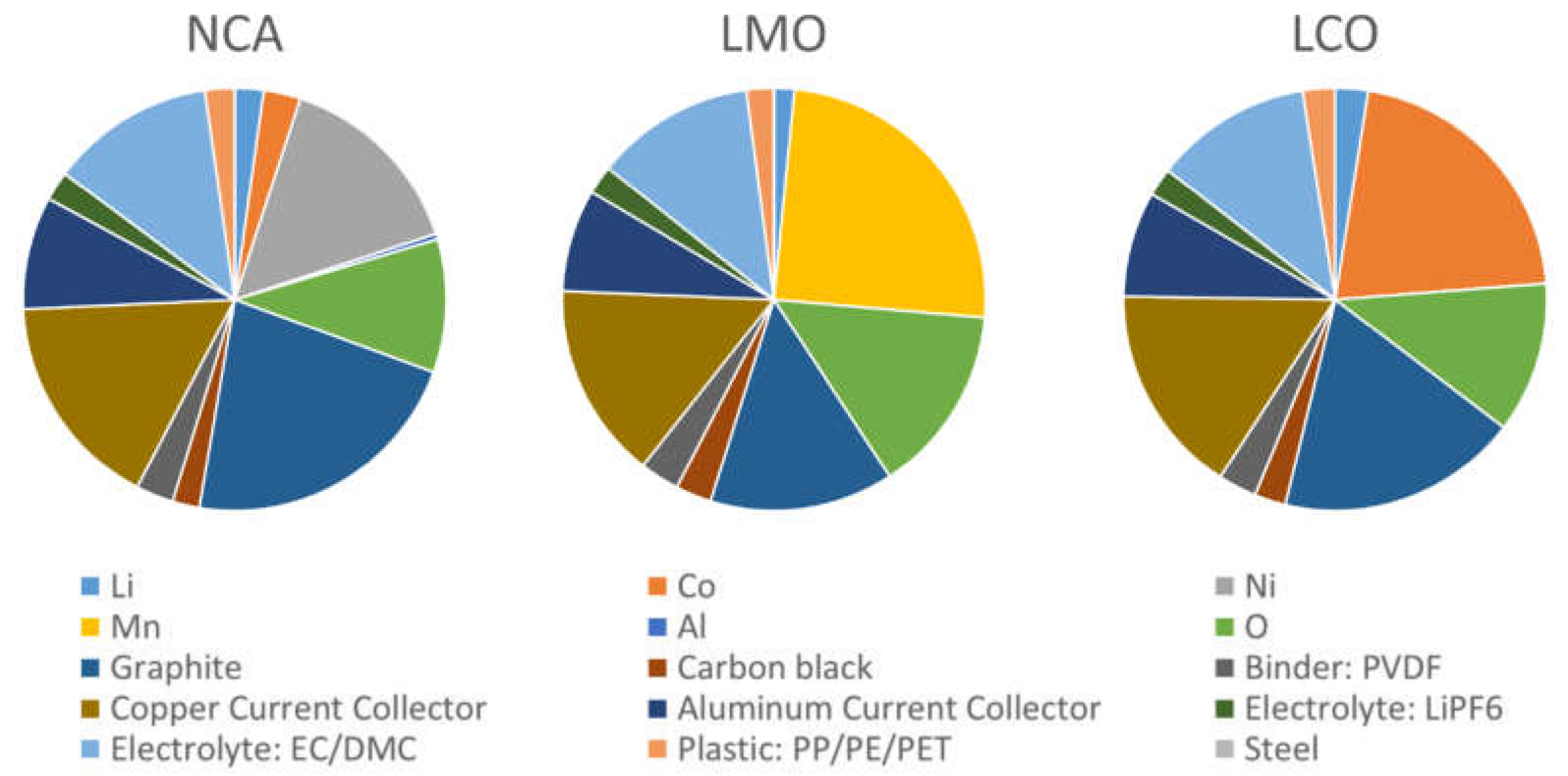
An average of the chemical cell composition is given by Mossali et al., [
24] however this was based upon an average of several cell types. We compare the several chemistries used in electric vehicle cells using BATPAC
© Argonne National Labs, IL, USA. [
25]–see
Figure 1.
One of the principal challenges in Li-ion battery recycling is the sheer complexity of the battery itself. A typical battery is enclosed in a large pack housing, within which there is a number of modules (each containing several pouch cells), circuitry and the battery management system [
30,
31]. The exact layout of each of these components is different between manufacturers. Even at the pouch cell level, each cell contains many chemical components (outer pouch material, aluminum and copper sheets, anode and cathode material) and separating these is not a trivial problem. A particular challenge is presented by the anode and cathode materials, which consist of a mixture of various chemical components and require advanced chemical and physical methods, such as such as ultrahigh shear de-agglomeration, calcination and soxhlet extraction, froth flotation, selective leaching, direct regeneration and mechanochemical recovery, to be separated into ‘pure’ materials; their constituent materials parts with no or limited contamination. [
32,
33,
34,
35,
36,
37,
38] The benefits of recycling and materials recovery are, however, substantial; in a truly circular economy, we should aim to recover and protect the critical materials contained in LIBs.
Figure 1 gives a visual representation of the materials present in three different prismatic LIB chemistries; LiCoO
2 (LCO), LiMn
2O
4 (LMO) and LiNi
0.8Co
0.15Al
0.05O
2 (NCA). In particular, it is imperative to find better ways to recover and re-use metals such as lithium and cobalt, due to the precarious nature of the global supply for these materials; over 50% of global lithium production is located in a few regions of South America [
39], while over 60% of global cobalt production is located in one country, the Democratic Republic of the Congo [
40,
41].
There are concerted ongoing efforts in both academia and industry to improve the recovery levels of these critical materials but this is hindered by the fast moving nature of the industry. Recycling rates have been slow to increase, complicated by changing battery chemistries, changes in composition of materials and the lack of focus on prior material recovery stages.
As an alternative to current systems, this paper reports on work looking at dismantling and characterization of the components produced by hand dismantling systems. In order for disassembly processes to become part of the commercial recycling procedure for LIBs, there must be a potential for them to be automated, as has been discussed in the case of ‘test’ pouch cells [
42]; we discuss how our findings can be used to identify where problems and opportunities may lie for automated disassembly of LIBs in the future, particularly in terms of the health and safety aspects of the cell opening procedures. The aim of this work was initially to produce high quality transition metal containing black mass for hydrometallurgical extraction for our project partners. However during the development of this disassembly process we also optimized the process to reclaim clean and pure materials waste streams from other components; separators, pouch material, current collectors. The composition, morphology and the change in properties are investigated for two types of different scrap cells—Quality Control (QC) Rejected and End of Life (EOL). The potential for re-use is discussed for the different components.
2. Materials and Method Development
The batteries used for this study were automotive pouch cells from a 1st-generation Nissan Leaf. The dimensions of each cell are 215 mm × 256 mm, each cell has a nominal voltage of 3.75 V. A single Nissan Leaf car contains 192 pouch cells (with 4 cells in each of 48 modules). Each pack stores an electrical energy of 24 kW.h. The cells have cathodes which are approximately 75% Lithium Manganese oxide spinel (LMO) with 25% Lithium Nickel Cobalt aluminum Oxide (NCA) on aluminum current collectors, this is similar to reported previously [
43]. The mass ratio of LMO:NCA is calculated from the Inductively coupled plasma-optical emission spectrometry (ICP-OES) data as shown in
Supplementary S1. The anode is comprised of graphite anodes on copper current collectors. The electrolyte is LiPF
6 in an organic carbonate solvent. Our process is tailored for this battery with this chemistry. Although some aspects of the procedure are general, some will have to be tailored in order to be applicable to other battery chemistries in other car models.
The teardown procedure is as described in
Figure 2. We begin with cells that have been discharged to a suitable OCV; for safety we check the voltage with a multimeter before beginning their disassembly. Then, in a fume hood we manually cut the pouch open with a ceramic scalpel; during this whole process, metallic tools are not used due to the risk of electrical discharge. When opening the cell with a scalpel, care is taken to avoid damaging personal protective equipment such as gloves. Incisions into the pouch cell are made around the edges of the cell, avoiding cutting the stack of electrodes and current collectors; this stack is then separated into individual components using tweezers. This minimizes contact between the gloves of the person carrying out the disassembly and the components that are impregnated with electrolyte. All tools are thoroughly cleaned after this procedure. We envisage that for a future automated process, the pouch incision could be made using a laser. Current investigations using laser-opening methods are ongoing; the operation of which is being optimized to reduce the heat transfer to the cell components whilst still cutting open the packaging, to ensure that thermal runaway does not occur. It is noted that the settings for a laminated aluminum pouch are different from a steel can. In addition, the laminated aluminum pouch is easily cut with a blade if necessary, whereas the steel can require greater power or energy to pierce. The pouch cell is the subject of this study. The cell components are physically separated into three groups; anode, cathode and ‘other’ materials. This physical separation minimizes the possibility of cross-contamination during further processing, this is currently by hand, however we foresee the ability to automate this process and some steps towards automatic separation have been reported [
42,
44,
45]. It is noted however that upon opening of the cells, the LiPF
6 salt in the electrolyte can hydrolyze to produce HF and end of life cells may contain lithium dendrites. Therefore, processes need to be developed such that lithium dendrites are pacified (such as with CO
2 or water mist) and gaseous HF is not released to atmosphere. To remove the electrolyte and salt from the electrode, the three components are washed in separate solvent baths of isopropan-2-ol (IPA) in a fume cupboard at ambient temperature, before drying under vacuum, (the electrolyte remains in the bath). The procedure was attempted using a number of solvents, including acetone, diethyl carbonate, dimethyl carbonate and IPA. In some of these solvents, the electrode black mass delaminated from the metal films from the cell. IPA proved to be the most effective solvent for this process because it caused the least delamination and therefore was chosen as the washing solvent. In this case, we have not separated the electrolyte any further; the carbonates remain dissolved in the IPA or water and a white lithium containing precipitate starts to form over time. The aim of washing was to eliminate the possibility of HF forming from hydrolysis of the LiPF
6 salt during the further component processing and handling. After washing, the outer part of the pouch and the separator can be recycled. Then, the electrode ‘black mass’ can be separated from the copper and aluminum foil sheets. There are several ways of liberating the materials from the current collector; thermal liberation to break down the binder, [
46,
47] solvent delamination [
21,
48], physical methods such as ultrasonic and agitation. [
49] Binder calcination forms HF due to decomposition of the PVDF and solvent delamination (in N-methyl Pyrrollidone (NMP)) produces a secondary waste which falls under current REACH regulations. [
50] In this work, our focus was upon an environmentally conscious solution for scale-up to industry and therefore we chose to investigate a combination of ultrasonic delamination in a green solvent. Initially water and DMC were used with limited delamination effect; upon the addition of an acid (2 M HNO
3) we noticed significant delamination. From previous work on copper and aluminum corrosion, it is known that the mineral acids and alkali’s will cause pitting of aluminum, particularly if the pH is below 4 or above 7 [
51]. Copper will dissolve slowly into strong acids and in aqueous solutions above pH 3 will slowly oxidize. [
52] Interestingly, previous work with oxalic acid shows a passivating effect on both aluminum [
53] and copper [
54]. We therefore chose oxalic acid, (pH 3), in water, as a greener delamination solvent alternative to NMP. Initially the oxalic acid concentration was optimized for delamination of the QC rejected cells, where we observed the least damage and maximum delamination using weak organic solutions in an ultrasonic bath. Therefore, due to delamination efficiencies and secondary waste concerns we chose to concentrate and optimize the processes using oxalic acid in this study, greater efficiency or optimization may be possible utilizing alternatives. The black mass was extracted by sonication in a bath of oxalic acid at a respective optimized concentration for the copper and aluminum delamination process. It is possible to further reclaim the black mass components; active materials, conductive additive and binder (PVDF). These components are present in very small quantities (typically <10% by weight of the black mass). Heat treatments can break down and burn off the PVDF or binder [
55], however we can only recover the active material components; graphite or the metal oxides. This process also delithiates the cathode materials [
56] and also has the disadvantage of being quite energy-intensive. In this work we show as an example for the re-use case, materials which have been heat treated in this way. If we wish to recover all materials including the PVDF binder and to do this without such aggressive heating, it is necessary to consider a route that involves solvents to strip the binder out of the anode and cathode materials. We show as an example the possibility to remove the PVDF and carbon black from the black mass using NMP as a solvent. This however is not sustainable and further work for investigations of green solvents or other removal methods are required.
3. Experimental Details
Delamination—The anodic and cathodic “black mass” was separated from the copper and aluminum sheets present in the cell. The individual components were first washed in IPA or water (as above) and then dried for 24 h at 50–75 °C and 100 mBar. This was followed by a sonication process (40 Hz, 50 W) in a solution of oxalic acid, to remove the “black mass” from the metal foils. The anodic “black mass” was separated from the copper foils in an oxalic acid bath concentration 0.02 M, for 30 min at ambient temperature; the cathodic “black mass” was separated from the aluminum foils in an oxalic acid bath at a concentration of 0.5 M, for 5 min at 50 °C. The subsequent composite black mass powders were dried under vacuum at 60 °C before further processing or re-use. The black mass materials can be deconstructed still further and the binder and conductive additives removed for example by either calcining or by chemical extraction methods, this is currently the subject of further study.
T-Peel tests were carried out on an Instron 30 kN test frame, in tension with a 500 N load cell and 1 kN wedge grips. Specimens were pre-loaded to 1.5 N to remove slack from the specimen and tested at 2 mm/min. Each specimen comprised of 2 adherends (25 mm × 120 mm) thermally bonded at one end. Specimens were bonded using the following parameters—temperature 160 °C, time 3 s, bond width 8 mm, pressure 40 kg·cm−2. SEM analysis was carried out using a Hitachi Tabletop Microscope TM3030Plus (Hitachi High-Tech Corporation, Japan). For analysis of the pouch materials, each sample was coated in AuPd, sputtered at 80 mA for 80 s under vacuum (0.01 mbar).
ICP-OES analysis—The cathodes were characterized using ICP-OES (Optima 8000, Perkin Elmer Inc., Waltham, MA, USA). Prior to analysis, the cathodes were removed from a quality control reject cell, dried at 50–75 °C and 100 mBar overnight, washed in distilled water and dried again at 50–75 °C and 100 mBar overnight. Samples were cut from the electrode sheet and dissolved in in aqua regia.
The morphological analysis of the reclaimed material was conducted with the use of Scanning Electron Microscope (SEM) (JCM-7000, JEOL, 1930 Zaventem, Belgium) equipped with a secondary electron detector and under the acceleration voltage of 15 kV. The working distances applied for the SEM study were 6.0 mm and 10.0 mm with the latter applied for the EDS analysis as well.
Electrochemical testing of the black mass—The obtained black mass was ground, sieved and subsequently utilized for the slurry preparation. The anode ink contained—reclaimed graphite, carbon black (Super C65, Timcal, Imerys, 6804 Bironica, Switzerland), carboxymethyl cellulose (Bondwell BVH8, Ashland Industries Europe GMbH, Schaffhausen, Switzerland) and styrene butadiene 40 wt. % suspension in water (Zeon Europe GmbH, 40549 Düsseldorf, Germany) in a weight ratio—92:3:2:3. The cathode coating was prepared in a dry room (dew point of −50 °C) with the following constituents—reclaimed cathode material, carbon black (Super C65), PVDF (Solef® 5130, Solvay SA, 1120 Brussels, Belgium)–prepared as 8 wt.% solution in NMP with the weight ratios of the materials—94:3:3. Both slurries were prepared with the use of centrifugal mixer (Thinky ARE 250, Intertronics, Oxfordshire, UK,) and coated onto the aluminum and copper current collectors for positive and negative electrodes, respectively. The prepared coatings were dried on a hot plate at 50 °C–anode and 80 °C–cathode. Then, they were transferred to the vacuum oven (Binder) and dried overnight at 120 °C prior to the cell assembly.
Coin cells were assembled. The electrodes and separator were cut with a TOB electrode cutter, with the disc diameter adjusted to 14.8 mm, 15.0 mm and 16.0 mm for positive electrode, negative electrode and separator (Celgard 2325, Charlotte, NC, USA) respectively. Cells were constructed with a lithium metal counter electrode and filled with 70 µL electrolyte (1 M LiPF6 in 3EC:7EMC PuriEl R&D261, Soulbrian, MI, USA). The assembled cells were tested using Bio-Logic, Seyssinet-Pariset, 38170 France, BCS cycler applying the following protocol for the anode half-cells—discharge at 0.05 C to 5 mV then charged back to 1.5 V at the same rate using constant current (CC) repeated twice. Followed by 0.2 C discharge and charge steps with the same voltage limits. The cathode half-cells were tested according to the following protocol—CC charge at 0.05 C to 4.2 V, CV step at 4.2 V and CC discharge to 2.8 V.
6. Conclusions
As discussed above, there are significant challenges inherent in the recycling of Li-ion batteries, not least of which is the variety of different chemistries in use for the cathode and anode materials. Any one approach cannot be completely general and must be adapted for the particular system being used. However, valuable insight is gained by dismantling a battery of one type and some parts of the procedure can be generalized. This is part of the hierarchy of recycling, and we have investigated the potential for re-use or remanufacturing with materials, as we further refine the waste streams. The work was originally focused upon reclamation of pure cathodic black mass waste stream for further hydrometallurgical extraction of the transition metal components, and subsequently the disassembly route developed to reclaim most of the component parts in decontaminated waste streams. We have developed a methodology with a sustainable disassembly route in mind, using sustainable solvents, low cost routes and no toxic chemicals. We also discuss the safety aspects of each process, and the methodology we have adopted to ensure chemical and electrical safety.
The principal limitation of this approach is that it is rather labor-intensive, as it requires a person to manually make incisions in the cell and separate the internal components. However, some steps of the procedure could be automated, such as the opening of the pouch in order to separate the pouch components into separate stacks. Automation of the procedure would allow this process to be scaled up. The bottle necks in the automation are in cell opening and component separation. In both of these steps consideration around the types of chemicals potentially formed during the process or with exposure to air is required. In addition, the components material composition for the equipment needs consideration to ensure no corrosion of the parts. In addition, there are many types of cells; cylindrical, pouch and prismatic which are constructed in different manners, with different materials and joining mechanisms. Intelligent designs of equipment and identification tools will be required in order to identify the different cell types and therefore knowledge upon how to dismantle them.
In this article, we have demonstrated a workable method for the safe dismantling of pouch cells and have compared differences in method for the dismantling of EoL cells and QC reject cells. This “disassembly” approach allows us to recover most of the valuable materials present in each cell and to separate them into material types with greater purity than is usually possible using conventional methods that involve shredding the battery. This approach, then, has a considerable environmental benefit, as it can allow for potential re-use of some components and recovery of others for recycling.
In terms of the materials that are usefully recovered using this process, we straightforwardly obtain a significant quantity of aluminum and copper in the form of the current collectors, polymer from the separator films and the ‘black mass’ from the electrodes. Further processing is required in order to extract useful materials from the black mass. For some of the low-concentration chemical components of the black mass, it may be uneconomic to separate them completely and a short-loop recycling process may be more appropriate; this will be the subject of a future article. The polymer separators are unsuitable for simple re-use but have the potential to be recycled to form lower-grade polymer materials.
It is apparent that not all the components can be re-used, and if they are re-used they may have life-time and contamination issues. We have demonstrated the electrochemical performance of the anodic and cathodic black mass from the reclaimed and reprocessed materials, and show that the graphite can be short loop recycled, but the reclaimed cathode requires further relithiation. This is part of the circular economy for battery materials; some components can be re-used at different points of reclamation and some require remanufacturing. The ability to produce a completely recycled cell from the reclaimed components is unrealistic at present, but it may be possible to remanufacture the component parts from the reclaimed materials to produce a recycled cell. This is a great example of the circular economy picture for lithium ion battery recycling.
Author Contributions
Conceptualization, E.K. and V.G.; methodology, D.G., R.S., B.M., J.M.; investigation, D.G., R.S., J.M., B.M.; writing-original draft preparation, J.M., E.K, R.S. writing-review and editing, D.G., R.S., B.M., V.G., E.K.; supervision, E.K. and V.G.; funding acquisition, E.K. and V.G.; project administration, E.K. and V.G. All authors have read and agreed to the published version of the manuscript.
Funding
We acknowledge funding from UKRI project “Reclamation and Re-manufacture of lithium ion batteries,” reference number 104425, and Faraday Institution ReLIB FIRG005 and FIRG006.
Acknowledgments
We would like to acknowledge the help of Marc Walker and the use of the XPS facilities at the Warwick Photoemission Facility (University of Warwick). We acknowledge Marny Bharndal (University of Warwick) for assistance with the T-Peel tests. We also acknowledge the ReLIB team at Birmingham, particularly Anton Zorin, Newcastle, and Leicester for helpful discussions and advice.
Conflicts of Interest
The authors declare no conflict of interest. The funders had no role in the design of the study; in the collection, analyses or interpretation of data; in the writing of the manuscript or in the decision to publish the results.
References
- Heelan, J.; Gratz, E.; Zheng, Z.; Wang, Q.; Chen, M.; Apelian, D.; Wang, Y. Current and Prospective Li-Ion Battery Recycling and Recovery Processes. JOM 2016, 68, 2632–2638. [Google Scholar]
- Velázquez-Martínez, O.; Valio, J.; Santasalo-Aarnio, A.; Reuter, M.; Serna-Guerrero, R. A Critical Review of Lithium-Ion Battery Recycling Processes from a Circular Economy Perspective. Batteries 2019, 5, 68. [Google Scholar] [CrossRef] [Green Version]
- Tarascon, J.M.; Armand, M. Issues and challenges facing rechargeable lithium batteries. Nature 2001, 414, 359–367. [Google Scholar]
- Harper, G.; Sommerville, R.; Kendrick, E.; Driscoll, L.; Slater, P.; Stolkin, R.; Walton, A.; Christensen, P.; Heidrich, O.; Lambert, S.; et al. Recycling lithium-ion batteries from electric vehicles. Nature 2019, 575, 75–86. [Google Scholar] [CrossRef] [Green Version]
- Waldmann, T.; Iturrondobeitia, A.; Kasper, M.; Ghanbari, N.; Aguesse, F.; Bekaert, E.; Daniel, L.; Genies, S.; Gordon, I.J.; Löble, M.W.; et al. Review—Post-mortem analysis of aged lithium-ion batteries: Disassembly methodology and physico-chemical analysis techniques. J. Electrochem. Soc. 2016, 163, A2149–A2164. [Google Scholar] [CrossRef]
- Kobayashi, Y.; Kobayashi, T.; Shono, K.; Ohno, Y.; Mita, Y.; Miyashiro, H. Decrease in Capacity in Mn-Based/Graphite Commercial Lithium-Ion Batteries. J. Electrochem. Soc. 2013, 160, A1181–A1186. [Google Scholar] [CrossRef]
- Golubkov, A.W.; Scheikl, S.; Planteu, R.; Voitic, G.; Wiltsche, H.; Stangl, C.; Fauler, G.; Thaler, A.; Hacker, V. Thermal runaway of commercial 18650 Li-ion batteries with LFP and NCA cathodes - Impact of state of charge and overcharge. RSC Adv. 2015, 5, 57171–57186. [Google Scholar] [CrossRef] [Green Version]
- Sonoc, A.; Jeswiet, J.; Soo, V.K. Opportunities to improve recycling of automotive lithium ion batteries. Procedia CIRP 2015, 29, 752–757. [Google Scholar]
- Hendricks, C.E.; Mansour, A.N.; Fuentevilla, D.A.; Waller, G.H.; Ko, J.K.; Pecht, M.G. Copper Dissolution in Overdischarged Lithium-ion Cells: X-ray Photoelectron Spectroscopy and X-ray Absorption Fine Structure Analysis. J. Electrochem. Soc. 2020, 167, 090501. [Google Scholar] [CrossRef]
- Shaw-Stewart, J.; Alvarez-Reguera, A.; Greszta, A.; Marco, J.; Masood, M.; Sommerville, R.; Kendrick, E. Aqueous solution discharge of cylindrical lithium-ion cells. Sustain. Mater. Technol. 2019, 22, e00110. [Google Scholar] [CrossRef]
- Aurbach, D.; Markovsky, B.; Rodkin, A.; Cojocaru, M.; Levi, E.; Kim, H.J. An analysis of rechargeable lithium-ion batteries after prolonged cycling. Electrochim. Acta 2002, 47, 1899–1911. [Google Scholar] [CrossRef]
- Williard, N.; Sood, B.; Osterman, M.; Pecht, M. Disassembly methodology for conducting failure analysis on lithium-ion batteries. J. Mater. Sci. Mater. Electron. 2011, 22, 1616–1630. [Google Scholar]
- Wegener, K.; Andrew, S.; Raatz, A.; Dröder, K.; Herrmann, C. Disassembly of electric vehicle batteries using the example of the Audi Q5 hybrid system. Procedia CIRP 2014, 23, 155–160. [Google Scholar]
- Wang, X.; Gaustad, G.; Babbitt, C.W. Targeting high value metals in lithium-ion battery recycling via shredding and size-based separation. Waste Manag. 2016, 51, 204–213. [Google Scholar] [CrossRef] [Green Version]
- Sloop, S.; Crandon, L.; Allen, M.; Koetje, K.; Reed, L.; Gaines, L.; Sirisaksoontorn, W.; Lerner, M. A direct recycling case study from a lithium-ion battery recall. Sustain. Mater. Technol. 2020, 25. [Google Scholar] [CrossRef]
- Diekmann, J. Ecological recycling of lithium-ion batteries from electric vehicles with focus on mechanical processes. J. Electrochem. Soc. 2017, 164, A6184–A6191. [Google Scholar]
- Smith, W.N.; Swoffer, S. Recovery of lithium ion batteries. U.S. Patent 8616475B1, 31 December 2013. [Google Scholar]
- Grützke, M.; Krüger, S.; Kraft, V.; Vortmann, B.; Rothermel, S.; Winter, M.; Nowak, S. Investigation of the Storage Behavior of Shredded Lithium-Ion Batteries from Electric Vehicles for Recycling Purposes. ChemSusChem 2015, 8, 3433–3438. [Google Scholar] [CrossRef]
- Marinos, D.; Mishra, B. An Approach to Processing of Lithium-Ion Batteries for the Zero-Waste Recovery of Materials. J. Sustain. Metall. 2015, 1, 263–274. [Google Scholar] [CrossRef]
- Wang, M.M.; Zhang, C.C.; Zhang, F.S. Recycling of spent lithium-ion battery with polyvinyl chloride by mechanochemical process. Waste Manag. 2017, 67, 232–239. [Google Scholar] [CrossRef]
- Meshram, P.; Pandey, B.D.; Mankhand, T.R. Extraction of lithium from primary and secondary sources by pre-treatment, leaching and separation: a comprehensive review. Hydrometallurgy 2014, 150, 192–208. [Google Scholar]
- Kovachev, G.; Schröttner, H.; Gstrein, G.; Aiello, L.; Hanzu, I.; Wilkening, H.M.R.; Foitzik, A.; Wellm, M.; Sinz, W.; Ellersdorfer, C. Analytical Dissection of an Automotive Li-Ion Pouch Cell. Batteries 2019, 5, 67. [Google Scholar] [CrossRef] [Green Version]
- Qian, D.; Ma, C.; More, K.L.; Meng, Y.S.; Chi, M. Advanced analytical electron microscopy for lithium-ion batteries. NPG Asia Mater. 2015, 7. [Google Scholar]
- Mossali, E.; Picone, N.; Gentilini, L.; Rodrìguez, O.; Pérez, J.M.; Colledani, M. Lithium-ion batteries towards circular economy: A literature review of opportunities and issues of recycling treatments. J. Environ. Manage. 2020, 264, 110500. [Google Scholar] [CrossRef]
- BatPaC Model Software|Argonne National Laboratory. Available online: www.anl.gov/cse/batpac-model-software (accessed on 24 November 2019).
- Study on the Review of the List of Critical Raw Materials—Critical Raw Materials Factsheets; EU Publications, European Commission: Brussels, Belgium, 2017; pp. 1–93.
- Fortier, S.M.; Nassar, N.T.; Lederer, G.W.; Brainard, J.; Gambogi, J.; McCullough, E.A. Draft Critical Mineral List—Summary of Methodology and Background Information—U.S. Geological Survey Technical Input Document in Response to Secretarial Order No. 3359; U.S. Geological Survey: Reston, VA, USA, 2018. [CrossRef] [Green Version]
- Gaines, L.; Cuenca, R. Costs of Lithium-Ion Batteries for Vehicles; U.S. Department of Energy-Office of Scientific and Technical Information: Argonne, IL, USA, 2000.
- Dai, Q.; Spangenberger, J.; Ahmed, S.; Gaines, L.; Kelly, J.C.; Wang, M. EverBatt: A Closed-loop Battery Recycling Cost and Environmental Impacts Model; Department of Energy-Office of Scientific and Technical Information: Argonne, IL, USA, 2019.
- Gaines, L. Lithium-ion battery recycling processes: research towards a sustainable course. Sustain. Mater. Technol. 2018, 17, e00068. [Google Scholar]
- Gaines, L. The future of automotive lithium-ion battery recycling: charting a sustainable course. Sustain. Mater. Technol. 2014, 1–2, 2–7. [Google Scholar]
- Zhan, R.; Payne, T.; Leftwich, T.; Perrine, K.; Pan, L. De-agglomeration of cathode composites for direct recycling of Li-ion batteries. Waste Manag. 2020, 105, 39–48. [Google Scholar] [CrossRef]
- Paulino, J.F.; Busnardo, N.G.; Afonso, J.C. Recovery of valuable elements from spent Li-batteries. J. Hazard. Mater. 2008, 150, 843–849. [Google Scholar]
- Zhan, R.; Oldenburg, Z.; Pan, L. Recovery of active cathode materials from lithium-ion batteries using froth flotation. Sustain. Mater. Technol. 2018, 17, e00062. [Google Scholar]
- Gao, W. Lithium carbonate recovery from cathode scrap of spent lithium-ion battery: a closed-loop process. Environ. Sci. Technol. 2017, 51, 1662–1669. [Google Scholar]
- Li, X.; Zhang, J.; Song, D.; Song, J.; Zhang, L. Direct regeneration of recycled cathode material mixture from scrapped LiFePO4 batteries. J. Power Sources 2017, 345, 78–84. [Google Scholar]
- Dolotko, O.; Hlova, I.Z.; Mudryk, Y.; Gupta, S.; Balema, V.P. Mechanochemical recovery of Co and Li from LCO cathode of lithium-ion battery. J. Alloys Compd. 2020, 824. [Google Scholar] [CrossRef]
- Lestriez, B. Functions of polymers in composite electrodes of lithium ion batteries. Comptes Rendus Chim. 2010, 13, 1341–1350. [Google Scholar]
- Egbue, O.; Long, S. Critical issues in the supply chain of lithium for electric vehicle batteries. EMJ-Eng. Manag. J. 2012, 24, 52–62. [Google Scholar] [CrossRef]
- Banza Lubaba Nkulu, C.; Casas, L.; Haufroid, V.; De Putter, T.; Saenen, N.D.; Kayembe-Kitenge, T.; Musa Obadia, P.; Kyanika Wa Mukoma, D.; Lunda Ilunga, J.M.; Nawrot, T.S.; et al. Sustainability of artisanal mining of cobalt in DR Congo. Nat. Sustain. 2018, 1, 495–504. [Google Scholar] [CrossRef]
- Turcheniuk, K.; Bondarev, D.; Singhal, V.; Yushin, G. Ten years left to redesign lithium-ion batteries. Nature 2018, 559, 467–470. [Google Scholar]
- Li, L.; Zheng, P.; Yang, T.; Sturges, R.; Ellis, M.W.; Li, Z. Disassembly Automation for Recycling End-of-Life Lithium-Ion Pouch Cells. JOM 2019, 71, 4457–4464. [Google Scholar] [CrossRef] [Green Version]
- Cell, Module, and Pack for EV Applications|Automotive Energy Supply Corporation. Available online: http://archive.is/h0BZL (accessed on 2 February 2020).
- Schmitt, J.; Haupt, H.; Kurrat, M.; Raatz, A. Disassembly automation for lithium-ion battery systems using a flexible gripper. In Proceedings of the IEEE 15th International Conference on Advanced Robotics: New Boundaries for Robotics, ICAR 2011, Tallin, Estonia, 20–23 June 2011; pp. 291–297. [Google Scholar]
- Herrmann, C.; Raatz, A.; Mennenga, M.; Schmitt, J.; Andrew, S. Assessment of automation potentials for the disassembly of automotive lithium ion battery systems. In Proceedings of the Leveraging Technology for a Sustainable World—Proceedings of the 19th CIRP Conference on Life Cycle Engineering, Berkeley, CA, USA, 23–25 May 2012; Springer: Berlin/Heidelberg, Germany; pp. 149–154. [Google Scholar]
- Hanisch, C.; Loellhoeffel, T.; Diekmann, J.; Markley, K.J.; Haselrieder, W.; Kwade, A. Recycling of lithium-ion batteries: A novel method to separate coating and foil of electrodes. J. Clean. Prod. 2015, 108, 301–311. [Google Scholar] [CrossRef]
- Zhang, G.; He, Y.; Feng, Y.; Wang, H.; Zhang, T.; Xie, W.; Zhu, X. Enhancement in liberation of electrode materials derived from spent lithium-ion battery by pyrolysis. J. Clean. Prod. 2018, 199, 62–68. [Google Scholar] [CrossRef]
- Xin, Y.; Guo, X.; Chen, S.; Wang, J.; Wu, F.; Xin, B. Bioleaching of valuable metals Li, Co, Ni and Mn from spent electric vehicle Li-ion batteries for the purpose of recovery. J. Clean. Prod. 2016, 116, 249–258. [Google Scholar] [CrossRef]
- Li, J.; Shi, P.; Wang, Z.; Chen, Y.; Chang, C.C. A combined recovery process of metals in spent lithium-ion batteries. Chemosphere 2009, 77, 1132–1136. [Google Scholar] [CrossRef]
- Regulation (EC) No 1907/2006 of the European Parliament and of the Council of 18 December 2006 concerning the Registration, Evaluation, Authorisation and Restriction of Chemicals (REACH), establishing a European Chemicals Agency, amending Directive 1999/45/EC and repealing Council Regulation (EEC) No 793/93 and Commission Regulation (EC) No 1488/94 as well as Council Directive 76/769/EEC and Commission Directives 91/155/EEC, 93/67/EEC, 93/105/EC and 2000/21/EC. Available online: https://www.desitek.dk/sites/default/files/media/files/DEHN-REACH-Certificate.pdf (accessed on 8 June 2020).
- Tait, W.S. Controlling corrosion of chemical processing equipment. In Handbook of Environmental Degradation Of Materials: Third Edition; Elsevier Inc., William Andrew Publishing: Norwich, NY, USA, 2018; pp. 583–600. ISBN 9780323524735. [Google Scholar]
- Feng, Y.; Siow, K.S.; Teo, W.K.; Tan, K.L.; Hsieh, A.K. Corrosion Mechanisms and Products of Copper in Aqueous Solutions at Various pH Values. Corrosion 1997, 53, 389–398. [Google Scholar] [CrossRef]
- Satyabama, P.; Rajendran, S.; Nguyen, T.A. Corrosion inhibition of aluminum by oxalate self-assembling monolayer. Anti-Corrosion Methods Mater. 2019, 66, 768–773. [Google Scholar] [CrossRef]
- Pernel, C.; Farkas, J.; Louis, D. Copper in organic acid based cleaning solutions. J. Vac. Sci. Technol. B Microelectron. Nanom. Struct. 2006, 24, 2467–2471. [Google Scholar] [CrossRef]
- Nguyen, T. Degradation of Polyfvinyl Fluoride) and Poiyfvinylidene Fluoride). J. Macromol. Sci. Part C 1985, 25, 227–275. [Google Scholar] [CrossRef]
- Diaz, F.; Wang, Y.; Moorthy, T.; Friedrich, B. Degradation Mechanism of Nickel-Cobalt-Aluminum (NCA) Cathode Material from Spent Lithium-Ion Batteries in Microwave-Assisted Pyrolysis. Metals (Basel) 2018, 8, 565. [Google Scholar] [CrossRef] [Green Version]
- Datasheet Gen2 Cell Module, Second life EV Batteries. Available online: https://www.secondlife-evbatteries.com/nissan-leaf-1670wh-module.html (accessed on 7 February 2020).
- Sahoo, R.N.; Naik, P.K.; Das, S.C. Leaching of manganese from low-grade manganese ore using oxalic acid as reductant in sulphuric acid solution. Hydrometallurgy 2001, 62, 157–163. [Google Scholar] [CrossRef]
- Gorman, S.F.; Pathan, T.S.; Kendrick, E. The ‘use-by date’ for lithium-ion battery components. Philos. Trans. R. Soc. A Math. Phys. Eng. Sci. 2019, 377, 20180299. [Google Scholar] [CrossRef] [Green Version]
- Lux, S.F.; Lucas, I.T.; Pollak, E.; Passerini, S.; Winter, M.; Kostecki, R. The mechanism of HF formation in LiPF6 based organic carbonate electrolytes. Electrochem. commun. 2012, 14, 47–50. [Google Scholar] [CrossRef] [Green Version]
- Rombach, G. Raw material supply by aluminium recycling-Efficiency evaluation and long-term availability. Acta Mater. 2013, 61, 1012–1020. [Google Scholar] [CrossRef]
Figure 1.
Percentage breakdown of components of a typical lithium ion battery (LIB) cell with different cathode materials LiNi
0.8Co
0.15Al
0.05O
2 (NCA), LiMn
2O
4 (LMO) and LiCoO
2 (LCO); identifying the key materials and critical and strategic materials [
26,
27] (values of each component given as a percentage by weight) [
28]. As calculated for a prismatic cell using a basic cell model [
29].
Figure 2.
Schematic diagram describing our procedure for the disassembly of a Li-ion battery. Steps marked in blue are our procedure steps for each stage of the cell teardown. Boxes marked in orange represent the recovered materials. Boxes marked in green represent waste materials.
Figure 3.
(a) Photograph of a module of an end of life (EoL) battery, straight after the casing is opened. (b) Photograph of the open module, showing the pouch cells inside. (c) Photograph of an individual Quality Control (QC) reject pouch cell. (d) Photograph of an open cell pouch, showing the layers of electrode materials within.
Figure 4.
Shows the quantity of material reclaimed from the teardown methodology. Values are given for both QC reject and EoL cells. The values given are averaged over 3 cells.
Figure 5.
Scanning electron microscopy (SEM) images of copper (a) and aluminum (b) current collectors obtained from the QC reject electrodes.
Figure 6.
SEM images of the reclaimed cathode black mass for (a,b) QC rejected cells and (c,d) end of life cells.
Figure 7.
SEM images of anode black mass for (a) QC rejected cell and (b) EOL cell. Both electrodes have been washed in IPA (a) is the surface of the electrode nearest the separator and (b) is towards the current collector.
Figure 8.
SEM images showing (a), (b) the anode material after being separated from the copper film (c), (d) graphite particles from the anode, after the binder is removed by dissolving in NMP (N-methyl Pyrrollidone) followed by filtration.
Figure 9.
SEM images of the inner surface of (a) a “pristine” pouch, compared to (b) and (c) a surface from a reclaimed pouch (from a QC reject cell) that has been washed and dried. It is clear that some modification of the surface has occurred.
Figure 10.
Graphs to show load vs extension curves for a number of pouch specimens. (a) Gives an example load vs extension graph for a baseline pouch compared to a reclaimed pouch. We see an initial peak load below 5 mm and then the graph appears flatter between 5–15 mm. (b) compares the average peak load, maximum load and mean load over a number of baseline and reclaimed pouches.
Figure 11.
Mass loss of the separator on washing with various solvents (DMC, NMP, IPA, oxalic acid and water).
Figure 12.
Anode and cathode coating preparation from the reclaimed material, top diagram presents anode, bottom cathode process steps: reclaimed active material, mixed slurry, electrode coating and coin cell.
Figure 13.
Formation cycle of the (a) anodes half-cells from QC reject and end of life anodes (b) and two cathode half-cells for end of life cathode after heat treatment of the reclaimed black mass.
Table 1.
Summary of tear down and reclaimed masses of cell components from a QC rejected cell and EOL.
| Cell, Components and Materials | QC Reject | EOL |
|---|
| Component Mass (g) | Component Mass (g) |
|---|
| Full Cell | 791.0(6) | 795(1) |
| Full Cell | Electrolyte | 113(20) | 120(1) |
| Electrodes | Anodes | Cu Foil | 237(2) | 74(2) | 226.67(3) | 74.6(2) |
| Anode Black Mass | 143(1) | 152(2) |
| Unrecovered Anode | 19(1) | 0.07(1) |
| Cathodes | Al Foil | 390(9) | 51(2) | 399.4(2) | 44.41(5) |
| Cathode black Mass | 310(4) | 290(1) |
| Unrecovered Cathode | 29.12 | 65.26 |
| Other | Plastics | Separator | 44.0(4) | 19.0(4) | 42 (2) | 17(1) |
| Pouch | 25.00(2) | 25.1(2) |
| Metals | Tabs | Cu Tab | 1.01(1) | 6.21(6) | 5.23(6) | 3.15(5) |
| Al Tab | 3.9(1) | 2.08(2) |
Table 2.
Metal Ratios of an untreated electrode (Data from
Table S2.1) and two electrodes treated with the ultrasonic separation technique.
| Metal Ratios | Untreated
Electrode | Ultrasonicated
QC Reject | Ultrasonicated
EOL |
|---|
| Ni:Mn | 0.30 | 0.31 | 0.30 |
| Ni:Co | 8.1 | 7.8 | 3.9 |
| Co:Mn | 0.04 | 0.04 | 0.08 |
© 2020 by the authors. Licensee MDPI, Basel, Switzerland. This article is an open access article distributed under the terms and conditions of the Creative Commons Attribution (CC BY) license (http://creativecommons.org/licenses/by/4.0/).

 ,
, 


