Formability of Medium Mn Steel Welded Joints


Abstract
:1. Introduction
2. Materials and Methods
2.1. Materials and Welding Parameters
2.2. Microstructural Characterization and Mechanical Property Test
2.3. Cupping Test FE Simulation
3. Results
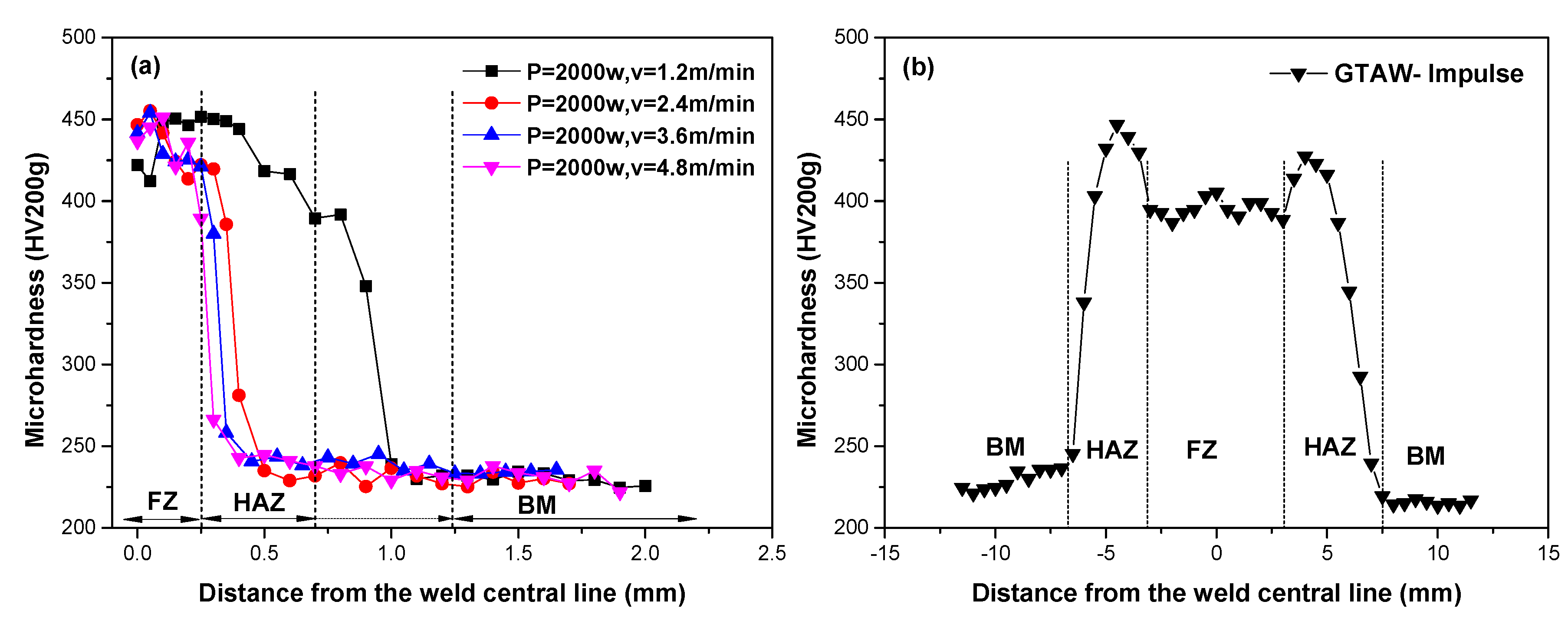
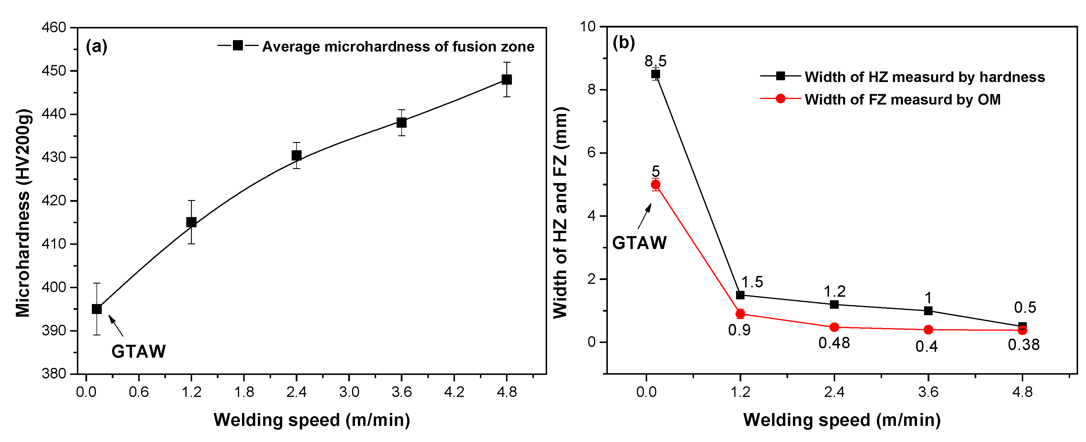
3.1. Microstructure and Microhardness
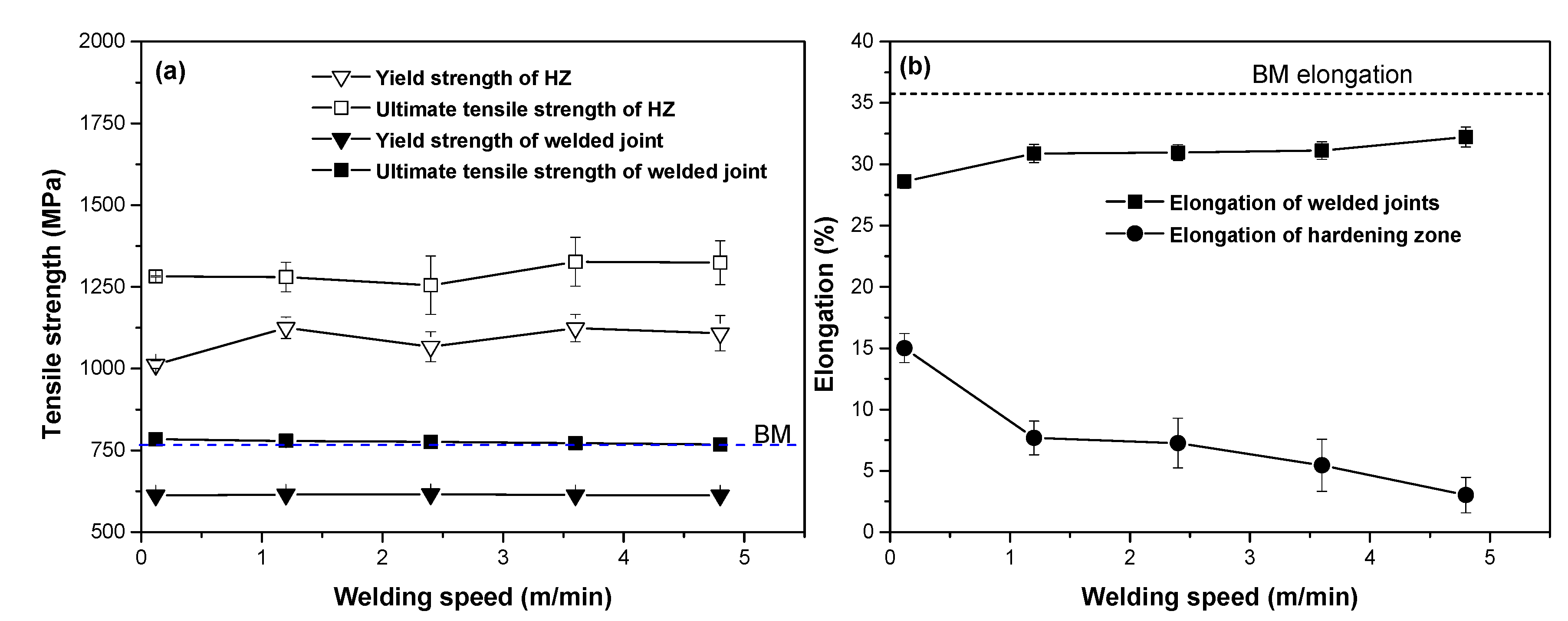
3.2. Tensile Properties
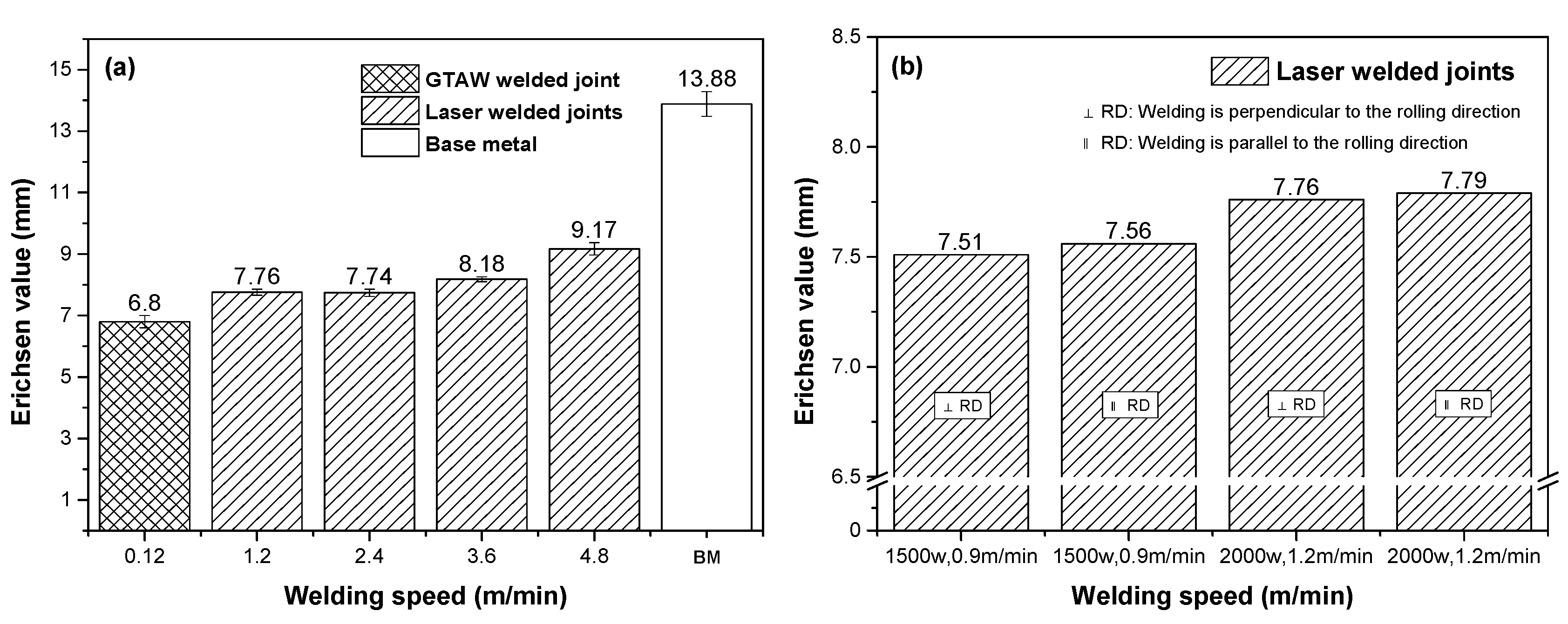
3.3. Erichsen Cupping Test
4. Discussion
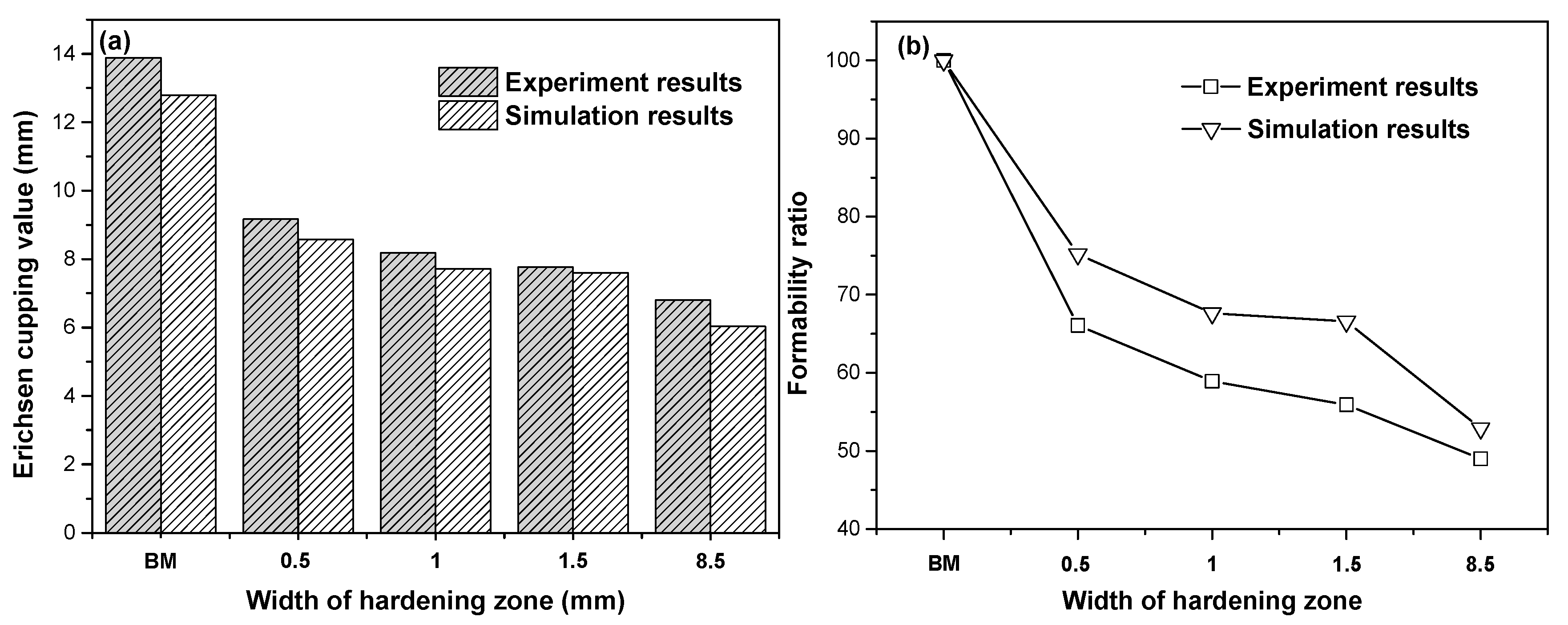
4.1. Effect of the HZ on the Formability of Welded Joints
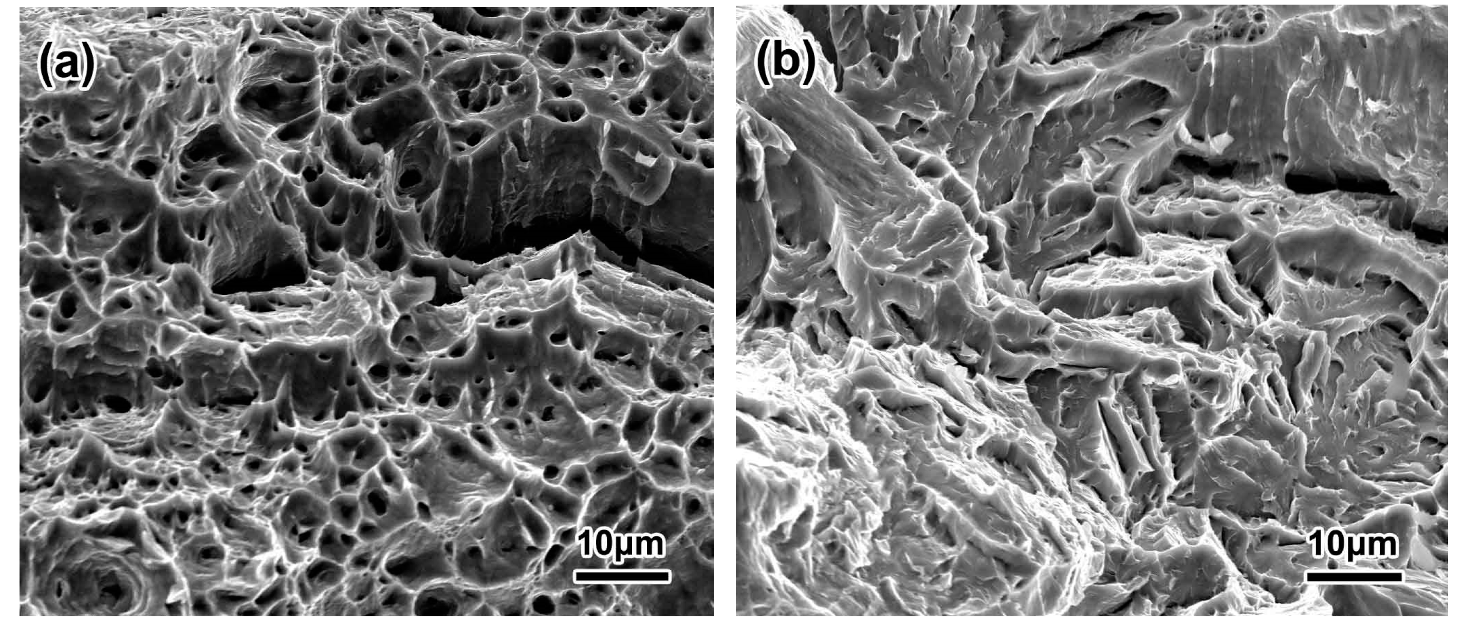
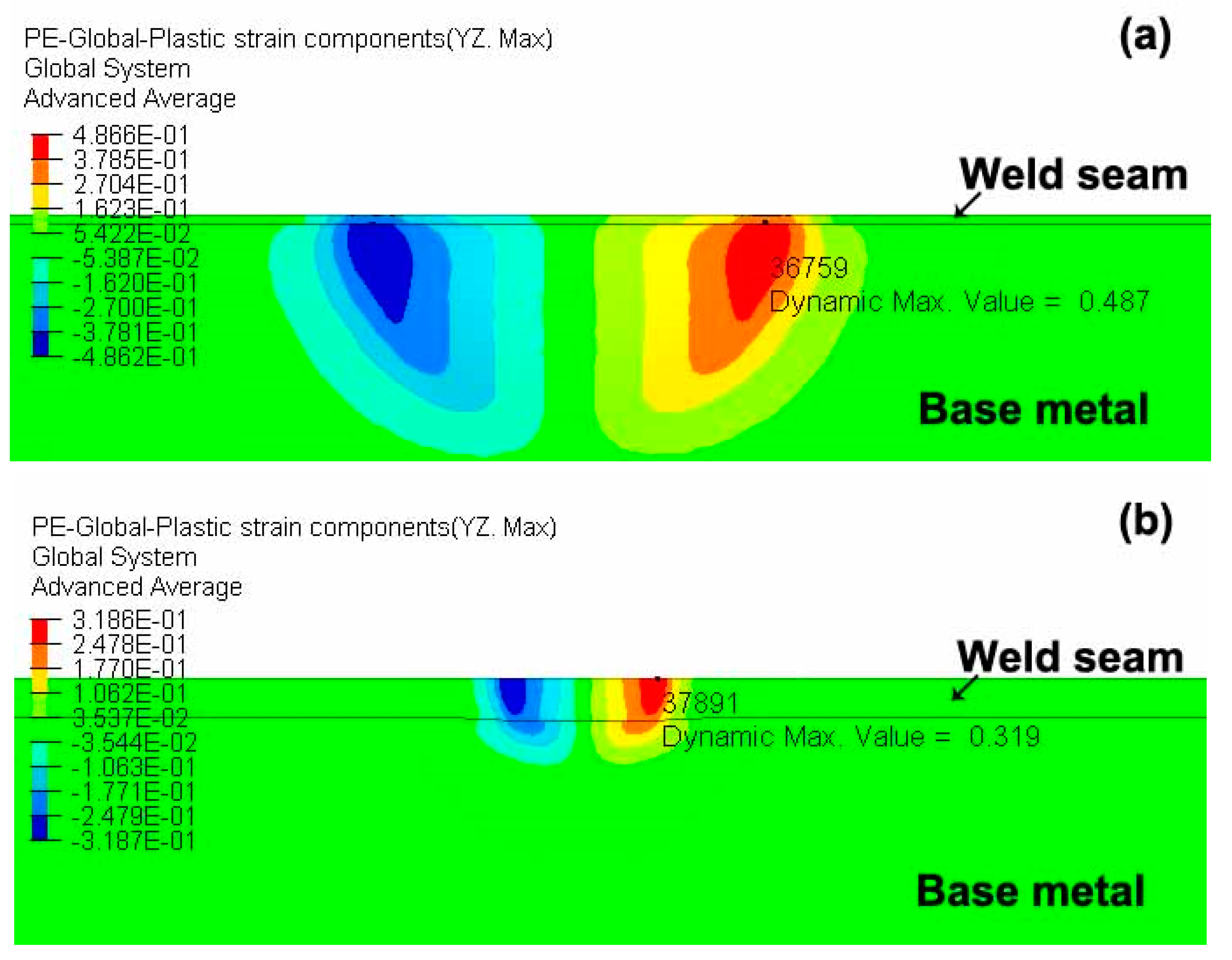
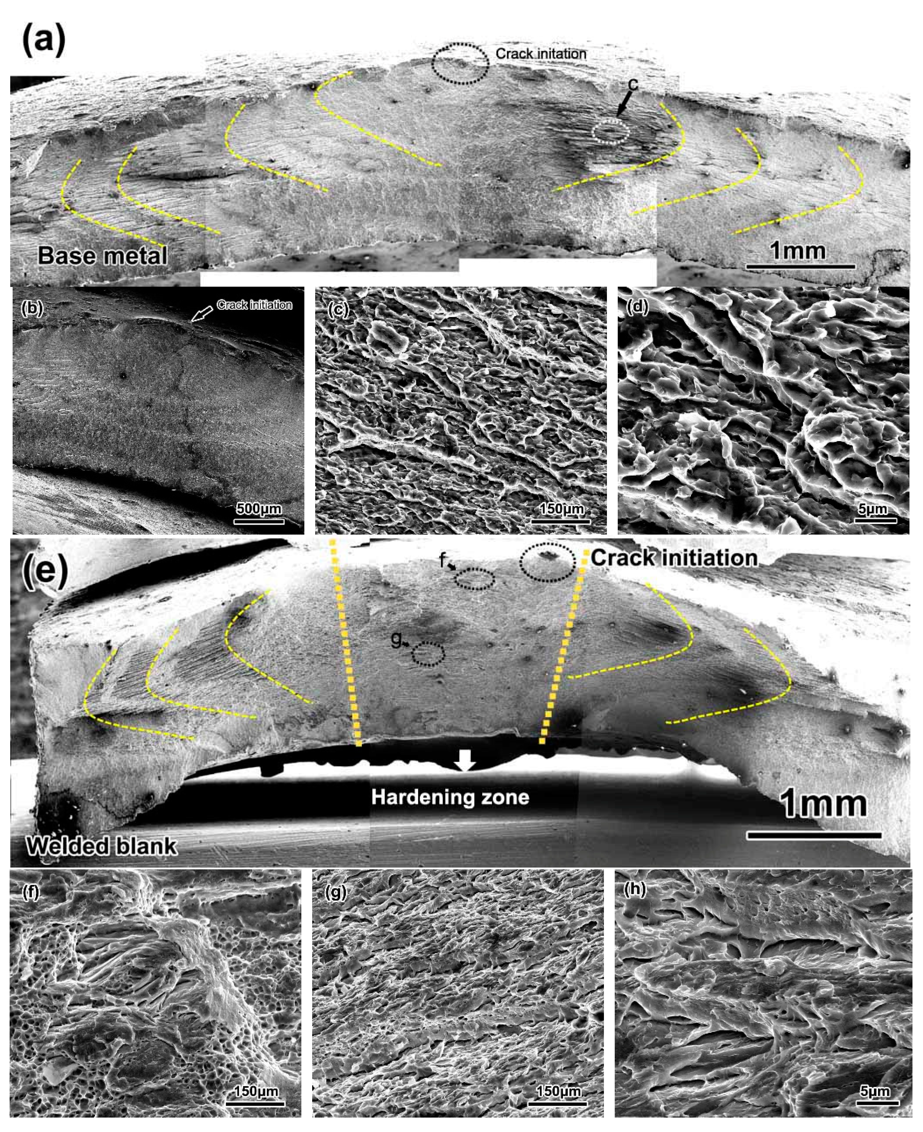
4.2. Cupping Crack Initiation and Propagation of Welded Joints
5. Conclusions
- (1)
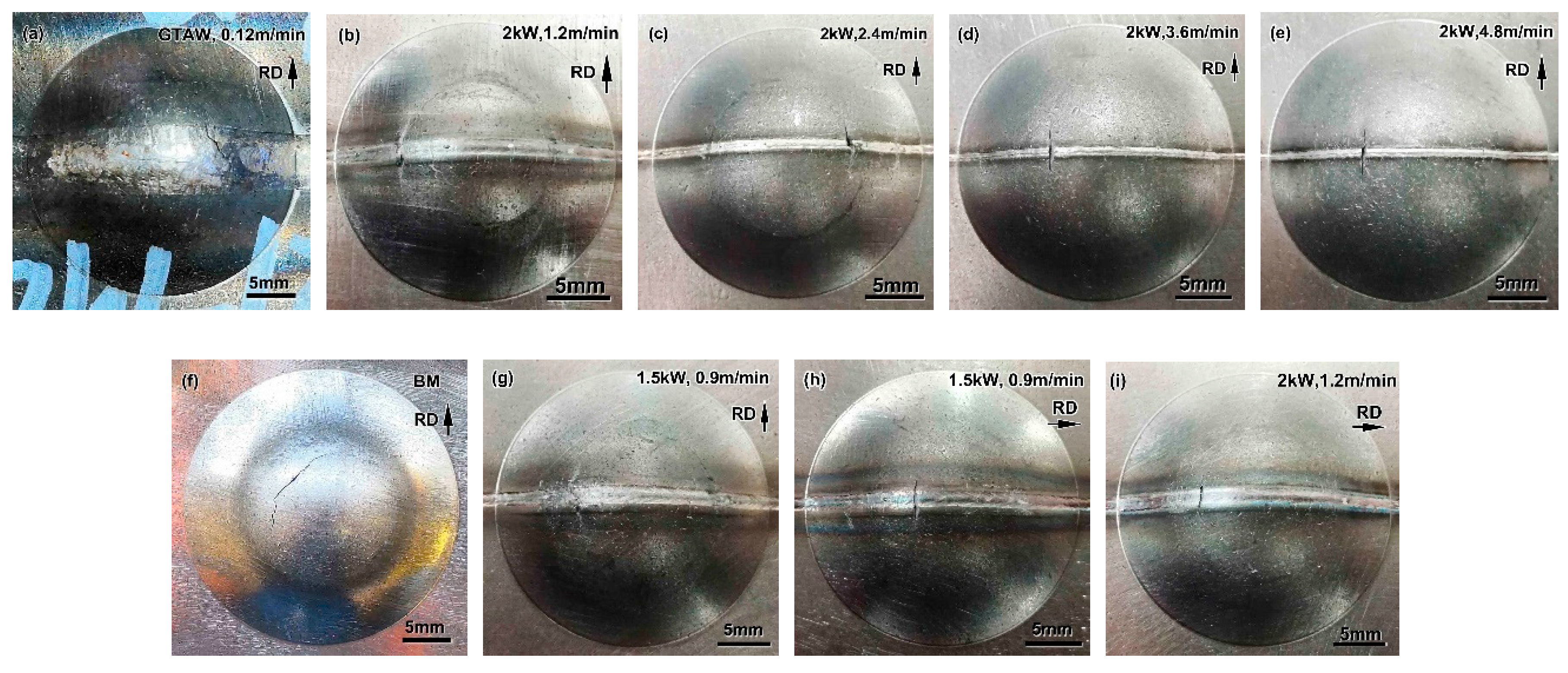
- Medium Mn steel shows good formability, which is attributed to its excellent ductility in the uniaxial tensile test. Medium Mn steel has isotropic characteristics, which result in a fracture surface with a crescent-shaped path around the center of the dome during the Erichsen cupping test.
- (2)
- Due to the existence of the HZ, the Erichsen cupping value of the welded joints is lower than that of the BM, and the formability ratio can reach 66%. The welding direction has little influence on the formability due to the isotropy of medium Mn steel.
- (3)
- The primary influencing factor on formability is the width of the HZ in welded joints, and the secondary factor is the strength and ductility of the HZ. The formability ratio of the welded joints increases due to the decrease in the width of the HZ with increasing welding speed.
- (4)
- The initiation of the Erichsen cupping crack is located in the HZ and invariably propagates perpendicular to the welding direction due to the worse ductility of the HZ.
Author Contributions
Funding
Acknowledgments
Conflicts of Interest
References
- Liu, C.; Peng, Q.; Xue, Z.; Wang, S.; Yang, C. Microstructure and Mechanical Properties of Hot- Rolled and Cold-Rolled Medium-Mn TRIP Steels. Materials 2018, 11, 2242. [Google Scholar] [CrossRef] [PubMed] [Green Version]
- Ma, Y.; Song, W.; Zhou, S.; Schwedt, A.; Bleck, W. Influence of Intercritical Annealing Temperature on Microstructure and Mechanical Properties of a Cold-Rolled Medium-Mn Steel. Metals 2018, 8, 357. [Google Scholar] [CrossRef] [Green Version]
- Podany, P.; Reardon, C.; Koukolíková, M.; Procházka, R.; Franc, A. Microstructure, Mechanical Properties and Welding of Low Carbon, Medium Manganese TWIP/TRIP Steel. Metals 2018, 8, 263. [Google Scholar] [CrossRef] [Green Version]
- Ma, Y. Medium-manganese steels processed by austenite-reverted-transformation annealing for automotive applications. Mater. Sci. Technol. 2017, 33, 1713–1727. [Google Scholar] [CrossRef]
- Wang, C.; Li, X.; Han, S.; Zhang, L.; Chang, Y.; Cao, W.; Dong, H. Warm Stamping Technology of the Medium Manganese Steel. Steel Res. Int. 2017, 89, 1700360. [Google Scholar] [CrossRef]
- Rossini, M.; Spena, P.R.; Cortese, L.; Matteis, P.; Firrao, D. Investigation on dissimilar laser welding of advanced high strength steel sheets for the automotive industry. Mater. Sci. Eng. A 2015, 628, 288–296. [Google Scholar] [CrossRef]
- Panda, S.K.; Baltazar-Hernandez, V.H.; Kuntz, M.; Zhou, Y. Formability Analysis of Diode-Laser-Welded Tailored Blanks of Advanced High-Strength Steel Sheets. Met. Mater. Trans. A 2009, 40, 1955–1967. [Google Scholar] [CrossRef]
- Sreenivasan, N.; Xia, M.; Lawson, S.; Zhou, Y. Effect of Laser Welding on Formability of DP980 steel. J. Eng. Mater. Technol. 2008, 130, 041004. [Google Scholar] [CrossRef]
- Xia, M.; Sreenivasan, N.; Lawson, S.; Zhou, Y.; Tian, Z. A Comparative Study of Formability of Diode Laser Welds in DP980 and HSLA Steels. J. Eng. Mater. Technol. 2007, 129, 446–452. [Google Scholar] [CrossRef] [Green Version]
- Panda, S.K.; Li, J.; Baltazar-Hernandez, V.H.; Zhou, Y.; Goodwin, F. Effect of Weld Location, Orientation, and Strain Path on Forming Behavior of AHSS Tailor Welded Blanks. J. Eng. Mater. Technol. 2010, 132, 041003. [Google Scholar] [CrossRef]
- Nikhare, C.P. Experimental and Numerical Investigation of Forming Limit Differences in Biaxial and Dome Test. J. Manuf. Sci. Eng. 2018, 140, 081005. [Google Scholar] [CrossRef]
- Spena, P.R.; Cortese, L.; Nalli, F.; Májlinger, K. Local formability and strength of TWIP-TRIP weldments for stamping tailor welded blanks (TWBs). Int. J. Adv. Manuf. Technol. 2018, 101, 757–771. [Google Scholar] [CrossRef]
- Xia, M.; Kuntz, M.; Tian, Z.; Zhou, Y. Failure study on laser welds of dual phase steel in formability testing. Sci. Technol. Weld. Join. 2008, 13, 378–387. [Google Scholar] [CrossRef]
- Panda, S.K.; Kuntz, M.L.; Zhou, Y. Finite element analysis of effects of soft zones on formability of laser welded advanced high strength steels. Sci. Technol. Weld. Join. 2009, 14, 52–61. [Google Scholar] [CrossRef]
- Ahmed, E.; Reisgen, U.; Schleser, M.; Mokrov, O. On formability of tailor laser welded blanks of DP/TRIP steel sheets. Sci. Technol. Weld. Join. 2010, 15, 337–342. [Google Scholar] [CrossRef]
- Peng, W.; Feng, Z.; Zheng, S. Formation quality optimization of laser hot wire cladding for repairing martensite precipitation hardening stainless steel. Opt. Laser Technol. 2015, 65, 180–188. [Google Scholar] [CrossRef]
- Wei, C.; Zhang, J.; Yang, S.; Sun, L.; Tao, W.; Wu, F.; Xia, W. Improving formability of laser welded automotive dual phase steels with local cooling. Sci. Technol. Weld. Join. 2015, 20, 145–154. [Google Scholar] [CrossRef]
- Bandyopadhyay, K.; Panda, S.K.; Saha, P. Investigations Into the Influence of Weld Zone on Formability of Fiber Laser-Welded Advanced High Strength Steel. J. Mater. Eng. Perform. 2014, 23, 1465–1479. [Google Scholar] [CrossRef]
- Bandyopadhyay, K.; Panda, S.K. Steel Processing: Formability of Steel Sheets and Tailor-Welded Blanks for Automotive Applications. Encycl. Automot. Eng. 2014, 1–26. [Google Scholar] [CrossRef]
- Cao, Y.; Luo, C.; Zhao, L.; Peng, Y.; Song, L.; Ma, C.; Tian, Z.; Zhong, M.; Wang, Y. Microstructural evolution and mechanical properties of laser-welded joints of medium manganese steel. J. Iron Steel Res. Int. 2019, 27, 75–87. [Google Scholar] [CrossRef]
- Cao, Y.; Zhao, L.; Peng, Y.; Ma, C.; Tian, Z.; Zhong, M. Effect of Heat Input on Microstructure and Mechanical Properties of Laser Welded Medium Mn Steel Joints. Chin. J. Lasers 2018, 45, 1102008. [Google Scholar] [CrossRef]
- Razmpoosh, M.; Biro, E.; Goodwin, F.; Zhou, Y. Dynamic Tensile Behavior of Fiber Laser Welds of Medium Manganese Transformation-Induced Plasticity Steel. Metall. Mater. Trans. A 2019, 50, 3578–3588. [Google Scholar] [CrossRef]
- Chang, Y.; Wang, M.; Wang, N.; Li, X.; Wang, C.; Zheng, G.; Ren, D.; Dong, H. Investigation of forming process of the third-generation automotive medium-Mn steel part with large-fractioned metastable austenite for high formability. Mater. Sci. Eng. A 2018, 721, 179–188. [Google Scholar] [CrossRef]
- Li, X.; Chang, Y.; Wang, C.; Hu, P.; Dong, H. Comparison of the hot-stamped boron-alloyed steel and the warm-stamped medium-Mn steel on microstructure and mechanical properties. Mater. Sci. Eng. A 2017, 679, 240–248. [Google Scholar] [CrossRef]
- Lun, N.; Saha, D.C.; Macwan, A.; Pan, H.; Wang, L.; Goodwin, F.; Zhou, Y. Microstructure and mechanical properties of fibre laser welded medium manganese TRIP steel. Mater. Des. 2017, 131, 450–459. [Google Scholar] [CrossRef]
- Zener, C.; Hollomon, J.H. Effect of Strain Rate Upon Plastic Flow of Steel. J. Appl. Phys. 1944, 15, 22. [Google Scholar] [CrossRef]
- Li, W.; Ma, L.; Peng, P.; Jia, Q.; Wan, Z.; Zhu, Y.; Guo, W. Microstructural evolution and deformation behavior of fiber laser welded QP980 steel joint. Mater. Sci. Eng. A 2018, 717, 124–133. [Google Scholar] [CrossRef]
- Anawa, E.M.; Olabi, A.G. Control of welding residual stress for dissimilar laser welded materials. J. Mater. Process. Technol. 2008, 204, 22–33. [Google Scholar] [CrossRef] [Green Version]
- Withers, P.J.; Bhadeshia, H. Residual stress. Part 2—Nature and origins. Mater. Sci. Technol. 2001, 17, 366–375. [Google Scholar] [CrossRef]
- Mai, T.A.; Spowage, A.C. Characterisation of dissimilar joints in laser welding of steel–kovar, copper–steel and copper–aluminium. Mater. Sci. Eng. A 2004, 374, 224–233. [Google Scholar] [CrossRef]
- Reisgen, U.; Schleser, M.; Mokrov, O.; Ahmed, E. Uni- and bi-axial deformation behavior of laser welded advanced high strength steel sheets. J. Mater. Process. Technol. 2010, 210, 2188–2196. [Google Scholar] [CrossRef]
- Elshalakany, A.B.; Ali, S.; Osman, T.A.; Megaid, H.; El Mokadem, A. An experimental investigation of the formability of low carbon steel tailor-welded blanks of different thickness ratios. Int. J. Adv. Manuf. Technol. 2016, 88, 1459–1473. [Google Scholar] [CrossRef]
- Avramovic-Cingara, G.; Saleh, C.; Jain, M.; Wilkinson, D. Void Nucleation and Growth in Dual-Phase Steel 600 during Uniaxial Tensile Testing. Met. Mater. Trans. A 2009, 40, 3117–3127. [Google Scholar] [CrossRef]


| Element | C | Mn | Si | P | S | N | Fe |
|---|---|---|---|---|---|---|---|
| wt % | 0.1 | 4.86 | 0.01 | 0.008 | 0.002 | 0.003 | Bal. |
| Welding Method | Power | Focus Length (mm) | Heat Input (J/cm) | Welding Speed (m/min) | Shielding Gas Flow (L/min) |
|---|---|---|---|---|---|
| Laser welding | 1500 | 200 | 1000 | 0.9 | 20 |
| 2000 | 200 | 1000 | 1.2 | 20 | |
| 2000 | 200 | 500 | 2.4 | 20 | |
| 2000 | 200 | 333 | 3.6 | 20 | |
| 2000 | 200 | 250 | 4.8 | 20 |
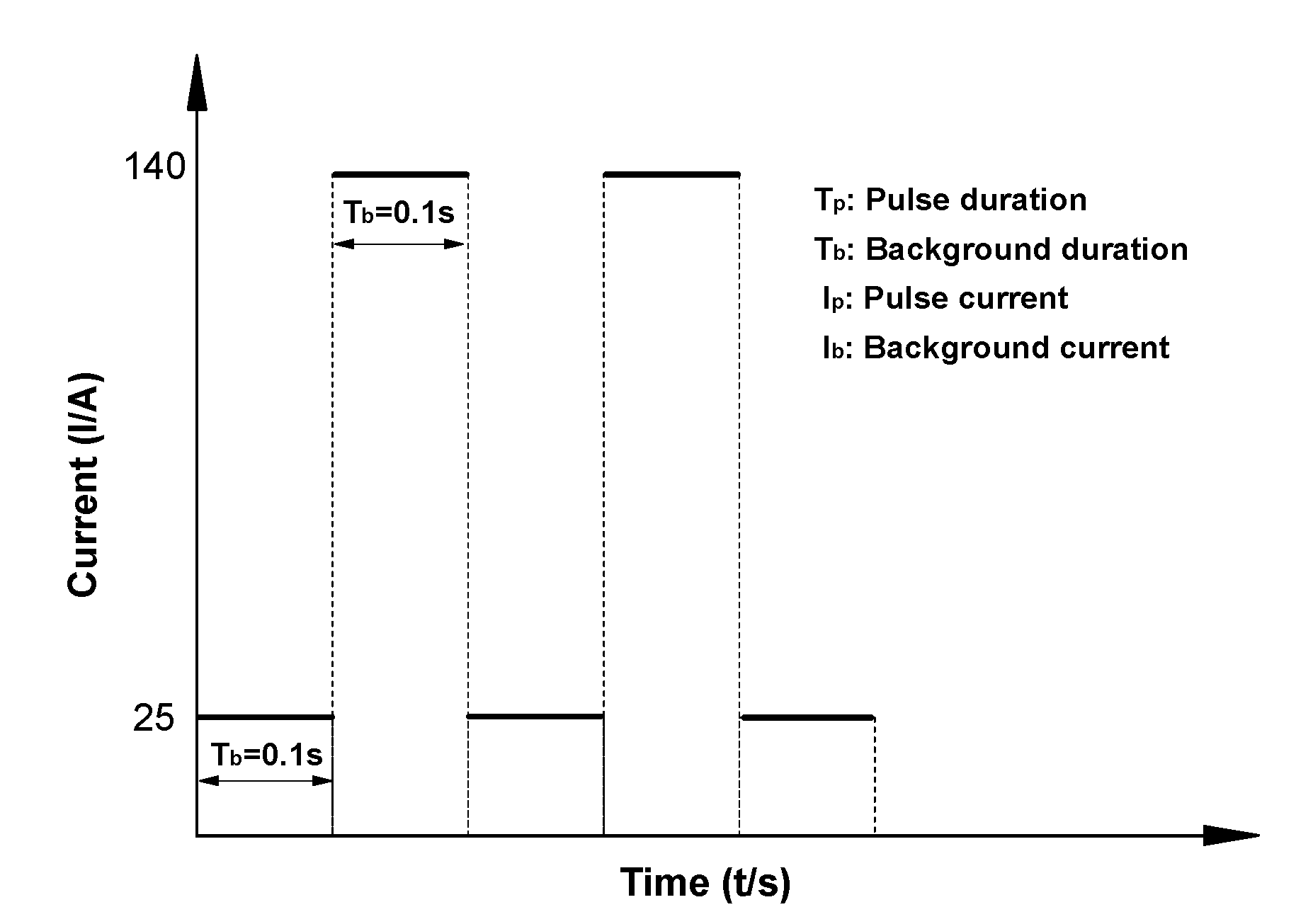
| Welding Method | Pulse Current (A) | Voltage (V) | Heat Input (J/cm) | Welding Speed (m/min) | Shielding Gas Flow (L/min) |
|---|---|---|---|---|---|
| GTAW | Ip = 140 A Tp = 0.1 s Ib = 25 A Tb = 0.1 s | 11.7 | 4826.25 | 0.12 | 20 |
© 2020 by the authors. Licensee MDPI, Basel, Switzerland. This article is an open access article distributed under the terms and conditions of the Creative Commons Attribution (CC BY) license (http://creativecommons.org/licenses/by/4.0/).
Share and Cite
Cao, Y.; Wang, B.; Zhao, L.; Peng, Y.; Zhong, M.; Zuo, H.; Tian, Z. Formability of Medium Mn Steel Welded Joints. Metals 2020, 10, 706. https://doi.org/10.3390/met10060706
Cao Y, Wang B, Zhao L, Peng Y, Zhong M, Zuo H, Tian Z. Formability of Medium Mn Steel Welded Joints. Metals. 2020; 10(6):706. https://doi.org/10.3390/met10060706
Chicago/Turabian StyleCao, Yang, Bo Wang, Lin Zhao, Yun Peng, Minlin Zhong, Hong Zuo, and Zhiling Tian. 2020. "Formability of Medium Mn Steel Welded Joints" Metals 10, no. 6: 706. https://doi.org/10.3390/met10060706