Effects of Shoulder Geometry on Microstructures and Mechanical Properties of Probeless Friction Stir Spot Welded Aluminum 7075-T651 Sheets

Abstract
:1. Introduction
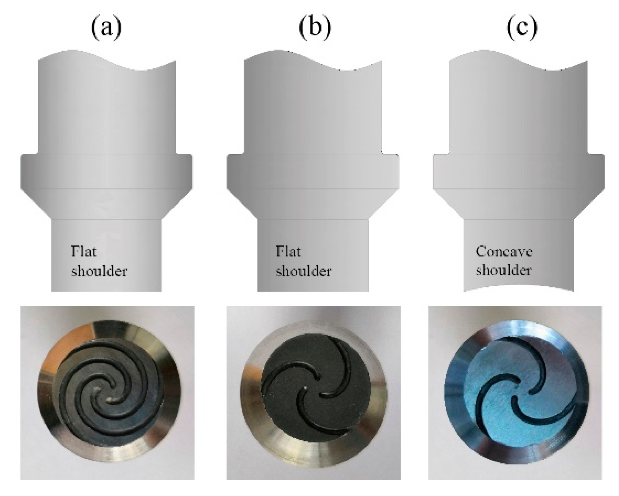
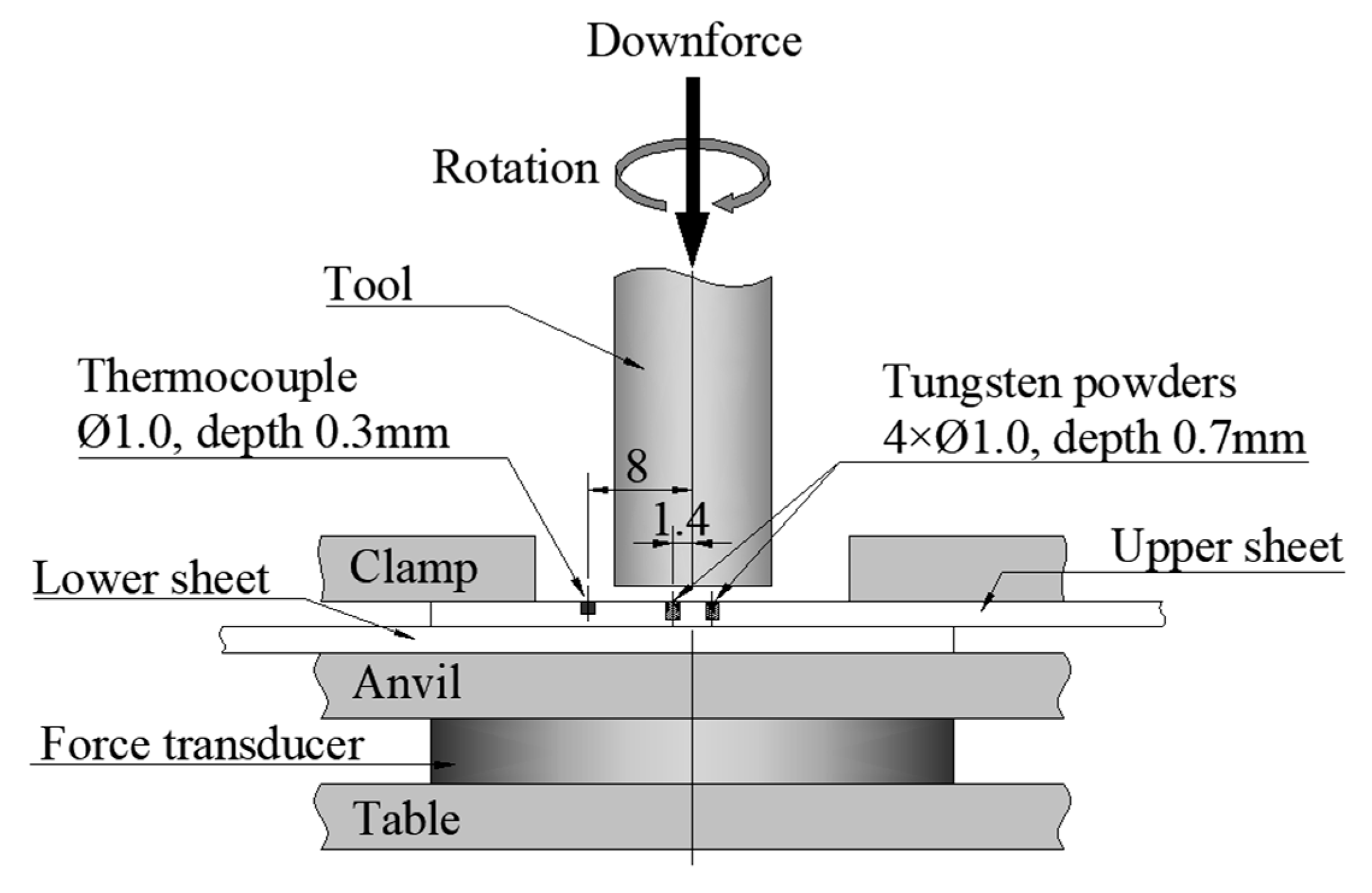
2. Experiment
3. Results and Discussions
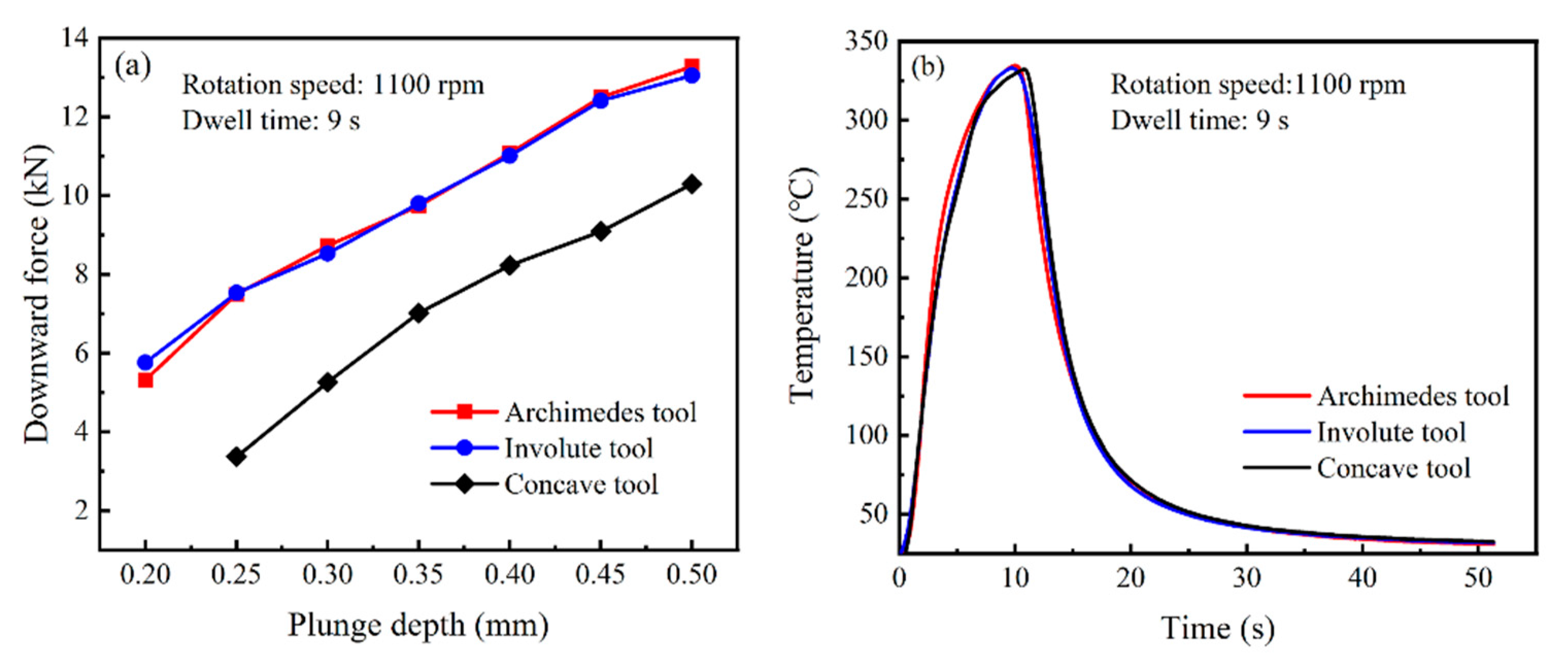
3.1. Temperature during Processing
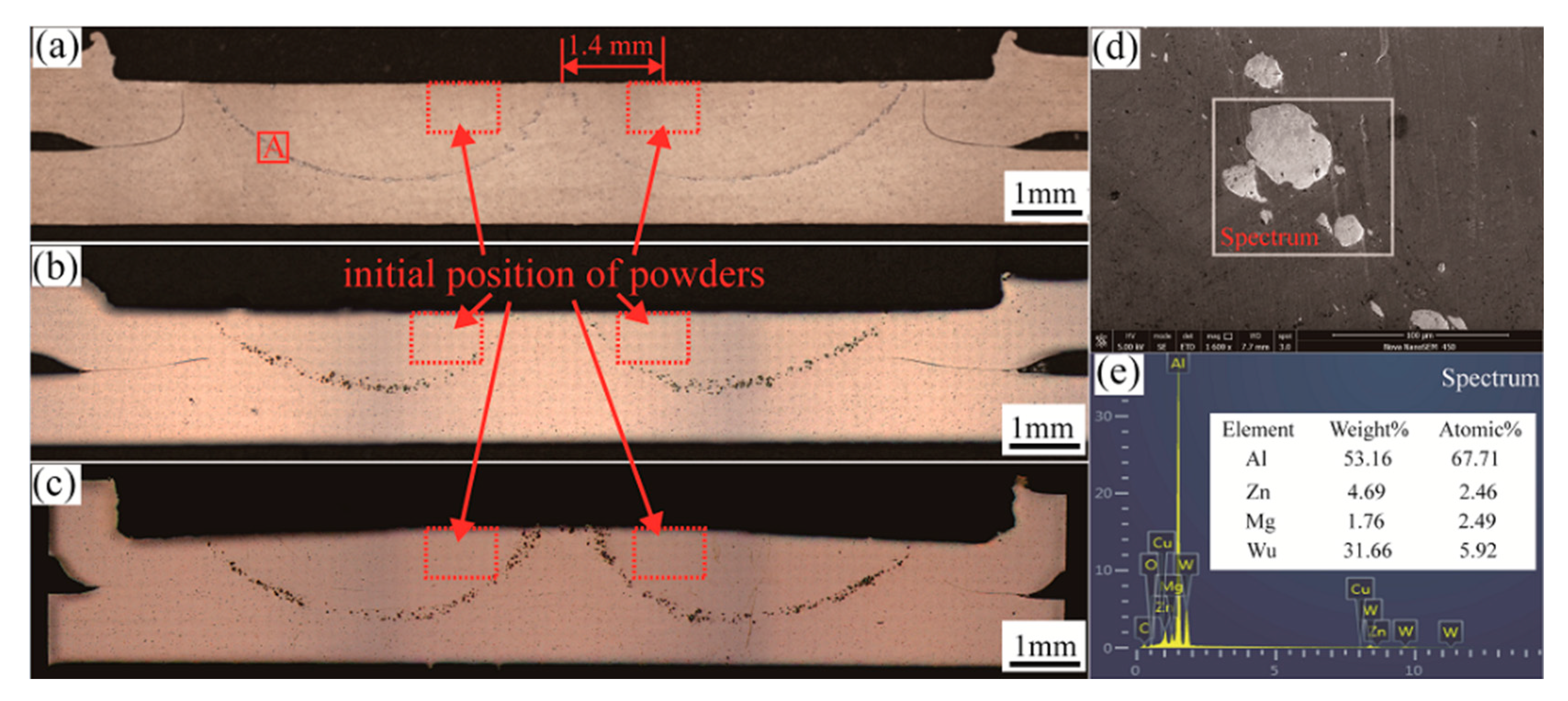
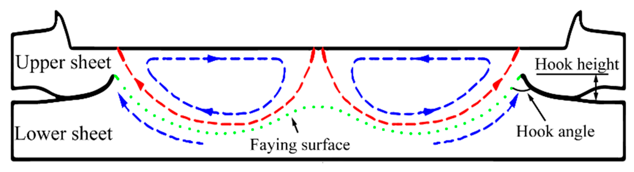
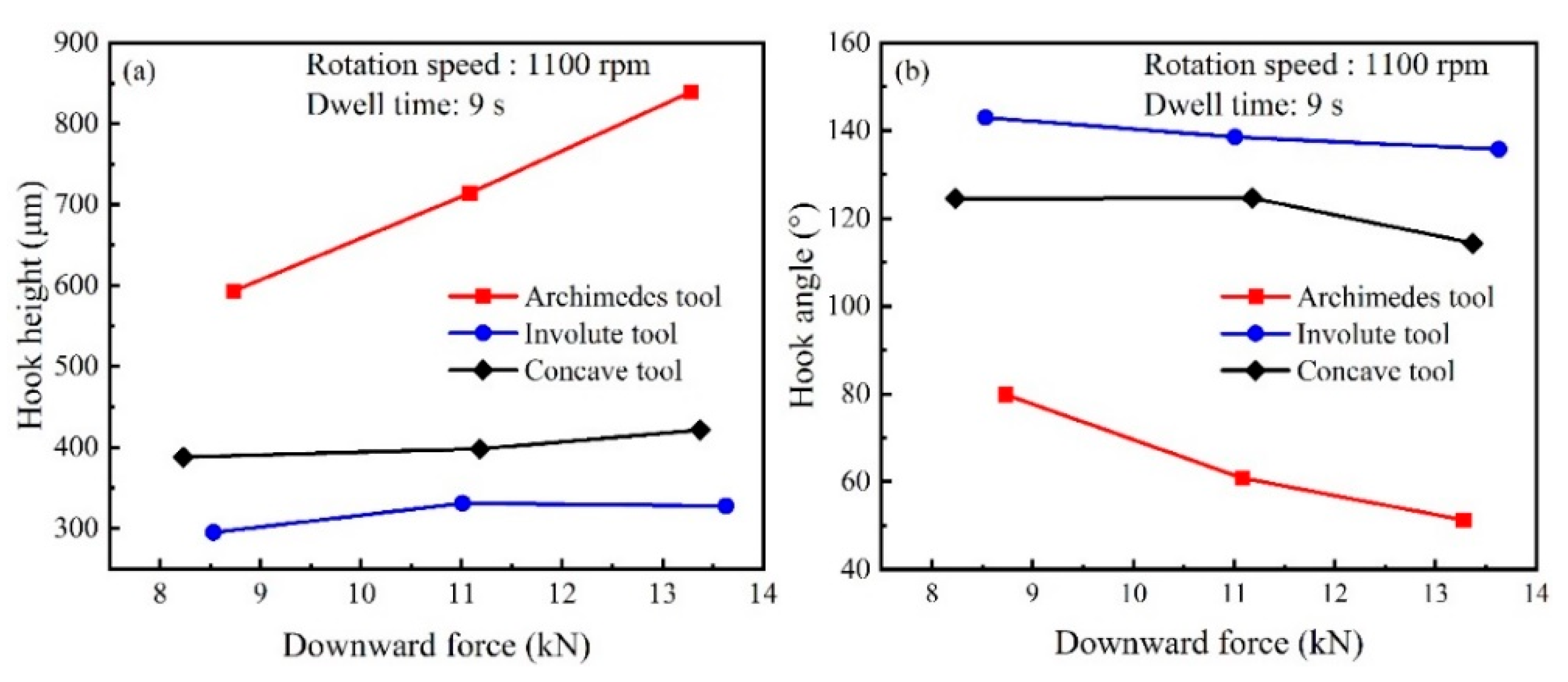
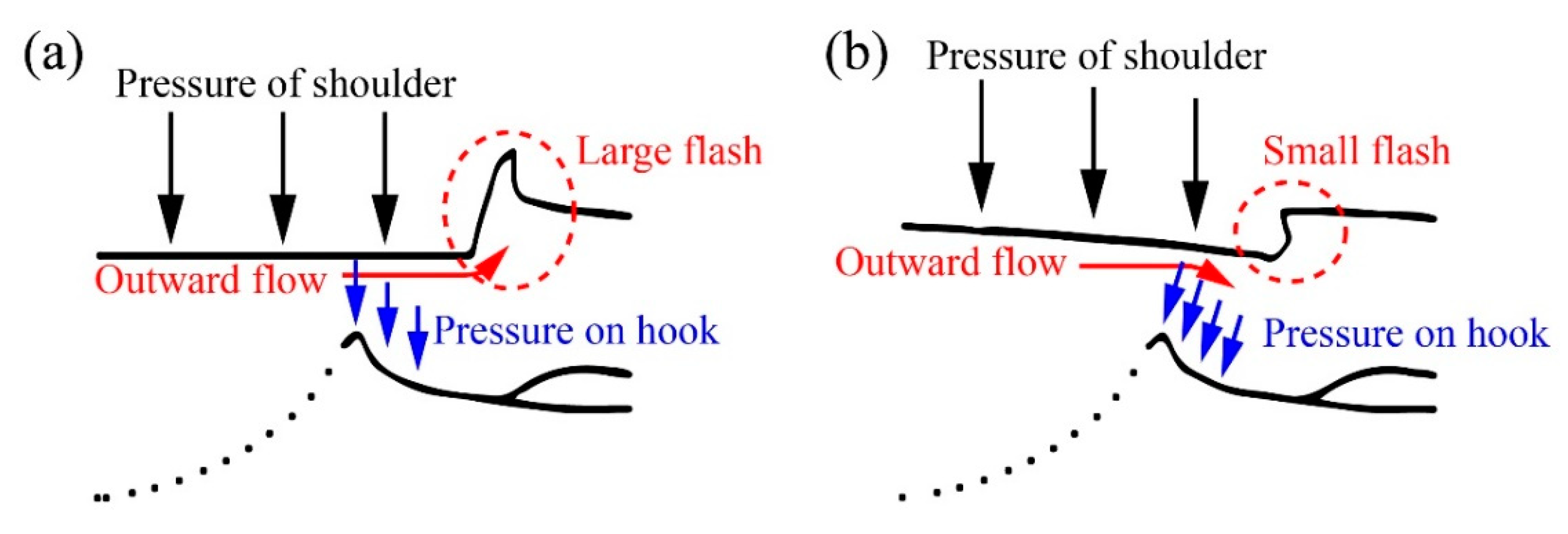
3.2. Material Flow
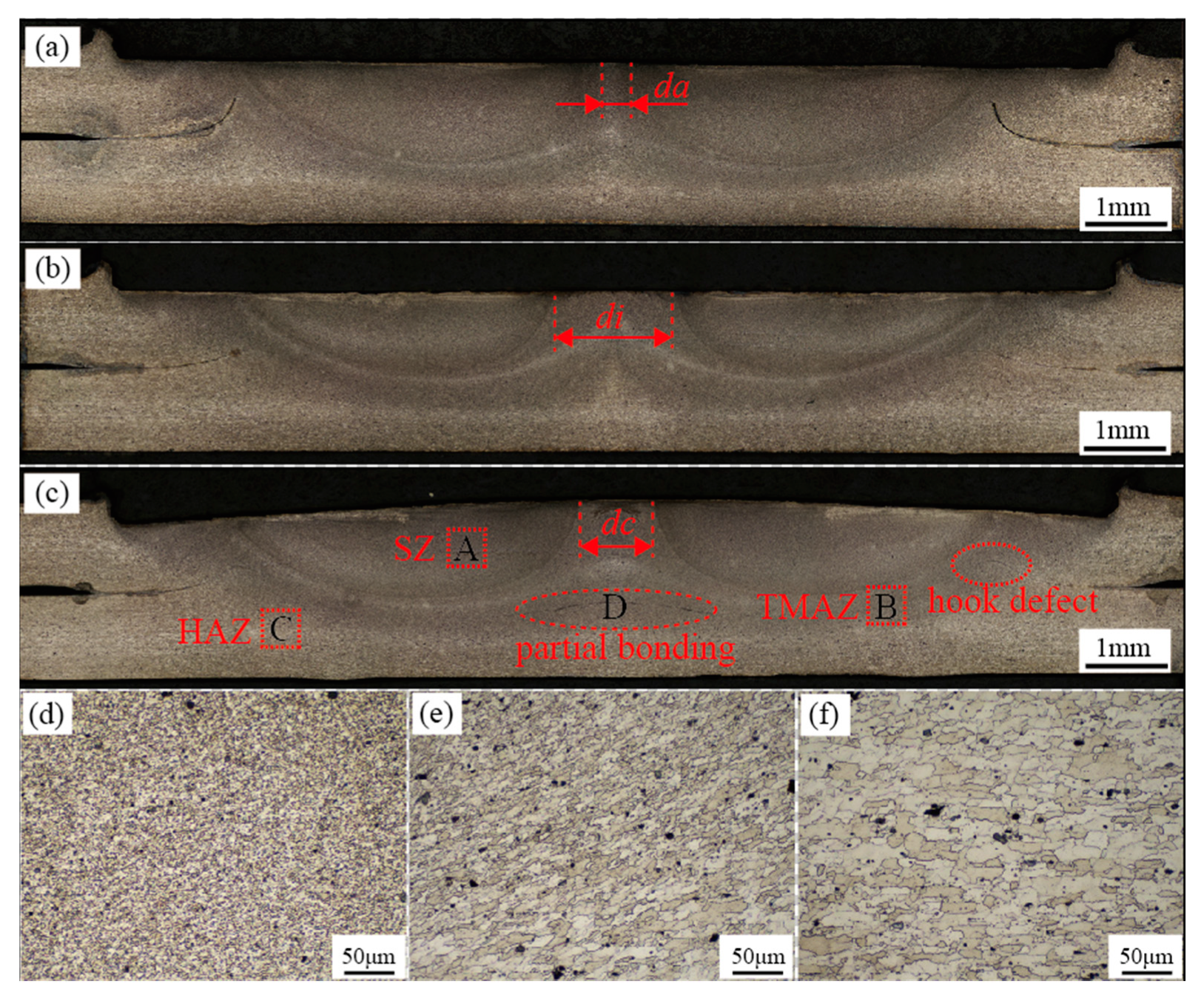
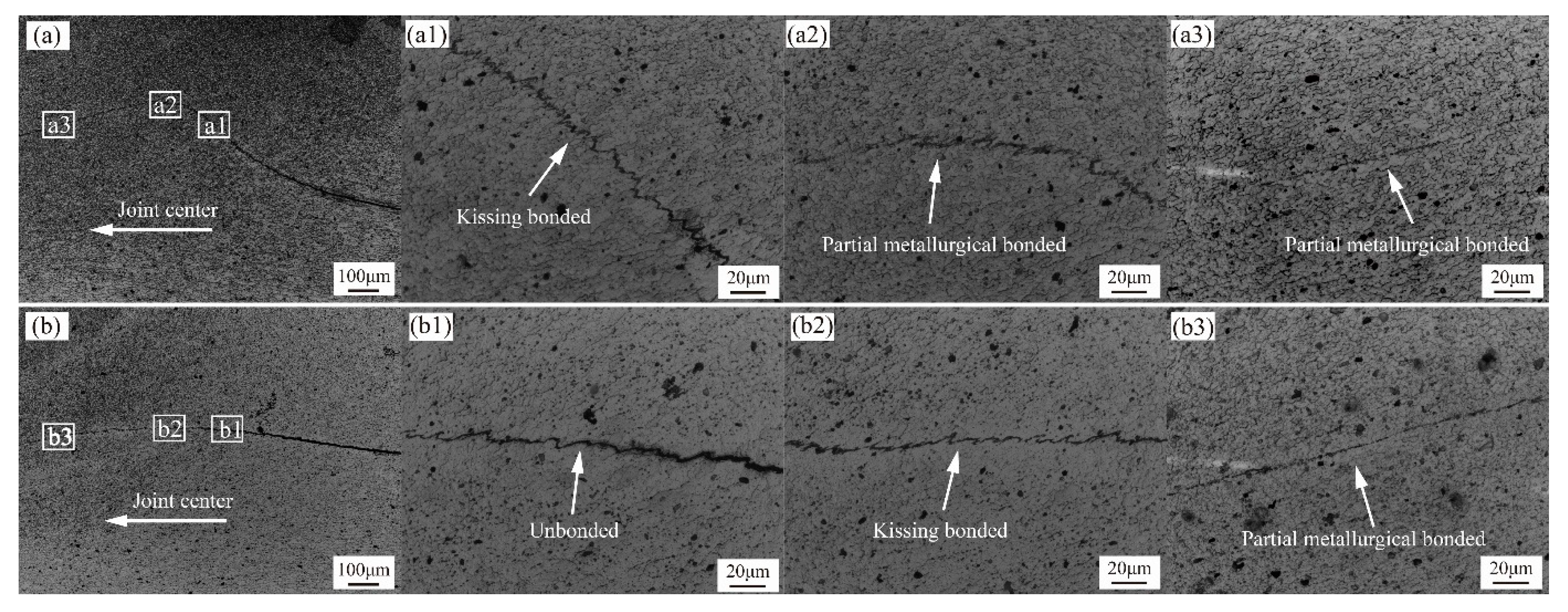
3.3. Microstructure
3.4. Mechanical Properties
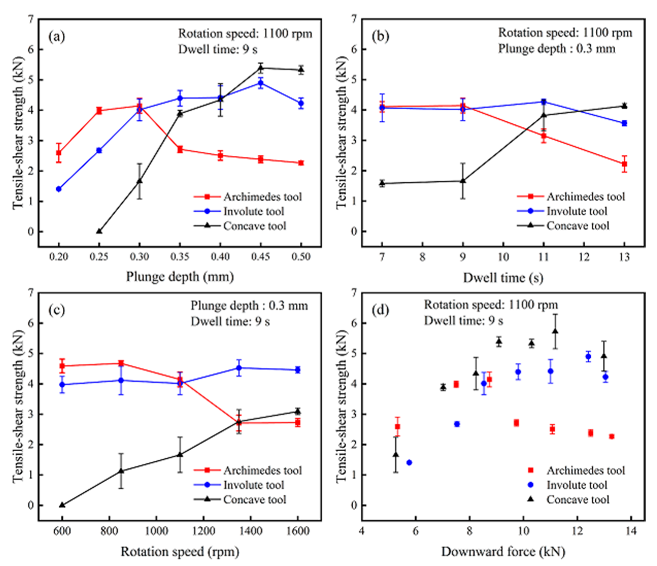
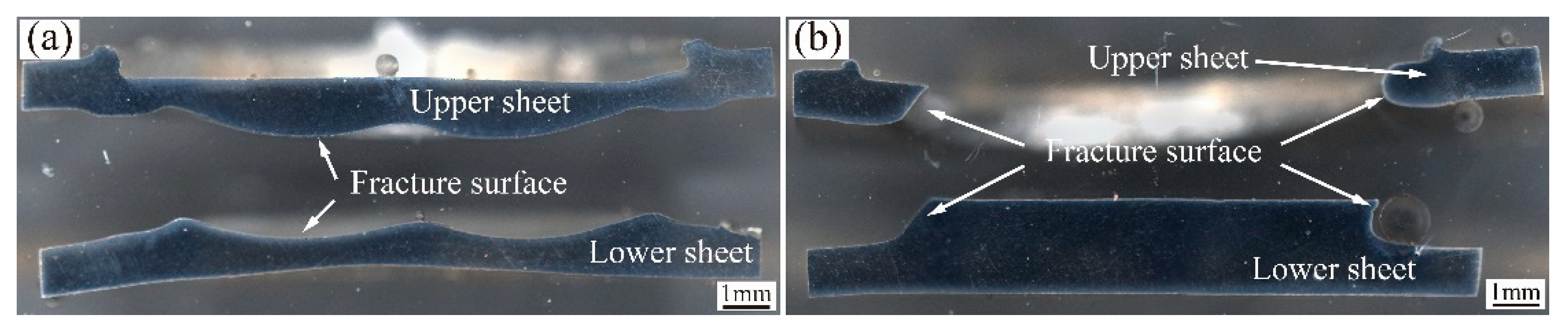
3.4.1. Tensile–Shear Testing and Fracture Mechanism
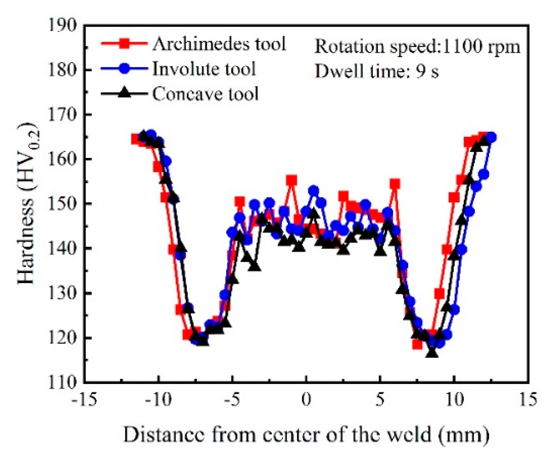
3.4.2. Microhardness
3.5. Shoulder Geometries’ Influences on Microstructures and Properties
4. Conclusions
Author Contributions
Funding
Acknowledgments
Conflicts of Interest
References
- Çevik, B. Gas tungsten arc welding of 7075 aluminum alloy: Microstructure properties, impact strength, and weld defects. Mater. Res. Express 2018, 5, 066540. [Google Scholar] [CrossRef]
- Shen, Z.; Ding, Y.; Chen, J.; Fu, L.; Liu, X.; Chen, H.; Guo, W.; Gerlich, A. Microstructure, static and fatigue properties of refill friction stir spot welded 7075-T6 aluminium alloy using a modified tool. Sci. Technol. Weld. Join. 2019, 24, 587–600. [Google Scholar] [CrossRef]
- Sadoun, A.; Wagih, A.; Fathy, A.; Essa, A. Effect of tool pin side area ratio on temperature distribution in friction stir welding. Results Phys. 2019, 15, 102814. [Google Scholar] [CrossRef]
- Deng, L.; Li, S.; Ke, L.; Liu, J.; Kang, J. Microstructure and Fracture Behavior of Refill Friction Stir Spot Welded Joints of AA2024 Using a Novel Refill Technique. Metals 2019, 9, 286. [Google Scholar] [CrossRef] [Green Version]
- Zhang, Z.; Yu, Y.; Zhao, H.; Wang, X. Interface Behavior and Impact Properties of Dissimilar Al/Steel Keyhole-Free FSSW Joints. Metals 2019, 9, 691. [Google Scholar] [CrossRef] [Green Version]
- Reimann, M.; Goebel, J.; Dos Santos, J.F. Microstructure and mechanical properties of keyhole repair welds in AA 7075-T651 using refill friction stir spot welding. Mater. Des. 2017, 132, 283–294. [Google Scholar] [CrossRef]
- Ibrahim, I.J.; Yapıcı, G.G. Application of a novel friction stir spot welding process on dissimilar aluminum joints. J. Manuf. Process. 2018, 35, 282–288. [Google Scholar] [CrossRef]
- Padhy, G.; Wu, C.; Gao, S. Friction stir based welding and processing technologies—Processes, parameters, microstructures and applications: A review. J. Mater. Sci. Technol. 2018, 34, 1–38. [Google Scholar] [CrossRef]
- Liu, J.; Song, Q.; Song, L.; Ji, S.; Li, M.; Jia, Z.; Yang, K. A Novel Friction Stir Spot Riveting of Al/Cu Dissimilar Materials. Acta Met. Sin. Engl. Lett. 2020, 1–10. [Google Scholar] [CrossRef]
- Boldsaikhan, E.; Fukada, S.; Fujimoto, M.; Kamimuki, K.; Okada, H. Refill friction stir spot welding of surface-treated aerospace aluminum alloys with faying-surface sealant. J. Manuf. Process. 2019, 42, 113–120. [Google Scholar] [CrossRef]
- Uematsu, Y.; Tokaji, K.; Tozaki, Y.; Kurita, T.; Murata, S. Effect of re-filling probe hole on tensile failure and fatigue behaviour of friction stir spot welded joints in Al–Mg–Si alloy. Int. J. Fatigue 2008, 30, 1956–1966. [Google Scholar] [CrossRef]
- Li, W.; Chu, Q.; Yang, X.; Shen, J.; Vairis, A.; Wang, W. Microstructure and morphology evolution of probeless friction stir spot welded joints of aluminum alloy. J. Mater. Process. Technol. 2018, 252, 69–80. [Google Scholar] [CrossRef]
- Bakavos, D.; Prangnell, P.B. Effect of reduced or zero pin length and anvil insulation on friction stir spot welding thin gauge 6111 automotive sheet. Sci. Technol. Weld. Join. 2009, 14, 443–456. [Google Scholar] [CrossRef]
- Bakavos, D.; Chen, Y.; Babout, L.; Prangnell, P. Material Interactions in a Novel Pinless Tool Approach to Friction Stir Spot Welding Thin Aluminum Sheet. Met. Mater. Trans. A 2010, 42, 1266–1282. [Google Scholar] [CrossRef]
- Tozaki, Y.; Uematsu, Y.; Tokaji, K. A newly developed tool without probe for friction stir spot welding and its performance. J. Mater. Process. Technol. 2010, 210, 844–851. [Google Scholar] [CrossRef]
- Chu, Q.; Li, W.; Yang, X.; Shen, J.; Vairis, A.; Feng, W.; Wang, W. Microstructure and mechanical optimization of probeless friction stir spot welded joint of an Al-Li alloy. J. Mater. Sci. Technol. 2018, 34, 1739–1746. [Google Scholar] [CrossRef]
- Li, W.; Li, J.; Zhang, Z.; Gao, D.; Wang, W.; Dong, C. Improving mechanical properties of pinless friction stir spot welded joints by eliminating hook defect. Mater. Des. 2014, 62, 247–254. [Google Scholar] [CrossRef]
- Chiou, Y.-C.; Liu, C.-T.; Lee, R.-T. A pinless embedded tool used in FSSW and FSW of aluminum alloy. J. Mater. Process. Technol. 2013, 213, 1818–1824. [Google Scholar] [CrossRef]
- Liu, Z.; Cui, H.; Ji, S.; Xu, M.; Meng, X. Improving Joint Features and Mechanical Properties of Pinless Fiction Stir Welding of Alcald 2A12-T4 Aluminum Alloy. J. Mater. Sci. Technol. 2016, 32, 1372–1377. [Google Scholar] [CrossRef]
- Xu, R.; Ni, D.; Yang, Q.; Liu, C.; Ma, Z. Pinless Friction Stir Spot Welding of Mg‒3Al‒1Zn Alloy with Zn Interlayer. J. Mater. Sci. Technol. 2016, 32, 76–88. [Google Scholar] [CrossRef]
- Yang, X.; Feng, W.; Li, W.; Xu, Y.; Chu, Q.; Ma, T.; Wang, W. Numerical modelling and experimental investigation of thermal and material flow in probeless friction stir spot welding process of Al 2198-T8. Sci. Technol. Weld. Join. 2018, 23, 704–714. [Google Scholar] [CrossRef]
- Xu, N.; Feng, R.-N.; Guo, W.-F.; Song, Q.-N.; Bao, Y.-F. Effect of Zener–Hollomon Parameter on Microstructure and Mechanical Properties of Copper Subjected to Friction Stir Welding. Acta Met. Sin. Engl. Lett. 2020, 33, 319–326. [Google Scholar] [CrossRef] [Green Version]
- Cao, J.; Wang, M.; Kong, L.; Guo, L. Hook formation and mechanical properties of friction spot welding in alloy 6061-T6. J. Mater. Process. Technol. 2016, 230, 254–262. [Google Scholar] [CrossRef]
- Liu, F.; Hovanski, Y.; Miles, M.P.; Sorensen, C.; Nelson, T. A review of friction stir welding of steels: Tool, material flow, microstructure, and properties. J. Mater. Sci. Technol. 2018, 34, 39–57. [Google Scholar] [CrossRef]
- Badarinarayan, H.; Shi, Y.; Li, X.; Okamoto, K. Effect of tool geometry on hook formation and static strength of friction stir spot welded aluminum 5754-O sheets. Int. J. Mach. Tools Manuf. 2009, 49, 814–823. [Google Scholar] [CrossRef]
- Wang, T.; Sidhar, H.; Mishra, R.S.; Hovanski, Y.; Upadhyay, P.; Carlson, B. Effect of hook characteristics on the fracture behaviour of dissimilar friction stir welded aluminium alloy and mild steel sheets. Sci. Technol. Weld. Join. 2018, 24, 178–184. [Google Scholar] [CrossRef]
- Ji, S.; Sun, X.; Ma, Z.; Gong, P.; Wen, Q. Friction stir diffusion welding realized by a novel tool with turbo-like pin. Mater. Sci. Eng. A 2020, 800, 140369. [Google Scholar] [CrossRef]
- Chen, S.; Li, X.; Jiang, X.; Yuan, T.; Hu, Y. The effect of microstructure on the mechanical properties of friction stir welded 5A06 Al Alloy. Mater. Sci. Eng. A 2018, 735, 382–393. [Google Scholar] [CrossRef]
- Sato, Y.S.; Urata, M.; Kokawa, H.; Ikeda, K. Hall–Petch relationship in friction stir welds of equal channel angular-pressed aluminium alloys. Mater. Sci. Eng. A 2003, 354, 298–305. [Google Scholar] [CrossRef]
- Mahoney, M.W.; Rhodes, C.G.; Flintoff, J.G.; Bingel, W.H.; Spurling, R.A. Properties of friction-stir-welded 7075 T651 aluminum. Met. Mater. Trans. A 1998, 29, 1955–1964. [Google Scholar] [CrossRef]
- Gemme, F.; Verreman, Y.; Dubourg, L.; Wanjara, P. Effect of welding parameters on microstructure and mechanical properties of AA7075-T6 friction stir welded joints. Fatigue Fract. Eng. Mater. Struct. 2011, 34, 877–886. [Google Scholar] [CrossRef]
- Shen, Z.; Yang, X.; Zhang, Z.; Cui, L.; Li, T. Microstructure and failure mechanisms of refill friction stir spot welded 7075-T6 aluminum alloy joints. Mater. Des. 2013, 44, 476–486. [Google Scholar] [CrossRef]
- Gerlich, A.; Avramovic-Cingara, G.; North, T.H. Stir zone microstructure and strain rate during Al 7075-T6 friction stir spot welding. Met. Mater. Trans. A 2006, 37, 2773–2786. [Google Scholar] [CrossRef]
- Chu, Q.; Yang, X.; Li, W.-Y.; Lu, T.; Zhang, Y.; Vairis, A.; Wang, W. Impact of surface state in probeless friction stir spot welding of an Al–Li alloy. Sci. Technol. Weld. Join. 2019, 24, 200–208. [Google Scholar] [CrossRef]
- Badarinarayan, H.; Yang, Q.; Zhu, S. Effect of tool geometry on static strength of friction stir spot-welded aluminum alloy. Int. J. Mach. Tools Manuf. 2009, 49, 142–148. [Google Scholar] [CrossRef]


| Alloy | Zn | Mg | Cu | Fe | Cr | Mn | Si | Ti | Al |
|---|---|---|---|---|---|---|---|---|---|
| 7075-T651 | 5.7 | 2.6 | 1.6 | 0.33 | 0.24 | 0.1 | 0.05 | 0.03 | Bal. |
| Rotation Speed (rpm) | 600, 850, 1100, 1350, 1600 |
|---|---|
| Plunge depth (mm) | 0.2, 0.25, 0.3, 0.35, 0.4, 0.45, 0.5 |
| Dwell time (s) | 7, 9, 11, 13 |
| Plunge rate (mm/min) | 20 |
| Fracture Mode | Parameters | Fractograph |
|---|---|---|
| Shear fracture | Archimede, RS = 1100, DT = 9, PD = 0.3 |  |
| Shear fracture | Involute, RS = 1100, DT = 9, PD = 0.4 |  |
| Shear fracture | Concave, RS = 1100, DT = 9, PD = 0.4 |  |
| Plug fracture | Archimedes, RS = 1100, DT = 9, PD = 0.4 |  |
Publisher’s Note: MDPI stays neutral with regard to jurisdictional claims in published maps and institutional affiliations. |
© 2020 by the authors. Licensee MDPI, Basel, Switzerland. This article is an open access article distributed under the terms and conditions of the Creative Commons Attribution (CC BY) license (http://creativecommons.org/licenses/by/4.0/).
Share and Cite
Chu, X.; Yin, M.; Gao, J.; Wang, X.; Wang, Y. Effects of Shoulder Geometry on Microstructures and Mechanical Properties of Probeless Friction Stir Spot Welded Aluminum 7075-T651 Sheets. Metals 2020, 10, 1605. https://doi.org/10.3390/met10121605
Chu X, Yin M, Gao J, Wang X, Wang Y. Effects of Shoulder Geometry on Microstructures and Mechanical Properties of Probeless Friction Stir Spot Welded Aluminum 7075-T651 Sheets. Metals. 2020; 10(12):1605. https://doi.org/10.3390/met10121605
Chicago/Turabian StyleChu, Xingrong, Meng Yin, Jun Gao, Xiaowei Wang, and Yangang Wang. 2020. "Effects of Shoulder Geometry on Microstructures and Mechanical Properties of Probeless Friction Stir Spot Welded Aluminum 7075-T651 Sheets" Metals 10, no. 12: 1605. https://doi.org/10.3390/met10121605