Article

Improvement in the Hard Milling of AISI D2 Steel under the MQCL Condition Using Emulsion-Dispersed MoS2 Nanosheets

1
Department of Manufacturing Engineering, Faculty of Mechanical Engineering, Thai Nguyen University of Technology, Thai Nguyen 250000, Vietnam
2
Faculty of Basic Sciences, College of Medicine and Pharmacy, Thai Nguyen University, Thai Nguyen 250000, Vietnam
3
Faculty of Fundamental of Sciences, Thai Nguyen University of Technology, Thai Nguyen 250000, Vietnam
*
Author to whom correspondence should be addressed.
Lubricants 2020, 8(6), 62; https://doi.org/10.3390/lubricants8060062
Submission received: 9 May 2020 / Revised: 26 May 2020 / Accepted: 1 June 2020 / Published: 5 June 2020
(This article belongs to the Special Issue Tribology of Smart Materials)

Abstract

:
The present work shows the process for MoS2 nanosheet production by liquid N2-queched bulk, a novel method having highly efficient, green, and facile operation. The produced MoS2 nanoparticles are suspended in minimum quantity cooling lubrication (MQCL)-based fluid to form nanofluid used for the hard milling of AISI D2 steel. The study aims to improve the hard-milling performance assisted by the MQCL technique using MoS2 nanofluid. ANOVA analysis is used to evaluate the effects of three input machining variables, including nanoparticle concentration, cutting speed, and material hardness on cutting forces. The results indicate that the better cooling effect from the principle of the Ranque–Hilsch vortex tube of the MQCL device combined with the better lubricating performance from MoS2 nanofluid brings out the sustainable alternative solution for machining difficult-to-cut material. Moreover, the experimental results provide the technical guides for the selection of proper values of nanoparticle concentration and cutting speed while ensuring the technological, economic, and environmental characteristics.

Graphical Abstract

1. Introduction

In the machining field, the manufacture of difficult-to-cut materials, especially hardened steel, has been growing concern not only for researchers but also for manufacturers around the world. Hardened steels have been widely used in different applications, such as mold and die, automotive components, bearings, and so on. They possess high hardness and strength properties, which makes them difficult to cut by using the conventional machining processes like turning, milling, and drilling due to large cutting forces, high cutting temperature, and severe tool wear. Traditionally, grinding operations have been the most common in machining hardened steel components (45–65 HRC). However, the low productivity, high cost, and environmental issues caused by cutting fluids are considered the main drawbacks of the grinding process [1]. Accordingly, the hard machining processes, such as hard turning, milling and drilling, have been developed to meet the growing demand of high productivity, good surface quality, coolant elimination, manufacturing cost reduction, and flexibility to different types of parts [2]. Hard turning was early recognized and applied in the automotive industry, which proved the effectiveness in technological, economic, and environmental characteristics in machining the transmission components when compared to grinding. In addition, a typical example of early applications of hard turning is the surface of gear-wheel bearings by using polycrystalline cubic boron nitride (CBN) inserts. Nevertheless, the enormous cutting heat and large cutting forces are always the main problems when applying hard machining processes, which require the high-graded inserts like coated cemented carbide, ceramics, (Polycrystalline) Cubic Boron Nitride ((P)CBN), Polycrystalline Diamond (PCD) tools [3,4,5,6]. Furthermore, dry hard cutting is often used to avoid thermal shock leading to tool failure and retain the environmentally friendly character. This also limits the range of cutting conditions and the productivity as well as the increase of manufacturing cost. Therefore, the alternative solutions have been studied and proposed to improve the cutting performance of hard machining processes, including non-traditional cutting processes assisted in machining, such as laser-assisted machining (LAM) [7,8], minimum quantity lubrication (MQL) and minimum quantity cooling lubrication (MQCL) assisted in machining and nanofluids enriched in MQL and MQCL-assisted machining [9,10,11,12,13,14,15,16,17]. Among these novel approaches, the utilization of nano additives suspended in MQL- and MQCL-based fluids was proven the significant improvement in hard cutting performance. B. Li and his co-authors (2017) [18] investigated the performance of the heat transfer of different types of nanoparticles (MoS2, ZrO2, CNT, PCD, Al2O3, SiO2) enriched in MQL-based fluid in the grinding process of Ni-based alloy. The authors pointed out that the viscosity and thermal conductivity of MQL-based fluid improved by suspending nanoparticles, from which grinding forces and heat significantly decreased. F. Pashmforoush et al. (2018) [19] also made the study on the grinding process of Inconel 738 super alloy by using dry condition, conventional fluid and CuO nanofluid. The values of the wheel loading ratio and surface roughness decreased when compared to dry grinding and conventional fluid grinding. The nanoparticles’ concentration and feed velocity have strong effects on surface roughness and wheel loading. Pil-Ho Lee et al. (2012) [20] studied the diamond and Al2O3 NFMQL (nanofluid minimum quantity lubrication) performance in micro grinding. The authors concluded that the nano additives contribute to reduce grinding forces significantly and enhance the surface quality, especially in the case of using higher nanoparticles concentration and smaller grain size. Y. Zhang et al. (2016) [21] had done the study on mass volume of nanoparticles MoS2 and CNTs (carbon nanotubes) in MQL-based fluid in grinding process of Ni-based alloy. The lubrication performance improved and contributed to the better surface quality. Furthermore, the authors also investigated hybrid MoS2-CNTs nanofluid and made the comparison to the nanofluid with only one nanoparticle type. The obtained results indicated that the surface quality is better by using hybrid MoS2-CNTs nanofluid. On the other hand, there have been many studies on the NFMQL machining processes of difficult-to-cut materials using geometrical-defined cutting edges like turning, milling, and drilling. Ç. V. Yıldırım et al. (2019) [22] studied the effect of hBN nanofluid-MQL on tool wear, tool life, surface roughness and cutting temperature in the turning of Ni-based Inconel 625. The obtained results indicated that the tool life was considerably prolonged under NFMQL with 0.5 vol% hBN when compared to dry and pure MQL machining. The main reason for this is that the presence of hBN nanoparticles in oil mist enhances the cooling and lubricating effects, so the cutting forces and cutting temperature reduce, which decreases tool wear. In addition, the hBN ratio in coolant is a very important factor, which strongly influences the machining performance. In 2020, the author newly made the investigation of Cryogenic cooling by liquid nitrogen and NFMQL used in the hard turning of AISI 420 [23]. He concluded that the surface quality under NFMQL is better, while machining outputs in term of cutting temperature, tool life, tool wear, and chip morphology under cryogenic cooling show better results. The main reason for this observation is the superior cooling performance of liquid nitrogen compared to NFMQL, especially at high cutting speed. Another promising approach is the use of minimum quantity cooling lubrication (MQCL), which is the development of the MQL method to improve the cooling effect. This technique has been gaining growing attention for machining difficult-to-cut materials. S. Pervaiz et al. (2017) [24] investigated the turning process of Ti alloy under MQCL condition compared to dry and flood cutting. The better cooling and lubricating performance is reported and contributes to reducing the friction coefficient in cutting zone, leading to the decrease in cutting forces and tool wear as well as the enhancement of surface quality. R. W. Maruda et al. (2017) [25] had done the investigation on hard turning of AISI 1045 steel under MQCL condition with emulsion fluid. The results revealed that the oil mist formed in cutting zone contributes to improve cooling and lubricating effects. The authors also investigated the formation of droplets and the relationship between the MQCL parameters and diameter [26]. In another study, they concluded that the chip shape is favorable and the decrease of the chip thickening coefficient is reported under MQCL condition due to better cooling and lubricating effectiveness [27]. The quadratic effects of MQCL parameters and droplets are also studied to bring out the possibility to choose the suitable condition for oil mist formation on the newly machined surface within 1 s and then evaporate [28]. However, the cooling effect of the MQCL methods used by the mentioned studies is based on the cutting fluid like emulsion, which already possesses the cooling and lubricating properties. The application of the MQCL technique with the real cooling effect is definitely the novel approach to improve the machining performance and enlarge MQCL applicability as well as to bring out the new alternative solutions for difficult-to-cut materials. Furthermore, MQCL using nanofluid is an up-to-date topic and is needed to study [17,29].
Among the common types of nanoparticles, molybdenum disulfide (MoS2) possesses a low friction coefficient and excellent physical properties. This kind of nanoparticle also has a large active surface area, high reactivity, and increased adsorption capacity compared to the bulk material. Hence, MoS2 nanofluid is found to be advantageous for improving the lubricating effect for machining processes. Several approaches have been proposed for producing MoS2 nanosheet, including liquid exfoliation [30], chemical vapor deposition [31], thermal decomposition [32], the sulfurization of an Mo-based compound [33] and vapor–solid growth [34]. For instance, Zhang et al. [30] reported a fast and highly controllable approach to yield a variety of semiconducting nanosheets by exfoliation. Taking the benefit of the electrochemical lithiation discharge process, bulk MoS2 could be intercalated by lithium ion and then a high-yield (92%), single-layer MoS2 was achieved after subsequent ultrasonication. Ku et al. [32] successfully prepared a bi- and tri-layer of MoS2 nanosheets by simple thermolysis of (NH4)2SO4 at specific temperature. D.V. Thanh and our group [35] presented a novel and facile method by the exfoliation of liquid N2–quenched bulk MoS2. This technique is promising for further application owning to its highly efficient, green, and facile operation. The produced MoS2 nanoparticles are suspended in MQCL-based fluid to form MoS2 nanofluid used for the hard milling of AISI D2 steel. This paper aims to improve the cutting performance of the hard-milling process by applying novel cooling and lubricating method, nanofluid minimum quantity cooling lubrication (NFMQCL). The results indicate the promising alternative solution for machining difficult-to-cut materials while retaining the environmentally friendly characteristics, suitable for sustainable production.

2. Materials and Methods

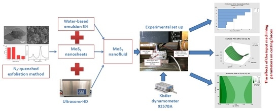
2.1. The Production of MoS2 Nanoparticles

The preparation of MoS2 nanosheets by liquid N2-queched bulk MoS2 was reported in [35]. Briefly, 500 mg of MoS2 bulk was transferred to 100 mL of 5% KOH solution under vigorous stirring for 30 min. The mixture was maintained at 80 °C for 24 h and then it was quickly quenched in liquid N2. The temperature dramatically dropped from 80 to −196 °C when the MoS2 solution was immersed in liquid N2. This prompt temperature decreasing not only expands the MoS2 but also allows for the intercalation of both K+ ions and N2 gas into the interlayer, resulting in exfoliating MoS2 nanosheets under the sonication synergistic. After quenching, the dispersion was sonicated at 20 kHz under a power of 400 W. The resulting material was collected through vacuum filtration with PVDF membranes (average pore size: 0.2 μm). The final product was dried in 50 °C under vacuum for 24 h. The Raman spectra of bulk MoS2 and MoS2 nanosheets powders were recorded using a Raman Spectrometer JobinYvon LabRAM HR800 (FOCAS Research Institute, Dublin, Ireland). Transmission electron microscopy (TEM) images were recorded using a JEM-2100F Field Emission Electron Microscope (JEOL Ltd., Tokyo, Japan).
Figure 1 displays the transmission electron microscopy (TEM) image, scanning electron microscopy (SEM) image, lateral size distribution and Raman spectra of MoS2 flake obtained from the N2-quenched exfoliation method [35]. A transparent to the electron beam corresponding to the sheet-like structures of MoS2 flakes with a lateral size of approximately several hundred nanometers was shown in Figure 1a and the thickness ranges from 10 to 20 nm. Figure 1b displays the SEM image of MoS2 flakes which clearly show the sheets morphology with the lateral size from several hundred nm to approximate 2 µm. Furthermore, a statistic was estimated from 75 objects in SEM images to evaluate the lateral size distribution of MoS2 nanosheets as shown in Figure 1c. MoS2 nanosheets almost reveal the lateral size smaller than 1 µm, which is consistent with the TEM data. In addition, the Raman spectra in Figure 1d reveal a typical of in-plane E12g and out-plane A1g Raman peaks of MoS2 flakes located at 376 and 403.2 cm−1, respectively, which highly agreed with the previous reports [36,37].

2.2. Experimental Set Up

The experimental devices consist of Mazak vertical center smart 530C (Yamazaki Mazak Corporation, Aichi, Japan), tool holder type with the designation SHIJIE BAP 400R-50-22-4T with the diameter of 50 mm, and APMT 1604 PDTR LT30 PVD submicron carbide inserts (LAMINA TECHNOLOGIES SA, Yverdons-les-Bains, Switzerland) with a flank angle of 11°, nose radius of 0.66 mm, and a TiAlN coating layer. The samples are AISI D2 steels (52 ÷ 60 HRC) with the dimensions of 90 mm × 48 mm × 50 mm and their chemical composition shown in Table 1.
The MQCL system includes Frigid-X Sub-Zero Vortex Tool Cooling Mist System (Nex Flow™ Air Products Corp, Richmond Hill, ON, Canada) compressed air, pressure stabilization device, water-based emulsion 5% and MoS2 nanoparticles. The experiment set up is shown in Figure 2.
To ensure the uniform suspension of MoS2 nanosheets in emulsion-based fluids, the prepared nanofluids are kept in Ultrasons-HD ultrasonicator (JP Selecta, Abrera (Barcelona), Spain), generating 400 W ultrasonic pulses at 40 kHz for 2 h to ensure the uniform distribution of the nanoparticles. In order to use the obtained nanofluids effectively and avoid the precipitation of agglomerated nanoparticles during the long time of machining, the nanofluid was placed in the 3000868-Ultrasons-HD and directly used for the MQCL system.
Measuring equipment consists of Kistler quartz three-component dynamometer 9257BA (Kistler Instruments (Pte) Ltd., Midview, Singapore).

2.3. Experiment Design

The fixed parameters for cutting condition include the feed rate of 0.012 mm/tooth, a depth of cut of 0.12 mm, air pressure of 0.6 MPa, flow rate of 30 mL/h; the room temperature 24 ÷ 27 °C; the temperature of output cool air through MQCL nozzle of 4 ÷ 8 °C. Box–Behnken experimental design is made with the help of Minitab 18.0 software (N03-T5 Embassy Garden, Ha Noi, Vietnam) (Table 2). Table A1 summarizes the design of experiment with test run order and output in term of cutting forces Fx, Fy, Fz. Each test run is repeated by three times under the same cutting parameters.

3. Results and Discussion

The Effects of Input Machining Parameters on Cutting Forces

The ANOVA analysis is carried out at a confidence level of 95% (i.e., 5% significance level). Table A2, Table A3 and Table A4 show the results of the ANOVA analysis. The regression models of cutting forces Fx, Fy, Fz with R2 equal to 89.96, 94.21, 98.17, respectively, are given below in Equations (1)–(3).
Fx = −1422 − 18.9X1 + 4.52X2 + 44.1X3 + 9.48X1 ∗ X1 − 0.0232X2 ∗ X2 − 0.383X3 ∗ X3
Fy = −2248 − 160.4X1 + 25.03X2 + 133.1X3 + 71.7X1 ∗ X1 − 0.1232X2 ∗ X2 − 1.198X3 ∗ X3
Fz = −2403 − 158.0X1 + 10.0X2 + 73.2X3 + 70.6X1 ∗ X1 − 0.0519X2 ∗ X2 − 0.621X3 ∗ X3
The Pareto charts of the standardized effects with α = 0.05 for the response parameters Fx, Fy, Fz are shown in Figure 3, Figure 4 and Figure 5. Hardness (x3) has the strongest influence on Fx, Fz, while nanoparticle concentration (x1) has a strongest influence on Fy and also causes strong effect on Fz. It can be seen that cutting speed (x2) has a very little effect on cutting forces Fx, Fy, Fz.
The quadratic effect CC (x3x3) reveals the significant influence on the investigated functions of Fx, Fy, and the quadratic effect AA (x1x1) exhibits the significant effect on the investigated functions of Fy, Fz. In addition, the quadratic effect BB (x2x2) has a strong influence on Fy. The other quadratic effects of x1x2, x1x3, x2x3 cause very little influences and are not investigated in the regression models. Studying the charts in Figure 3, Figure 4 and Figure 5, the proper selection of nanoparticle concentration and hardness is needed to study for the effects on cutting forces in order to improve the machining performance while retaining the good tool life and surface quality as well.
The surface and contour plots of investigated variables on cutting force Fx are shown in Figure 6, Figure 7 and Figure 8.
The graphs of effects of nanoparticle concentration and cutting speed with constant hardness of 56 HRC are shown in Figure 6. From Figure 6a, the cutting force Fx increases with the rise of cutting speed from 90 to 100 m/min and then decreases when cutting speed rises to 110 m/min, but the surface plot is contrast with the changes of nanoparticle concentration. Observed from Figure 6b, the aim for low cutting force Fx can achieve by using high level of cutting speed (110 m/min) and np of 1.0 wt.%. When holding cutting speed of 100 m/min or nanoparticle concentration of 1.0 wt.%, it can be clearly seen that the hardness factor has a very strong effect on cutting forces Fx (Figure 7 and Figure 8). The force Fx rapidly goes up with the rise of material hardness.
The surface and contour plots of nanoparticle concentration and cutting speed on cutting forces Fy, Fz while keeping the constant hardness of 56HRC are shown in Figure 9 and Figure 10.
From the surface and contour plots in Figure 9 and Figure 10, it clearly reveals that the value of nanoparticle concentration of 1.0 wt.% brings out the decrease of cutting forces Fy, Fz. For smallest values of Fy, cutting speed can be chosen from 95 to 105 m/min (Figure 9b), and for smallest values of Fz, it can range from 90 to 110 m/min (Figure 10b). Hence, depending on the specific conditions, these results could provide the useful guide for improving hard milling performance while ensuring the technical and economic characteristics.
The surface and contour plots of hardness and nanoparticle concentration on cutting forces Fy, Fz while cutting speed is constant with V = 100 m/min are shown in Figure 11 and Figure 12.
From the surface and contour plots in Figure 11 and Figure 12, it clearly reveals that the value of nanoparticle concentration about 1.0 wt.% also gives out the decrease of cutting forces Fy, Fz. The cutting forces Fy, Fz grow with the increase of material hardness from 52 to 56 HRC, but there is a little difference in the hardness range of 56–60 HRC. The force Fy exhibits the reducing trend while the force Fz increases.
The surface and contour plots of hardness and cutting speed on cutting forces Fy, Fz while nanoparticle concentration is constant with np = 1.0 wt.% are shown in Figure 13 and Figure 14. In general, when cutting speed increases, the forces Fy, Fz decrease but not much. From these results, nanoparticle concentration can be chosen by about 1.0 wt.% in combination with a low hardness value, and a high cutting speed can be used for increasing productivity.
In detail, Fy is the thrust force, the so-called springback of the work materials, which plays a significant role in hard machining and has a strong effect dimensional accuracy and flank wear. Moreover, it causes high contact stresses over the tool flank contact face and this is a distinguishing feature of hard machining. Fz is the main cutting force, which has a strong effect on the cutting performance and productivity. From the study, the technical guides will be given for selecting the cutting condition and making further studies.
In the machining of hardened steels with geometrically defined cutting tools, catastrophic failure causes the saw-tooth chip formation in the primary shear zone. Thermal stresses originate mainly in the intensive friction between the flank face and machined face. Moreover, the plastic deformation is very little, so the thermal stresses and intensive friction cause white layer [2]. Therefore, the presence of MoS2 nanosheet having a low friction coefficient and excellent lubricating property in MQCL-based fluid contributes to reducing the friction stresses in contact zones [38,39], from which the cutting forces decrease significantly and the machining performance improves.

4. Conclusions

In this study, MoS2 nanoparticles are produced by exfoliation of liquid N2–quenched bulk, which is the facile method owning to its highly efficient, green, and facile operation. The produced MoS2 nanosheets are directly used for the MQCL hard milling process. Box–Behnken experimental design with the help of ANOVA analysis is used to investigate the effects of three variables, including nanoparticle concentration, cutting speed, and material hardness on cutting force components Fx, Fy, Fz.
From the obtained results, hardness and nanoparticle concentration reveal the strongest influence on the cutting force functions. The nanoparticle concentration should be used with 1.0 wt.% for reducing cutting forces in combination with a high cutting speed of 110 m/min in order to achieve the technological and economic characteristics. The cutting force components grow up with the increase of hardness.
The machining performance of hard milling process improves under the MQCL condition by using an MQCL device named the Frigid-X Sub-Zero Vortex Tool Cooling Mist System with a real cooling effect based on the principle of the Ranque–Hilsch vortex tube. The cooling and lubricating effects significantly enhance due to the use of the novel MQCL device and MoS2 nanofluid with excellent lubricating property. Therefore, the normal coated cemented carbide inserts, such as APMT 1604 PDTR LT30, could be effectively used for the hard machining of AISI D2 (52–60 HRC) with a high cutting speed of 110 m/min, which is about 2.0–2.2 times higher than the manufacturer’s recommendations [40]. This will contribute to enlarge the cutting applicability and decrease the manufacturing cost.
Moreover, this is one of the first studies of this type of MQCL tool using nanofluid for difficult-to-cut materials. Compared to our previous study, which concentrated on the surface roughness, surface microstructure, and surface profile and used the commercial MoS2 nanoparticles [17], this work is a big development because MoS2 nanoparticles are produced by our own method and cutting forces Fx, Fy, Fz are investigated in detail, from which the technical guides are provided and further work can be made.
Furthermore, the MQCL tool only needs ordinary air rather than cryogenic CO2 or N2 for cooling, which will simplify the equipment and reduce the cost.
In further research, deeper studies are needed to focus on the effects of MoS2 nanoparticles on tool wear and tool life as well as the lubricating behavior in the cutting zone. In addition to this, the morphology, size and production methods of MoS2 nanosheets will be investigated.

Author Contributions

Conceptualization, P.Q.D., T.M.D., T.T.L. and D.V.T.; Data curation, N.M.T.; Formal analysis, P.Q.D., T.T.L., D.V.T., N.M.T. and N.V.T.; Investigation, P.Q.D., T.T.L., N.M.T. and N.V.T.; Methodology, P.Q.D., T.T.L., D.V.T., N.M.T. and N.V.T.; Project administration, T.M.D.; Resources, D.V.T.; Software, T.T.L., D.V.T. and N.V.T.; Supervision, N.V.T.; Validation, N.M.T.; Visualization, T.T.L.; Writing—original draft, P.Q.D., T.M.D., T.T.L. and D.V.T.; Writing—review & editing, P.Q.D., T.M.D., T.T.L. and D.V.T. All authors have read and agreed to the published version of the manuscript.

Funding

This research was funded by Vietnam Ministry of Education and Training with the project number of B2019-TNA-02.

Acknowledgments

The study had the support of Vietnam Ministry of Education and Training and Thai Nguyen University of Technology, Thai Nguyen University with the project number of B2019-TNA-02.

Conflicts of Interest

The authors declare no conflict of interest.

Appendix A

Table A1. Design of the experiment with test run order and output in terms of cutting forces.
Std
Order
Run
Order
PtTypeBlocksInput Machining ParametersResponse Variables
x1
(wt.%)
x2
(m/min)
x3
(HRC)
Fx
(N)
Fy
(N)
Fz
(N)
120210.5905660.50116.70179.90
230211.5905662.70101.30135.70
37210.51105643.7099.80131.83
441211.51105653.1090.08136.40
54210.51005245.40125.24157.80
639211.51005247.90103.10129.80
732210.51006052.6073.20120.48
814211.51006045.7769.90137.90
916211905241.4090.7098.37
10292111105237.4582.6097.70
1122211906072.2086.30168.90
12182111106045.0476.90149.53
13230111005657.4090.10140.85
14430111005650.0077.90134.94
15190111005653.7083.95137.90
1611210.5905661.50170.10178.70
1721211.5905650.40103.10136.00
1813210.51105655.40120.96173.52
1937211.51105652.20100.20142.79
2038210.51005242.8079.70151.65
2133211.51005252.40105.10145.79
2212210.51006054.3080.45154.08
239211.51006062.5987.80171.50
2428211905243.1083.9692.85
25452111105247.6099.50112.40
2610211906040.4068.53141.90
2722111106037.3080.83134.87
28150111005665.7094.90145.03
29360111005650.4084.60130.40
30270111005658.0589.75137.50
316210.5905646.20151.90160.10
3217211.5905658.60102.50138.70
335210.51105658.60124.90163.76
343211.51105656.40114.70140.28
3535210.51005243.5065.80112.00
3625211.51005252.6077.00141.55
3742210.51006061.9090.95145.90
381211.51006048.9070.10132.25
3931211905240.7787.90126.20
40262111105240.5057.2084.78
418211906052.6076.70142.50
42402111106066.0080.06136.51
43440111005664.6094.80142.85
44240111005644.7684.39140.22
45340111005654.6889.60141.37
Table A2. Results of the ANOVA analysis of cutting force Fx.
SourceDFAdj SSAdj MSF-Valuep-Value
Model61133.64188.9412.930.019
Linear3580.91193.6383.000.042
x110.000.0010.000.997
x2137.7037.7000.580.449
x31543.21543.2118.420.006
Square3552.73184.2442.850.050
x1*x1162.2262.2180.960.332
x2*x2159.7159.7060.930.342
x3*x31415.56415.5586.440.015
Error382452.3864.536
Lack-of-Fit6185.9430.9890.440.848
Pure Error322266.4570.827
Total443586.03
* represents the quadratic effect.
Table A3. Results of the ANOVA analysis of cutting force Fy.
SourceDFAdj SSAdj MSF-Valuep-Value
Model612,556.12092.78.470.000
Linear32569.2856.43.470.025
x111748.01748.07.070.011
x21352.4352.41.430.240
x31468.9468.91.900.176
Square39986.93329.013.470.000
x1*x113557.13557.114.390.001
x2*x211682.21682.26.810.013
x3*x314069.94069.916.470.000
Error389391.8247.2
Lack-of-Fit62198.1366.41.630.171
Pure Error327193.7224.8
Total4421,947.9
* represents the quadratic effect.
Table A4. Results of the ANOVA analysis of cutting force Fz.
SourceDFAdj SSAdj MSF-Valuep-Value
Model612,281.22046.96.910.000
Linear37035.72345.27.910.000
x111684.41684.45.680.022
x21379.6379.61.280.265
x314971.74971.716.780.000
Square35245.41748.55.900.002
x1*x113453.83453.811.660.002
x2*x21298.5298.51.010.322
x3*x311094.31094.33.690.062
Error3811,259.9296.3
Lack-of-Fit62278.0379.71.350.263
Pure Error328981.9280.7
Total4423,541.1
* represents the quadratic effect.

References

  1. Nagimova, A.; Perveen, A. A review on Laser Machining of hard to cut materials. Mater. Today Proc. 2019, 18, 2440–2447. [Google Scholar] [CrossRef]
  2. Davim, J.P. Machining of Hard Materials; Springer: London, UK, 2011. [Google Scholar]
  3. Zhang, K.; Deng, J.; Meng, R.; Gao, P.; Yue, H. Effect of nano-scale textures on cutting performance of WC/Co-based Ti55Al45N coated tools in dry cutting. Int. J. Refract. Met. Hard Mater. 2015, 51, 35–49. [Google Scholar] [CrossRef]
  4. Xing, Y.; Deng, J.; Zhao, J.; Zhang, G.; Zhang, K. Cutting performance and wear mechanism of nanoscale and microscale textured Al2O3/TiC ceramic tools in dry cutting of hardened steel. Int. J. Refract. Met. Hard Mater. 2014, 43, 46–58. [Google Scholar] [CrossRef]
  5. Bouacha, K.; Yallese, M.A.; Mabrouki, T.; Rigal, J.-F. Statistical analysis of surface roughness and cutting forces using response surface methodology in hard turning of AISI 52100 bearing steel with CBN tool. Int. J. Refract. Met. Hard Mater. 2010, 28, 349–361. [Google Scholar] [CrossRef]
  6. Su, Y.; Li, Z.; Li, L.; Wang, J.; Gao, H.; Wang, G. Cutting performance of micro-textured polycrystalline diamond tool in dry cutting. J. Manuf. Process. 2017, 27, 1–7. [Google Scholar] [CrossRef]
  7. Vignesh, M.; Ramanujam, R. Laser-assisted high Speed Machining of Inconel 718 Alloy; Elsevier BV: Amsterdam, The Netherlands, 2020; pp. 243–262. [Google Scholar]
  8. Venkatesan, K. Optimization of Surface Roughness and Power Consumption in laser-assisted machining of Inconel 718 by Taguchi based Response Surface Methodology. Mater. Today Proc. 2018, 5, 11326–11335. [Google Scholar] [CrossRef]
  9. Duc, M.T.; Long, T.T. Investigation of MQL-Employed Hard-Milling Process of S60C Steel Using Coated-Cemented Carbide Tools. J. Mech. Eng. Autom. 2016, 6, 128–132. [Google Scholar]
  10. Joshi, K.K.; Kumar, R. Anurag An Experimental Investigations in Turning of Incoloy 800 in Dry, MQL and Flood Cooling Conditions. Procedia Manuf. 2018, 20, 350–357. [Google Scholar] [CrossRef]
  11. Sani, A.S.A.; Rahim, E.A.; Sharif, S.; Sasahara, H. Machining performance of vegetable oil with phosphonium- and ammonium-based ionic liquids via MQL technique. J. Clean. Prod. 2019, 209, 947–964. [Google Scholar] [CrossRef]
  12. Minh, D.T.; The, L.T.; Bao, N.T. Performance of Al2O3 nanofluids in minimum quantity lubrication in hard milling of 60Si2Mn steel using cemented carbide tools. Adv. Mech. Eng. 2017, 9, 1–9. [Google Scholar] [CrossRef] [Green Version]
  13. Hegab, H.; Umer, U.; Soliman, M.; Kishawy, H.A. Effects of nano-cutting fluids on tool performance and chip morphology during machining Inconel 718. Int. J. Adv. Manuf. Technol. 2018, 96, 3449–3458. [Google Scholar] [CrossRef]
  14. Hegab, H.; Kishawy, H.A. Towards Sustainable Machining of Inconel 718 Using Nano-Fluid Minimum Quantity Lubrication. J. Manuf. Mater. Process. 2018, 2, 50. [Google Scholar] [CrossRef] [Green Version]
  15. Tran, M.-D.; Long, T.T.; Chien, T.Q. Performance Evaluation of MQL Parameters Using Al2O3 and MoS2 Nanofluids in Hard Turning 90CrSi Steel. Lubricants 2019, 7, 40. [Google Scholar] [CrossRef] [Green Version]
  16. Duc, T.M.; Long, T.T.; Dong, P.Q. Effect of the alumina nanofluid concentration on minimum quantity lubrication hard machining for sustainable production. Proc. Inst. Mech. Eng. Part C J. Mech. Eng. Sci. 2019, 233, 5977–5988. [Google Scholar] [CrossRef]
  17. Dong, P.Q.; Duc, T.M.; Long, T.T. Performance Evaluation of MQCL Hard Milling of SKD 11 Tool Steel Using MoS2 Nanofluid. Metals 2019, 9, 658. [Google Scholar] [CrossRef]
  18. Li, B.; Li, C.; Zhang, Y.; Wang, Y.; Jia, D.; Yang, M.; Zhang, Y.; Wu, Q.; Han, Z.; Sun, K. Heat transfer performance of MQL grinding with different nanofluids for Ni-based alloys using vegetable oil. J. Clean. Prod. 2017, 154, 1–11. [Google Scholar] [CrossRef]
  19. Pashmforoush, F.; Bagherinia, R.D. Influence of water-based copper nanofluid on wheel loading and surface roughness during grinding of Inconel 738 superalloy. J. Clean. Prod. 2018, 178, 363–372. [Google Scholar] [CrossRef]
  20. Lee, P.-H.; Nam, J.S.; Li, C.; Lee, S.W. An experimental study on micro-grinding process with nanofluid minimum quantity lubrication (MQL). Int. J. Precis. Eng. Manuf. 2012, 13, 331–338. [Google Scholar] [CrossRef]
  21. Zhang, Y.; Li, C.; Jia, D.; Li, B.; Wang, Y.; Yang, M.; Hou, Y.; Zhang, X. Experimental study on the effect of nanoparticle concentration on the lubricating property of nanofluids for MQL grinding of Ni-based alloy. J. Mater. Process. Technol. 2016, 232, 100–115. [Google Scholar] [CrossRef]
  22. Yıldırım, Ç.V.; Sarıkaya, M.; Kıvak, T.; Şirin, Ş. The effect of addition of hBN nanoparticles to nanofluid-MQL on tool wear patterns, tool life, roughness and temperature in turning of Ni-based Inconel 625. Tribol. Int. 2019, 134, 443–456. [Google Scholar] [CrossRef]
  23. Yıldırım, Ç.V. Investigation of hard turning performance of eco-friendly cooling strategies: Cryogenic cooling and nanofluid based MQL. Tribol. Int. 2020, 144, 106127. [Google Scholar] [CrossRef]
  24. Pervaiz, S.; Deiab, I.; Rashid, A.; Nicolescu, M. Minimal quantity cooling lubrication in turning of Ti6Al4V: Influence on surface roughness, cutting force and tool wear. Proc. Inst. Mech. Eng. Part B J. Eng. Manuf. 2015, 231, 1542–1558. [Google Scholar] [CrossRef]
  25. Maruda, R.W.; Krolczyk, G.M.; Feldshtein, E.; Nieslony, P.; Tyliszczak, B.; Pusavec, F. Tool wear characterizations in finish turning of AISI 1045 carbon steel for MQCL conditions. Wear 2017, 372, 54–67. [Google Scholar] [CrossRef]
  26. Maruda, R.W.; Krolczyk, G.M.; Feldshtein, E.; Pusavec, F.; Szydlowski, M.; Legutko, S.; Sobczak-Kupiec, A. A study on droplets sizes, their distribution and heat exchange for minimum quantity cooling lubrication (MQCL). Int. J. Mach. Tools Manuf. 2016, 100, 81–92. [Google Scholar] [CrossRef]
  27. Maruda, R.W.; Krolczyk, G.M.; Nieslony, P.; Królczyk, J.B.; Legutko, S. Chip Formation Zone Analysis During the Turning of Austenitic Stainless Steel 316L under MQCL Cooling Condition. Procedia Eng. 2016, 149, 297–304. [Google Scholar] [CrossRef] [Green Version]
  28. Maruda, R.W.; Feldshtein, E.; Legutko, S.; Królczyk, G.M. Research on emulsion mist generation in the conditions of minimum quantity cooling lubrication (MQCL). Teh. Vjesn. Tech. Gaz. 2015, 22, 1213–1218. [Google Scholar] [CrossRef] [Green Version]
  29. Duc, T.M.; Long, T.T.; Van Thanh, D. Evaluation of minimum quantity lubrication and minimum quantity cooling lubrication performance in hard drilling of Hardox 500 steel using Al2O3 nanofluid. Adv. Mech. Eng. 2020, 12, 1–12. [Google Scholar] [CrossRef]
  30. Zeng, Z.; Yin, Z.; Huang, X.; Li, H.; He, Q.; Lu, G.; Boey, F.; Zhang, H. Single-Layer Semiconducting Nanosheets: High-Yield Preparation and Device Fabrication. Angew. Chem. Int. Ed. 2011, 50, 11093–11097. [Google Scholar] [CrossRef]
  31. Lee, Y.-H.; Zhang, X.; Zhang, W.; Chang, M.-T.; Lin, C.-T.; Chang, K.-D.; Yu, Y.-C.; Wang, J.T.-W.; Chang, C.-S.; Li, L.-J.; et al. Synthesis of Large-Area MoS2 Atomic Layers with Chemical Vapor Deposition. Adv. Mater. 2012, 24, 2320–2325. [Google Scholar] [CrossRef] [Green Version]
  32. Liu, K.-K.; Zhang, W.; Lee, Y.-H.; Lin, Y.-C.; Chang, M.-T.; Su, C.Y.; Chang, C.-S.; Li, H.; Shi, Y.; Zhang, H.; et al. Growth of Large-Area and Highly Crystalline MoS2 Thin Layers on Insulating Substrates. Nano Lett. 2012, 12, 1538–1544. [Google Scholar] [CrossRef] [Green Version]
  33. Yu, Y.; Li, C.; Liu, Y.; Su, L.; Zhang, Y.; Cao, L. Controlled Scalable Synthesis of Uniform, High-Quality Monolayer and Few-layer MoS2 Films. Sci. Rep. 2013, 3, 1866. [Google Scholar] [CrossRef] [PubMed]
  34. Wu, S.; Huang, C.; Aivazian, G.; Ross, J.S.; Cobden, D.H.; Xu, X. Vapor–Solid Growth of High Optical Quality MoS2 Monolayers with Near-Unity Valley Polarization. ACS Nano 2013, 7, 2768–2772. [Google Scholar] [CrossRef] [PubMed] [Green Version]
  35. Van Thanh, D.; Pan, C.-C.; Chu, C.-W.; Wei, K.-H. Production of few-layer MoS2 nanosheets through exfoliation of liquid N2–quenched bulk MoS2. RSC Adv. 2014, 4, 15586–15589. [Google Scholar] [CrossRef]
  36. Nguyen, V.-T.; Yang, T.-Y.; Le, P.A.; Yen, P.-J.; Chueh, Y.-L.; Wei, K.-H. New Simultaneous Exfoliation and Doping Process for Generating MX2 Nanosheets for Electrocatalytic Hydrogen Evolution Reaction. ACS Appl. Mater. Interfaces 2019, 11, 14786–14795. [Google Scholar] [CrossRef]
  37. Nguyen, V.-T.; Le, P.A.; Hsu, Y.-C.; Wei, K.-H. Plasma-Induced Exfoliation Provides Onion-Like Graphene-Surrounded MoS2 Nanosheets for a Highly Efficient Hydrogen Evolution Reaction. ACS Appl. Mater. Interfaces 2020, 12, 11533–11542. [Google Scholar] [CrossRef]
  38. Rahmati, B.; Sarhan, A.A.; Sayuti, M. Morphology of surface generated by end milling AL6061-T6 using molybdenum disulfide (MoS2) nanolubrication in end milling machining. J. Clean. Prod. 2014, 66, 685–691. [Google Scholar] [CrossRef]
  39. Maruda, R.W.; Krolczyk, G.M.; Wojciechowski, S.; Żak, K.; Habrat, W.; Nieslony, P. Effects of extreme pressure and anti-wear additives on surface topography and tool wear during MQCL turning of AISI 1045 steel. J. Mech. Sci. Technol. 2018, 32, 1585–1591. [Google Scholar] [CrossRef]
  40. Applied Research of Nanofluids in MQL to Improve Hard Milling Performance of 60Si2Mn Steel Using Carbide Tools. Available online: https://wix.lamina tech.ch/img/catalog/1237.pdf (accessed on 5 June 2019).
Figure 1. (a) Transmission electron microscopy (TEM) image, (b) scanning electron microscopy (SEM) image, (c) Lateral size distribution and Raman spectra (d) of MoS2 nanosheets.
Lubricants 08 00062 g001
Figure 2. Experimental set up.
Lubricants 08 00062 g002
Figure 3. Pareto chart of effects of investigated factors on cutting force Fx. (A is x1: nanoparticle concentration, B is x2: cutting speed, C is x3: hardness, AA is the quadratic effect of nanoparticle concentration, BB is the quadratic effect of cutting speed, and CC is the quadratic effect of hardness).
Lubricants 08 00062 g003
Figure 4. Pareto chart of effects of investigated factors on cutting force Fy. (A is x1: nanoparticle concentration, B is x2: cutting speed, C is x3: hardness, AA is the quadratic effect of nanoparticle concentration, BB is the quadratic effect of cutting speed, and CC is the quadratic effect of hardness).
Lubricants 08 00062 g004
Figure 5. Pareto chart of effects of investigated factors on cutting force Fz. (A is x1: nanoparticle concentration, B is x2: cutting speed, C is x3: hardness, AA is the quadratic effect of nanoparticle concentration, BB is the quadratic effect of cutting speed, and CC is the quadratic effect of hardness).
Lubricants 08 00062 g005
Figure 6. Effects of nanoparticle concentration and cutting speed on cutting force Fx: (a) surface plot, (b) contour plot.
Lubricants 08 00062 g006
Figure 7. Effects of nanoparticle concentration and hardness on cutting force Fx: (a) surface plot, (b) contour plot.
Lubricants 08 00062 g007
Figure 8. Effects of cutting speed and hardness on cutting force Fx: (a) surface plot, (b) contour plot.
Lubricants 08 00062 g008
Figure 9. Effects of nanoparticle concentration and cutting speed on cutting force Fy: (a) surface plot, (b) contour plot.
Lubricants 08 00062 g009
Figure 10. Effects of nanoparticle concentration and cutting speed on cutting force Fz: (a) surface plot, (b) contour plot.
Lubricants 08 00062 g010
Figure 11. Effects of nanoparticle concentration and hardness on cutting force Fy: (a) surface plot, (b) contour plot.
Lubricants 08 00062 g011
Figure 12. Effects of nanoparticle concentration and hardness on cutting force Fz: (a) surface plot, (b) contour plot.
Lubricants 08 00062 g012
Figure 13. Effects of cutting speed and hardness on cutting force Fy: (a) surface plot, (b) contour plot.
Lubricants 08 00062 g013
Figure 14. Effects of cutting speed and hardness on cutting force Fz: (a) surface plot, (b) contour plot.
Lubricants 08 00062 g014
Table 1. Chemical composition of AISI D2 steel (According to American Society for Testing and Materials (ASTM) A681).
Chemical Composition (%)
CSiMnNiCrMoWVPS
1.4–1.60.1–0.60.1–0.60.511.0–13.00.7–1.20.2–0.50.5–1.10.030.03
Table 2. Control factors and their levels.
Control FactorUnitSymbolLevel
LowHigh
Nanoparticle
concentration (np)
wt.%x10.51.5
Cutting speed (V)m/minx290110
HardnessHRCx35260

