Article

Modeling of the Combined Effect of the Surface Roughness and Coatings in Contact Interaction

by
Irina Goryacheva
and
Anastasiya Yakovenko
*
Ishlinsky Institute for Problems in Mechanics RAS, Pr. Vernadskogo, 101-1, Moscow 119625, Russia
*
Author to whom correspondence should be addressed.
Lubricants 2024, 12(3), 68; https://doi.org/10.3390/lubricants12030068
Submission received: 7 January 2024 / Revised: 30 January 2024 / Accepted: 21 February 2024 / Published: 23 February 2024

Abstract

:
The model of indentation of a spherical punch with a rough surface into a thin elastic layer lying on an elastic half-space has been developed. A numerical-analytical solution is suggested based on the two-scales approach. At macroscale, the integral equation of the second kind is reduced to calculate the nominal contact characteristics, taking into account the surface layer thickness and its mechanical characteristics, as well as additional compliance due to surface roughness calculated from the microscale analysis. The influence of the punch roughness and the surface layer mechanical and geometrical characteristics on the nominal contact pressure distribution, on the nominal contact area and the indentation depth, as well as on the real contact area and pressures at the individual contact spots, is analyzed. The developed contact model can be used to analyze the indentation of the punch into the layered elastic base, taking into account the roughness of the punch surface, and can also be used to give a complete analysis of the roughness effect on the contact process at both scale levels. The results can be used to control the indentation of the rough-coated bodies.

Graphical Abstract

1. Introduction

One of the ways to improve the tribological properties of friction units is an application of various coatings on the surfaces of contacting bodies. The presence of such coatings, which leads to heterogeneity of the mechanical characteristics of contacting pair materials, should be taken into account in contact problem formulations and in analyses of the processes of friction and wear of tribojunctions. Simultaneously, the geometric heterogeneity of the surfaces of contacting bodies should also be taken into account, since the presence of the surface microrelief in the form of roughness and waviness leads to the concentration of contact and internal stresses near the contacting surfaces.
Therefore, it is necessary to develop contact models that take into account the heterogeneity of the contacting bodies, both geometric and mechanical. Contact problems of this kind are quite complex, and numerical methods are often used to solve them. To obtain analytical solutions, it is necessary to use any assumptions and simplifications regarding the shape and size of bodies, and their mechanical properties. For example, it is common to assume the thinness of these coatings relative to the size of the bodies in contact and the size of the contact region. Depending on the ratio of the elastic modulus of the coating and the substrate, various analytical approximations are used in this case. A number of models are developed for thin soft coatings. In [1], an approximate analytical solution for the problem of contact between two spheres with thin soft coatings was constructed, with assumptions of elliptical form of the contact pressure distribution. Another approximate solution of the problem of normal contact of an axisymmetric punch with a multilayer elastic base is given in [2]. The authors present the pressure distribution in the form of two parts, one of which corresponds to the case of a homogeneous half–space, and the other being the perturbing term, which is approximated by a series of base functions. A more accurate solution to the problem of indenting a coated body is obtained, for example, in [3], where the Hankel transform and numerical integration methods and assumptions of a specified type of contact pressure distribution (proportional to ( 1 r 2 / a 2 ) n , where a is the contact radius) are used. The authors investigated not only the contact characteristics, but also the stress state of the bodies. A fairly accurate solution to the problem of indenting a sphere into an elastic layer perfectly bonded to an elastic half-space was obtained in [4] by solving an infinite system of equations with the expression of contact pressure as a series that contains Tchebycheff polynomials. Using a similar method, the authors then solved the problem for a larger number of elastic layers bonded to an elastic half-space [5]. A simple analytical solution to the problem of indenting a spherical punch into an elastic layer perfectly bonded to an elastic half-space was obtained in [6]. The authors have shown that their solution has a sufficiently high accuracy for thin and thick coatings, as well as for coatings of arbitrary thickness in the case of a relatively small difference in the elastic modulus of the coating and the substrate. A large number of contact problems for elastic and viscoelastic bodies with coatings and analytical approaches to their solution can be found in the book [7]. However, due to the great difficulty of obtaining analytical solutions for the contact problems for layered bodies, various numerical methods are also developed. In [8], a general algorithm, which is based on dividing the contact region into annular areas, for solving such problem for the axisymmetric punch is presented. In [9], the boundary element method is used to validate an approximate solution of the contact problem of indenting an almost axisymmetric punch into layered elastic materials. The finite element method is also very popular, since it makes it possible to investigate a wide range of effects that occur during the contact of bodies with coatings [10].
A separate area is the study of the contact of deformable bodies, taking into account their surface roughness. Among the first research in this field, one can note the approach of Shtaerman [11], who proposed to take into account roughness in the form of an additional compliant layer deformed according to the Winkler model. Another approach is presented in [12], where the Greenwood–Williamson statistical model of roughness [13] is taken as a base. The authors have built the numerical solution according to an iterative scheme, which included first the deformations of the asperities, and then moved to deformations of the entire sphere. The solution of the contact problem for a smooth elastic sphere and a rigid rough base is presented in [14]. The authors also used the Greenwood–Williamson model, taking into account both the elastic deformations of the asperities and the bulk substrate. In [15], the contact of a rigid rough sphere with an elastic half-space was studied using the finite element method based on a fractal description of roughness. An analytical formula for the dependence of the contact stiffness on the load applied to the sphere was proposed there. The dependence of the real contact area on the load in contact interaction has been studied by many researchers. In [16], in addition to the numerical solution of the rough contact problem, the authors proposed an analytical formula for the real contact area in almost the entire range of applied loads. This formula was refined in [17], which made it possible to more accurately determine the area of the contactless region at large loads. Another analytical expression for the relationship between the real contact area and the applied load was obtained in [18], based on interpolation of numerical results obtained from the finite element analysis. A numerical model of contact of two rough elastic spheres is presented in [19]. Two contact regimes corresponding to very low loads (only one asperity in contact) and moderate loads (multiple asperities in contact) were studied, and some analytical expression for the transition load between these two regimes was derived there.
To study the effect of roughness on nominal contact characteristics (contact pressures, contact area size), an approach with the introduction of additional compliance due to roughness has been suggested in [11,20]. To describe the additional compliance due to roughness, the contact problem at the microscale is solved, and the resulting function of the additional displacement due to roughness is derived and used for the contact problem formulation at the macroscale [21,22]. The method to solve contact problems at the macroscale using the power dependence of the additional displacement on the nominal pressure was developed in [20,23,24]. The solution in this case can be obtained using the method of successive approximations for both cases of known or unknown in advance contact regions. A more accurate representation of the additional compliance function was obtained in [22] on the basis of the 3-D periodic contact problem solution. Using the approach of the additional compliance, the possibility of the full contact (equality of real and nominal contact areas) in the indentation of an axisymmetric punch into an elastic half-space with a rough surface was investigated in [25]. Another approach to take into account the effect of roughness on the distribution of the nominal contact pressures is given in [26]. The authors present the deformations as the sum of deformations of asperities and bulk deformations using the Persson’s rough contact theory for determination of the first ones. Numerical methods are also used to calculate the distribution of the nominal contact pressure in the contact of rough bodies. For example, in [27], the finite element method was applied for the analysis of the nominal contact characteristics for the given microgeometry parameters.
Thus, taking into account the presence of coatings on contacting bodies or their surface roughness significantly complicates the formulation and solution of contact problems. There are a few papers where the attempts to take into account both of these factors were made. For example, the contact problem for two half-spaces, one of which is rigid with a rough surface and another one is modeled by the layer bonded to the elastic base and has a smooth surface, was considered in [28]. The author used the Greenwood–Williamson roughness model and approximate solution of Chen and Engel [2] for a multilayer elastic half-space. Numerical results are presented there for the given values of the layer thickness, the ratio of the elastic modulus of the layer and the base, and the roughness parameters. A numerical solution for the contact of cylindrical punch with real roughness (which was determined based on profilogram data) and layered elastic half-plane was obtained for 2D contact problem formulation in [29]. The effect of specific roughness parameters on the distribution of contact pressures in the presence and absence of the layer of a given thickness was investigated. A numerical approximate solution of the contact problem for a rough sphere and a layered elastic base using the boundary element method and the Hankel transform, as well as the additional compliance function [22] due to the presence of microgeometry on the indenter surface, is presented in [30]. Thus, it can be concluded that, until now, only the numerical solutions were developed to study the contact problems for the layered elastic bodies, taking into account their macroshape and surface roughness parameters. Moreover, the study of the influence of roughness parameters on contact characteristics (both nominal and real) in the case of layered bodies is also incomplete.
In this paper, the solution of the contact problem for a rough spherical punch and an elastic half-space covered by a thin soft elastic layer is developed. The use of approximation of a relatively thin soft layer lying without friction or perfectly bonded to an elastic half-space makes it possible to reduce the problem to the analysis of an integral equation with a nonlinear non-integral term, depending both on the parameters of the punch microgeometry and the mechanical and geometric characteristics of the surface layer. The numerical-analytical solution of the problem is developed, and allows us to draw some general conclusions about the influence of both the roughness parameters (size and location density of asperities) and the mechanical and geometric parameters of the surface layer on the contact characteristics (nominal and real contact area, nominal and real contact pressure distributions, approach of the contacting bodies under loading, etc.). The complete (in comparison with the previous results) analysis of roughness parameters on the characteristics of contact interaction at both macro and microlevels is performed. Moreover, the main integral equation, obtained in analytical form, makes it possible to evaluate the nature of the surface parameters effect on the nominal contact characteristics.
The manuscript is organized as follows: Section 2 presents a problem statement in general form and the derivation of the main integral equation to solve the problem. Section 3 includes a consideration of the contact at the microscale and the determination of the additional displacement function. In Section 4, a general scheme to solve the main integral equation and to calculate the contact characteristics at macro and microscale is presented; and also the analysis of the surface layer on the real and nominal contact characteristics (pressure distribution, contact area, etc.) is given there. In Section 5, the effect of the punch roughness on the nominal and real contact characteristics by comparing the results obtained for the rough and smooth punches indenting into the layered and homogeneous elastic base is analyzed. In Section 6, the influence of the roughness parameters on the contact characteristics for the layered elastic half-space is investigated. Finally, in Section 7, some conclusions about the effects of the surface roughness and coatings in the indentation process are made.

2. Problem Statement

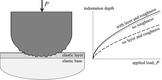
Let us consider the indentation of an axisymmetric punch, whose macroshape is described by the function f ( r ) = r 2 / ( 2 R ) (R is the curvature of the punch contacting surface), into an elastic layer (1) of thickness h, lying on an elastic half-space (2) (Figure 1). It is assumed that there are no shear stresses between the punch and the layer that takes place at a negligible friction coefficient. The punch surface has a roughness determined by the shape of asperities, the characteristic size of which is much smaller than the punch size, and by the density of the asperities distribution on the punch surface.
The problem under consideration has axial symmetry, so the nominal contact area is a circle region of radius a.
It is shown in [31] that in the case of a thin surface layer (practically at h < a ), the main integral equation for determining the distribution of the contact pressure p ( r ) in the problem of indenting an axisymmetric smooth punch into a two-layer elastic base can be reduced to the form
4 A 1 π E 1 0 a p ( r ) K ( 2 r r r + r ) r d r r + r + C p ( r ) = D f ( r ) ,   r a ,
where K ( x ) is the is the complete elliptic integral of the first kind, C = 2 A 2 h / E 1 , E 1 = E 1 / ( 1 ν 1 2 ) , E1 and ν 1 are the Young’s modulus and Poisson’s ratio of the surface layer, D is the indentation depth, and coefficients A1 and A2 depend on the relative mechanical characteristics of the layer and the half-space and the boundary condition between them (no friction or complete adhesion). In the case of equality of the Poisson’s ratios of the layer and the half-space ( ν 1 = ν 2 = ν ) A 1 = n = E 1 / E 2 = E 1 / E 2 , where E 2 = E 2 / ( 1 ν 2 2 ) , E2 and ν 2 are the Young’s modulus and Poisson’s ratio of the half-space. The coefficient A2 is 0.5 for the no-friction condition between the layer and the half-space, and in the case of the complete adhesion, it is determined as [31]:
A 2 = ( 1 n ) ( 1 2 ν ) ( 1 + n ( 1 2 ν ) ) 2 ( 1 ν ) 2 .
We consider only the case when the layer is softer than the half-space, that is E 1 < E 2 . Then, the coefficient A2 is always positive, since n < 1 . If E 1 = E 2 , that is n = 1 , then, based on (2), the coefficient A2 is equal to zero, and Equation (1) goes into the equation of the axisymmetric contact problem for an elastic half-space [32]. Note that in the case of an incompressible thin surface elastic layer ( ν = 0.5 ) bonded to an elastic half-space, the main Equation (1) is not applicable.
The presence of roughness on the punch contacting surface leads to a change in contact characteristics at the macroscale. It is shown in [22] that, due to roughness, an additional displacement of the layer boundary takes place at each point of the contact surface, which is determined by the distribution of the nominal contact pressure p ( r ) within the nominal contact area. In general, this dependence can be written as A [ p ( r ) ] , where A is some operator determined by solving the contact problem at the microscale. Note that the additional compliance due to roughness in the form of a linear function on contact pressure was first proposed in [11]. So, taking into account the roughness of the punch contacting surface, the integral Equation (3) takes the form
4 A 1 π E 1 0 a p ( r ) K ( 2 r r r + r ) r d r r + r + C p ( r ) + A [ p ( r ) ] = D f ( r ) ,   r a .
The radius of the contact area a is not known in advance, but it can be found from the condition p ( a ) = 0 (due to smoothness of the punch shape at the macroscale). Taking into account the considered punch shape at the macroscale, this condition allows us to reduce Equation (3) to (for r a ):
4 A 1 π E 1 0 a ( K ( 2 r r r + r ) 1 r + r K ( 2 a r a + r ) 1 a + r ) p ( r ) r d r + C p ( r ) + A [ p ( r ) ] = a 2 r 2 2 R .
If E 2 E 1 , Equation (4) corresponds to the indentation of the rough spherical punch into a thin layer lying without friction or bonded (compressible material) to a rigid base [33].
It is also necessary to add the following equilibrium condition to Equation (4):
2 π 0 a p ( r ) r d r = P ,
where P is the load applied to the punch (Figure 1).
Equations (4) and (5) allow us to calculate the nominal contact pressure distribution and the nominal contact radius at macroscale if the function A [ p ] is known.

3. Calculation of the Additional Displacement Function A [ p ]

It is assumed that the characteristic size of the asperity, for example, the curvature radius Ra is much smaller than the radius a of the circular nominal contact area at the macroscale, and the number of contacting asperities inside the nominal contact area is quite large. Moreover, it is assumed that the spot radius is much smaller than the surface layer thickness h. Then, as shown in [21], the additional displacement function A [ p ] can be determined from the solution of the contact problem for two half-spaces loaded by the nominal pressure p: a rigid one with a rough surface and an elastic one with a smooth surface (Figure 2). Let us describe the roughness as a set of regularly spaced identical asperities with the curvature radius Ra and the location density N ¯ (the number of asperities per unit area). To simplify the calculations, it is assumed that all asperities have the same height and spherical shape of the contacting surface, which is described by the function r 2 / ( 2 R a ) .
A general approach to solving periodic contact problems in a spatial formulation is presented in [34]. In the case of a periodic single-level system of punches modeling the surface roughness, the additional displacement of the layer boundary A [ p ] due to surface roughness can be defined as the difference between the indentation depth d of the punches and the displacement d of the layer boundary, everywhere loaded with the constant nominal pressure. The expression for this function for spherical asperities has the form [35]:
A [ p ] = d d = b 2 R a 2 p E 1 B ¯ 2 b 2 .
Here B ¯ = 1 / π N ¯ , and the radius b of the contact spot is found from the relation [35]
p ( B ¯ 2 arccos ( b B ¯ ) + b B ¯ 2 b 2 ) = 2 E 1 b 3 3 R a .
Note that for a random distribution of asperities in height, the similar approach can be used for the calculation of the additional displacement function, taking into account the mutual influence of asperities.

4. Calculation of the Contact Characteristics at the Macroscale

To calculate the distribution of the contact pressures p ( r ) from Equation (4), taking into account the additional displacement function A [ p ] (6), the method of successive approximations is used. Below, we present the method to calculate the additional displacement function for some given geometric characteristics of punch roughness, and then an algorithm for constructing an approximate solution of the contact problem and an analysis of its convergence.

4.1. Additional Displacement Function

It is impossible to reduce an analytical expression for operator A from Equations (6) and (7). As shown in [21], the additional displacement due to the presence of surface roughness is quite satisfactorily approximated by a power function of the nominal pressures (before the saturation of the real contact area takes place). Following this conclusion, the additional displacement function A [ p ] is approximated by a power function B p β on an arbitrary segment of the nominal pressure variation, and then we determine the coefficient B and the exponent β of this function by minimizing the deviations of the calculated values from the approximating function at some set of points p i using, for example, the method of least squares, that is:
i = 1 M ( A [ p i ] B p i β ) 2 min ,
where i is the point number and M is the total number of points.
It follows from Equations (6) and (7) that the additional displacement function depends on the nominal pressure p, the mechanical properties of the layer E 1 , as well as the roughness parameters N ¯ and Ra. As an example, the approximating function for the range of nominal pressures from zero to 0.025 E 1 is calculated. Thus, in the case of asperities located at the nodes of a quadratic lattice with a pitch l, the value N ¯ R a 2 = 4 corresponds to the case l = 0.5 R a . The range of nominal pressure values, where A [ p ] is approximated by a power function, was chosen arbitrarily, but in a way that the nominal pressures found at the macroscale were included in this interval. In our calculations, we considered both a uniform partition of this region with a step Δ p = 0.0001 E 1 and a non-uniform mesh with a denser partition near zero. The application of the least squares method gives the following parameter values: B = 0.092 R a / E 1 β and β = 0.491 for a uniform grid, B = 0.093 R a / E 1 β and β = 0.493 for a non-uniform grid. Based on the obtained results, for the further calculations at macroscale (see Section 2), the values of the parameters B = 0.1 R a / E 1 β and β = 0.5 are taken. The error of such approximation does not exceed 8% over almost the entire interval (from 0.0025 E 1 to 0.025 E 1 ), with the exception of a small region near zero.

4.2. Nominal Contact Pressure Calculation

4.2.1. Calculation Method

For calculation of the nominal contact pressure distribution p ( r ) , we use the function B p β (see Section 4.1), which approximates the additional displacement A [ p ] in the integral Equation (4) for fixed parameters of the microgeometry of the surface of the spherical punch. To solve Equation (4), we first reduce it to the form p ( r ) = F ( r , p ( r ) ) , where F is a function selected based on Equation (4), and then use the method of successive approximations. The function F can have different forms; the convergence of the method, which is based on the sequential calculation of approximations of the desired function according to the formula p i + 1 = F ( r , p i ) , depends on its choice.
To implement the calculation method, based on (4), the following form of the function F is considered:
F ( r , p ( r ) ) = 1 C + k ¯ ( a 2 r 2 2 R 4 A 1 π E 1 0 a p i ( K ( 2 r r r + r ) 1 r + r K ( 2 a r a + r ) 1 a + r ) p ( r ) r d r B p β ( r ) + k ¯ p ( r ) ) ,
and, accordingly, the following iterative scheme is applied:
p i + 1 = 1 C + k ¯ ( a 2 r 2 2 R 4 A 1 π E 1 0 a ( K ( 2 r r r + r ) 1 r + r K ( 2 a r a + r ) 1 a + r ) p i r d r B p i β + k ¯ p i ) ,
where k ¯ = k E 2 / a , and k is the non-negative integer.
For numerical calculations, the following dimensionless values are introduced:
r ˜ = r a ,   R ˜ = R a ,   p ˜ = p E 2 ,   B ˜ = B E 2 β a ,   C ˜ = C E 2 a ,   P ˜ = P E 2 a 2 .
Then Equation (8) is written in dimensionless form as
p i + 1 = 1 C ˜ + k ( 1 r ˜ 2 2 R ˜ 4 A 1 π n 0 1 ( K ( 2 r ˜ r ˜ r ˜ + r ˜ ) 1 r ˜ + r ˜ K ( 2 r ˜ 1 + r ˜ ) 1 1 + r ˜ ) p ˜ i r ˜ d r ˜ B ˜ p ˜ i β + k p ˜ i ) .
Note that the calculation algorithm assumes that the value of a is given, and the load is determined based on the equilibrium Equation (5).

4.2.2. Pressure Distribution Analysis

As follows from (8), the nominal contact pressure is determined by the following parameters: the coefficients A1 and A2, which depend on the ratio of the mechanical properties of the layer and the half-space and boundary condition between them, the punch curvature radius R, the layer thickness h, and the parameters B and β depending on the roughness parameters. The coefficient A1 and the layer thickness h are included in (9) through the parameter C.
Numerical calculations have been performed with the following values of the defining parameters: h = 0.5 a , R = 25 a , R a = 0.1 a , and n = E 1 / E 2 = 0.5 . For simplicity, we assume that ν 1 = ν 2 , then A 1 = n . Also, for definiteness, we consider the case when the layer lies on the half-space without friction, then A 2 = 0.5 . If the layer is perfectly bonded to the half-space, then the coefficient A2 is determined by formula (2). Finally, from the solution of the problem at the microscale with roughness parameters N ¯ R a 2 = 4 , it was found (see Section 4.1) that B = 0.1 R a / E 1 β and β = 0.5 . Thus, we have all the necessary dimensionless parameters (9) to solve the integral Equation (10) numerically.
Let us consider the iterative scheme (10) assuming k = 0 and p ˜ 0 ( r ˜ ) 0 as the first approximation. Then, we get that p ˜ 1 ( r ˜ ) = ( 1 r ˜ 2 ) / ( 2 C ˜ R ˜ ) . Subsequent approximations, calculated using formula (10), show that at each step, the difference between the contact pressure distribution and that obtained at the previous step becomes less and less. Calculations were carried out until this difference in absolute value over the entire contact area does not exceed a certain specified small value.
Let us denote the radius of the nominal contact area for the considered parameters of roughness and thin layer as a0 ( a 0 = 0.04 R ) and fix the load P ( P = 2.72 × 10 5 E 2 R 2 ) found in this case. When studying the distribution of the nominal contact pressures in other cases (with other values of the defining parameters of the problem), the radius of the nominal contact area a is selected in such a way that load P = 2.72 × 10 5 E 2 R 2 , so it is the same for all the cases under consideration.
To study the influence of the surface layer on the contact characteristics, the results obtained for the indentation of the rough punch into the elastic layer on the elastic half-space are compared with the results obtained for the indentation of the rough punch into the homogeneous elastic half-space. For the homogeneous elastic half-space, using the method described in Section 4.1, we obtain the following parameters in power function B p β , which describes the additional displacement A [ p ] due to roughness: B = 0.1 R a / E 2 β , β = 0.5 , and the approximation region is from 0.0025 E 2 to 0.025 E 2 . So the integral Equation (4) for the nominal pressure distribution in contact of the rough punch and the elastic half-space takes the form
4 A 1 π E 1 0 a ( K ( 2 r r r + r ) 1 r + r K ( 2 a r a + r ) 1 a + r ) p ( r ) r d r + B p β ( r ) = a 2 r 2 2 R .
This integral equation is also solved by the method of successive approximations using the iterative scheme (8) with C = 0 and k = 1 .
Figure 3 illustrates the pressure distributions calculated for the rough punch with fixed roughness parameters (see Section 4.1) and a fixed load value P = 2.72 × 10 5 E 2 R 2 , indenting into the layered and homogeneous elastic half-space. The radial coordinate is dimensionless by the radius of the contact area a0 corresponding to the problem of indentation of the punch into the elastic layer on the elastic half-space, that is a 0 = 0.04 R . It follows from the results that the presence of a thin soft layer on the half-space surface leads to a noticeable decrease in the nominal contact pressures in the center of the nominal contact area and an increase in the radius of the nominal contact area. Additionally, as shown by numerical calculations carried out with a finer partitioning step, the derivative of the function p ( r ) at the boundary of the nominal contact area in the case of the rough punch is equal to zero.

4.3. Real Contact Area

The real contact area of the rough punch and the elastic base is determined from [22]:
A r = 2 π 0 a λ [ p ( r ) ] r d r ,
where λ [ p ] is the relative contact area determined from the solution of the contact problem at the microscale. In the case of the roughness modeled by the periodic system of asperities (see Section 3), we can write for the function λ [ p ]
λ = N ¯ π b 2 ,
where the radius or the individual contact spot b is determined by formula (7) for the specific value of the nominal pressure p. Hence, for the ratio of the real contact area Ar to the nominal one An, we derive
A r A n = 2 a 2 0 a λ [ p ( r ) ] r d r .
The integral in this expression is calculated numerically using the results of calculation of the nominal contact pressures (see Section 4.2.2), as well as the solution of the problem at the microscale. For the parameters of roughness, layer thickness and its Young’s modulus considered in Section 4.2.2, and the fixed load P = 2.72 × 10 5 E 2 R 2 , it was obtained that A r = 0.185 A n , where A n = π a 0 2 . This means, in this case, the real contact area is slightly more than 18% of the nominal one.
In the case of indentation of the considered rough punch into the homogeneous elastic half-space under the action of the same load P, the real contact area, based on calculations, is slightly more than 17% of the nominal one, namely A r = 0.172 A n . Moreover, the nominal contact area An is equal to 0.564 π a 0 2 , that is, it is reduced by almost half compared to the indentation into the layered base. Thus, the presence on the elastic half-space surface of a thin layer, characterized by a smaller elastic modulus compared to the half-space material, increases the values of both the relative contact area A r / A n and the real one Ar.
Figure 4 illustrates the dependence of the relative contact area on the applied load for the rough punch indenting into the layered elastic base (solid lines) and into the homogeneous elastic half-space (dashed line). It follows from the results that the relative contact area is larger if the punch is indented into the layered base for all values of the applied load P. So, because of the nominal contact area for the layered base is larger, the presence of a soft thin layer on the half-space surface leads to an increase in the real contact area Ar.
Note that at low values of the applied load P, some assumptions regarding the smallness of the layer thickness and the asperities size relative to the radius of the nominal contact area are not fulfilled. So the calculated results in these cases must be compared to the models, which are not based on these assumptions.

4.4. Maximum Value of the Real Contact Pressure

Local maxima of the real contact pressures are observed in the center of each contact spot. The value of these maxima is determined by the following expression [34]:
p max = 2 E 1 b π R a + 2 p π arcsin ( b B ¯ ) ,
where B ¯ = 1 / π N ¯ , and the size b of the contact spot is determined from the contact problem at the microscale (Section 3) for the specific value of the nominal pressure p from Formula (7). Therefore, the maximum value of pressure on a single contact spot is observed in the center of the nominal contact area, where the nominal pressure has a maximum value. Numerical calculations show that for the roughness parameters and layer characteristics considered in Section 4.2.2 and the fixed load P = 2.72 × 10 5 E 2 R 2 , the maximum value of the nominal contact pressure is 0.01 E 2 . Then, the maximum pressure value on a single contact spot for the considered roughness parameters ( R a = 0.004 R , N ¯ = 250000 R 2 ) is equal to 0.053 E 2 .
In the case of indentation of the punch with the same roughness parameters into the homogeneous elastic half-space, the maximum pressure on a single contact spot, as follows from (13) and the results presented in Section 4.2.2, is 0.097 E 2 . Figure 5 shows the dependences of pmax on the load applied to the rough punch for two bases under consideration. The results indicate that the presence of a thin soft layer leads to a noticeable decrease both in the nominal and real contact pressures, which take place under a given value of the load applied to the punch.

4.5. Indentation Depth

Based on Equation (3), the depth of indentation of the punch into the layer lying on the half-space is determined by the following expression:
D = 2 A 1 E 1 0 a p ( r ) d r + C p ( 0 ) + A [ p ( 0 ) ] .
For the values of the roughness parameters and layer characteristics considered in Section 4.2.2, and the constant load P equal to 2.72 × 10 5 E 2 R 2 , the indentation depth D of the punch into the elastic layer lying on the elastic half-space is equal to 1.038 × 10 3 R . This is a little more than 5% of the layer thickness ( D = 0.052 h ). The maximum indentation value due to roughness is equal to 5.711 × 10 5 R and achieved in the center of the contact area, where the nominal pressure is maximum. It is less than half a percent of the layer thickness.
The dependences of the depth of indentation of the rough punch into the two considered deformable bases (elastic half-space with and without the surface layer) on the force applied to it are presented in Figure 6. The results indicate that the presence of a thin soft layer on the half-space surface reduces the contact stiffness, equal to the ratio of the load to the indentation depth.

5. Comparative Analysis of Contact Characteristics in Indentation of the Rough and Smooth Punches into the Coated and Homogeneous Elastic Half-Space

To analyze the punch roughness effect, in this section, we compare the results resulting from the model developed in this study with the contact characteristics calculated for the smooth punch penetrating in the coated or uncoated elastic half-space. For the smooth punch, the contact pressure in the case of the coated half-space is calculated numerically from Equation (3), where the term A [ p ] is zero, using the iteration scheme (8) with B = 0 and k = 1 . In the case of the uncoated half-space, the contact pressure is determined using the Hertz theory [33].
Figure 7 illustrates the distributions of the nominal contact pressures for two cases under consideration. The radial coordinate is dimensioned by the radius of the contact area a 0 = 0.04 R , corresponding to the indentation of the rough punch into the layered elastic base. In each case, the radius of the contact area was selected in such a way that the load P applied to the punch was constant and equal to 2.72 × 10 5 E 2 R 2 . The results indicate that, both for the rough and smooth punches indenting into the homogeneous elastic half-space, the radius of the nominal contact area is smaller and the nominal contact pressure in the central part is higher than they indent into the layered base. The presence of the roughness on the punch surface leads to an increase in the size of the nominal contact area, to a decrease in the nominal contact pressure under the central part of the punch and to a zero tangent of the function p ( r ) at the boundary of the nominal contact area (lines 1 and 2). This fact for an elastic thick strip was proved in [21].
Figure 8 illustrates the dependence of the indentation depth on the load applied to the rough (1,2) and smooth (1′,2′) punches. The punch roughness parameters, the thickness, and mechanical properties of the surface layer under consideration are described in Section 4.2.2. The depth of indentation of the smooth punch into the layered elastic half-space is equal to 1.003 × 10 3 R , and into the homogeneous elastic half-space it is equal to 7.418 × 10 4 R at the fixed load P = 2.72 × 10 5 E 2 R 2 . Comparison with the results of Section 4.5, where the indentation of the rough punch into the homogeneous and layered bases is studied, shows that the presence of the roughness leads to an increase in the indentation depth under the fixed load.

6. Influence of Roughness Parameters on Contact Characteristics

In Section 3, it was shown that in the case of modeling the punch surface roughness by the periodic system of identical asperities, the additional displacement function A [ p ] depends on two parameters. They are the curvature radius of asperities Ra and the density of their location N ¯ (the number of asperities per unit area). As shown in Section 4.1, the parameters B and β of the power function B p β approximated the additional compliance of the layer depend only on the product N ¯ R a 2 . For instance, for N ¯ R a 2 = 4 , the parameter values B = 0.1 R a / E 1 β and β = 0.5 were obtained.
To analyze the influence of the roughness parameters on the contact characteristics, two more values of the product N ¯ R a 2 are considered: N ¯ R a 2 = 1 and N ¯ R a 2 = 0.25 (Table 1). Using the approximation procedure described in Section 4.1, we obtain B = 0.3 R a / E 1 β and β = 0.53 for N ¯ R a 2 = 1 , B = R a / E 1 β and β = 0.57 for N ¯ R a 2 = 0.25 . The discrepancies in the results calculated from Equations (6) and (7) and based on the approximating function in these cases do not exceed 5% for the nominal pressures in the range from 0.0025 E 1 to 0.025 E 1 , with the exception of a small region near zero value of pressure. Note that the values of the parameter B presented in Table 1 are obtained in units R a / E 1 β . So they are different for different curvature radii of asperities.
Let us consider three values of the curvature radii of asperities Ra and three values of their distribution density N ¯ (Table 1). The procedure for determining the parameters B and β presented in Table 1 is described in Section 4.1. Note that the first line of the table corresponds to the roughness parameters used in the numerical calculations of Section 4 ( R a = 0.004 R and N ¯ = 250000 R 2 ).
Figure 9 illustrates the dependences of the additional displacement function on the nominal pressure p for different values of the roughness parameters N ¯ (a) and Ra (b). It follows from the results that a decrease in both the location density of asperities and the radius of their curvature leads to an increase in the additional displacement at a constant value of the nominal pressure. However, variation of the parameter N ¯ , which is equivalent to changing the distance between asperities, has a greater influence on the additional displacement due to roughness, as follows from Figure 9a. The calculation results also show that the approximating function gives the values of the additional displacement function closed to the values obtained from Equations (6) and (7).
The analysis of the surface roughness effect on the nominal pressure distribution in the contact of the spherical punch with the layered base has been performed based on the iterative scheme (8) with k = 0 and k = 1 .
Figure 10 illustrates the distribution of the nominal contact pressures for the rough punches with different values of the asperities density. The radial coordinate in Figure 10 is dimensioned by the radius a0 of the nominal contact area corresponding to the rough punch with N ¯ = 250000 R 2 . As follows from the results, a decrease in the density N ¯ of asperities leads to a decrease in the value of the nominal contact pressure in the center of the nominal contact area and an increase in the radius of the contact area itself. As calculations show, a decrease in the curvature radius of asperities Ra leads to a similar result, but less noticeable. Numerical calculations also show that a decrease in the values of the roughness parameters N ¯ and Ra also leads to a decrease in the relative contact area A r / A n and an increase in the indentation depth D and the local maximum pmax of the real contact pressure. Thus, by changing the microgeometry of the punch surface, it is possible to control the additional compliance of the deformable base, and therefore to achieve the required values of the contact characteristics both at macro and microscale.
The presented dependencies illustrating the roughness parameters effect on the nominal and real contact characteristics are in good qualitative consistency with the results of the real and nominal contact characteristics analysis in indentation of rough punches into a homogeneous elastic half-space [22,24], and also demonstrate the surface layer thickness and mechanical properties influence on the nominal and real contact characteristics under consideration.

7. Conclusions

A numerical-analytical solution of the contact problem for an axisymmetric rough punch indenting into a thin elastic layer lying on an elastic half-space is proposed. It is assumed that the elastic modulus of the layer is less than the elastic modulus of the base. To solve the problem, a two-scale approach is used. In the frame of this approach, the solution to the contact problem at the microscale (the scale of the asperities radius and contact density) obtained with the localization principle is used to construct an integral equation to determine the nominal contact pressure and nominal contact area, taking into account the punch roughness effect.
Analysis of the contact problem solution makes it possible to conclude that the presence of a thin elastic surface layer leads to a change in both nominal and real contact characteristics. So, at the macroscale, the presence of a thin soft layer leads to an increase in the nominal contact area, to a noticeable decrease in the maximum values of the nominal contact pressures and an increase in the indentation depth. At the microscale, the existence of the thin soft surface layer leads to a decrease in the maximum real contact pressures concentrated on individual contact spots (under asperities) and to an increase in the real contact area.
The punch roughness effect (in comparison with the case of the smooth punch) consists of an increase in the nominal contact area and decrease in the nominal contact pressures. Moreover, a decrease in the asperities density (number of asperities at the unit area) or the radius of their curvature results in an increase in the nominal contact area and a decrease in the value of the nominal contact pressure in the central part of the nominal contact region of the punch and the two-layer deformable base.
The resulting solution allows us to study the combined effect of the presence of microrelief and soft coatings on the surface of contact bodies in a contact interaction. Moreover, the presented analysis of the influence of roughness parameters on the additional compliance of bodies can be used to select a microrelief and coating mechanical and geometrical characteristics in order to achieve the necessary indentation values, and also to control the stress distribution near the contact area.
Note that in this study, the materials of deformable bodies were considered to be linearly elastic and isotropic, which imposes restrictions on the magnitude of deformations. As a further development of the presented results, the plastic deformations will be included in the model, which are of great importance in determining the contact characteristics at macro and microscales [36].

Author Contributions

Conceptualization, I.G.; methodology, I.G. and A.Y.; software, A.Y.; validation, I.G.; formal analysis, A.Y.; writing—original draft preparation, A.Y.; writing—review and editing, I.G. and A.Y.; visualization, A.Y.; supervision, I.G.; project administration, I.G.; funding acquisition, I.G. All authors have read and agreed to the published version of the manuscript.

Funding

This research was funded by the Russian Science Foundation, grant number 22-49-02010.

Data Availability Statement

Data are contained within the article.

Conflicts of Interest

The authors declare no conflicts of interest.

Nomenclature

AAdditional displacement function
A1, A2Coefficients of the integral equation depending on the relative mechanical characteristics of the layer and the half-space and the boundary condition between them
Ar, AnReal and nominal contact area, respectively
aRadius of the nominal contact area
B, β Coefficients of a power function approximating the additional displacement function
bRadius of the contact spot
CCoefficient characterizing the compliance of the thin surface layer
DIndentation depth
E1, E2Young’s modulus of the layer and half-space, respectively
hLayer thickness
N ¯ Location density of asperities
nRatio of the elastic modulus of the layer and half-space
PApplied load
pContact pressure
pmaxMaximum contact pressure
RCurvature radius of the punch
RaCurvature radius of asperities
rRadial coordinate
λ Relative contact area function
ν 1 , ν 2 Poisson’s ratios of the layer and half-space, respectively

References

  1. Leveson, R.C. The Mechanics of Elastic Contact with Film-Covered Surfaces. J. Appl. Phys. 1974, 45, 1041–1043. [Google Scholar] [CrossRef]
  2. Chen, W.T.; Engel, P.A. Impact and Contact Stress Analysis in Multilayer Media. Int. J. Solids Struct. 1972, 8, 1251–1281. [Google Scholar] [CrossRef]
  3. Li, J.; Chou, T.-W. Elastic Field of a Thin-Film/Substrate System under an Axisymmetric Loading. Int. J. Solids Struct. 1997, 34, 4463–4478. [Google Scholar] [CrossRef]
  4. Miura, K.; Sakamoto, M.; Kobayashi, K.; Pramudita, J.A.; Tanabe, Y. Analytical Solution of Axisymmetric Indentation of an Elastic Layer-Substrate Body. Theor. Appl. Mech. Jpn. 2018, 64, 81–101. [Google Scholar] [CrossRef]
  5. Miura, K.; Sakamoto, M.; Tanabe, Y. Analytical Solution of Axisymmetric Indentation of Multi-Layer Coating on Elastic Substrate Body. Acta Mech. 2020, 231, 4077–4093. [Google Scholar] [CrossRef]
  6. Sadyrin, E.V.; Vasiliev, A.S.; Volkov, S.S.; Mitrin, B.I.; Aizikovich, S.M. Simplified Analytical Solution of the Contact Problem on Indentation of a Coated Half-Space by a Spherical Punch. WIT Trans. Eng. Sci. 2019, 122, 209–221. [Google Scholar] [CrossRef]
  7. Aleksandrov, V.M.; Mkhitaryan, S.M. Contact Problems for Bodies with Thin Coatings and Interlayers; Nauka: Moscow, Russia, 1983. (In Russian) [Google Scholar]
  8. Li, P.; Jiang, Z.; Soewardiman, H.; Li, D.; Jin, X.; Borodich, F.M. A Numerical Method Based on Polonsky-Keer’s Conjugate Gradient Iterative Scheme for Solving Axisymmetric Contact of Layered Half-Space. Mech. Res. Commun. 2022, 124, 103946. [Google Scholar] [CrossRef]
  9. Forsbach, F.; Willert, E. A General Approximate Solution for the Slightly Non-Axisymmetric Normal Contact Problem of Layered and Graded Elastic Materials. Lubricants 2023, 11, 450. [Google Scholar] [CrossRef]
  10. Alaboodi, A.S.; Hussain, Z. Finite Element Modeling of Nano-Indentation Technique to Characterize Thin Film Coatings. J. King Saud Univ. Eng. Sci. 2019, 31, 61–69. [Google Scholar] [CrossRef]
  11. Shtaerman, I.Y. Contact Problem of the Theory of Elasticity; Gostekhizdat: Moscow-Leningrad, Russia, 1949. (In Russian) [Google Scholar]
  12. Greenwood, J.A.; Tripp, J.H. The Elastic Contact of Rough Spheres. J. Appl. Mech. 1967, 34, 153–159. [Google Scholar] [CrossRef]
  13. Greenwood, J.A.; Williamson, J.B.P. Contact of Nominally Flat Surfaces. Proc. Math. Phys. Eng. Sci. 1966, 295, 300–319. [Google Scholar] [CrossRef]
  14. Zhao, T.; Feng, Y.T. Extended Greenwood–Williamson Models for Rough Spheres. J. Appl. Mech. 2018, 85, 101007. [Google Scholar] [CrossRef]
  15. Pohrt, R.; Popov, V.L. Contact Mechanics of Rough Spheres: Crossover from Fractal to Hertzian Behavior. Adv. Tribol. 2013, 2013, 974178. [Google Scholar] [CrossRef]
  16. Pastewka, L.; Robbins, M.O. Contact Area of Rough Spheres: Large Scale Simulations and Simple Scaling Laws. Appl. Phys. Lett. 2016, 108, 221601. [Google Scholar] [CrossRef]
  17. Müser, M.H. On the Contact Area of Nominally Flat Hertzian Contacts. Tribol. Lett. 2016, 64, 14. [Google Scholar] [CrossRef]
  18. Chen, S.W.; Yuan, W.K.; Liang, X.M.; Wang, G.F. A Theoretical Contact Model for Rough Elastic Spheres. J. Tribol. 2023, 145, 114502. [Google Scholar] [CrossRef]
  19. Yastrebov, V.A. The Elastic Contact of Rough Spheres Investigated Using a Deterministic Multi-Asperity Model. J. Multiscale Model. 2019, 10, 1841002. [Google Scholar] [CrossRef]
  20. Goryacheva, I.G. Plane and Axisymmetric Contact Problems for Rough Elastic Bodies. J. Appl. Math. Mech. 1979, 43, 104–111. [Google Scholar] [CrossRef]
  21. Goryacheva, I.G. Contact Mechanics in Tribology; Kluwer Academic Publishers: Dordrecht, The Netherlands, 1998. [Google Scholar]
  22. Goryacheva, I.G. Mechanics of Discrete Contact. Tribol. Int. 2006, 39, 381–386. [Google Scholar] [CrossRef]
  23. Galanov, B.A. Spatial Contact Problems for Rough Elastic Bodies under Elastoplastic Deformations of the Unevenness. J. Appl. Math. Mech. 1984, 48, 750–757. [Google Scholar] [CrossRef]
  24. Aleksandrov, V.M.; Pozharskii, D.A. Three-Dimensional Contact Problems Taking Friction and Non-Linear Roughness into Account. J. Appl. Math. Mech. 2004, 68, 463–472. [Google Scholar] [CrossRef]
  25. Kudish, I.I. Full Axially Symmetric Contact of a Rigid Punch with a Rough Elastic Half-Space. Mech. Mater. Technol. Adv. Struct. Mater. 2017, 46, 319–326. [Google Scholar] [CrossRef]
  26. Tiwari, A.; Persson, B.N.J. Cylinder-Flat Contact Mechanics with Surface Roughness. Tribol. Lett. 2021, 69, 4. [Google Scholar] [CrossRef]
  27. Pereira, K.; Yue, T.; Wahab, M.A. Multiscale Analysis of the Effect of Roughness on Fretting Wear. Tribol. Int. 2017, 110, 222–231. [Google Scholar] [CrossRef]
  28. McCool, J.I. Elastic Behaviour of Coated Rough Surfaces. Tribol. Ser. 1990, 17, 157–165. [Google Scholar] [CrossRef]
  29. Merriman, T.; Kannel, J. Analyses of the Role of Surface Roughness on Contact Stresses between Elastic Cylinders with and without Soft Surface Coating. J. Tribol. 1989, 111, 87–94. [Google Scholar] [CrossRef]
  30. Torskaya, E.V. Modeling of Frictional Interaction of a Rough Indenter and a Two-Layer Elastic Half-Space. Phys. Mesomech. 2012, 15, 245–250. [Google Scholar] [CrossRef]
  31. Aleksandrova, G.P. Contact Problems of Plate Bending on an Elastic Basement. Izv. AN SSSR. MTT 1973, 97–106. (In Russian) [Google Scholar]
  32. Galin, L.A. Contact Problems: The Legacy of L.A. Galin; Gladwell, G.M.L., Ed.; Springer: Dordrecht, The Netherlands, 2008. [Google Scholar]
  33. Johnson, K.L. Contact Mechanics; Cambridge University Press: Cambridge, UK, 1985. [Google Scholar]
  34. Goryacheva, I.G. The Periodic Contact Problem for an Elastic Half-Space. J. Appl. Math. Mech. 1998, 62, 959–966. [Google Scholar] [CrossRef]
  35. Yakovenko, A.A.; Goryacheva, I.G. The Periodic Contact Problem for Spherical Indenters and Viscoelastic Half-Space. Tribol. Int. 2021, 161, 107078. [Google Scholar] [CrossRef]
  36. Kogut, L.; Etsion, I. Elastic-Plastic Contact Analysis of a Sphere and a Rigid Flat. J. Appl. Mech. 2002, 69, 657–662. [Google Scholar] [CrossRef]
Figure 1. Scheme of contact of a rough punch with a layered base.
Lubricants 12 00068 g001
Figure 2. Scheme of contact of a periodic system of asperities with a half-space.
Lubricants 12 00068 g002
Figure 3. Distributions of the nominal contact pressure p ( r ) in indentation of the rough punch into the elastic layer on the elastic half-space (1) and into the homogeneous elastic half-space (2); P = 2.72 × 10 5 E 2 R 2 .
Lubricants 12 00068 g003
Figure 4. Dependence of the relative contact area on the load applied to the rough punch in its indentation into the elastic layer on the elastic half-space (1) and into the homogeneous elastic half-space (2).
Lubricants 12 00068 g004
Figure 5. Dependence of the maximum contact pressure at a single contact spot on the load applied to the rough punch in its indentation into the elastic layer on the elastic half-space (1) and into the homogeneous elastic half-space (2) (for average asperities density N ¯ = 250000 R 2 and asperities curvature R a = 0.004 R ).
Lubricants 12 00068 g005
Figure 6. Dependence of the indentation depth D of the rough punch into the elastic layer on the elastic half-space (1) and into the homogeneous elastic half-space (2) on the normal load applied to the punch.
Lubricants 12 00068 g006
Figure 7. The nominal contact pressures p ( r ) in indentation of the rough (1,2) and smooth (1′,2′) punches into the elastic layer on the elastic half-space (1,1′) and into the homogeneous elastic half-space (2,2′); P = 2.72 × 10 5 E 2 R 2 .
Lubricants 12 00068 g007
Figure 8. Dependence of the depth D of indentation of the rough (1,2) and smooth (1′,2′) punches into the elastic layer on the elastic half-space (1,1′) and into the homogeneous elastic half-space (2,2′) on the applied load.
Lubricants 12 00068 g008
Figure 9. Dependencies of the additional displacement on the nominal pressure for various values of the roughness parameters calculated from Equations (6) and (7) (dashed lines) and using the approximating function (solid lines): (a) R a = 0.004 R and N ¯ = 250000 R 2 (1), N ¯ = 62500 R 2 (2), N ¯ = 15625 R 2 (3); (b) N ¯ = 250000 R 2 and R a = 0.004 R (1), R a = 0.002 R (2), R a = 0.001 R (3).
Lubricants 12 00068 g009
Figure 10. Distribution of the nominal contact pressures in contact of the rough punch with R a = 0.004 R and N ¯ = 250000 R 2 (1), N ¯ = 62500 R 2 (2), N ¯ = 15625 R 2 (3) and the layered elastic half-space.
Lubricants 12 00068 g010
Table 1. Roughness parameters and parameters of the approximating power function used in calculations.
Radius   R a Density N ¯ Product   N ¯ R a 2 Coefficient B β
0.004R250,000R−24 4 × 10 4 R / E 1 β 0.5
0.004R62,500R−21 1.2 × 10 3 R / E 1 β 0.53
0.004R15,625R−20.25 4 × 10 3 R / E 1 β 0.57
0.002R250,000R−21 6 × 10 4 R / E 1 β 0.53
0.001R250,000R−20.25 1 × 10 3 R / E 1 β 0.57
Disclaimer/Publisher’s Note: The statements, opinions and data contained in all publications are solely those of the individual author(s) and contributor(s) and not of MDPI and/or the editor(s). MDPI and/or the editor(s) disclaim responsibility for any injury to people or property resulting from any ideas, methods, instructions or products referred to in the content.

