Article

Experimental Study on Friction and Wear Characteristics of Hydraulic Reciprocating Rotary Seals

1
School of Mechanical Engineering, Yanshan University, Qinhuangdao 066004, China
2
School of Aeronautical Engineering, Civil Aviation University of China, Tianjin 300300, China
*
Author to whom correspondence should be addressed.
Lubricants 2023, 11(9), 385; https://doi.org/10.3390/lubricants11090385
Submission received: 14 July 2023 / Revised: 5 September 2023 / Accepted: 6 September 2023 / Published: 8 September 2023
(This article belongs to the Special Issue Tribology Problems in Rotating Machinery)

Abstract

:
Wear is one of the main failure causes of hydraulic seals. Wear will lead to degradation in the mechanical properties and sealing properties of seals. Compared with hydraulic seals with one-way rotational motion, the hydraulic reciprocating rotary seals work in more complex operating conditions, so their wear mechanism becomes more complicated. Aimed at exploring the friction and wear law of hydraulic reciprocating rotary seals and the property evolution law during the wear process, this paper set up an experimental system to simulate the working conditions of the hydraulic reciprocating rotary seals. The friction characteristics were obtained under different working pressures and different motion parameters. The wear characteristics were obtained under rated working conditions. The surface morphology was observed by SEM and the wear mechanism was analyzed.

1. Introduction

The seals are important components used in the hydraulic system which prevent the leakage of high-pressure oil and the entry of external pollutants into the system. The seals in a hydraulic system can be divided into two types: static seals and dynamic seals. Dynamic seals are more likely to fail because of their complex force environment. The failure of seals is one of the leading causes of hydraulic components and system failure, which will cause huge economic loss [1,2,3]. Seal failure can be caused by wear, aging, and improper use. Wear is one of the main reasons leading to the failure of dynamic seals [4,5,6]; the research on the friction and wear characteristics of seals is of great significance to reveal the failure mechanism and establish reasonable maintenance and replacement strategies.
The experiment method is the main method to obtain the friction and wear characteristics of the seals. Scholars have carried out a lot of research on the friction and wear properties of seals and sealing materials using friction and wear testers [7]. Scholars have studied the tribological properties of rubber, polytetrafluoroethylene (PTFE), and other sealing materials under different working conditions by using friction and wear testers. Gong et al. [8] have studied the friction behavior and sealing performance of three sealing polymer materials: polytetrafluoroethylene, polyimide (PI), and polyether ether ketone (PEEK). The results of the study suggest that PTFE and PEEK seals have lower friction coefficients and less leakage during the experiment process and their tribological property is better than PI seals. Dong et al. [9] studied the two-body wear characteristics of nitrile rubber and the influence of abrasive size on abrasive wear by sliding nitrile rubber on SiC sandpaper with different mesh numbers. They also discussed the influence of Al2O3 hard particles and the particle size on the tribological behavior of acrylonitrile-butadiene rubber/316L stainless steel tribo-pairs [10]. Shen et al. [11] conducted an abrasive wear experiment on 316L stainless steel and acrylonitrile butadiene rubber (NBR) friction pairs to evaluate the friction and wear performance of rubber seals under different abrasive particle concentrations. Ren et al. [12] studied the tribological properties of wear-resisting nitrile rubber, ordinary nitrile rubber, hydrogenated nitrile rubber, and fluoroether rubber and found that hydrogenated nitrile rubber and wear-resisting nitrile rubber have better performance. He et al. [13] investigated the friction and wear properties of nitrile rubber/short carbon fiber composite.
The above research provides a reference for the material selection and tribological design of seals. However, the tribological experiments were carried out in a friction and wear tester, the tribological characteristics of seals in real working conditions are difficult to obtain by the above methods. The force environment of seals in the real working process is complicated and their tribological properties might be different compared to the seals working in a friction and wear tester.
To obtain the tribological properties of seals in real working conditions, scholars designed an experiment device to simulate the working environment of the seals. The tribological properties of seals can be obtained under different working conditions. Nikas et al. [14,15] conducted a great amount of experimental research on the friction and leakage characteristics of reciprocating rectangular hydraulic seals in a wide temperature range (−54~135 °C) and a wide pressure range (3.4~34.5 MPa). Heipl et al. [16] measured the friction of the hydraulic cylinder’s inner seal at a high acceleration and speed through an experimental method. Xuan et al. [17] studied the high-speed scraping behavior between silicone vulcanized rubber and aero-engine fan blades and the wear resistance of sealing rubber was evaluated. Deaconescu et al. [18] discussed the study of the types of friction in the sealing friction systems and established methodologies for the analytical and experimental determination of the friction forces introduced by coaxial sealing systems. The result of the research showed that coaxial sealing systems generate friction forces several times smaller than those caused by other sealing types, which ensures that hydraulic cylinders equipped with such seals have higher efficiency. Wang et al. [19] revealed the friction and wear mechanism of the O-ring in a magnetorheological damper. A friction calculation model was established in the study; the research results showed that piston rod speed, particle size, and particle mass fraction had a certain effect on the friction coefficient and oil film thickness. Azzi et al. [20] experimentally studied the friction behavior of different geometric seals in the cylinders under different operating conditions. Considering the interaction of temperature, friction, and wear, Frolich et al. [21] established the wear calculation model of radial shaft seals by combining the finite element method used to calculate contact pressure under different wear conditions, the semi-analytical method used to calculate contact temperature and the empirical method used to calculate friction. Peng et al. [22] studied the influence of piston rod surface roughness on rubber ring sealing friction and leakage.
In the above literature, the research on the friction and wear of hydraulic seals mainly focuses on reciprocating linear seals. The rotary seal is also a common seal used in hydraulic components [23,24,25] and there is little research on the friction and wear of rotary seals. A reciprocating rotary motion is also a typical motion form that exists in some hydraulic components, such as rotary joints. Compared with hydraulic seals with a one-way rotational motion, the hydraulic reciprocating rotary seals work in more complex operating conditions, so their wear mechanism becomes more complicated. However, research on the friction and wear of reciprocating rotary seals has not been reported.
Aimed at exploring the friction and wear law of hydraulic reciprocating rotary seals and the property evolution law during the wear process, this paper sets up an experimental system to simulate the working conditions of the hydraulic reciprocating rotary seals. The friction characteristics were obtained under different working pressures and different motion parameters. The wear characteristics were obtained under rated working conditions. The surface morphology was observed by SEM and the wear mechanism was analyzed.

2. Sealing Assembly and Method

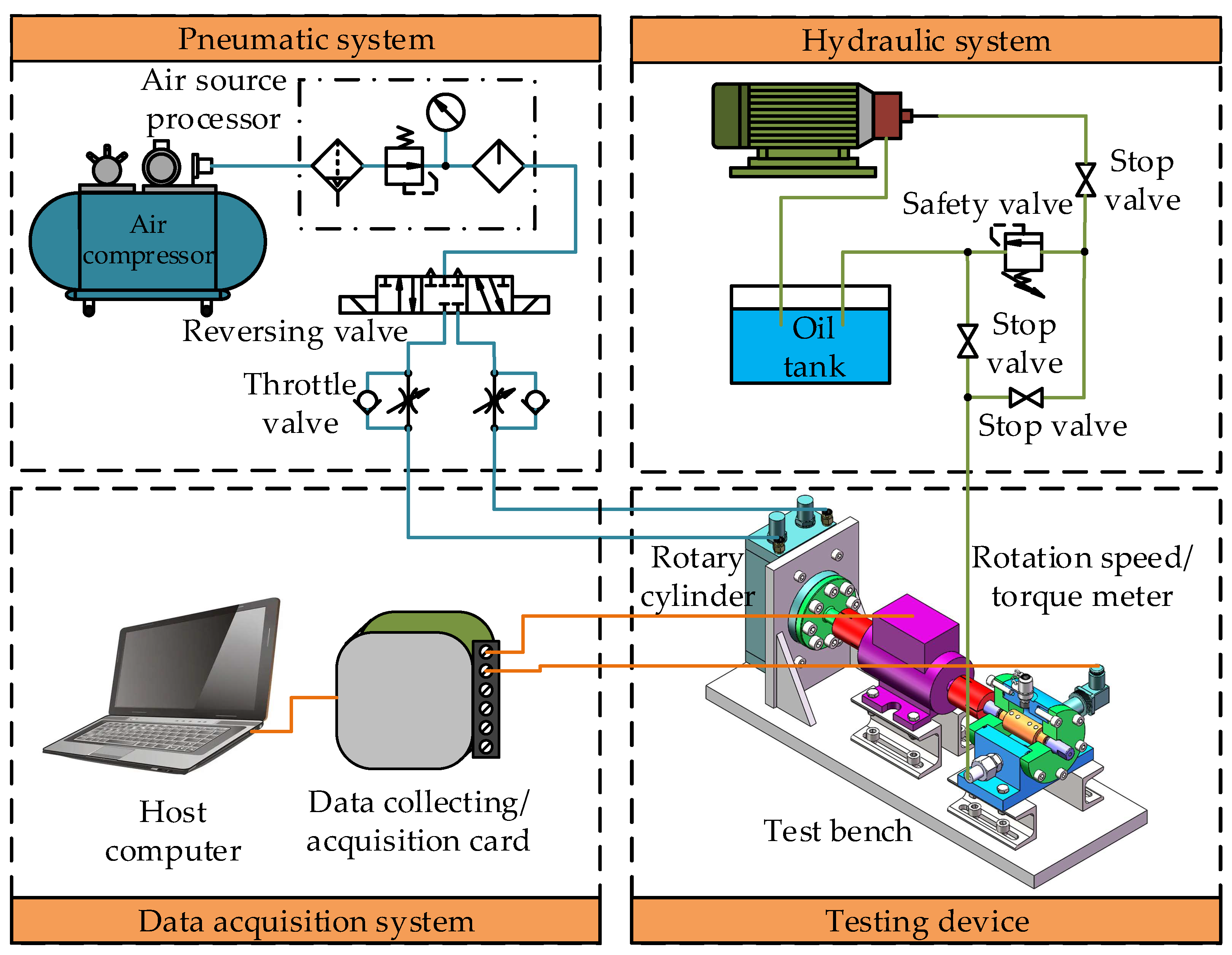
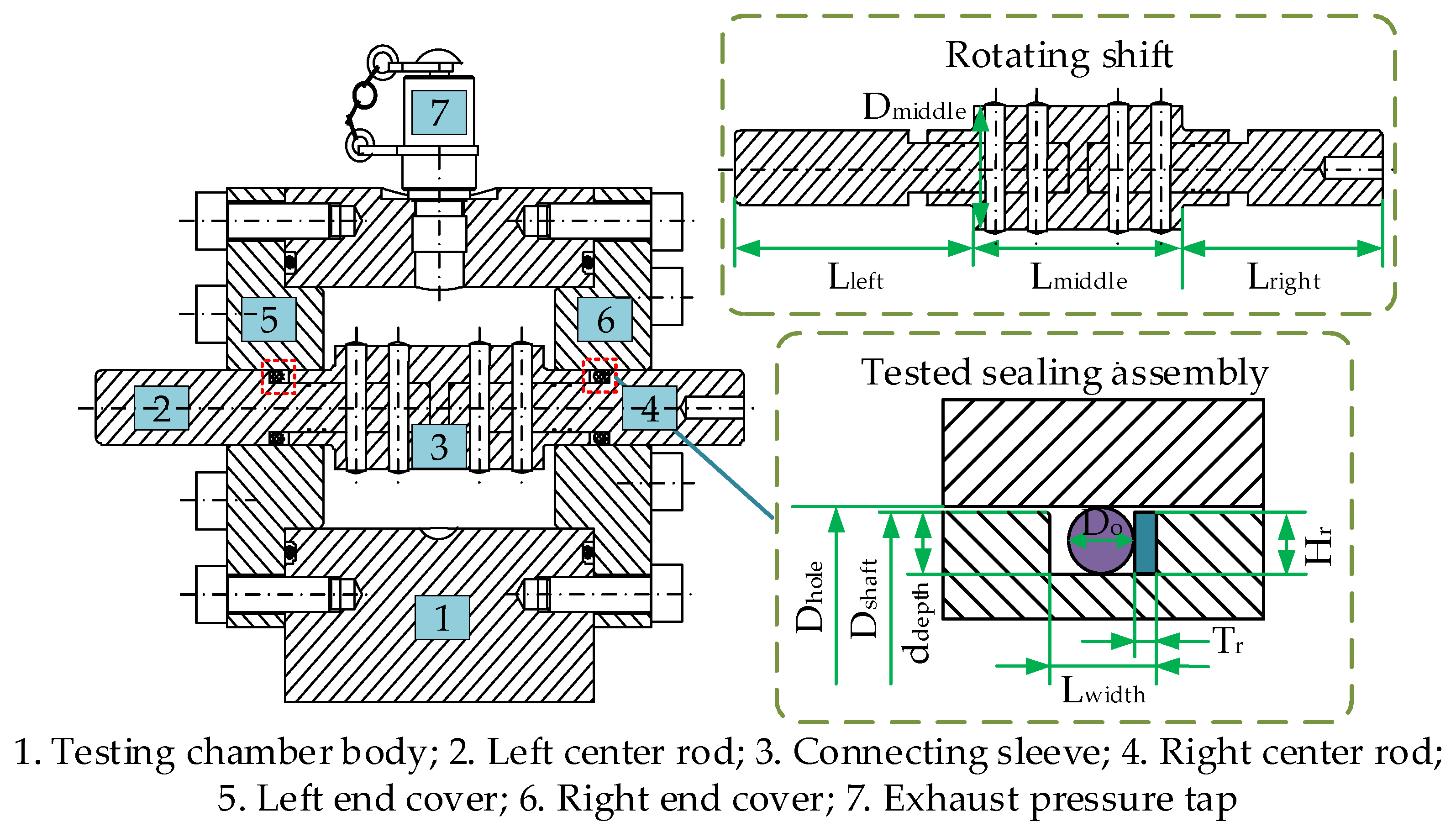
2.1. Design of the Experiment System

The friction and wear experiment system of the reciprocating rotary seals was set up in this study and the working principle of the experiment system is shown in Figure 1. The main parameters of the system are shown in Table 1. The system is mainly composed of a pneumatic system, hydraulic system, testing device, and data acquisition system. The pneumatic system provides high-pressure gas to drive the rotating cylinder movement, which can provide a smooth reciprocating rotating motion for the sealing assembly mounting shaft. The rotation speed of the rotating cylinder can be controlled by adjusting the throttle valve and the rotation angle can be controlled by adjusting the adjusting knob in the rotating cylinder, which can simulate the motion of the reciprocating rotating seal under different working parameters. The hydraulic system provides the working pressure for the seal assembly. A 10# aviation hydraulic oil was used in the hydraulic system. The constant pressure variable pump was used as the hydraulic source. When the system pressure reaches the pressure set point, the output flow of the hydraulic pump decreases, which can maintain the pressure stability of the test system and avoid the waste of energy. The oil temperature in the hydraulic tank can be monitored in real time. The hydraulic system uses an air-cooled radiator to keep the oil temperature near the set value. The testing device mainly includes a rotary cylinder, revolution speed/torque meter, and test chamber. As shown in Figure 2, the test chamber is used to install the seal assembly with two pairs of combination seals. The combination seals consist of a retaining ring with Polytetrafluoroethylene material and a rubber ring with nitrile rubber material. The main sizes of the seal and the rotating shaft are shown in Table 2 and Table 3. The data acquisition system consists of a data acquisition card and a host computer, which can collect the pressure and speed torque signals in real-time during the experiment process.

2.2. Experiment Process and Scheme

2.2.1. Experiment Process

Before the experiment, an ultrasonic cleaner was used to clean the seal components in alcohol for 20 min and the seal components were dried in natural air. An electronic balance with a precision of 0.1 mg was used for weighing. Each sample was weighed 3 times and the average value was taken as the weight value. The surface of the samples was observed by laser confocal microscope and scanning electron microscope.
When the experiment started, the air compressor was turned on in advance. The pneumatic throttle valve and the limit nut of the rotating cylinder were adjusted to make the rotating cylinder rotate according to the specified reciprocating frequency and rotation angle. The tested seal assembly was installed in the experiment device. The hydraulic oil temperature was kept at 35 ± 2 °C during the experiment. The hydraulic pump was turned on and the system pressure was adjusted to the specified pressure. The experiment time, working pressure, and speed torque signals were recorded in real-time in the experiment process.

2.2.2. Experiment Scheme

In this study, the friction and wear characteristics of hydraulic rotary seal components are obtained by friction and wear experiment. The friction characteristics of the seal components can be obtained in a shorter experiment time and the wear characteristics need a longer experiment time, the two experiments were carried out separately. The friction characteristic experiment was used to obtain the friction characteristics of the seal components under different working parameters. Each experiment was operated for 10 min. It can ensure that the friction characteristics of the seal assembly were obtained under the same wear degree due to the short experiment time. The experiment scheme is shown in Table 4.
The wear experiment is used to obtain the seal assembly’s wear and tribological evolution characteristics. The same experiment period was specified. When an experiment period was finished, the quality change in the seal assembly before and after the experiment period was calculated and the wear loss can be measured in each experiment period. When the experiment time reached the experiment period, the seals were torn down, cleaned, weighed, and observed on the surface. After these steps, the seals were once again installed in the original position for the next period of the experiment. The experiment had finished when the number of measurements had been completed. The wear characteristic experiment scheme is shown in Table 5.
In order to obtain the time-varying law of the friction characteristics of seals under a long-time experiment, a group of tested components was tested for 250 h.

3. Analysis and Discussion

3.1. Friction Characteristics

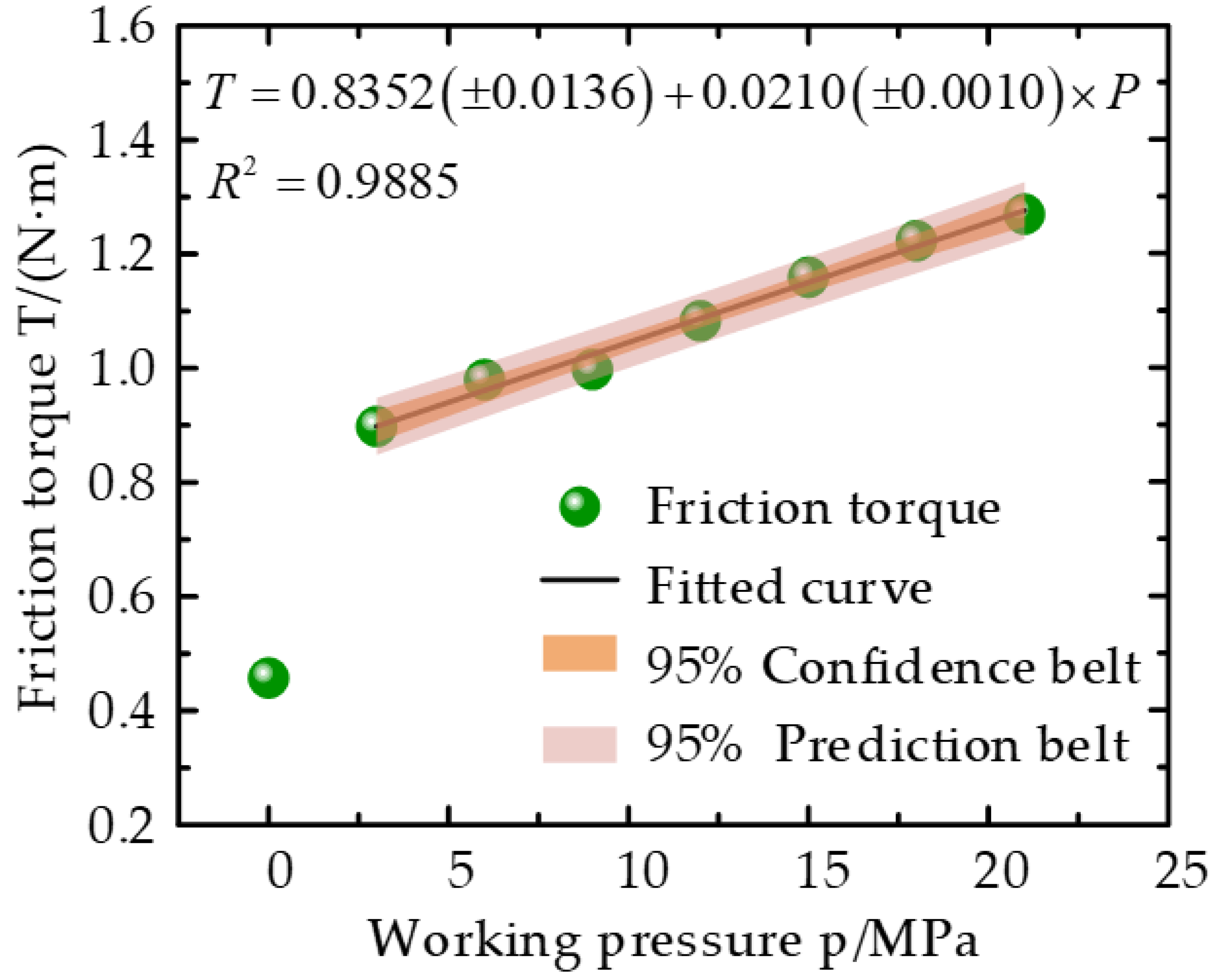
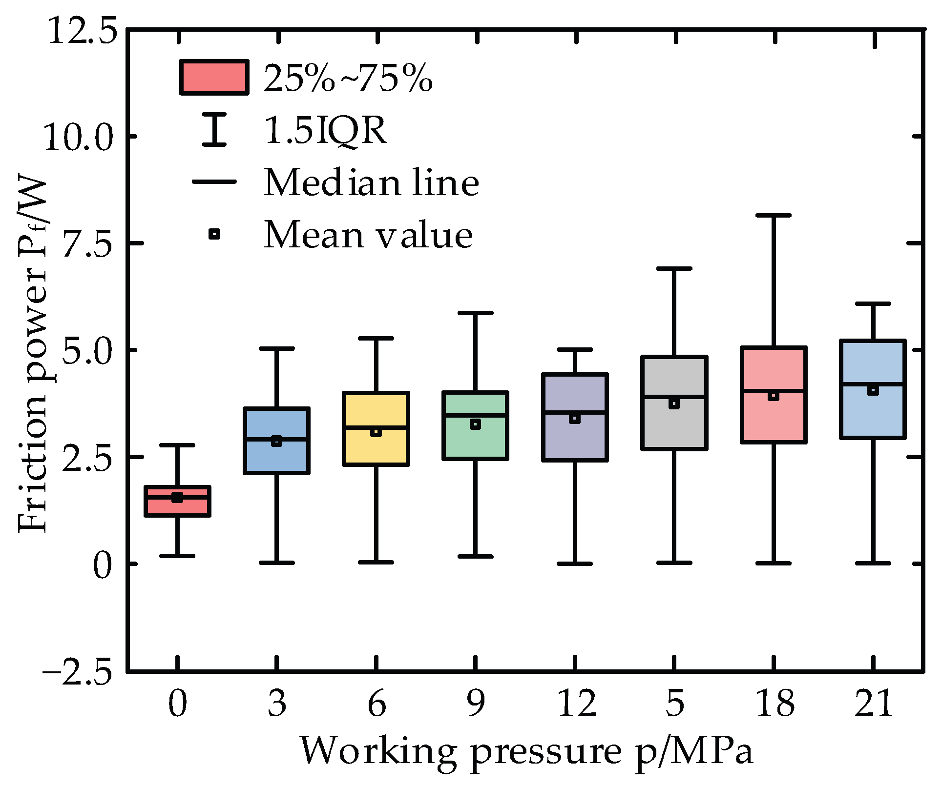
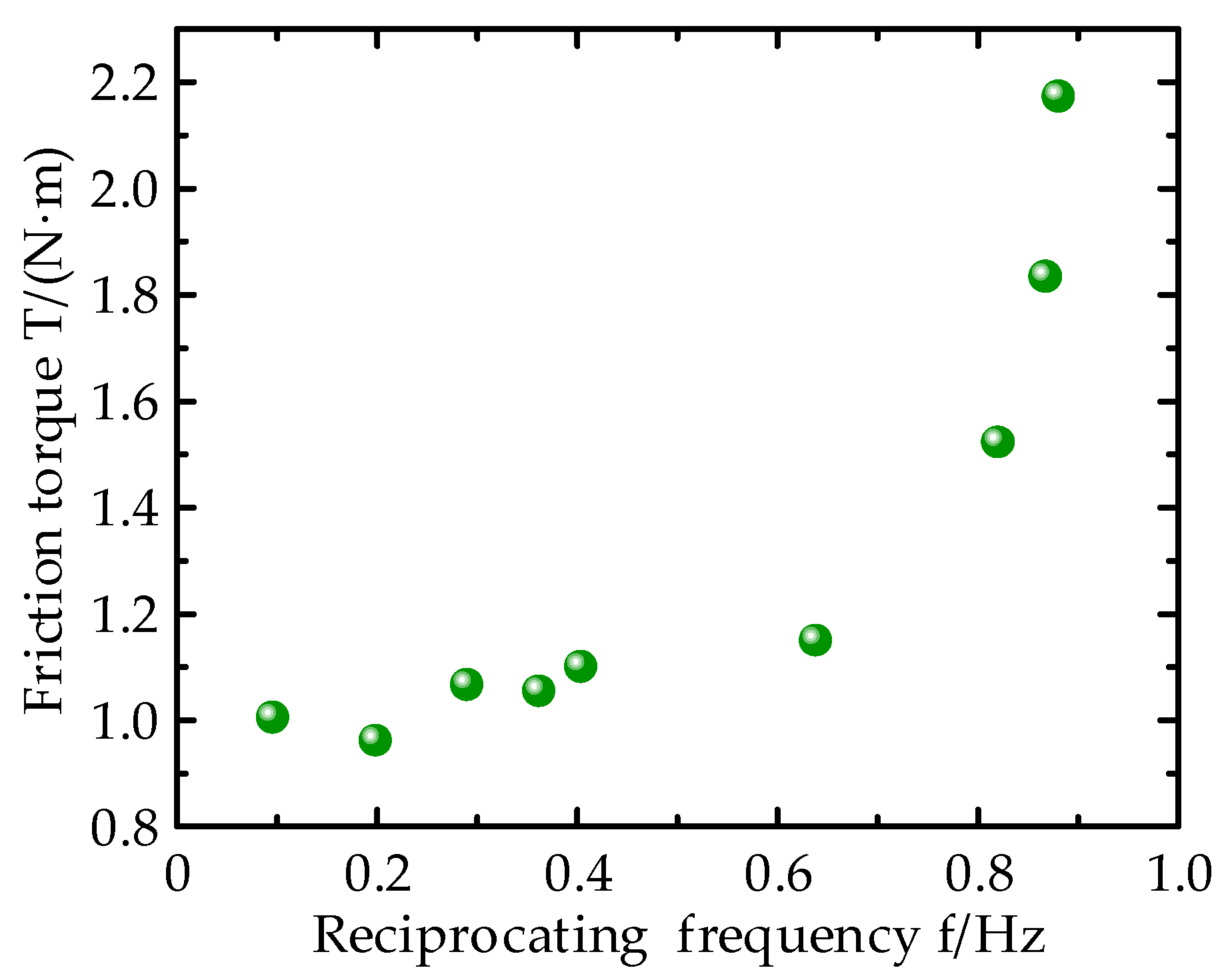
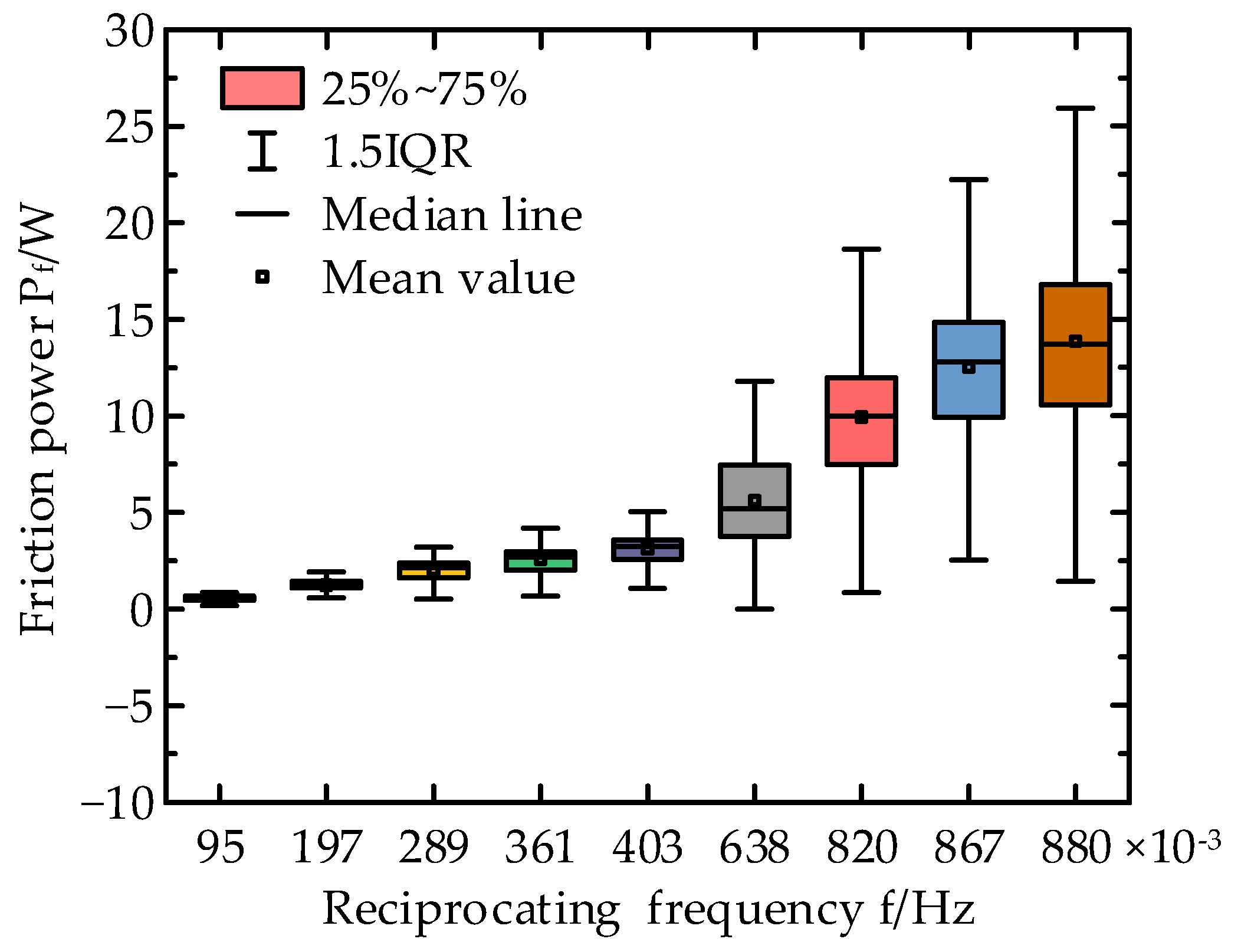
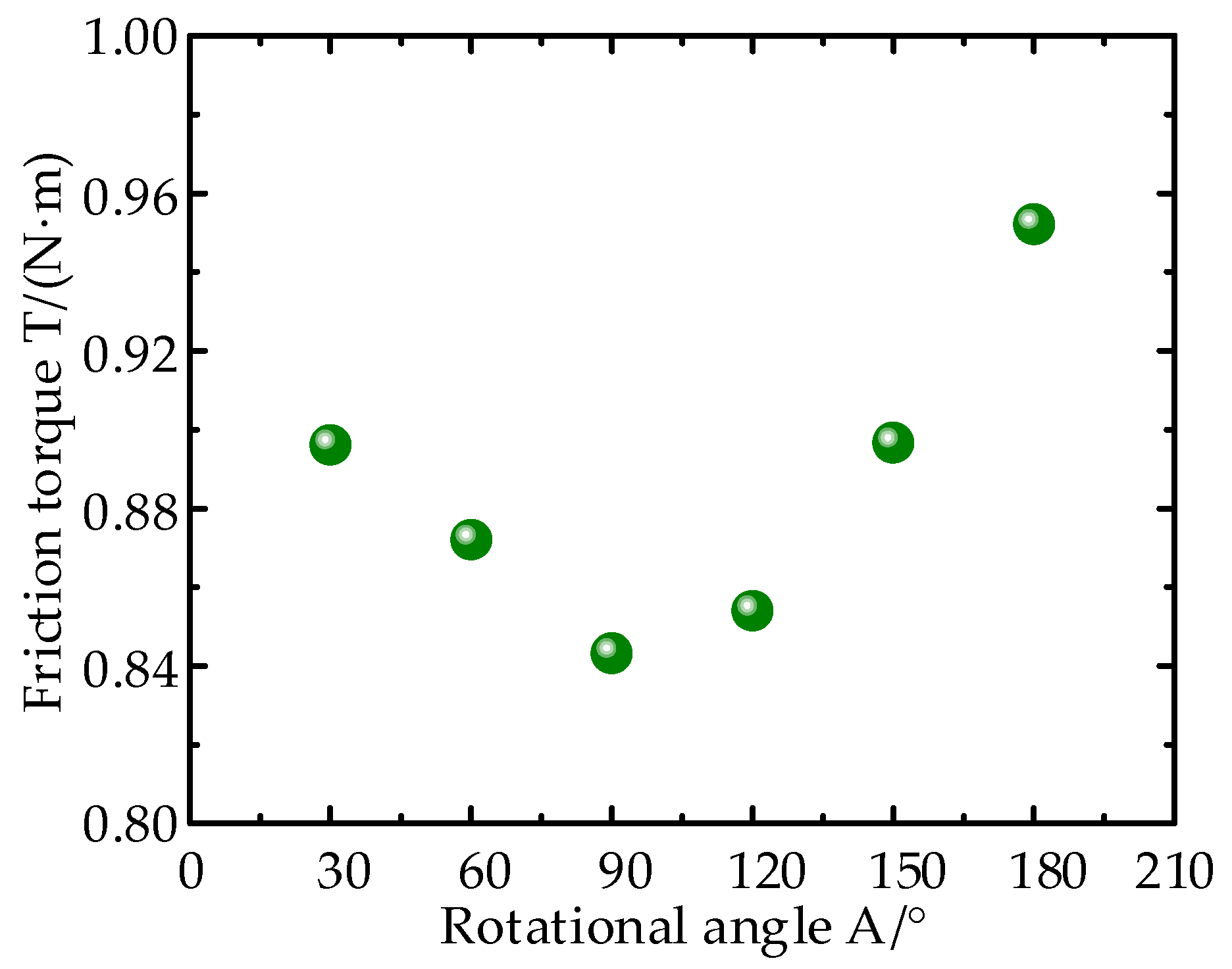
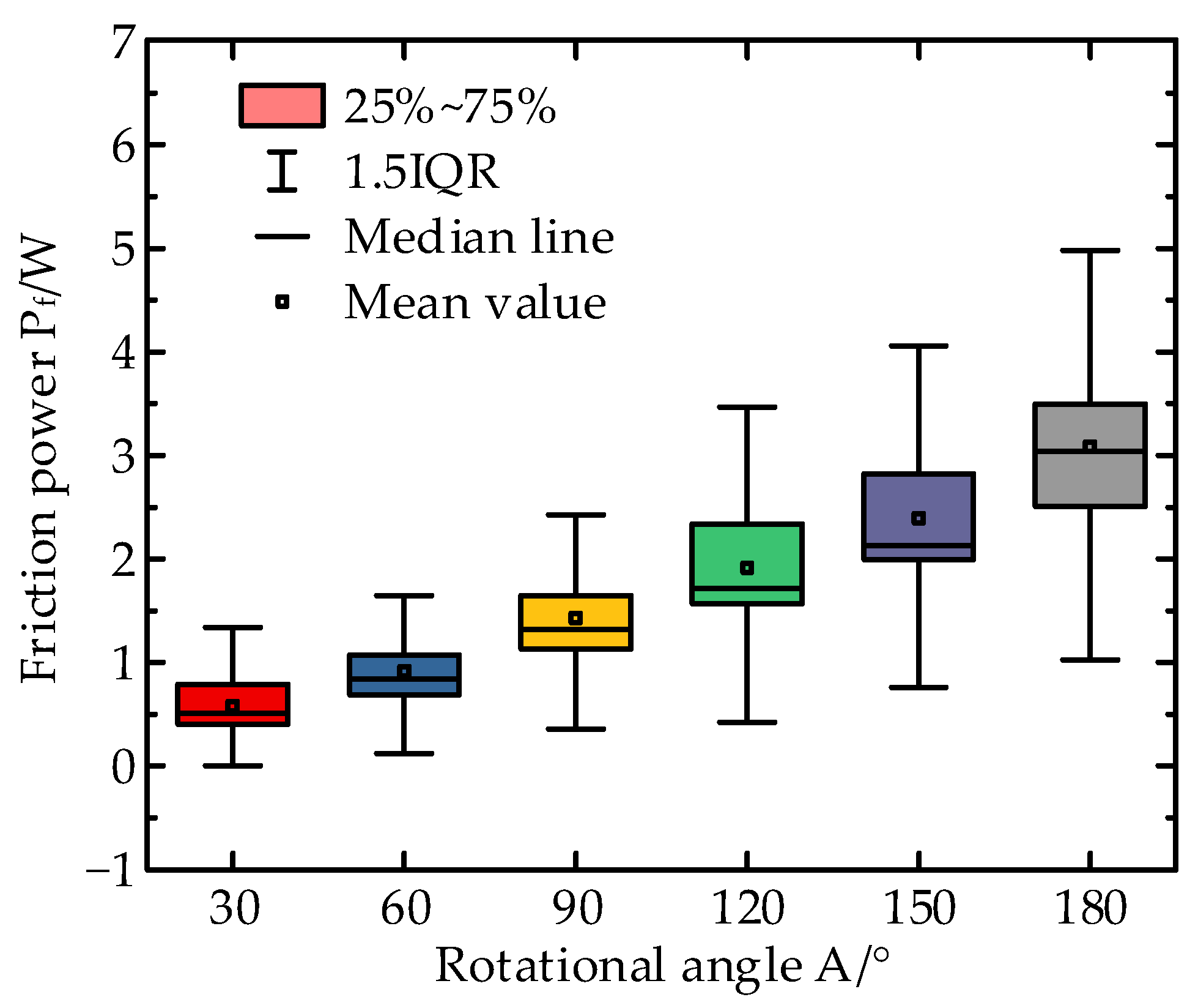
3.1.1. Friction Characteristics under Different Working Parameters

The reciprocating frequency is 0.5 Hz and the rotation angle is 180°, the rotational speed curve with time is shown in Figure 3. It can be seen from Figure 3 that when the cylinder began to work, the rotating shaft speed increased rapidly and then fluctuated within a certain range. When the cylinder rotated in reverse, the rotational speed of the rotating shaft also showed the same change. It is worth noting that Figure 3 records the raw data of the revolution speed/torque meter, measurement error is also a cause of data fluctuation. The frequency spectrum of rotational speed was analyzed and the spectrum map is shown in Figure 4. It can be seen from Figure 4 that a peak appeared at 0.5 Hz, which was the same as the reciprocating frequency of the experiment.
The reciprocating frequency is 0.5 Hz and the rotation angle is 180°, the friction torque curves with time under the pre-compression condition (P = 0 MPa) and rated condition (P = 21 MPa) are shown in Figure 5. The speed of the rotating shaft was relatively slow and the mass of the rotating shaft was small, so the effect of the moment of inertia was ignored during data processing. The matching form of the rotating shaft and shaft hole is gap matching, which means there is no additional friction torque without the installation of seals. Therefore, the torque measured by the revolution speed/torque meter is the friction torque of the seals. It can be seen from Figure 5a that in the pre-compression condition, when the center shaft began to rotate, the frictional torque increased rapidly. With the progress of rotational motion, the friction torque fluctuated within the range of 0.38~0.6 N·m. Then, the center shaft rotated in reverse and the friction torque dropped to a negative value and fluctuated in the range of −0.38~−0.8 N∙m. It can be seen from Figure 5b that in the rated condition, the frictional torque increased rapidly at the beginning of rotation and maintained around 1.4 N·m during rotation. Compared with the pre-compression condition, the friction torque fluctuation of the seal assembly under the rated condition was smaller.
The frequent motion and motionless state of the reciprocating rotary seals appeared when it was working, so the friction power is also an important embodiment of its friction characteristics. The change curve of the friction power of the reciprocating rotary seals with time under pre-compression and rated conditions is shown in Figure 6. It can be seen that the friction power of the seals has strong fluctuation under the pre-compression condition and rated condition. This is because the speed of the central shaft would change abruptly in the starting and stopping stages, resulting in friction power fluctuations. It is worth noting that the sampling frequency is 10 data per second in the experiment. Therefore, the data in Figure 6 have discreteness. Especially at the moment when the cylinder was reversed, the speed should be zero, the friction power should also be correspondingly zero. However, in Figure 6, the friction power value has a low zone and does not reach 0.
The monitoring data of 10 min were selected and the absolute value of torque was calculated first. The torque was calculated by averaging the torque value. Figure 7 shows the variation curve of the mean friction torque of the sealing component under different working pressures. It can be seen from Figure 7 that the sealing component’s friction torque is small under the pre-compression working condition. However, when the working pressure increases from 0 MPa to 3 MPa, the friction torque of the sealing component suddenly increases. With the increase in the working pressure, the friction torque presents a linear increase trend. It can be seen from the linear fitting equation and goodness of fit R2 that there is a good linear correlation between the working pressure and the friction torque. In pre-compression working conditions, there is a small contact area and contact pressure between the sealing component and the contact component, which makes the friction torque of the sealing component smaller. When the oil pressure is loaded, the rubber ring deforms under the action of high-pressure oil [26,27,28] so that the contact area between it and the inner wall of the sealing hole rapidly increases, which is the main reason for the sudden increase in friction torque. Later, with the increasing of the oil pressure, the contact area between the rubber ring and the inner wall of the sealing hole did not change greatly, but the contact stress will linearly increase with the oil pressure, so that the friction torque and the working pressure also showed a linear change relationship.
Power is used to characterize the rate of energy conversion and friction power is used to characterize the rate of kinetic energy dissipation during the friction process. In the process of friction, kinetic energy is converted into internal energy and wear occurs at the contact interface. The greater the friction power, the more intense the friction process, resulting in a faster wear rate [29,30]. The reciprocating frequency is set at 0.5 Hz and the rotation angle is set at 180°. The boxplot of the friction power of the sealing assembly with different working pressures is shown in Figure 8. It can be seen from Figure 8 that the sealing component’s friction power increases with the increase in working pressure. In the pre-compression condition, the friction power of the sealing component is small and the range of value change is small. When the high-pressure oil is worked, the mean value of the friction power of the sealing assembly increases and the variation range of the friction power also increases slightly with the increase in the working pressure. At each test point, the mean friction power of the sealing assembly is 1.63 W, 3.01 W, 3.24 W, 3.42 W, 3.57 W, 3.93 W, 4.14 W, and 4.26 W, respectively. The mean friction power shows a linear increasing trend with the increase in working pressure. This phenomenon indicates that the wear rate of the reciprocating rotary seal will be fast under high working pressure.
Figure 9 shows the relation curve of the mean friction torque of sealing components with different rotation frequencies under 21 MPa working pressure and 180° rotation angle.
It can be seen from Figure 9 that when the reciprocating frequency increases from 0.095 Hz to 0.638 Hz, the friction torque increases slowly. The friction torque increases from 1.0046 N·m to 1.1494 N·m with an increase rate of 14.41%. When the reciprocating frequency increases from 0.638 Hz to 0.880 Hz, the friction torque increases rapidly. The friction torque increases from 1.1494 N·m to 2.1728 N·m with an increase rate of 89.02%. The friction torque is mainly generated by the friction between the rubber ring and the contact part. The rotation speed will increase with the increase in reciprocating frequency. When the rotation speed increases, the friction force between the components becomes larger due to the viscous friction of the rubber. This is consistent with the results in the reference [14,16]. When the reciprocating frequency is greater than 0.638 Hz, the friction torque value will increase rapidly. The reason for this phenomenon may be that when the rotation speed of the rotating shaft was slow, the rotating shaft would not drive the retaining ring or rubber ring movement. And when the rotation speed of the rotating shaft was too fast, the rotating shaft drove the retaining ring or rubber ring to movement. It makes the relative motion state between the retaining ring, the rubber ring, and the contact components change. This causes more components to move relative to each other, which increases the friction between the rotating shaft and the contact component.
The working pressure is set at 21 MPa and the rotation angle is set at 180°, the boxplot of the friction power of the sealing assembly under different rotation frequencies is shown in Figure 10. It can be seen from Figure 10 that the mean friction power of the sealing component increases with the increase in reciprocating frequency, this change is particularly obvious when the reciprocating frequency is greater than 0.638 Hz. At each test point, the mean friction power of the sealing assembly is 0.59 W, 1.30 W, 2.13 W, 2.71 W, 3.29 W, 5.89 W, 10.41 W, 13.12 W, and 14.54 W, respectively. Therefore, the mean friction power will show exponential correlativity with the reciprocating frequency. The variation range of friction power also increases sharply with the increase in reciprocating frequency. This phenomenon indicates that the wear rate will become fast when the reciprocating frequency is large.
The working pressure is set as 21 MPa and the reciprocating frequency is set as 0.5 Hz, the mean friction torque of the sealing component under different rotation angles is shown in Figure 11. It can be seen from Figure 11 that there is no monotone variation between the frictional torque and the rotation angle. When the rotation angle increases from 30° to 90°, the frictional torque decreases; when the rotation angle increases from 90° to 180°, the frictional torque increases. When the rotation angle increases from 30° to 180°, the friction torque fluctuates in the range of 0.84~0.96 N·m. Compared with working pressure and reciprocating frequency, rotation angle has less effect on friction torque.
The working pressure is set as 21 MPa and the reciprocating frequency is set as 0.5 Hz, the boxplot of the friction power of the sealing assembly under different rotation angles is shown in Figure 12. It can be seen from Figure 12 that the mean value and variation range of friction power increase with the increase in rotation angle. The reason for this phenomenon is that at the same reciprocating frequency, the rotation speed increases with the increase in the rotation angle, which gives rise to the increase in friction power. This indicates that at the same reciprocating frequency, the greater the rotation angle of the rotary seal assembly, the faster the wear rate.

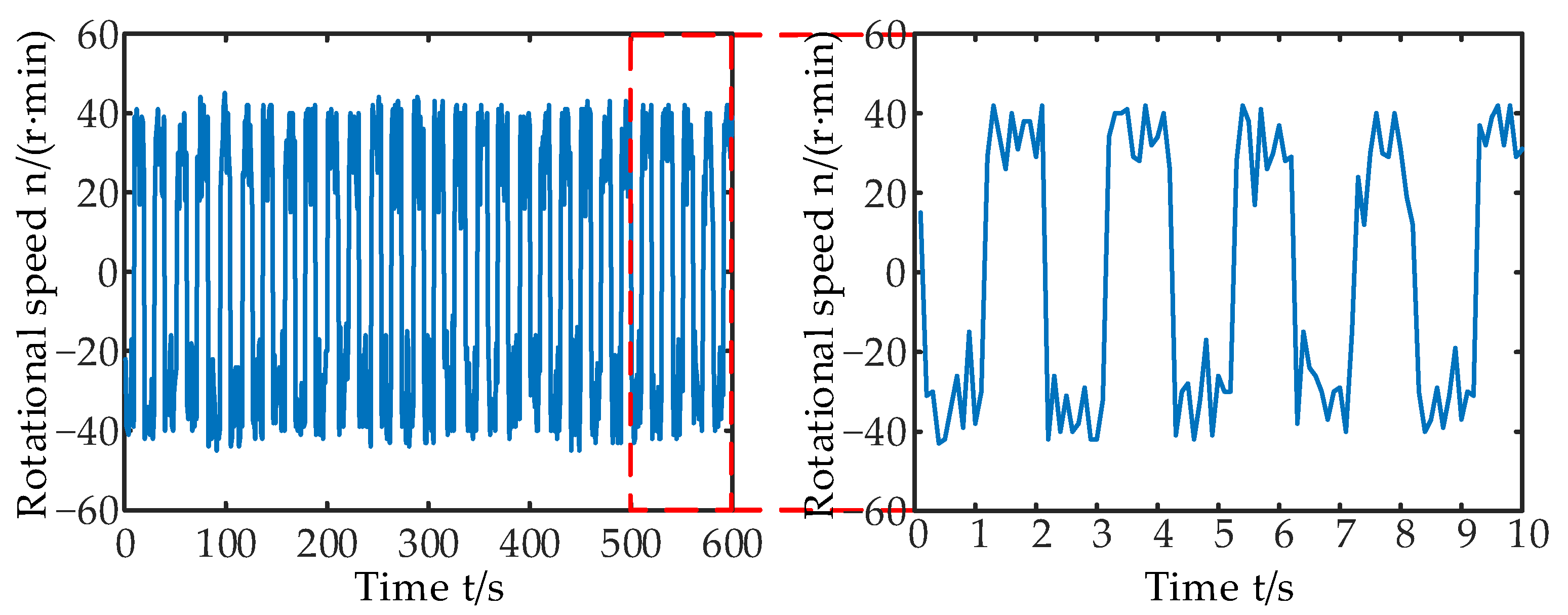
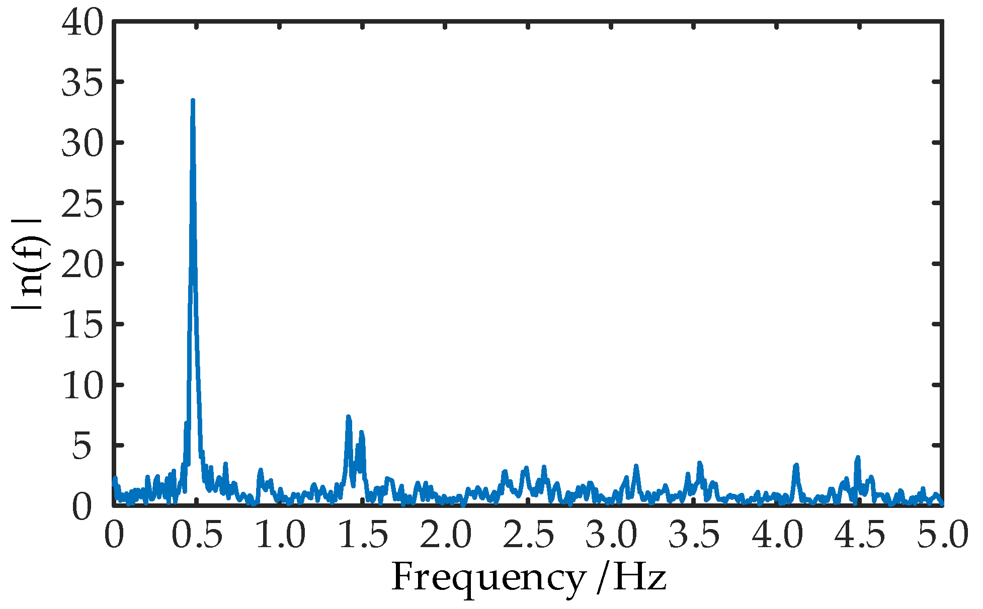
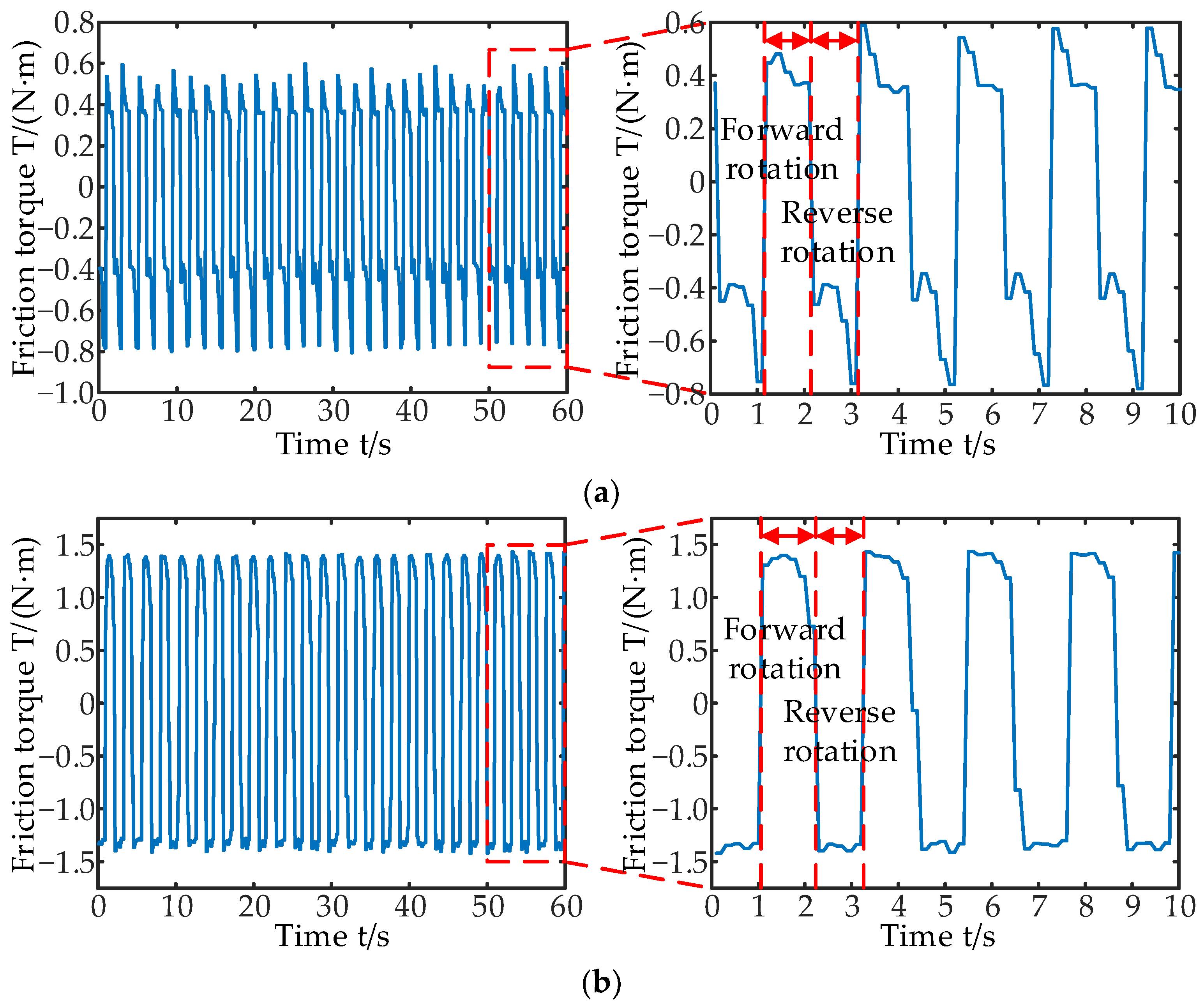
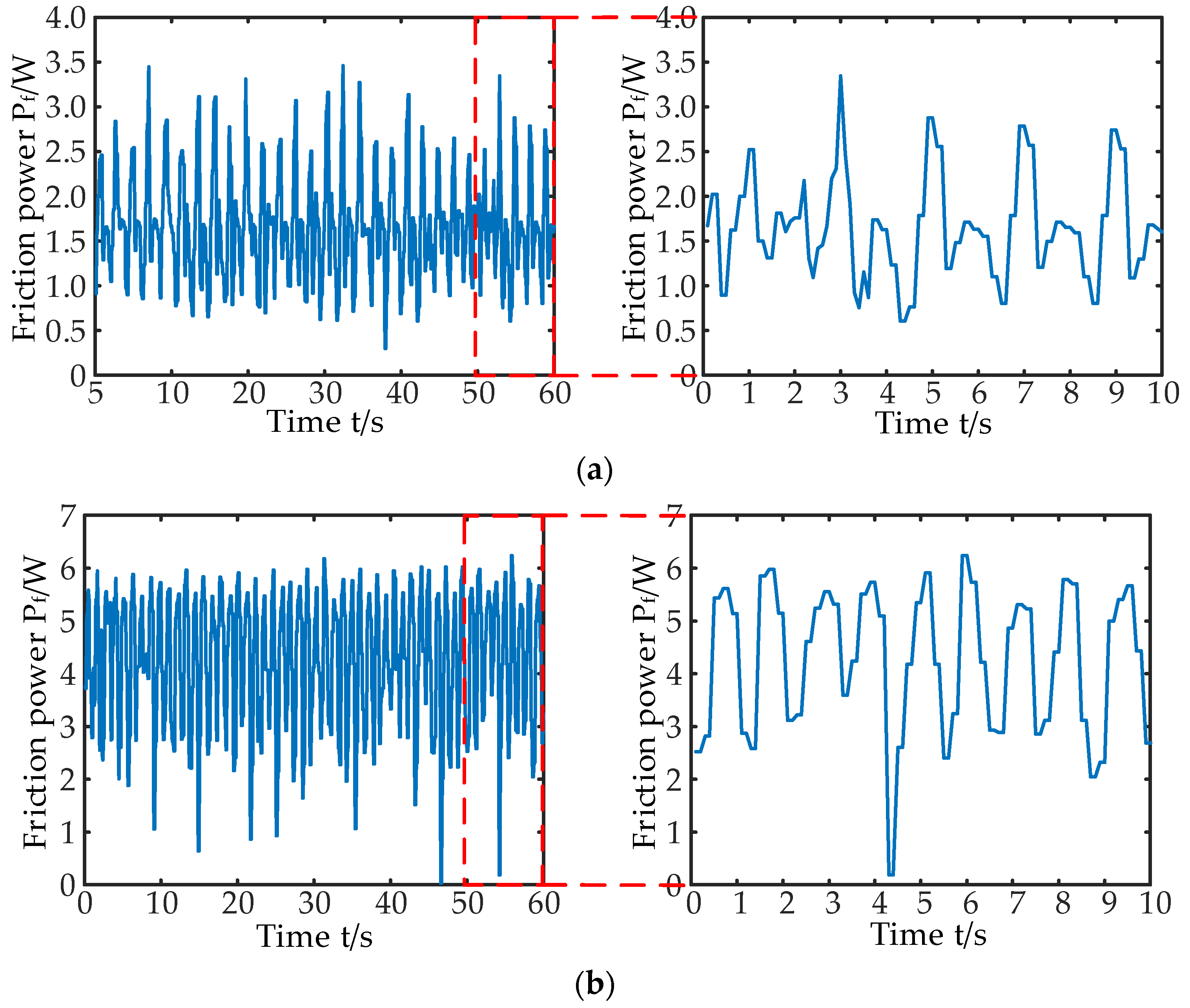
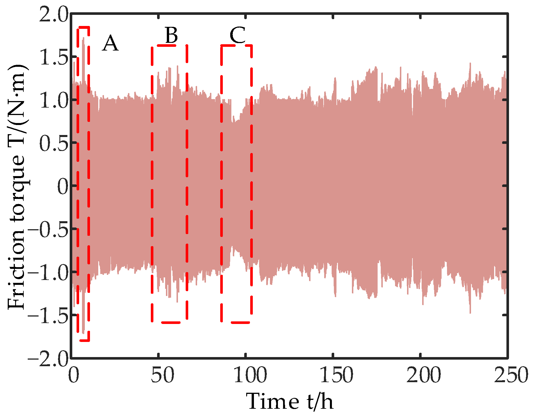
3.1.2. Time Evolution Characteristics of Friction Torque

The working pressure is set as 21 MPa, the experiment time is set as 250 h, and the torque change of the seal component is shown in Figure 13. It can be seen from Figure 13 that the friction torque of the sealing component is high volatility and has different change characteristics in different experiment periods, which reflects the change in the contact state and wear state of the sealing component. In the same tribological system, there is a positive correlation between friction coefficient and wear rate [6] so the wear state can be identified by the friction torque. As shown in Figure 13, an abrupt change in torque occurs in region A, combined with the observation of the experiment device in the experiment process, a large amount of debris in the gap between the rotating shaft and the shaft hole can be found. The phenomenon indicates that a severe wear process occurred in the retaining ring during this period and the friction torque increased due to the existence of wear debris. With the continuous relative rotation between the shaft and the shaft hole, the wear debris is gradually triturated and squeezed out of the gap. At this period, the friction torque decreases and the contact state will be maintained for a long time. The friction torque increases in region B and the friction torque fluctuates greatly. Black impurities were observed on the outside of the seal gap during this experimental period. This indicates that the rubber ring was more severely worn during this period. The reason for this phenomenon may be that the rubber material was squeezed into the gap between the shaft and the shaft hole, resulting in an increased friction torque. The friction torque decreases in region C. No new debris was observed during this period. It indicates that the sealing component wear rate decreased during this period. Due to the complexity of the contact state, the sealing component self-adjusted to a relatively good contact state. However, this contact state will not be maintained for a long time and the frictional torque will continue to increase or decrease with the increase in the experiment running time.

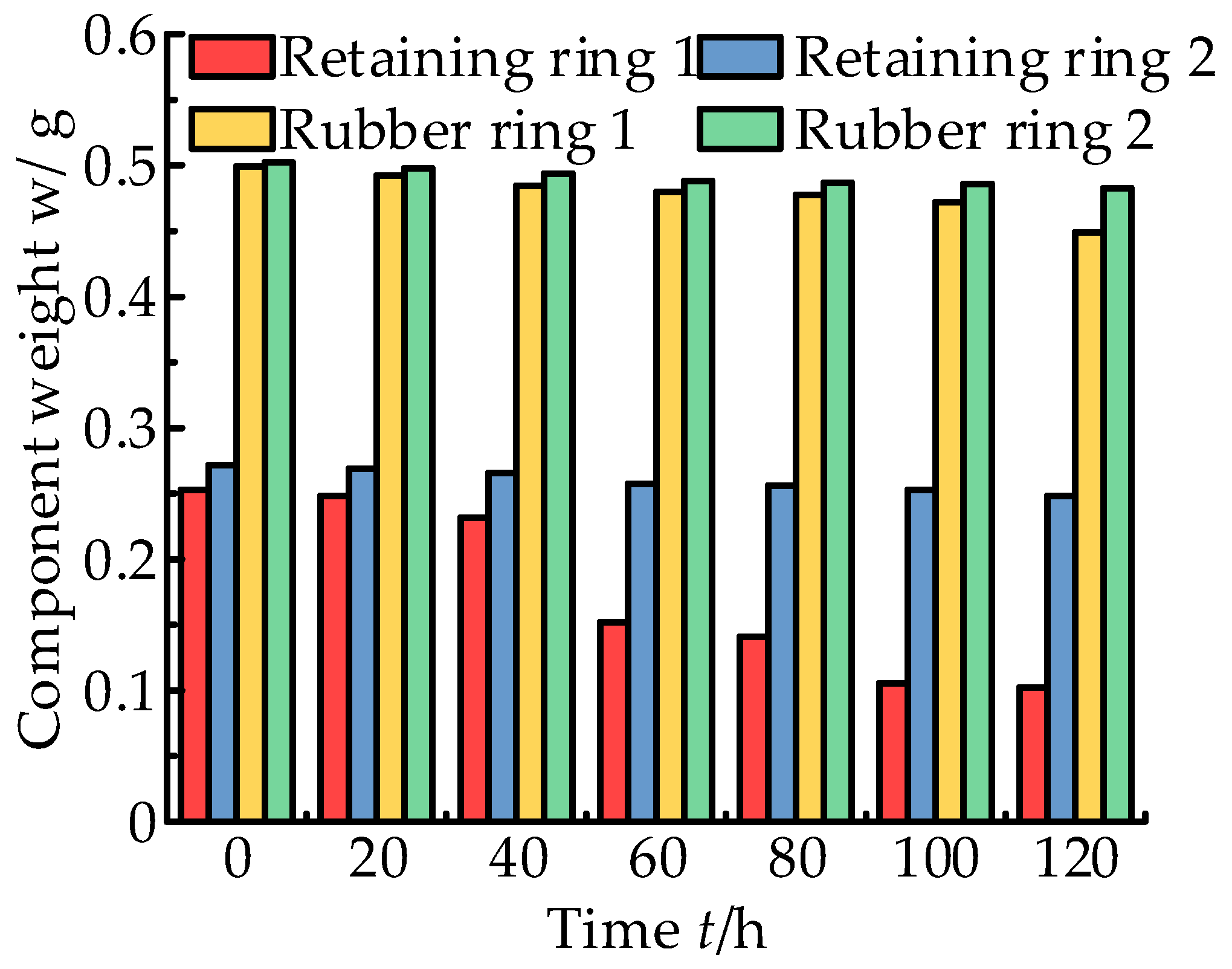
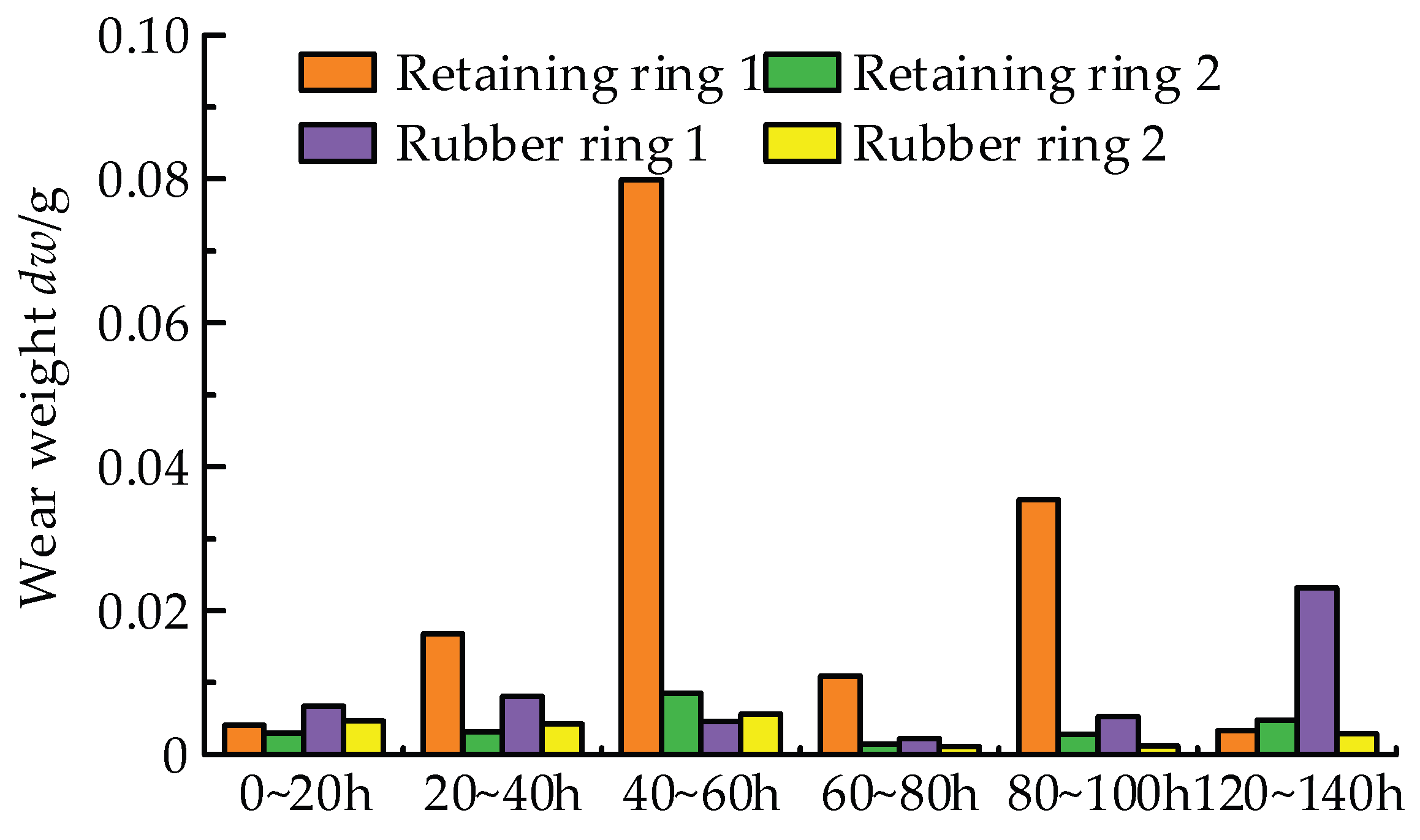
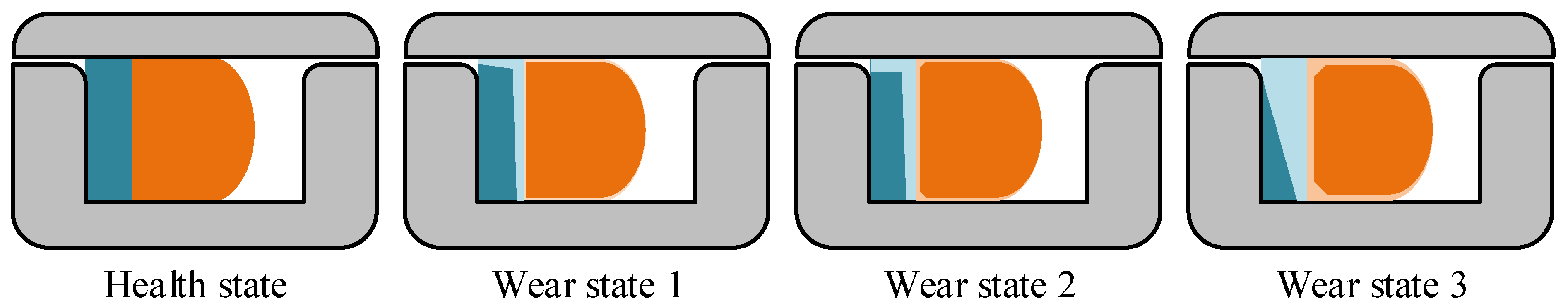
3.2. Wear Characteristics

The wear experiment was carried out in accordance with the formulated experiment scheme in Table 5 and the weight of each seal component changed with the experiment time as shown in Figure 14. It can be seen from Figure 14 that the weight of different seal components presents monotonically decreasing changes with the increase in experiment time. The weight of different seal components changes at different rates, which indicates that the wear rate of different seal components presents certain differences. Compared with the rubber ring, the difference in the wear rate of the retaining ring is big. This is mainly because the retaining ring is the rapid-wearing component under the reciprocating rotating motion pattern. Due to the different contact states between the components, there would be a random relative rotation state between the retaining ring and the rubber ring. The side face of the retainer ring would appear seriously worn under the squeezing action of high pressure.
The change in part weight increment at different measurement timing is shown in Figure 15. It can be seen from Figure 15, the part weight increment has a certain randomness; that is, the wear rate is different at different experiment times. The weight increment difference of the rubber ring is small at different measurement timings and its value will fluctuate between 0.001 g and 0.008 g. The wear rate of the retaining ring has a large difference and a serious wear process occurred within the experiment time of 40~60 h. A statistical analysis and normal distribution test were carried out on the wear increment of the retaining ring and rubber ring and the results are shown in Figure 16 and Table 6. It can be seen from Figure 16a that the data are distributed on both sides of the fitted curve but there is an abnormal data point. When the abnormal data points are removed, the data points are distributed evenly on both sides of the line, as shown in Figure 16b. It indicates the data are normally distributed. The wear data of the rubber ring have good normal distribution characteristics, as shown in Figure 16c. It can be seen from Table 6 that the wear weight increment of the retainer ring and rubber ring both conform to normal distribution. The wear weight of retaining ring 1 is abnormally large within 40~60 h. Therefore, this value is considered as an outlier in the distribution test. When the abnormal wear value of the retaining ring is removed, the reliability that the retainer wear weight increment conforms to normal distribution becomes higher.

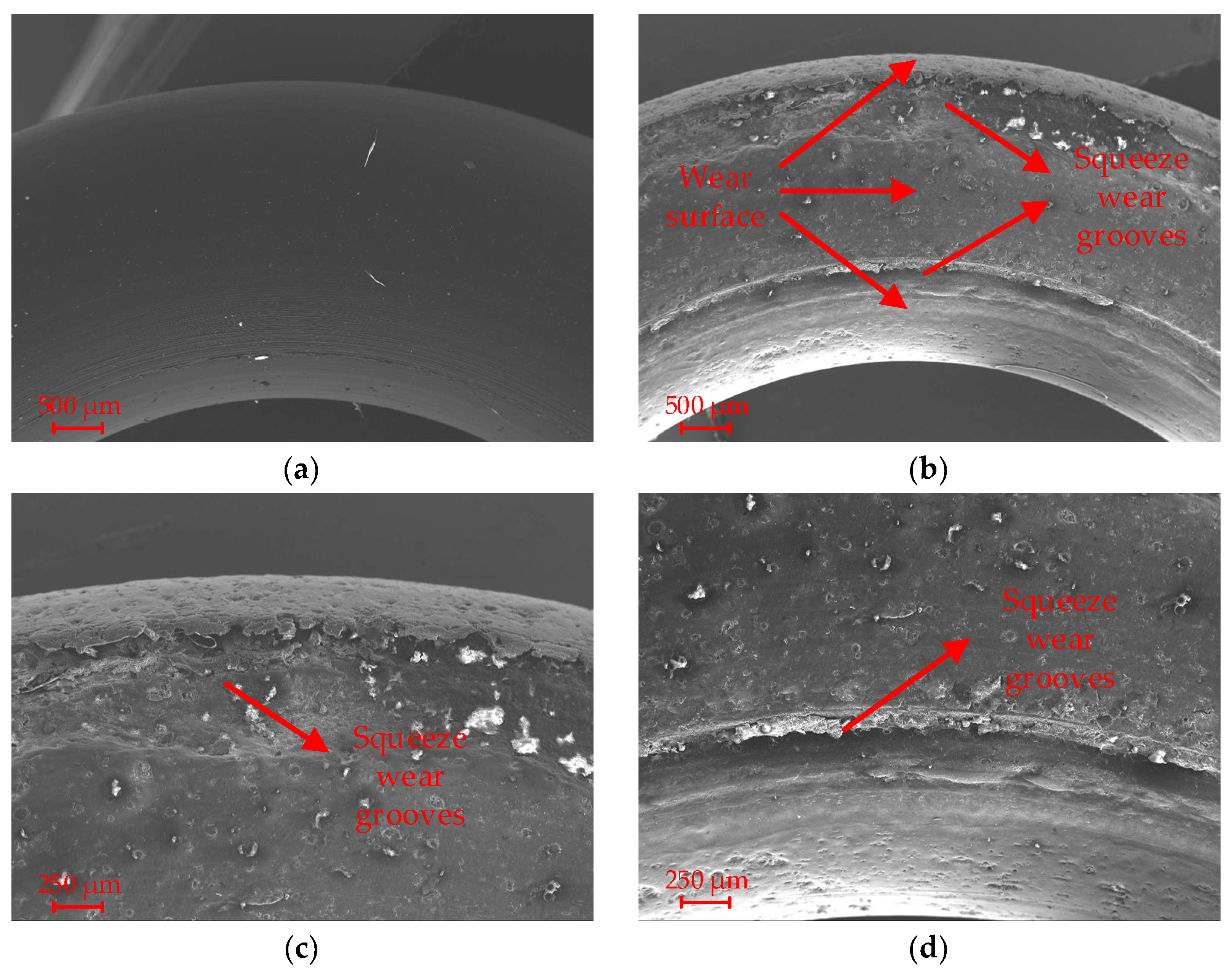
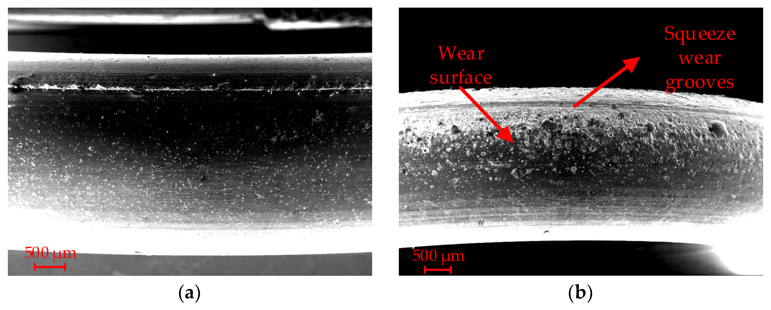
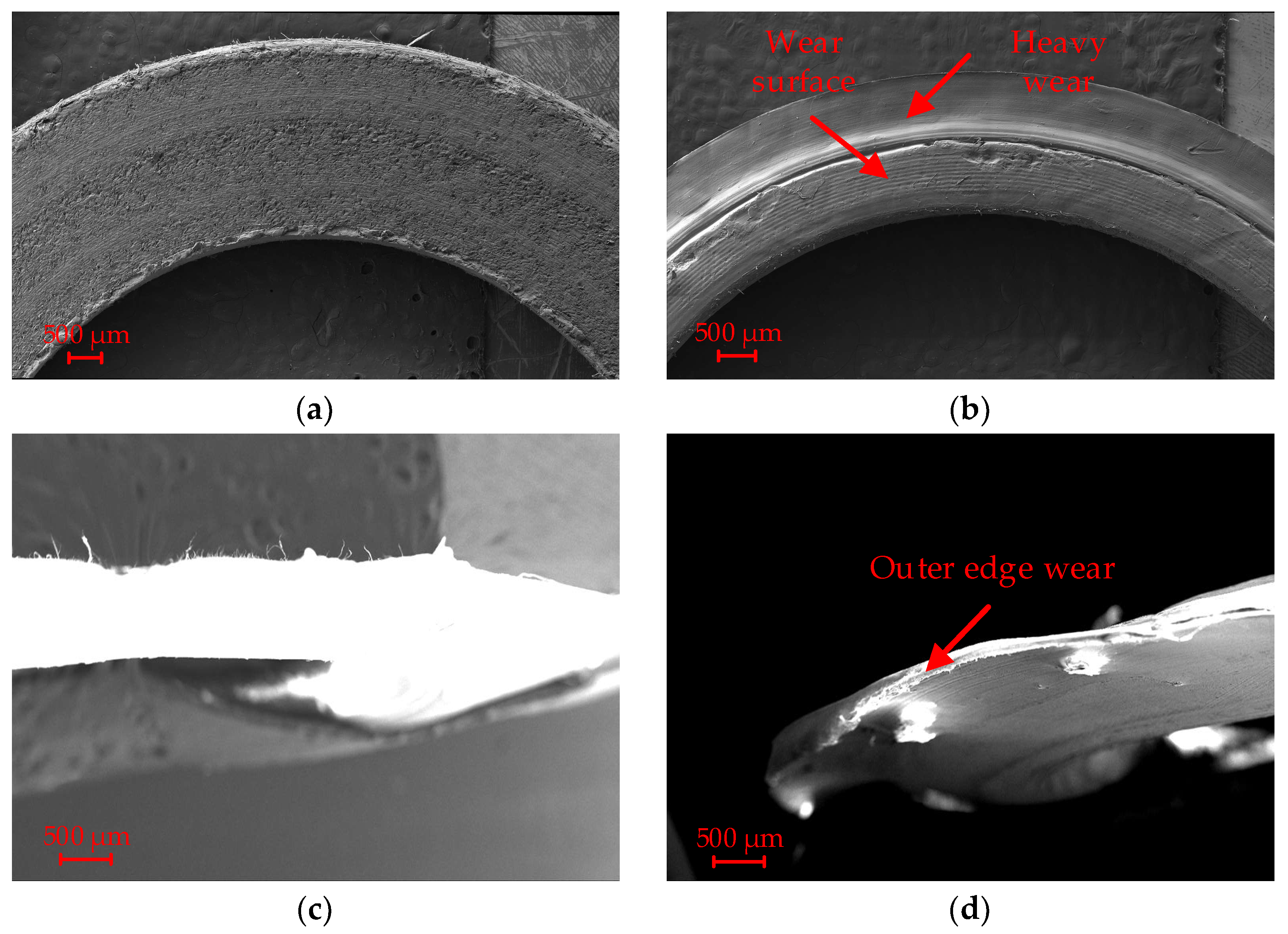
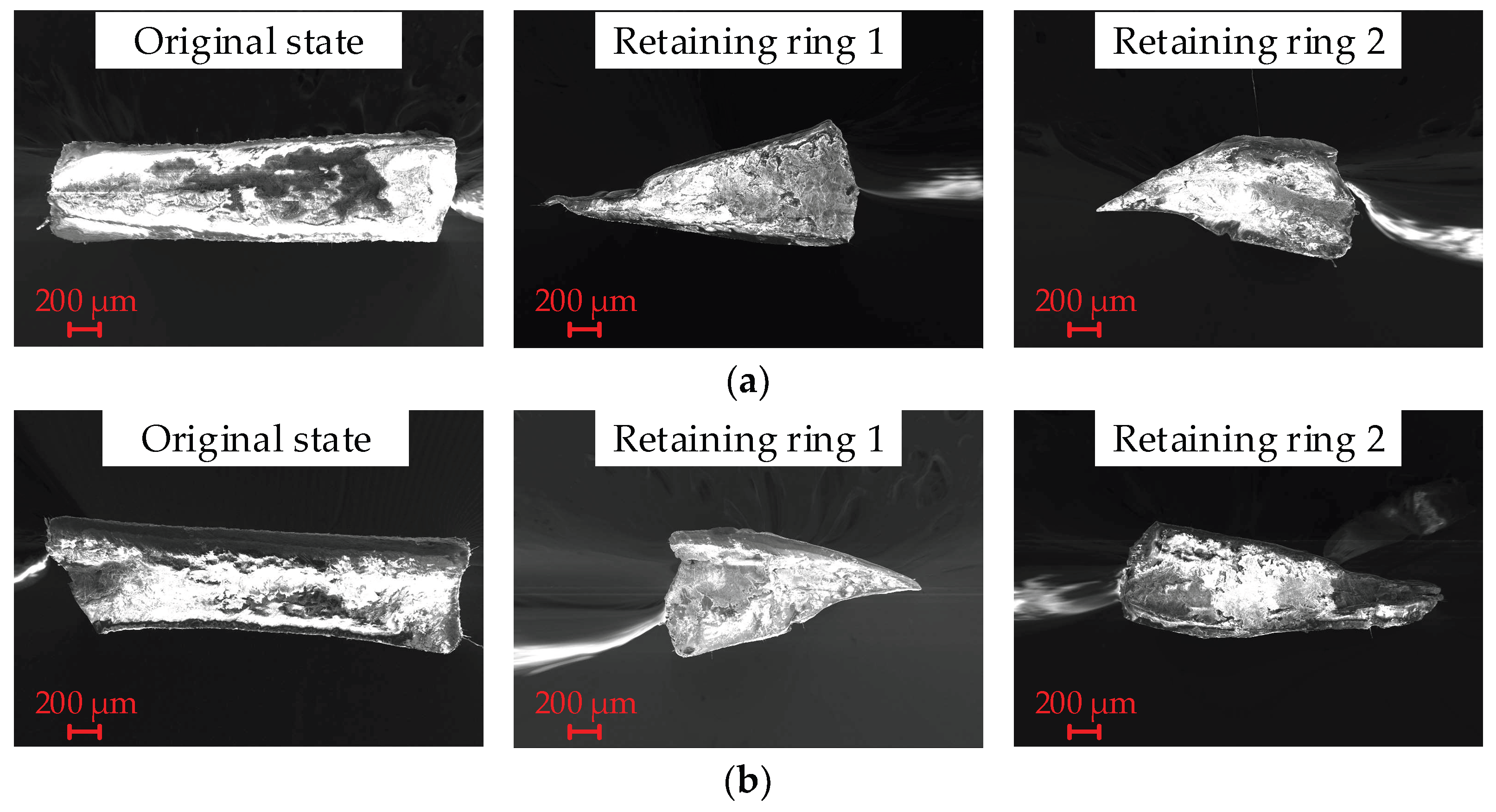
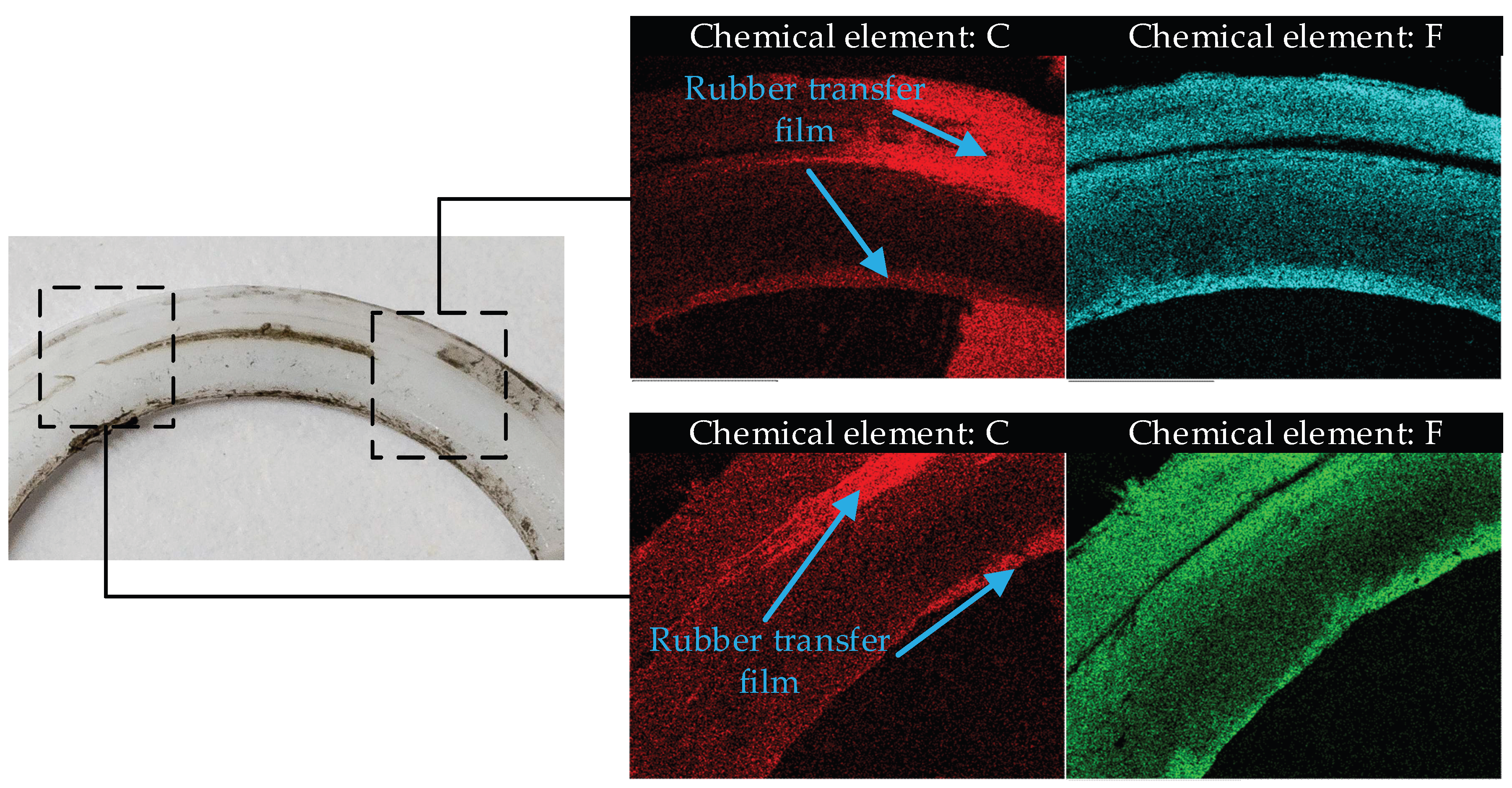
3.3. Surface Morphology

Rubber ring 1 was used to analyze the wear process and wear mechanism. The worn surface morphology of the rubber ring before and after the experiment is shown in Figure 17 and Figure 18. The wear process of the rubber ring appeared when the relative motion occurred between the retaining ring, the shaft hole surface, and the bottom surface of the seal groove. Because the wear rate of the retainer ring is faster than that of the rubber ring in the early stage experiment, the change in the morphology of the retaining ring made the rubber ring easy to squeeze into the gap between the retainer ring and the sealing hole wall. When the rubber ring moved relative to the surrounding parts, the material fell off at the clearance part. As shown in Figure 17, two wide squeeze grooves appear on the side face of the rubber ring in contact with the retaining ring. The surface wear made the roughness of the retaining ring higher, which made the wear rate at the contact surface between the rubber ring and the retaining become faster. The roughness of the shaft hole surface and the bottom surface of the seal groove is small, the wear rate of the contact part between the rubber ring and the shaft hole surface and the bottom surface of the sealing groove is slow and the wear characteristics are different. As shown in Figure 18, there are many pore structures on the top face of the retaining ring, which increases its surface roughness. When the retaining ring contacts the sealing hole wall and the bottom surface of the seal groove, the larger roughness summit increases the pore gap on its surface, which increases the risk of leakage.
The surface topography of the retaining ring before and after the experiment is shown in Figure 19. Compared with the original surface topography before the experiment, the shape and surface structure of the retaining ring have shown significant changes, the side face of the retaining has become irregular. It indicates that there is a relative movement between the retaining ring and the rubber ring. The pressure of the working oil was transferred to the retaining ring through the rubber ring, and then the pressure was transferred to the side face of the sealing groove through the retaining ring. There is a high contact pressure between the retaining ring and the rubber ring and the side face of the sealing groove. The wear of the side face of the retaining ring has occurred when the relative motion has occurred between the three parts. The wear phenomenon has appeared at two side faces of the retaining ring, it can be inferred that the retainer ring, the rubber ring, and the side face of the sealing groove may present different relative motion patterns: (1) The retaining ring and the rubber ring have the same motion pattern: The retaining ring and the rubber ring remained stationary under the friction of the sealing hole wall. At this time, the retaining ring has a relative motion to the side wall of the sealing groove, and the wear phenomenon occurred at the side face of the retaining ring closing to the side wall of the sealing groove. (2) The retaining ring and the sealing groove side have the same motion pattern: the rubber ring was driven by the friction of the sealing hole wall to produce a rotating motion, and the retaining ring remained stationary under the static friction force of the sealing groove side wall. At this time, the retaining ring has a relative motion to the rubber ring, the wear phenomenon occurred at the side face of the retainer ring closing to the side face of the rubber ring. These motion patterns may alternate due to the random variation in the contact state of each part. The retaining ring may suffer serious wear at the early stage of service.
The change in the retaining ring cross-section shape before and after the experiment is shown in Figure 20. The rectangular cross-section shape has been worn into a nearly triangular shape. Comparing two different cross-sections of the same retaining ring, it is found that the shape of different cross-sections of the retaining ring is slightly different, which indicates that the wear degree of the retaining ring at different circumferential positions is not the same. The uneven wear of the retaining ring makes the contact condition between the retaining ring and the rubber ring become worse. This will further accelerate the wear rate of the rubber ring. In fact, when the cross-section shape of the retaining ring is worn to the triangle, it has lost its sealing ability. At this time, the rubber ring may be directly squeezed into the gap between the shaft and the hole. Therefore, in the condition of reciprocating rotation movement, the retaining ring is prone to wear and failure in comparison to the rubber ring. When the retaining ring weight loses 40%, it can be considered that the retaining ring has failed.
EDS analysis of the retaining ring surface is shown in Figure 21. Carbon and fluorine are the main elements of the retaining ring. However, EDS analysis shows that these two kinds of elements have different distribution characteristics on the surface of the retaining ring. It can be seen that amounts of carbon elements appeared in some places on the surface of the retaining ring. Compared with the physical picture of the retaining ring, it can be found that black material appeared on the surface of the retaining ring at these positions. Rubber material contains amounts of carbon elements, which indicates that there was a transfer film of rubber material on the surface of the retaining ring. This phenomenon indicates that severe wear occurred between the retaining ring and the rubber ring due to the high-pressure extrusion. Therefore, limiting the relative motion between the rear ring and the rubber ring is an effective way to improve the rubber and plastic combination seal under the reciprocating rotary motion.
The wear state evolution process of the seals is shown in Figure 22. The light-colored parts of the retaining ring and O-ring in Figure 22 are the missing parts of the retaining ring and O-ring due to wear in different periods. The deformation and position of the retaining ring in Figure 22 are only for comparison of the volume change before and after wear. In the actual working process, the rubber ring will maintain contact with other components under the action of oil pressure. The relative movement between the retaining ring and rubber ring occurred in the initial experiment phase, the side face and top face of the retaining ring exhibited stress damage and wear fast under high pressure. The thickness of the retaining ring became thinner and the outline was damaged after this period of wear, as shown in wear state 1. Then, the rubber ring was squeezed into the wear area of the retaining ring. The stress in the squeeze gap of the rubber increased, and under the action of the reciprocating cyclic stress, the rubber ring material was split away and formed a wide wear band.
The surface roughness of the retaining ring increased after being worn, and the rubber ring surface contact with the retaining ring began to exhibit a more obvious wear phenomenon, as shown in wear state 2. Later, with the development of the wear process, the retaining ring appeared significant wear, and its section shape also changed from the original rectangle to a triangle. The rubber ring’s surface contact with the surrounding parts appeared uniform wear with slow speed, and the mass of the rubber ring was further reduced, as shown in wear state 3.

4. Conclusions

In this research, a series of experiments were conducted to investigate friction and wear characteristics of hydraulic reciprocating rotary seals, the specific conclusions are summarized as follows:
(1) During a rotation cycle, the friction torque value first increases rapidly, then stabilizes around a fixed value, and then rapidly decreases to zero. The friction torque increases linearly with the increase in working pressure, increases with the increase in rotation speed, decreases first and then increases with the increase in rotation angle, and the friction power increases with the increase in working pressure, rotation speed, and rotation angle.
(2) The mean value of friction torque shows a fluctuating trend during the long experiment period. When the torque changes abruptly, the friction state of the seals will change. Torque monitoring data and experimental phenomena show that there is a correlation between torque and seal wear rate. When the torque suddenly increased, the seals were in a poor contact state, and the wear rate increased.
(3) The retaining ring and rubber ring show different wear rates, the wear rate of the retaining ring was higher than that of the rubber ring.
(4) Compared with the linear motion seals and one-way rotary seals, the wear condition of the combination seal of the retaining ring and the rubber ring is different under the motion of reciprocating rotation. Under conditions of linear motion and one-way rotary motion, the retaining ring and rubber ring only have serious wear at the contact surface with the motion shaft. The reciprocating rotary seals will wear in addition to the surface contact with the rotating shaft, and serious wear will also occur at the interface between the retaining ring and the rubber ring. In the condition of reciprocating rotational motion, the wear of the retaining ring is more serious than the rubber ring. The wear pattern of the retaining ring was the adhesive wear in the retaining ring surface contacted with the rubber ring surface. Part of the rubber ring will squeeze into the gap between the top and bottom surface of the retaining ring, and this part is the heavily worn part of the rubber ring.
(5) The experiment results show that the combination seal of the retaining ring and rubber ring will produce serious wear under the condition of reciprocating rotation movement. Further work will be required to find the type of dynamic seals suitable for this working condition, such as U-cup seals.

Author Contributions

Conceptualization, Z.Z. and D.G.; experimental methodology, Z.Z. and T.G.; experiment device design, Y.L. and J.Z.; experiment result analysis, Z.Z.; writing—original draft preparation, Z.Z., D.G., J.T. and Y.L.; writing—review and editing, D.G. and L.W.; supervision, D.G.; project administration, D.G. and L.W.; funding acquisition, D.G. and Y.L. All authors have read and agreed to the published version of the manuscript.

Funding

This work was supported by the Joint Foundation of National Natural Science Foundation of China [grant number U2233212]; the National Natural Science Foundation of China [grant number 52005428]; and the Natural Science Foundation of Hebei Province [grant number E2021203099].

Data Availability Statement

All data generated or analyzed during this study are included in this article.

Conflicts of Interest

The authors declare no conflict of interest.

References

  1. Yang, X.L.; Yang, Z.G.; Ding, Q. Failure Analysis of O-Ring Gaskets of the Electric Hydraulic System in the Nuclear Power Plant. Eng. Fail. Anal. 2017, 79, 232–244. [Google Scholar] [CrossRef]
  2. Mo, Y.M.; Gong, Y.; Yang, Z.G. Failure Analysis on the O-Ring of Radial Thrust Bearing Room of Main Pump in a Nuclear Power Plant. Eng. Fail. Anal. 2020, 115, 104673. [Google Scholar] [CrossRef]
  3. Zhang, Z.B.; Wu, D.F.; Pang, H.; Liu, Y.S.; Wei, W.S.; Li, R. Extrusion-Occlusion Dynamic Failure Analysis of O-Ring Based on Fl Oating Bush of Water Hydraulic Pump. Eng. Fail. Anal. 2020, 109, 104358. [Google Scholar] [CrossRef]
  4. Fazekas, B.; Burkhart, C.; Staub, S.; Thielen, S.; Andrä, H.; Goda, T.J.; Sauer, B.; Koch, O. Radial Shaft Seals: How Ageing in Oil and Hyper-Viscoelasticity Affect the Radial Force and the Numerically Predicted Wear. Tribol. Int. 2023, 186, 108601. [Google Scholar] [CrossRef]
  5. Huang, T.; Lin, C.; Liao, K. Sealing Performance Assessments of PTFE Rotary Lip Seals Based on the Elasto-Hydrodynamic Analysis with the Modified Archard Wear Model. Tribol. Int. 2022, 176, 107917. [Google Scholar] [CrossRef]
  6. Yin, T.; Wei, D.; Wang, T.; Fu, J.; Xie, Z. Mixed-Lubrication Mechanism Considering Thermal Effect on High-Pressure to Reciprocating Water Seal. Tribol. Int. 2022, 175, 107856. [Google Scholar] [CrossRef]
  7. Nikas, G.K. Eighty Years of Research on Hydraulic Reciprocating Seals: Review of Tribological Studies and Related Topics since the 1930s. Proc. Inst. Mech. Eng. Part J-J. Eng. 2009, 224, 1–23. [Google Scholar] [CrossRef]
  8. Gong, R.; Liu, M.; Zhang, H.; Xu, Y. Experimental Investigation on Frictional Behavior and Sealing Performance of Different Composites for Seal Application. Wear 2015, 343, 334–339. [Google Scholar] [CrossRef]
  9. Shen, M.X.; Dong, F.; Zhang, Z.X.; Meng, X.K.; Peng, X.D. Tribology International Effect of Abrasive Size on Friction and Wear Characteristics of Nitrile Butadiene Rubber (NBR) in Two-Body Abrasion. Tribol. Int. 2016, 103, 1–11. [Google Scholar] [CrossRef]
  10. Zheng, J.P.; Shen, M.X.; Li, G.; Peng, X.D. Friction and Wear Characteristics of Acrylonitrile-butadiene Rubber Under Hard Particles Condition. J. Mater. Eng. 2015, 43, 79–84. [Google Scholar]
  11. Shen, M.X.; Li, B.; Li, S.X.; Xiong, G.Y.; Ji, D.H.; Zhang, Z.N. Effect of Particle Concentration on the Tribological Properties of NBR Sealing Pairs under Contaminated Water Lubrication Conditions. Wear 2020, 456–457, 203381. [Google Scholar] [CrossRef]
  12. Ren, Y.F.; E, J.M.; Zhang, B.; Xie, W.; Zhao, J.; Miao, L.L.; Qiao, D.; Zhou, X.L. Friction and Wear Performance Test of Low Temperature Rubber Seals. Chin. Hydraul. Pneum. 2022, 46, 125–130. [Google Scholar]
  13. He, Q.; Zhou, Y.J.; Qu, W.H.; Zhang, Y.; Song, L.; Li, Z.J. Wear Property Improvement by Short Carbon Fiber as Enhancer for Rubber Compound. Polym. Test. 2019, 77, 105879. [Google Scholar] [CrossRef]
  14. Taylor, P.; Nikas, G.K.; Almond, R.V.; Burridge, G. Experimental Study of Leakage and Friction of Rectangular, Elastomeric Hydraulic Seals for Reciprocating Motion from −54 to +135 °C and Pressures from 3.4 to 34.5 MPa. Tribol. T. 2014, 57, 846–865. [Google Scholar]
  15. Nikas, G.K. Tribology International Fast Performance-Analysis of Rectangular-Rounded Hydraulic Reciprocating Seals: Mathematical Model and Experimental Validation at Temperatures between −54 and +135 °C. Tribol. Int. 2018, 128, 34–51. [Google Scholar] [CrossRef]
  16. Heipl, O.; Murrenhoff, H. Tribology International Friction of Hydraulic Rod Seals at High Velocities. Tribol. Int. 2015, 85, 66–73. [Google Scholar] [CrossRef]
  17. Xuan, H.J.; Zhang, N.; Liu, B.; Cheng, L.J.; Hong, W.R. Investigation of High-Speed Abrasion Behavior of an Abradable Seal Rubber in Aero-Engine Fan Application. Chin. J. Aeronaut. 2017, 30, 1615–1623. [Google Scholar] [CrossRef]
  18. Deaconescu, T.; Deaconescu, A.; Sa, F. Contact Mechanics and Friction in PTFE Coaxial Sealing Systems. Int. J. Mech. Mater. Des. 2018, 14, 635–646. [Google Scholar] [CrossRef]
  19. Wang, N.; Pang, S.; Ye, C.L.; Fan, T.T.; Choi, S.B. Tribology International The Friction and Wear Mechanism of O-Rings in Magnetorheological Damper: Numerical and Experimental Study. Tribol. Int. 2021, 157, 106898. [Google Scholar] [CrossRef]
  20. Azzi, A.; Maoui, A.; Fatu, A.; Fily, S.; Souchet, D. Tribology International Experimental Study of Friction in Pneumatic Seals. Tribol. Int. 2019, 135, 432–443. [Google Scholar] [CrossRef]
  21. Frölich, D.; Magyar, B.; Sauer, B. A Comprehensive Model of Wear, Friction and Contact Temperature in Radial Shaft Seals. Wear 2014, 311, 71–80. [Google Scholar] [CrossRef]
  22. Wang, B.Q.; Meng, X.K.; Peng, X.D.; Chen, Y. Tribology International Experimental Investigations on the Effect of Rod Surface Roughness on Lubrication Characteristics of a Hydraulic O-Ring Seal. Tribol. Int. 2021, 156, 106791. [Google Scholar] [CrossRef]
  23. Jiang, S.; Ji, H.; Liu, Q.; Wang, J.; Hu, J.; Dong, G. A Mixed Soft Elastohydrodynamic Lubrication Model of Textures in a Rotary Lip Seal. Tribol. Int. 2022, 173, 107650. [Google Scholar] [CrossRef]
  24. Huang, T.; Lin, C.; Liao, K. Tribology International Experimental and Numerical Investigations of the Wear Behavior and Sealing Performance of PTFE Rotary Lip Seals Based on the Elasto-Hydrodynamic Analysis with Considerations of the Asperity Contact. Tribol. Int. 2023, 187, 108747. [Google Scholar] [CrossRef]
  25. Huang, W.; Feng, G.; He, H.; Chen, J.; Wang, J. Development of an Ultra-High-Pressure Rotary Combined Dynamic Seal and Experimental Study on Its Sealing Performance in Deep Energy Mining Conditions. Pet. Sci. 2022, 19, 1305–1321. [Google Scholar] [CrossRef]
  26. Yang, M.; Xia, Y.; Ren, Y.; Zhang, B.; Wang, Y. Tribology International Design of O-Ring with Skeleton Seal of Cutter Changing Robot Storage Tank Gate for Large Diameter Shield Machine. Tribol. Int. 2023, 185, 108591. [Google Scholar] [CrossRef]
  27. Wu, J.; Li, L. Influence of Ambient Pressure on Sealing Performance of O-Ring in Deep-Sea Hydraulic System. Ocean. Eng. 2022, 245, 110440. [Google Scholar] [CrossRef]
  28. Zhu, X.H.; Jing, Y. Analysis of Main Influents Factors for Slip Ring Combined Rotating Seals Based on 3D Contact. China Mech. Eng. 2017, 28, 1548–1553. [Google Scholar]
  29. Dante, R.C.; Vannucci, F.; Durando, P.; Galetto, E.; Kajdas, C.K. Tribology International Relationship between Wear of Friction Materials and Dissipated Power Density. Tribol. Int. 2009, 42, 958–963. [Google Scholar] [CrossRef]
  30. Jin, X.; Shipway, P.H.; Sun, W. The Role of Frictional Power Dissipation (as a Function of Frequency) and Test Temperature on Contact Temperature and the Subsequent Wear Behaviour in a Stainless Steel Contact in Fretting. Wear 2015, 331, 103–111. [Google Scholar] [CrossRef]
Figure 1. Friction and wear test system of reciprocating rotary seals.
Lubricants 11 00385 g001
Figure 2. Test chamber diagram.
Lubricants 11 00385 g002
Figure 3. Rotational speed curve over time.
Lubricants 11 00385 g003
Figure 4. Spectrum analysis of rotational speed.
Lubricants 11 00385 g004
Figure 5. Frictional torque curve over time; (a) pre-compression condition; (b) rated condition.
Lubricants 11 00385 g005
Figure 6. Frictional power curve over time; (a) pre-compression condition; (b) rated condition.
Lubricants 11 00385 g006
Figure 7. The influence curve of working pressure on friction torque.
Lubricants 11 00385 g007
Figure 8. Friction power box diagram at different working pressures.
Lubricants 11 00385 g008
Figure 9. The influence curve of reciprocating frequency on friction torque.
Lubricants 11 00385 g009
Figure 10. Friction power box diagram at different rotation frequencies.
Lubricants 11 00385 g010
Figure 11. The influence of rotational angle on friction torque.
Lubricants 11 00385 g011
Figure 12. Friction power box diagram at different rotation angles.
Lubricants 11 00385 g012
Figure 13. Change of friction torque of sealing components under long time experiment.
Lubricants 11 00385 g013
Figure 14. Variation of component quality over experiment time.
Lubricants 11 00385 g014
Figure 15. Component mass increment over the experiment time.
Lubricants 11 00385 g015
Figure 16. Normal distribution test diagram; (a) retaining ring; (b) retaining ring (without outliers); (c) rubber ring.
Lubricants 11 00385 g016
Figure 17. Wear surface topography of side face of rubber ring; (a) before the experiment; (b) low magnification image; (c) high magnification image at part 1; (d) high magnification image at part 2.
Lubricants 11 00385 g017
Figure 18. Wear surface topography of the top face of the rubber ring. (a) Before the experiment; (b) after the experiment.
Lubricants 11 00385 g018
Figure 19. Wear surface topography of retaining ring. (a) Before the experiment; (b) Side face of the retaining ring; (c) Top face of the retaining ring; (d) Top face of the retaining ring.
Lubricants 11 00385 g019
Figure 20. Surface morphology of retaining ring cross-section. (a) Cross-Section 1; (b) Cross-Section 2.
Lubricants 11 00385 g020
Figure 21. EDS analysis of retaining ring surface.
Lubricants 11 00385 g021
Figure 22. Seal components wear state evolution diagram.
Lubricants 11 00385 g022
Table 1. Main technical parameters of the seal component wear test system.
DeviceParameterValue
Air compressorMaximum pressure/MPa0.8
Maximum flow rate/(L/min)120
Hydraulic pumpPressure range/MPa0~35
Flow rate range/(L/min)0~20
Rotary cylinderMaximum operating pressure/MPa0.6
Angle adjustment range/°0~190
Stable swing time range s/90°0.2~1
Data collecting/acquisition cardRotational speed measuring range/(r/min)−300~300
Rotational speed measurement accuracy/%0.3
Torque measuring range/(N·m)−5~5
Torque measurement accuracy/%0.3
Table 2. Seal size.
Table 2. Seal size.
SizeDhole/mmDshaft/mmddepth/mmLwidth/mmTr/mmHr/mmDo/mm
Value17.0017.002.905.001.002.903.25
Table 3. Rotating shaft size.
SizeLleft/mmLmiddle/mmLright/mmDmiddle/mm
Value62.0054.0052.0028.00
Table 4. Friction experiment scheme.
Experiment
Number
Experiment Parameters
Working Pressure/MPaReciprocating Frequency/HzRotation Angle/°Sampling Duration/minExperiment Number
10~21 MPa0.5180103
221 MPa0.1~0.9180103
321 MPa0.530~180103
Table 5. Wear experiment scheme.
Experiment ParametersWorking Pressure/MPaReciprocating Frequency/HzRotation Angle/°Wear Measurement Interval/hExperiment Number
Value21 MPa0.5150201
Table 6. Wear increment normal distribution test.
PartsMean Value
μ (g)
Standard Deviation
σ (g)
p ValueWhether Conform to a Normal Distribution
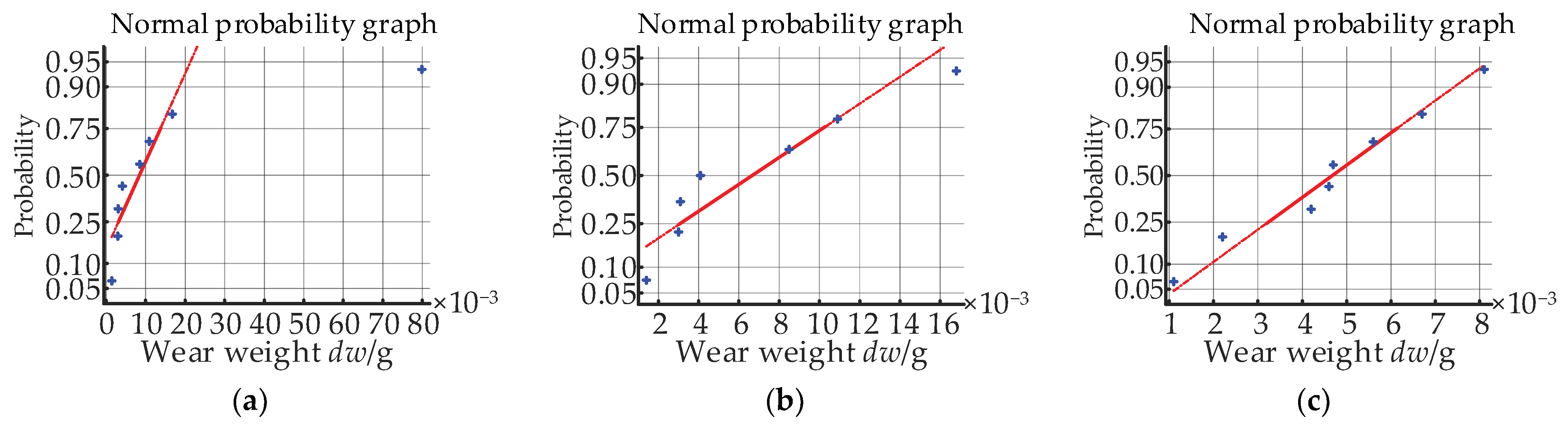
Retaining ring0.01600.02630.1901yes
Retaining ring (without outliers)0.00680.00550.6408yes
Rubber ring0.00470.00230.9434yes
Disclaimer/Publisher’s Note: The statements, opinions and data contained in all publications are solely those of the individual author(s) and contributor(s) and not of MDPI and/or the editor(s). MDPI and/or the editor(s) disclaim responsibility for any injury to people or property resulting from any ideas, methods, instructions or products referred to in the content.

