Predicting Friction of Tapered Roller Bearings with Detailed Multi-Body Simulation Models


Abstract
:1. Introduction
2. Materials and Methods
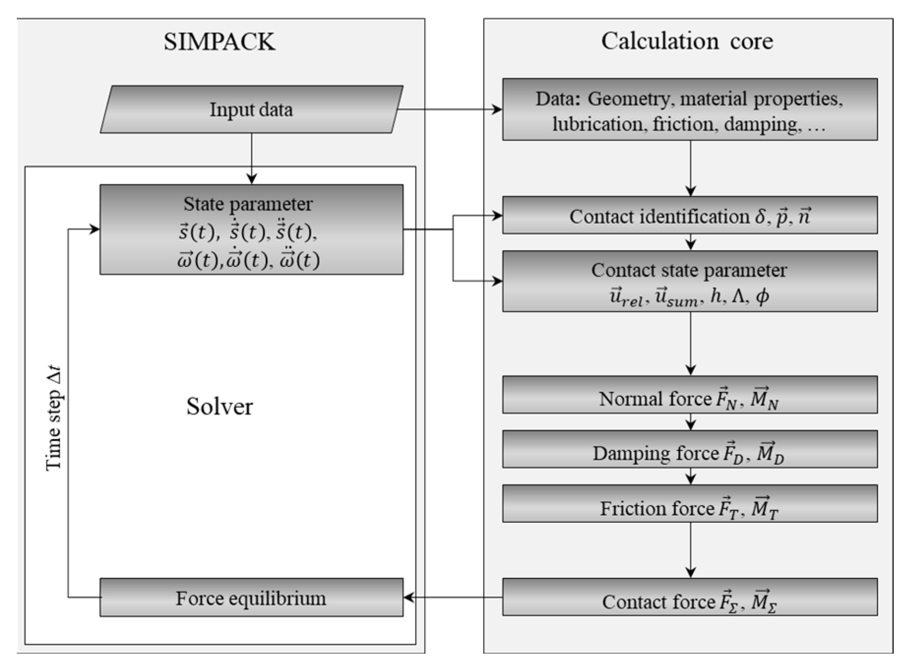
2.1. Multi Body Simulation Model
2.1.1. Contact Calculation
Slice Model
Cell Model
2.1.2. Damping
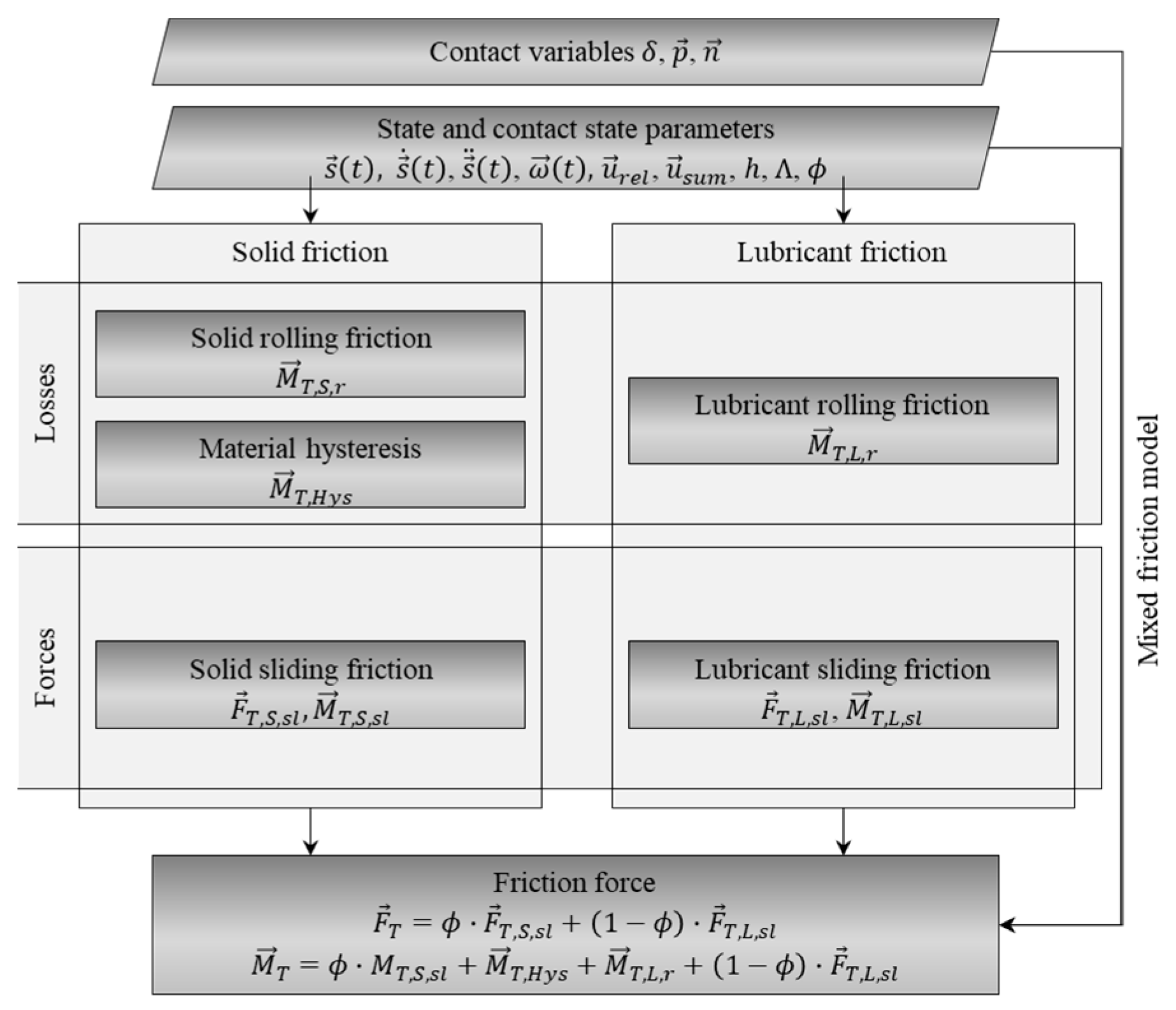
2.1.3. Friction
Lubricant Friction (Sliding)
Lubricant Friction (Rolling)
Solid Rolling Friction
Material Hysteresis
Solid Sliding Friction
Mixed Friction
Friction in Roller Rib Contact
Solid Sliding Friction in Roller Rib Contact
Lubricant Friction in Roller Rib Contact
Mixed Friction
Friction in Roller Cage Contact
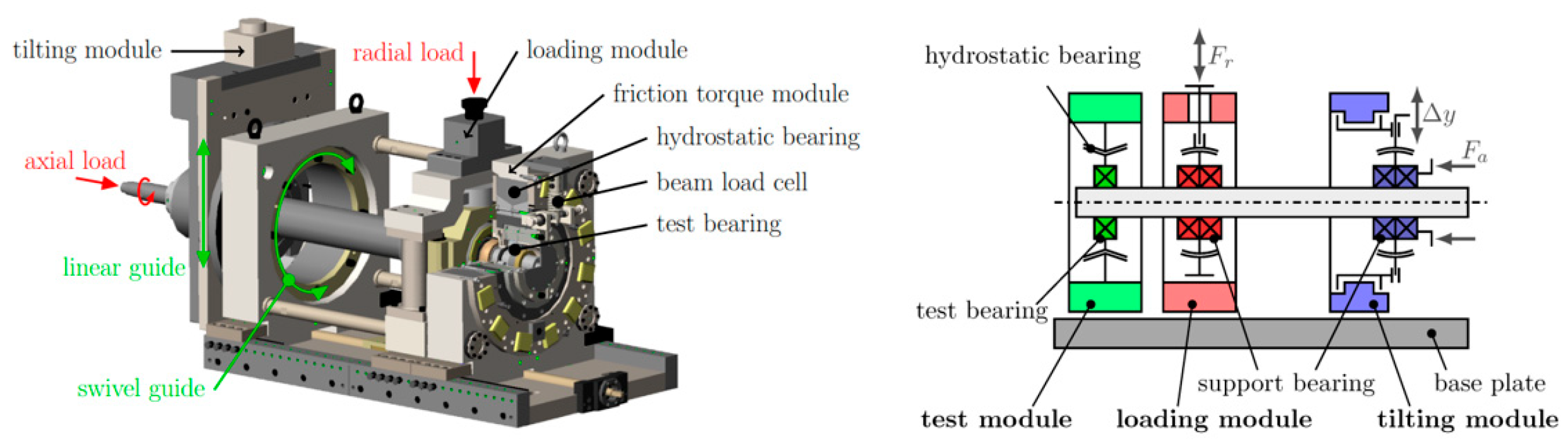
2.2. Friction Torque Measurement
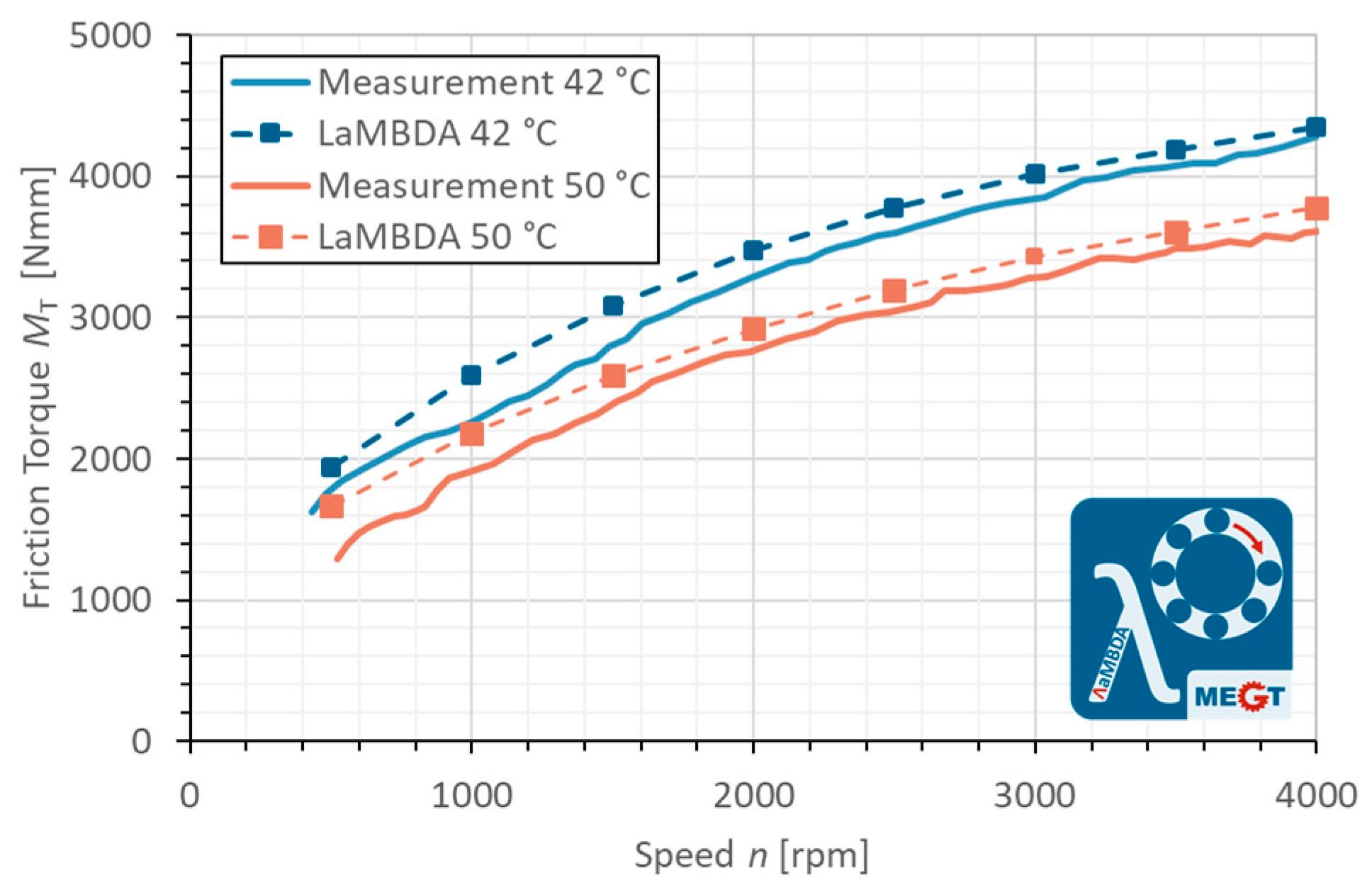
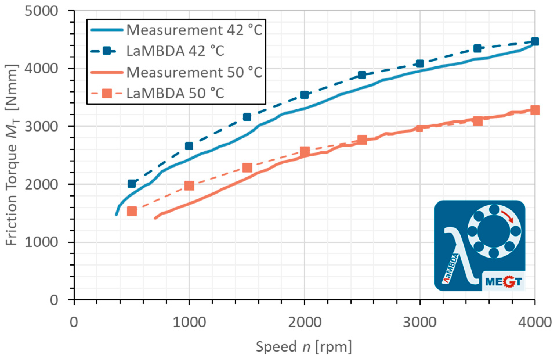
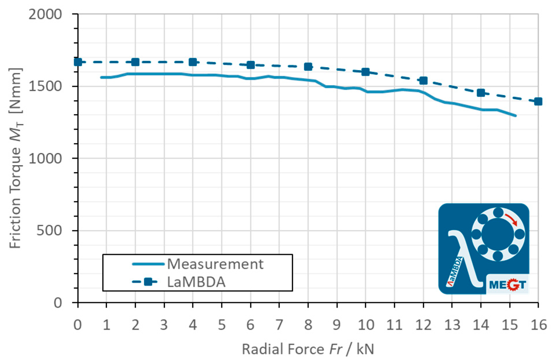
3. Results
4. Discussion
5. Conclusions
Author Contributions
Funding
Data Availability Statement
Acknowledgments
Conflicts of Interest
Nomenclature
| Bearing data | |
| Profile parameter | |
| Profile parameter | |
| Inner diameter | |
| Profile parameter | |
| mean rolling bearing diameter | |
| Inner ring raceway diameter | |
| Outer ring raceway diameter | |
| Pitch diameter | |
| Roller diameter | |
| Profile parameter | |
| Roller length | |
| Number of roller | |
| Edge radius | |
| effective surface of the inner ring | |
| effective surface of the outer ring | |
| Surface roughness parameter according to Zhou and Hoepprich | |
| Basic static load rating, radial | |
| Surface roughness parameter according to Zhou and Hoepprich | |
| Outer diameter | |
| combined standard derivation of surface roughness | |
| Lubricant parameters | |
| Lubricant dependent parameter according to Dicke | |
| Lubricant dependent parameter according to Dicke | |
| Lubricant dependent parameter according to Dicke | |
| Lubricant dependent parameter according to Dicke | |
| thermal corrected lubricant film height | |
| lubricant film height | |
| Lubricant dependent parameter according to Dicke | |
| Lubricant dependent parameter according to Vogel | |
| Lubricant dependent parameter according to Dicke | |
| Lubricant dependent parameter according to Vogel | |
| Lubricant dependent parameter according to Dicke | |
| Lubricant dependent parameter according to Gold et al. | |
| Lubricant dependent parameter according to Gold et al. | |
| Lubricant dependent parameter according to Vogel | |
| Temperature density coefficient | |
| Pressure-viscosity coefficient | |
| Dynamic viscosity of a lubricant | |
| Lubricant viscosity at ambient pressure | |
| thermal conductivity | |
| kinematic viscosity | |
| Lubricant density | |
| Limiting shear stress according to Bair and Winer | |
| thermal correction factors | |
| State variables/states | |
| Axial load | |
| Radial load | |
| cage speed | |
| Inner ring speed | |
| Shaft speed | |
| Displacement between two coordinate systems | |
| Relative velocity between two coordinate systems | |
| Acceleration between two coordinate systems | |
| Absolute temperature | |
| Ambient temperature (20 °C) | |
| Temperature in °C | |
| Angle between two coordinate systems | |
| Angular velocity between two coordinate systems | |
| Angular acceleration between two coordinate systems | |
| Model input parameters | |
| Parameter defining the coefficient of friction | |
| hysteresis loss factor | |
| rolling friction coefficient | |
| rolling resistance exponent | |
| effective contacting length | |
| Limit of relative velocity for static coefficient of friction | |
| Limit of relative velocity for dynamic coefficient of friction | |
| Static coefficient of friction | |
| Dynamic coefficient of friction | |
| Contact state variables | |
| Axis of the contact ellipse | |
| Hertzian contact width/ axis of the contact ellipse | |
| damping coefficient | |
| maximum damping coefficient | |
| Function describing the coefficient of damping depending on penetration depth | |
| lubricant film height | |
| Parameter defining the coefficient of friction | |
| Contact normal vector | |
| Contact pressure | |
| Contact point vector | |
| Relative pressure | |
| Slippage | |
| Average conveying velocity of the lubricant | |
| Relative velocity vector in contact point | |
| Magnitude of relative velocity in contact point | |
| Sum velocity vector in contact point | |
| Magnitude of sum velocity in contact point | |
| Velocity vector in contact normal direction | |
| Effective sliding velocity | |
| Hertzian contact area | |
| Reduced Young’s modulus of both contacting bodies | |
| Magnitude of contact normal force | |
| Contact normal force | |
| Damping force | |
| Force resulting from sliding friction in lubricant | |
| Force resulting from sliding friction in solid contact | |
| Traction force | |
| Contact force | |
| Material parameter | |
| Churning losses inner ring | |
| Churning losses outer ring | |
| Drag losses | |
| Torque from damping force | |
| Torque from contact normal force | |
| Torque from traction force | |
| Torque resulting from material hysteresis | |
| Torque resulting from rolling friction in lubricant | |
| Torque resulting from sliding friction in lubricant | |
| Torque resulting from rolling friction in solid contact | |
| Torque resulting from sliding friction in solid contact | |
| Torque from contact force | |
| load imposed on one slice/cell of the rolling element | |
| proportion of the normal force transmitted at solid contacts | |
| Reduced radii of the contacting bodies | |
| Reduced radius in x direction | |
| Reduced radius in y direction | |
| Velocity parameter | |
| Load parameter | |
| Shear gradient | |
| Penetration depth | |
| Parameter defining the coefficient of friction | |
| Penetration above which maximum damping coefficient is reached | |
| Coefficient of friction | |
| Shear stresses of the lubricant | |
| Solid load-bearing ratio | |
| Thermal load parameter | |
| Duration of a time step | |
| Lubricant film thickness parameter | |
Appendix A

| Parameter | Variable | Value | Unit |
|---|---|---|---|
| Temperature parameter 1 | K | 0.062 | mPa s |
| Temperature parameter 1 | B | 1021.7 | °C |
| Temperature parameter 1 | C | 101.5517 | °C |
| Pressure parameter 1 | a1 | 327.7918 | bar |
| Pressure parameter 1 | a2 | 2.9862 | bar/°C |
| Pressure parameter 1 | b1 | 4.419·10−3 | - |
| Pressure parameter 1 | b2 | 3.0115·10−4 | 1/°C |
| Density at 15 °C | ρ | 887.6 | kg/m³ |
| Thermal conductivity | λ | 0.134 | W/(m K) |
| Temperature density coefficient | α | −6·10−4 | g/(ml K) |
Appendix B
| Parameter | Variable | Value | Unit |
|---|---|---|---|
| Basic static load rating, radial | C0r | 94,000 | N |
| Inner diameter | di | 40 | mm |
| Outer diameter | Da | 80 | mm |
| Pitch diameter | dPd | 60 | mm |
| Roller diameter | dRB | 10 | mm |
| Roller length | lRB | 17 | mm |
| Number of rollers | nRB | 17 | - |
| Profile parameter | ap | 0.0005 | - |
| Profile parameter | cp | 16.2 | mm |
| Profile parameter | dp | 0.0 | mm |
| Profile parameter | kp | 1.0 | mm |
| Edge radius | re | 0.7 | mm |
| Combined standard derivation of roughness | σRaceway | 0.1 | μm |
| σRib | 0.1 | μm | |
| Mixed friction parameters for raceway contact according to Zhou and Hoeprich [61,73] | BZH | 2.1 | |
| CZH | 0.85 | ||
| Mixed friction parameters for rib contact according to Zhou and Hoeprich [61,73] | BZH | 2.1 | |
| CZH | 0.85 |
References
- Woydt, M. The importance of tribology for reducing CO2 emissions and for sustainability. Wear 2021, 474–475, 203768. [Google Scholar] [CrossRef]
- Arora, A.; Jha, S.; Saini, V. Aspects of green-sustainable tribology and its impacts on future product development: A review. Ecol. Environ. Conserv. 2019, 25, S146–S157. [Google Scholar]
- Takahashi, K.; Suzuki, D.; Nagatomo, T. Effect of Axial Clearance on Rolling Element Load of Double Row Tapered Roller Bearings. Q. Rep. RTRI 2019, 60, 196–201. [Google Scholar] [CrossRef]
- Xu, T.; Yang, L.; Wu, Y. Friction torque study on double-row tapered roller bearing. In Proceedings of the 2019 IEEE International Instrumentation and Measurement Technology Conference (I2MTC), Auckland, New Zealand, 20–23 May 2019; pp. 1–6. [Google Scholar] [CrossRef]
- Jiang, Z.; Huang, X.; Zhu, H.; Jiang, R.; Du, S. A new method for contact characteristic analysis of the tapered roller bearing in wind turbine main shaft. Eng. Fail. Anal. 2022, 141, 106729. [Google Scholar] [CrossRef]
- Venner, C.H. Multilevel Solution of the EHL Line and Point Contact Problems. Ph.D. Thesis, Faculty of Mechanical Engineering, Universiteit Twente, Enschede, The Netherland, 1991. [Google Scholar]
- Pan, P.; Hamrock, B.J. Simple Formulas for Performance Parameters Used in Elastohydrodynamically Lubricated Line Contacts. J. Tribol. 1989, 111, 246–251. [Google Scholar] [CrossRef]
- Kragelskii, I.V.; Dobychin, M.N.; Kombalov, V.S. Friction and Wear: Calculation Methods; Pergamon Press: Oxford, UK, 1982; pp. 156–207. [Google Scholar]
- Muraki, M.; Kimura, Y. Traction Characteristics of Lubricating Oils. 2. A Simplified Thermal Theory of Traction with a Non-Linear Viscoelastic Model. J. Jpn. Soc. Lubr. Eng. 1983, 28, 753–760. (In Japanese) [Google Scholar]
- Forster, N.H.; Schrand, J.B.; Gupta, P.K. Viscoelastic Effects in MIL-L-7808-Type Lubricant, Part II: Experimental Data Correlations. Tribol. Trans. 1992, 35, 275–280. [Google Scholar] [CrossRef]
- Gupta, P.K.; Cheng, H.S.; Zhu, D.; Forster, N.H.; Schrand, J.B. Viscoelastic Effects in MIL-L-7808-Type Lubricant, Part I: Analytical Formulation. Tribol. Trans. 1992, 35, 269–274. [Google Scholar] [CrossRef]
- Houpert, L. Piezoviscous-Rigid Rolling and Sliding Traction Forces, Application: The Rolling Element—Cage Pocket Contact. J. Tribol. 1987, 109, 363–370. [Google Scholar] [CrossRef]
- Kannel, J.W.; Bell, J.C. Interpretations of the Thickness of Lubricant Films in Rolling Contact. 1. Examination of Measurements Obtained by X-Rays. J. Lubr. Technol. 1971, 93, 478–484. [Google Scholar] [CrossRef]
- Kannel, J.W.; Walowit, J.A. Simplified Analysis for Tractions between Rolling-Sliding Elastohydrodynamic Contacts. J. Lubr. Technol. 1971, 93, 39–44. [Google Scholar] [CrossRef]
- Goksem, P.G.; Hargreaves, R.A. The Effect of Viscous Shear Heating on Both Film Thickness and Rolling Traction in an EHL Line Contact—Part I: Fully Flooded Conditions. J. Lubr. Technol. 1978, 100, 346–352. [Google Scholar] [CrossRef]
- Dowson, D.; Higginson, G.R. Elasto-Hydrodynamic Lubrication; Pergamon Press: Oxford, UK, 1977; pp. 161–181. [Google Scholar]
- Stribeck, R. Ball Bearing of Various Loads. Trans. ASME 1907, 29, 420–463. [Google Scholar]
- Sjovall, H. The Load Distribution within Ball and roller Bearings under Given External Radial and Axial Loads. Tek. Tidskr. Mek 1933, 9, 97–102. [Google Scholar]
- Lundberg, G.; Palmgren, A. Dynamic Capacity of Roller Bearings. Acta Polytech. Mech. Eng. Ser. R. Swed. Acad. Eng. Sci. 1952, 2, 96–127. [Google Scholar]
- Palmgren, A. Ball and Roller Bearing Engineering; SKF Industries Inc.: Philadelphia, PA, USA, 1959. [Google Scholar]
- Lundberg, G. Elastische Berührung zweier Halbräume. Forsch. Auf Dem Geb. Des Ingenieurwesens 1939, 10, 201–211. [Google Scholar] [CrossRef]
- Palmgren, A.G. Die Lebensdauer von Kugellagern (Life Length of Roller Bearings or Durability of Ball Bearings). Z. Des Vereines Dtsch. Ingenieure 1924, 14, 339–341. [Google Scholar]
- Jones, A.B. A General Theory for Elastically Constrained Ball and Radial Roller Bearings under Arbitrary Load and Speed Conditions. J. Basic Eng. 1960, 82, 309–320. [Google Scholar] [CrossRef]
- Harris, T.A. Rolling Bearing Analysis; Wiley: New York, NY, USA, 1966. [Google Scholar]
- Qian, W. Dynamic Simulation of Cylindrical Roller Bearings—Dynamische Simulation von Zylinderrollenlagern. Ph.D. Thesis, RWTH Aachen, Aachen, Germany, 2014. Available online: https://publications.rwth-aachen.de/record/229010/files/4903.pdf (accessed on 23 August 2023).
- Kiekbusch, T. Strategien zur Dynamischen Simulation von Wälzlagern. Ph.D. Thesis, TU Kaiserslautern, Kaiserslautern, Germany, 2017. Maschinenelemente und Getriebetechnik Berichte BD. 23/2017. [Google Scholar]
- Hong, S.-H.; Tong, V.-C. Rolling-element bearing modeling: A review. Int. J. Precis. Eng. Manuf. 2016, 17, 1729–1749. [Google Scholar] [CrossRef]
- Stacke, L.-E.; Fritzson, D.; Nordling, P. BEAST—A rolling bearing simulation tool. Proc. Inst. Mech. Eng. Part K J. Multi-Body Dyn. 1999, 213, 63–71. [Google Scholar] [CrossRef]
- Stacke, L.-E.; Fritzson, D. Dynamic behavior of rolling bearings: Simulations and experiments. Proc. Inst. Mech. Eng. Part J J. Eng. Tribol. 2001, 215, 499–508. [Google Scholar] [CrossRef]
- Ioannides, E.; Stacke, L.-E.; Fritzson, D.; Nakhimovski, I. Multibody Rolling Bearing Calculations: Computer Programm BEAST. In Proceedings of the World Tribologie Congress III (WTC 2005), Washington, DC, USA, 12–16 September 2005; pp. 903–904. [Google Scholar] [CrossRef]
- Stacke, L.E.; Fritzson, D. Simulation of Rolling Element Bearings. SKF Nova AB S-412 88, SKF, Sweden. 1999. Available online: https://www.researchgate.net/publication/253752292_Simulation_of_Rolling_Element_Bearings (accessed on 28 June 2023).
- Aramaki, H. Rolling Bearing Analysis Program Package BRAIN. Motion Control 1997, 3, 15–24. [Google Scholar]
- Aramaki, H.; Nakano, Y.; Shoda, Y. Rolling Bearing Analysis Codes BRAIN—The Estimation of Rolling Bearing Performance for an Automotive Application. SAE International Congress and Exposition. 1997. Available online: https://www.jstor.org/stable/44731255 (accessed on 23 June 2023).
- Hahn, B.; Smolenski, M.; Neukirchner, J. Investigations of New Cage Designs for the Main Bearings in Multi-Megawatt Wind Power Plants. In Proceedings of the 2nd Conference for Wind Power Drives (CWD), Aachen, Germany, 3–4 March 2015; pp. 321–333. [Google Scholar]
- Houpert, L. CAGEDYN: A Contribution to Roller Bearing Dynamic Calculations Part I: Basic Tribology Concepts. Tribol. Trans. 2009, 53, 1–9. [Google Scholar] [CrossRef]
- Houpert, L. CAGEDYN: A Contribution to Roller Bearing Dynamic Calculations Part II: Description of the Numerical Tool and Its Outputs. Tribol. Trans. 2009, 53, 10–21. [Google Scholar] [CrossRef]
- Houpert, L. CAGEDYN: A Contribution to Roller Bearing Dynamic Calculations. Part III: Experimental Validation. Tribol. Trans. 2010, 53, 848–859. [Google Scholar] [CrossRef]
- Development of the Industry’s Highest Precision and Fastest Integrated Bearing Dynamic Analysis System (IBDAS). Available online: https://www.ntnglobal.com/en/news/new_products/news201100013.html (accessed on 23 August 2023).
- Liu, X.; Deng, S.; Teng, H. Dynamic stability analysis of cages in high-speed oil-lubricated angular contact ball bearings. Trans. Tianjin Univ. 2011, 17, 20–27. [Google Scholar] [CrossRef]
- Jin, K.F.; Yao, T.Q. Multi-Body Contact Dynamics Analysis of Angular Contact Ball Bearing. Appl. Mech. Mater. 2013, 444–445, 45–49. [Google Scholar] [CrossRef]
- Wang, Y.; Wang, W.; Zhang, S.; Zhao, Z. Investigation of skidding in angular contact ball bearings under high speed. Tribol. Int. 2015, 92, 404–417. [Google Scholar] [CrossRef]
- Lacroix, S.; Nélias, D.; Leblanc, A. Four-Point Contact Ball Bearing Model with Deformable Rings. J. Tribol. 2013, 135, 031402. [Google Scholar] [CrossRef]
- Qi, Z.; Wang, G.; Zhang, Z. Contact analysis of deep groove ball bearings in multibody systems. Multibody Syst. Dyn. 2015, 33, 115–141. [Google Scholar] [CrossRef]
- Sopanen, J.; Mikkola, A. Dynamic model of a deep-groove ball bearing including localized and distributed defects. Part 1—Theory. Proc. Inst. Mech. Eng. Part K J. Multi-Body Dyn. 2003, 217, 201–211. [Google Scholar] [CrossRef]
- Sopanen, J.; Mikkola, A. Dynamic model of a deep-groove ball bearing including localized and distributed defects. Part 2—Implementation and results. Proc. Inst. Mech. Eng. Part K J. Multi-Body Dyn. 2003, 217, 213–223. [Google Scholar] [CrossRef]
- Shi, Z.; Liu, J. An improved planar dynamic model for vibration analysis of a cylindrical roller bearing. Mech. Mach. Theory 2020, 153, 103994. [Google Scholar] [CrossRef]
- Liu, J.; Ni, H.; Zhou, R.; Li, X.; Xing, Q.; Pan, G. A Simulation Analysis of Ball Bearing Lubrication Characteristics Considering the Cage Clearance. J. Tribol. 2023, 145, 1128–1146. [Google Scholar] [CrossRef]
- Russell, T.; Sadeghi, F. The effects of lubricant starvation on ball bearing cage pocket friction. Tribol. Int. 2022, 173, 107630. [Google Scholar] [CrossRef]
- Deng, S.; Zhao, G.; Qian, D.; Jiang, S.; Hua, L. Investigation of Oil–Air Flow and Temperature for High-Speed Ball Bearings by Combining Nonlinear Dynamic and Computational Fluid Dynamics Models. J. Tribol. 2022, 144, 071204. [Google Scholar] [CrossRef]
- Weinzapfel, N.; Sadeghi, F. A Discrete Element Approach for Modeling Cage Flexibility in Ball Bearing Dynamics Simulations. J. Tribol. 2009, 131, 021102. [Google Scholar] [CrossRef]
- Nakhaeinejad, M.; Bryant, M.D. Dynamic Modeling of Rolling Element Bearings with Surface Contact Defects using Bond Graphs. J. Tribol. 2011, 133, 011102. [Google Scholar] [CrossRef]
- Ashtekar, A.; Sadeghi, F. A New Approach for Including Cage Flexibility in Dynamic Bearing Models by using Combined Explicit Finite and Discrete Element Methods. J. Tribol. 2012, 134, 041502. [Google Scholar] [CrossRef]
- Brouwer, M.D.; Sadeghi, F.; Ashtekar, A.; Archer, J.; Lancaster, C. Combined Explicit Finite and Discrete Element Methods for Rotor Bearing Dynamic Modeling. Tribol. Trans. 2015, 58, 300–315. [Google Scholar] [CrossRef]
- Ashtekar, A.; Sadeghi, F. Experimental and Analytical Investigation of High Speed Turbocharger Ball Bearings. ASME J. Eng. Gas Turbines Power 2011, 133, 122501. [Google Scholar] [CrossRef]
- Tong, V.-C.; Kwon, S.-W.; Hong, S.-W. Fatigue Life of Cylindrical Roller Bearings. Proc. Inst. Mech. Eng. Part J J. Eng. Tribol. 2016, 231, 623–636. [Google Scholar] [CrossRef]
- Ghaisas, N.; Wassgren, C.R.; Sadeghi, F. Cage Instabilities in Cylindrical Roller Bearings. J. Tribol. 2004, 126, 681–689. [Google Scholar] [CrossRef]
- Singh, S.; Köpke, U.G.; Howard, C.Q.; Petersen, D. Analyses of Contact Forces and Vibration Response for a Defective Rolling Element Bearing using an Explicit Dynamics Finite Element Model. J. Sound Vib. 2014, 333, 5356–5377. [Google Scholar] [CrossRef]
- Aul, E. Analyse von Relativbewegungen in Wälzlagersitzen. Ph.D. Thesis, TU Kaiserslautern, Kaiserslautern, Germany, 2008. Maschinenelemente und Getriebetechnik Berichte BD. 05/2008. [Google Scholar]
- Mármol Fernández, M. Development of a New Bearing Geometry to Reduce Friction Losses. Ph.D. Thesis, TU Kaiserslautern, Kaiserslautern, Germany, 2022. Maschinenelemente und Getriebetechnik Berichte BD. 43/2022. [Google Scholar]
- Kiekbusch, T.; Sauer, B. Calculation of the dynamic behavior of rolling bearings with detailed contact calculations. In Proceedings of the EUROMECH Colloquium 578, Rolling Contact Mechanics for Multibody System Dynamics, Funchal, Portugal, 10–13 April 2017; ISBN 978-989-99424-3-1. [Google Scholar]
- Teutsch, R. Kontaktmodelle und Strategien zur Simulation von Wälzlagern und Wälzführungen. Ph.D. Thesis, TU Kaiserslautern, Kaiserslautern, Germany, 2005. Maschinenelemente und Getriebetechnik Berichte BD. 01/2005. [Google Scholar]
- DIN ISO 26281; Wälzlager—Dynamische Tragzahlen und Nominelle Lebensdauer-Berechnung der Modifizierten Nominellen Referenz-Lebensdauer für Wälzlager. European Committee for Standardization: Brussels, Belgium, 2010.
- Teutsch, R.; Sauer, B. An Alternative Slicing Technique to Consider Pressure Concentrations in Non-Hertzian Line Contacts. ASME J. Tribol. 2004, 126, 436–442. [Google Scholar] [CrossRef]
- Polonsky, I.A.; Keer, L.M. A numerical method for solving rough contact problems based on the multi-level multi-summation and conjugate gradient techniques. Wear 1999, 231, 206–219. [Google Scholar] [CrossRef]
- Boussinesq, J. Application des Potentiels à l’étude de l’équilibre et du Mouvement des Solides élastiques: Principalement au Calcul des Déformations et des Pressions que Produisent, dans ces Solides, des Efforts Quelconques Exercés sur une Petite Partie de leur Surface ou de leur Intérieur: Mémoire Suivi de Notes Etendues sur Divers Points de Physique, Mathématique et d’analyse; Gauthier-Villars: Paris, France, 1885. [Google Scholar]
- Dietl, P. Damping and Stiffness Characteristics of Rolling Element Bearings: Theory and Experiment. Ph.D. Thesis, Technische Universität Wien, Vienna, Austria, 1997. [Google Scholar] [CrossRef]
- Wisniewsky, M. Elastohydrodynamische Schmierung. In Handbuch der Tribologie und Schmierungstechnik, 9th ed.; Expert-Verlag: Renningen, Germany, 2000. [Google Scholar]
- Bair, S.; Winer, W.O. A Rheological Model for Elastohydrodynamic Contacts Based on Primary Laboratory Data. ASME J. Lubr. Technol. 1979, 101, 258–265. [Google Scholar] [CrossRef]
- Peeken, H.; Dicke, H.; Welsch, G. Viscosity-Pressure-Temperature Characteristics of Different Types of Lubricants and their Possible Influence on Fatigue. In Proceedings of the 3rd World Congress on Gearing and Power Transmission, Paris, France, 12–14.February 1992; pp. 527–536. [Google Scholar]
- Gold, P.W.; Schmidt, A.; Loos, J.; Aßmann, C. Viskositäts-Druck-Koeffizienten von mineralischen und synthetischen Schmierölen. Tribol. Schmier. 2001, 48, 40–48. [Google Scholar]
- Lubenow, K. Axialtragfähigkeit und Bordreibung von Zylinderrollenlagern. Ph.D. Thesis, Universität Bochum, Bochum, Germany, 2002. [Google Scholar]
- Aramaki, H.; Cheng, H.S.; Zhu, D. Film Thickness, Friction, and Scuffing Failure of Rib/Roller End Contacts in Cylindrical Roller Bearings. J. Tribol. 1992, 114, 311–316. [Google Scholar] [CrossRef]
- Zhou, R.S.; Hoeprich, M.R. Torque of Tapered Roller Bearings. ASME J. Tribol. 1991, 113, 590–597. [Google Scholar] [CrossRef]
- Engel, S. Reibungs-und Ermüdungsverhalten des Rad-Schiene-Systems mit und ohne Schmierung. Ph.D. Thesis, Universität Magdeburg, Magdeburg, Germany, 2002. [Google Scholar]
- Biboulet, N.; Houpert, L. Hydrodynamic force and moment in pure rolling lubricated contacts. Part 1—Line contacts. Proc. Inst. Mech. Eng. Part J J. Eng. Tribol. 2010, 224, 765–775. [Google Scholar] [CrossRef]
- Scheuermann, M. Dynamiksimulation zur Virtuellen Produktentwicklung von Rollenschienenführungen. Ph.D. Thesis, TU Kaiserslautern, Kaiserslautern, Germany, 2010. Maschinenelemente und Getriebetechnik Berichte BD. 07/2021. [Google Scholar]
- Stolarski, T.A.; Tobe, S. Rolling Contacts; Professional Engineering Publishing Limited: London, UK, 2000; pp. 55–73. [Google Scholar]
- Johnson, K. Contact Mechanics; Cambridge University Press: Cambridge, UK, 1985. [Google Scholar]
- Wang, Q.; Chung, Y.-W. Encyclopedia of Tribology; Springer: New York, NY, USA, 2013. [Google Scholar]
- Steinert, T. Das Reibmoment von Kugellagern mit Bordgeführtem Käfig. Ph.D. Thesis, RWTH Aachen, Shaker Verlag, Aachen, Germany, 1996. [Google Scholar]
- Sebteini, S.; Hudak, R. Mindestlast von Wälzlagern. Abschlussbericht zum Forschungsvorhaben Nr. 830 I (Heft 1504); FVA Forschungsvereinigung Antriebstechnik e.V.: Frankfurt am Main, Germany, 2022. [Google Scholar]
- Liebrecht, J. Technisch-Mathematischer Ansatz zur Berechnung der Hydraulischen Verluste in Wälzlagern. Ph.D. Thesis, RPTU Rheinland-Pfälzische Technische Universität Kaiserslautern Landau, Kaiserslautern, Germany, 2018. Maschinenelemente und Getriebetechnik Berichte Bd. 30/2018. [Google Scholar]
- Gonda, A.; Sauer, B.; Großberndt, D.; Schwarze, H. Experimentelle und numerische Untersuchungen der hydraulischen Verluste in voll-und teilgefluteten kegelrollenlagern. VDI Berichte 2019, 2348, 97–106. [Google Scholar] [CrossRef]
- Maccioni, L.; Ruth, L.; Koch, O.; Concli, F. Load-independent power losses of full-flooded lubricated tapered roller bearings: Numerical and experimental investigation of the effect of operating temperature and housing walls distances. Tribol. Trans. 2023, in press.
- Maccioni, L.; Chernoray, V.G.; Mastrone, M.N.; Bohnert, C.; Concli, F. Study of the impact of aeration on the lubricant behavior in a tapered roller bearing: Innovative numerical modelling and validation via particle image velocimetry. Tribol. Int. 2022, 165, 107301. [Google Scholar] [CrossRef]
- Maccioni, L.; Chernoray, V.G.; Bohnert, C.; Concli, F. Particle Image Velocimetry measurements inside a tapered roller bearing with an outer ring made of sapphire: Design and operation of an innovative test rig. Tribol. Int. 2022, 165, 107313. [Google Scholar] [CrossRef]
- Maccioni, L.; Chernoray, V.G.; Concli, F. Fluxes in a full-flooded lubricated Tapered Roller Bearing: Particle Image Velocimetry measurements and Computational Fluid Dynamics simulations. Tribol. Int. 2023, 188, 108824. [Google Scholar] [CrossRef]
- Maccioni, L.; Concli, F. Computational fluid dynamics applied to lubricated mechanical components: Review of the approaches to simulate gears, bearings, and pumps. Appl. Sci. 2020, 10, 8810. [Google Scholar] [CrossRef]
- Brouwer, L.; Bader, N.; Beilicke, R.; Schwarze, H.; Poll, G.; Deters, L. Tribologische Fluidmodelle Nebenaggregate—Tribologische Fluidmodelle für Nebenantriebsaggregate in Hybrid- und Elektrofahrzeugen—Abschlussbericht zum FVV-Forschungsvorhaben 597 (Heft 1092); Forschungsvereinigung Verbrennungskraftmaschinen e. V.: Frankfurt am Main, Germany, 2016. [Google Scholar]


| Parameter | Variable | Value | Unit |
|---|---|---|---|
| Axial load | Fa | 6 | kN |
| Radial load | Fr | 0 | kN |
| Temperature | 42 and 50 | °C | |
| Shaft speed | N | 500–4000 | rpm |
| Lubrication | Oil bath half roller height | ||
| Lubricant | Reference oil FVA3 |
| Parameter | Variable | Value | Unit |
|---|---|---|---|
| Axial load | Fa | 6 | kN |
| Radial load | Fr | 6.5 | kN |
| Temperature | 42 and 50 | °C | |
| Shaft speed | N | 500–4000 | rpm |
| Lubrication | Oil bath half roller height | ||
| Lubricant | Reference oil FVA3 |
| Parameter | Variable | Value | Unit |
|---|---|---|---|
| Axial load | Fa | 6.5 | kN |
| Radial load | Fr | 1–15 | kN |
| Temperature | 50 | °C | |
| Shaft speed | N | 2000 | rpm |
| Lubrication | Oil bath half roller height | ||
| Lubricant | Reference oil FVA3 |
| Parameter | Variable | Value | Unit |
|---|---|---|---|
| Basic static load rating, radial | C0r | 260,000 | N |
| Inner diameter | di | 80 | mm |
| Outer diameter | Da | 140 | mm |
| Pitch diameter | dPd | 108.5 | mm |
| Roller diameter | dRB | 17 | mm |
| Roller length | lRB | 22.7 | mm |
| Number of roller | nRB | 16 | - |
| Profile parameter | ap | 0.0005 | - |
| Profile parameter | cp | 20.7 | mm |
| Profile parameter | dp | 0.0 | mm |
| Profile parameter | kp | 2.0 | mm |
| Edge radius | re | 1.0 | mm |
| Combined standard derivation of roughness | σRaceway | 0.16 | μm |
| σRib | 0.24 | μm | |
| Mixed friction parameters for raceway contact according to Zhou and Hoeprich [61,73] | BZH | 2.32 | |
| CZH | 0.97 | ||
| Mixed friction parameters for rib contact according to Zhou and Hoeprich [61,73] | BZH | 1.90 | |
| CZH | 0.99 |
Disclaimer/Publisher’s Note: The statements, opinions and data contained in all publications are solely those of the individual author(s) and contributor(s) and not of MDPI and/or the editor(s). MDPI and/or the editor(s) disclaim responsibility for any injury to people or property resulting from any ideas, methods, instructions or products referred to in the content. |
© 2023 by the authors. Licensee MDPI, Basel, Switzerland. This article is an open access article distributed under the terms and conditions of the Creative Commons Attribution (CC BY) license (https://creativecommons.org/licenses/by/4.0/).
Share and Cite
Wingertszahn, P.; Koch, O.; Maccioni, L.; Concli, F.; Sauer, B. Predicting Friction of Tapered Roller Bearings with Detailed Multi-Body Simulation Models. Lubricants 2023, 11, 369. https://doi.org/10.3390/lubricants11090369
Wingertszahn P, Koch O, Maccioni L, Concli F, Sauer B. Predicting Friction of Tapered Roller Bearings with Detailed Multi-Body Simulation Models. Lubricants. 2023; 11(9):369. https://doi.org/10.3390/lubricants11090369
Chicago/Turabian StyleWingertszahn, Patrick, Oliver Koch, Lorenzo Maccioni, Franco Concli, and Bernd Sauer. 2023. "Predicting Friction of Tapered Roller Bearings with Detailed Multi-Body Simulation Models" Lubricants 11, no. 9: 369. https://doi.org/10.3390/lubricants11090369