Article

Dynamic Responses of the Planetary Gear Mechanism Considering Dynamic Wear Effects

1
Department of Mechanical Engineering, Harbin Institute of Technology, Weihai 264209, China
2
Department of Astronautics Engineering, Harbin Institute of Technology, Harbin 150001, China
*
Author to whom correspondence should be addressed.
Lubricants 2023, 11(6), 255; https://doi.org/10.3390/lubricants11060255
Submission received: 15 May 2023 / Revised: 2 June 2023 / Accepted: 6 June 2023 / Published: 9 June 2023

Abstract

:
Gear wear is unavoidable and results in vibrations and decreased performance in a planetary gear system. In this work, the wear phenomenon of the gear teeth surface and the dynamic responses of the planetary gear mechanism are investigated through a computational methodology. Dynamic responses are presented by considering the dynamic wear effects. First, the model of the planetary gear mechanism dynamics is established by considering the nonlinear stiffness and friction of gear surfaces. The dynamic wear model of the gear is then established based on Archard’s wear model. Further, the coupling between the dynamics and wear characteristics of the planetary gear mechanism is presented by considering the dynamic wear effects. Finally, a numerical investigation is conducted. The simulation results reveal severe wear between the sun and planet gears. The wear depth and meshing vibration responses exhibit prominent nonlinear characteristics. The low-order resonance of the meshing frequency becomes more marked as the mesh times and wear increase.

1. Introduction

Planetary gear transmission, one of the most popular types of mechanical transmission, is usually used in various kinds of mechanisms. It benefits from its small size, high transmission ratio, and high load capacity. It is inevitable that wear exists in the gear transmission system. Consequently, the vibration of the planetary transmission system will be aggravated, and the transmission accuracy will decrease as a result of the coupling between gear wear and the dynamics of planetary transmission. In order to predict the performances of the planetary transmission gears, it is crucial to thoroughly investigate the wear characteristics of planetary transmission gears as well as the dynamic performances of planetary transmission.
Many studies have been conducted on the dynamic characteristics of the gear transmission system. Kahraman et al. [1,2,3,4] established the dynamic model of planetary gear clearance, considered the factors of gear-meshing error, tooth side clearance, mesh stiffness, and bearing clearance, and summarized the influence of different types of clearances on gear dynamic characteristics, which laid a foundation for the study of planetary gear clearance dynamics. Parker [5,6] analyzed the relationship between planet phasing and the planetary gear vibration, and the method simulating the vibration of the planetary gear. Ambarisha et al. [7] analyzed the nonlinear dynamic characteristics of the planetary gear. Huang [8] proposed a mathematical model to simulate the vibration of the planetary gear. Considering the influence of gear backlash, Wang [9,10] established a gear dynamics model considering torsional vibration to study the gear-meshing dynamics. It was proposed that the introduction of tooth side clearance would enhance the nonlinear characteristics of the gear, which was verified by experiments. Nevzat and Houser [11] summarized the gear-meshing dynamics model, which laid a theoretical foundation for analyzing the influence of tooth backlash on gear nonlinear dynamics. In the work of Shi et al. [12], the separation of tooth surface caused by the nonlinear change of tooth clearance was analyzed. A variety of meshing conditions such as tooth back meshing were established under the conditions of tooth surface separation, active tooth meshing, and tooth back meshing. Al-Shyyab [13] established the nonlinear model for planetary gears and studied the key parameters of the nonlinear dynamic responses of these gears. Lin and Parker [14,15] considered the gyro effect of gears. By analyzing the sensitivity of different parameters through modal energy distribution, the sensitivity of natural frequency to working speed is obtained, and the influence of the gyro effect is analyzed. Xiang [16] proposed a nonlinear planetary gear dynamic model that considers the comprehensive gear error and time-varying mesh stiffness. The results showed nonlinear characteristics at different frequencies. Ligata [17,18] conducted an experimental study to analyze the effect of manufacturing errors on planetary gear stresses and planet load-sharing. He et al. [19] comprehensively considered the influence of tooth surface friction and lubrication, established the gear-friction dynamic equation, and predicted the gear tooth surface-friction force. Dong and Yuan [20,21] calculated the meshing characteristics of cylindrical gears under elastohydrodynamic lubrication and analyzed the effects of different operating parameters on friction and mesh force. Zhang et al. [22] proposed a method to predict the friction coefficient and wear of spiral bevel gears that considers the effect of the mixed lubrication condition. Chen [23,24] combined tooth backlash and tooth surface friction and analyzed the nonlinear rotation dynamic characteristics of gears. Additionally, Guo [25,26,27], Kim [28], Ma [29], Sánchez [30,31], Chen [32], Sun [33], and Tsai [34] have presented a large number of research studies on planetary gear dynamics.
The wear of gear exists during the working of a transmission system and the dynamic responses of gear changes with gear-wear development. Flodin and Sndersson [35,36,37,38] proposed a wear discretization model and applied it to the calculation of gear wear. Shen et al. [39,40] proposed a pure torsion dynamic model of planetary gear that takes into consideration gear wear. Archard’s model is used to calculate gear wear, and time-varying mesh stiffness, no-load static transmission error, and tooth backlash are introduced into the dynamic model. Guerin et al. [41] considered that the tooth surface-friction coefficient cannot be accurately estimated when the gear is running, so the polynomial chaotic projection method was used to study the dynamic response of the spur gear system, taking into consideration the uncertain tooth surface-friction coefficient. Straffelini et al. [42] hypothesized that gear wear could change the gear tooth clearance and thus change the gear dynamic characteristics, and the calculated results of wear distribution using the Archard wear model were in good agreement with the actual observed results. Li et al. [43,44] proposed a dynamic model to simulate the contact fatigue and surface wear of spur gear, in which the effect of input torque, roughness of gear teeth, and lubricant are involved. Yan et al. [45,46] presented a model of a spur gear considering the coupling of the effect between surface wear and fatigue, and the effects of gear teeth surface wear on the service life were analyzed. Bajpai [47] proposed a surface-wear prediction methodology based on finite elements for spur and helical gears. Yuksel [48] analyzed the influence of gear wear on the planetary gear dynamic tooth loads. The gear wear has a significant influence on off-resonance speed ranges. Ding [49] established two dynamic models of planetary gears to find the interactions between nonlinear spur gear dynamics and surface wear. The results indicated that gear wear reduced the nonlinear forced response at the initial stage. However, the nonlinear forced response would appear again as the wear increased continuously. Wu [50] and Zhou [51] also performed investigations to develop the gear-wear theory. Additionally, Choy [52], Wojnarowski [53], Zhang [54], and Feng [55] focused on gear wear and analyzed the gear performance. It is important to note that wear will increase the backlash size of gearing and, as a result, affect the dynamic performance of transmission mechanisms. Wear leads to a decrease in the precision of mechanisms, particularly for high accuracy and long lifespan mechanisms.
Therefore, it is necessary to thoroughly investigate and discuss the effects of wear on dynamic responses of gear transmission in mechanical systems. To understand the effects of gear wear on the dynamic responses of planetary gears during long-term operations, this paper presents a computational methodology to investigate the vibration responses of planetary gear mechanisms by considering dynamic wear effects. First, a time-varying dynamic model of planetary gears is proposed. The parameters of the dynamic model vary with the number of mesh cycles, and the mesh forces and tangential friction forces are obtained to describe the contact–impact forces on the gear surface. Second, a dynamic wear model of the gear is developed to predict the dynamic wear depth on the gear surface. Finally, the proposed model is used to study the wear and dynamic responses of a planetary gear transmission system. The computational process involves the following steps: (1) obtaining the mesh forces on the gear surface, (2) analyzing the distribution of gear wear using the gear wear model, and (3) updating the backlash and gear surface to obtain the dynamic characteristics of the gear transmission system.
This paper is organized as follows: Section 2 presents the rotational dynamic model of planetary gears, considering the friction of gear teeth. The model of the time-varying stiffness of the gear mesh is introduced in Section 3. Section 4 proposes the wear model of gear teeth. The simulation process coupling the wear model and gear dynamics are presented in Section 5. Section 6 presents the simulation results of mesh stiffness, gear-wear depth, and meshing vibration at different rotational speeds. Section 7 summarizes the conclusion of the presented work.

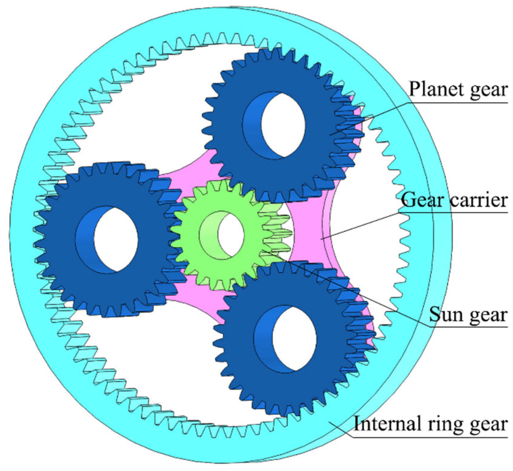
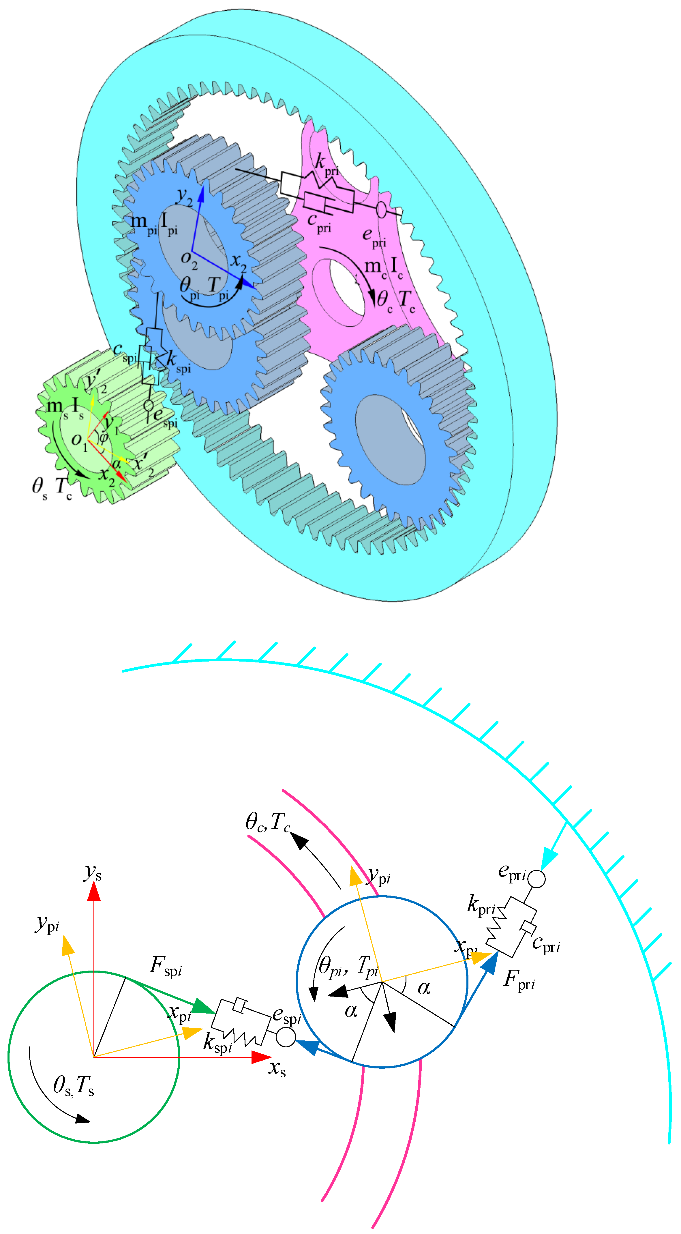
2. Rotational Dynamic Model of Planetary Gear Mechanism

In this section, a dynamic model of the planetary gear mechanism is established to analyze the vibration responses of the planetary gear transmission system. As shown in Figure 1, the planetary gear mechanism comprises the sun gear, planet gears, ring gear, and planet-gear carrier. An angle of 120° was utilized in the configuration of the three planet gears.
To simplify the dynamic model of the planetary gear mechanism, certain assumptions are made:
(1) The planetary gear mechanism is planar, with one degree of freedom.
(2) Each component is assumed to be rigid.
(3) The tooth profile is involute, and each planet gear in the planetary gear system has the same uniform parameters.
(4) The initial backlashes and comprehensive transmission errors are zero.
To describe the motion of the gears, their coordinate systems must first be established. Figure 2 shows the coordinate systems and parameters of the planetary gear system.
In Figure 2, θ, s, pi, and c represent the rotational displacement, sun gear, ith-planet gear, and planet-gear carrier, respectively. T s , T s p i , and T c denote the torques of the sun gear, ith-planet gear, and planet-gear carrier, respectively. I s and I p i are the inertia moment of the sun gear and ith-planet gear, respectively. I c is the inertia moment of the planet gear and its carrier. The masses of the sun gear, ith-planet gear, and planet-gear carrier are m s , m p i , and m c , respectively. k s p i and k p r i represent the varying mesh stiffness of the tooth pair of the ith-planet–sun meshing pair and the tooth pair of the planet–ring meshing pair, respectively. c s p i is the varying meshing dampness of the ith-planet–sun meshing pair. c p r i is the varying meshing dampness of ith-planet–ring meshing pair. e s p i is the tooth-profile meshing error of ith-planet–sun meshing pair. e p r i is the tooth-profile meshing error of ith-planet–ring meshing pair. α is the gear pressure angle. φ is the rotation angle of the coordinate system x 2 O y 2 . x 1 O y 1 is the global coordinate system, and x 1 O y 1 is the rotating coordinate system. x 2 O y 2 is the body coordinate system of the planet gear.
When the gear teeth contact, the surfaces of the gear teeth are affected by frictional forces. The loads and directions of the frictional forces are related to the meshing configuration. A single-tooth meshing area and two double-tooth meshing areas are present when the gears mesh. Figure 3 presents the contact forces between gear teeth during single-tooth and double-tooth meshing.
In Figure 3, Rs is the basic radius of the sun gear, and Rpi is the basic radius of the ith-planet gear. Rc is the rotation radius of the planet gear axis. sp and ps denote the forces acting on the sun and planet gears, respectively. rp and pr denote the forces of the internal ring gear and planet gear, respectively. fmij (m = sp, ps, rp, pr; j =1,2) is the friction force between the ith-planet gear and jth-tooth meshing pair. Fmij (m = sp, ps, rp, pr; j = 1, 2) represents the normal forces between the ith-planet gear and jth-tooth meshing pair.
Further, the dynamic equations of the planetary gear mechanism are obtained by analyzing the forces on the gears, which are expressed as follows:
{ I s θ ¨ s = T s R s i = 1 N j = 1 n z F s p i j i = 1 N j = 1 n z Λ s p i j ρ s p i j μ s p i j F s p i j I p i θ ¨ p i = R p i j = 1 n z F p s i j + j = 1 n z Λ p s i j ρ p s i j μ p s i j F p s i j R p i j = 1 n z F p r i j j = 1 n z Λ p r i j ρ p r i j μ p r i j F p r i j ( I c + i = 1 N I p i ) θ ¨ c = R s i = 1 N j = 1 n z F s p i j + i = 1 N j = 1 n z Λ s p i j ρ s p i j μ s p i j F s p i j + R r i = 1 N j = 1 n z F r p i j + i = 1 N j = 1 n z Λ r p i j ρ r p i j μ r p i j F r p i j + T c
where the directions of the surface frictional forces are represented by Λspij, Λpsij, Λprij, and Λrpij (i = 1, 2, 3; j = 1, 2), and these values can be −1 or 1; ρspij, ρpsij, ρprij, and ρrpij (i = 1, 2, 3; j = 1, 2) are the radius of curvature at the contact point; and μspij, μpsij, μprij, and μrpij (i = 1, 2, 3; j = 1, 2) are the coefficients of dynamic friction. N is the number of the planet gears. nz is the number of meshing teeth pairs.
The normal meshing force of gearing involves two terms, that is, elastic forces and damping forces. The normal elastic force can be calculated using the penetration depth of the gear teeth surfaces, as shown below:
F m i = { k m i ( δ m i b ) 0 k m i ( δ m i + b ) , , , δ m i > b b < δ m i < b δ m i < b
where b is the backlash, δ m i is the related distance along the mesh line of meshing gears, and m = sp, pr; i = 1, 2, 3.
Considering the tooth-profile meshing error in the sun–planet gear and planet–internal gear pairs, δ m i is given by:
δ s p i = { δ s p i e s p i 0 δ s p i + e s p i , δ s p i e s p i , e s p i δ s p i e s p i , δ s p i e s p i
δ p r i = { δ p r i e p r i 0 δ p r i + e p r i , δ p r i e p r i , e p r i δ p r i e p r i , δ p r i e p r i
where e p r i and e p r i are the tooth-profile meshing errors. δ s p i and δ p r i represent the linear displacement along the mesh line and they are given by:
{ δ s p i = r s θ s r p i θ p i r c θ c cos α δ r p i = r p i θ p i r c θ c cos α
After substituting Equations (2)–(5) into Equation (1), and considering the damping force, we can obtain the following equation:
{ δ ¨ s p i F s p i M s p i + F r p i R s M c p R c + ( 1 M s + R s M c p R c ) ( i = 1 N F s p i + i = 1 N F c s p i + i = 1 N j = 1 n z Λ s p i j S s p i j f s p i j ) + R r M c p R c ( i = 1 N F r p i + i = 1 N F c r p i + i = 1 N j = 1 n z Λ r p i j S r p i j f r p i j ) = T s M s R s T c M c p R c δ ¨ r p i + F s p i M s p i F r p i M s p i + R s M c p R c ( i = 1 N F s p i + i = 1 N F c s p i + i = 1 N j = 1 n z Λ s p i j S s p i j f s p i j ) + R r M c p R c ( i = 1 N F r p i + i = 1 N F c r p i + i = 1 N j = 1 n z Λ r p i j S r p i j f r p i j ) = T c M c p R c
where Fcspi and Fcrpi are the damping forces between the planet and sun gears, respectively; Mspi is the mass of the ith-planet gear; and Sspij, Spsij, Sprij, and Srpij are the equivalent curvature radii of the tooth surface, where S s p i j = ρ s p i j / R s , S p s i j = ρ s p i j / R p i , S p r i j = ρ p r i j / R p i , and S r p i j = ρ r p i j / R r . Ms is the mass of the sun gear, and Mcp is the equivalent mass of the planet carrier with all planet gears, which is expressed as M c p = ( I c + i N I p i ) / R c .
Damping forces can be obtained from Equation (7).
F c m i = c m i δ ˙ m i
where c m i is the meshing damping, m = sp, pr; i = 1, 2, 3.
Tangential friction forces can be obtained from Equation (8).
f m i = μ m i F m i
where μ m i is the dynamic friction coefficient.

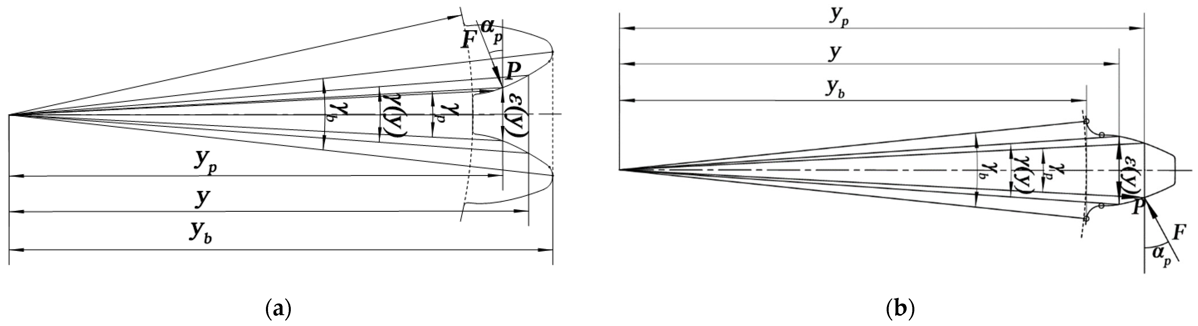
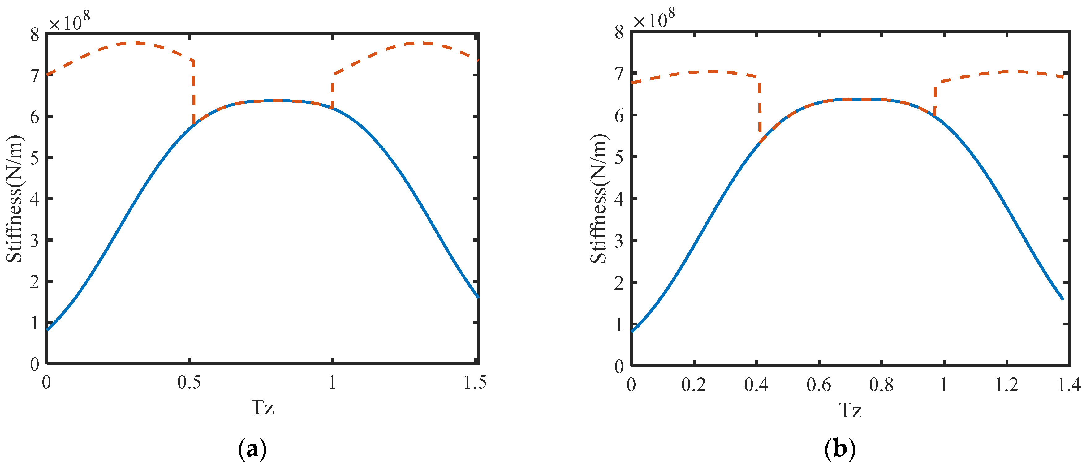
3. Modeling Gear Mesh Stiffness

The model of nonlinear mesh stiffness for planetary gears was derived by applying the principle of minimum potential energy (PMPE). This model accommodates both sun–planet and planet–ring mesh configurations. The mesh stiffness on mesh points is also examined in this section. Stiffness excitation is a major contributor to the dynamic mesh force and vibration responses in gears, which can lead to shock and decrease the stability of the gear transmission. To analyze the dynamic mesh force, the time-varying feature of mesh stiffness should be considered. In this study, the gear teeth were modeled as variable-section cantilever beams on the base circle. The mesh stiffness can also be simplified as the contact of several beams. Therefore, the mesh stiffness can be expressed as Equation (9) [31]
K s = K 1 K 2 K H K 1 + K 2 + K H = K s ( ξ )
where K1 and K2 are the driving and driven stiffness, respectively; KH is the contact stiffness; and ξ is the contact coefficient at point P. The mesh stiffness can be determined from Equation (10) according to PMPE.
K i = ( 1 k i x + 1 k i s + 1 k i n ) 1
where kx is the bending stiffness, ks is the shear stiffness, and kn is the axial compressive stiffness.
1 k x = ± 12 E B y b y p [ ± ( y p y ) cos α p r p sin γ p 2 sin α p ] 2 d y ε 3 ( y ) 1 k n = ± 1 E B y b y p sin 2 α p d y ε ( y ) 1 k s = ± C s 1 G B y b y p cos 2 α p d y ε ( y )
where αp is the pressure angle at point P, γp is the angular thickness at point P, E is the elasticity modulus, G is the shear modulus, B is the gear width, and y is the axial distance of point P. ε(y) is the chordal thickness at point P; yb and yp are the distances to the gear-tooth root and point P, respectively; Cs is the equivalent correction factor; and Cs = 1.5. The gear parameters are shown in Figure 4.
ε(y) is obtained from Equation (12).
ε ( y ) = 2 tan ( π + 4 x tan α 2 z ( i n v α P i n v α ) ) y
where x is the gear modification coefficient, z is the tooth number, and α = 0.349066 rad, that is, 20°.

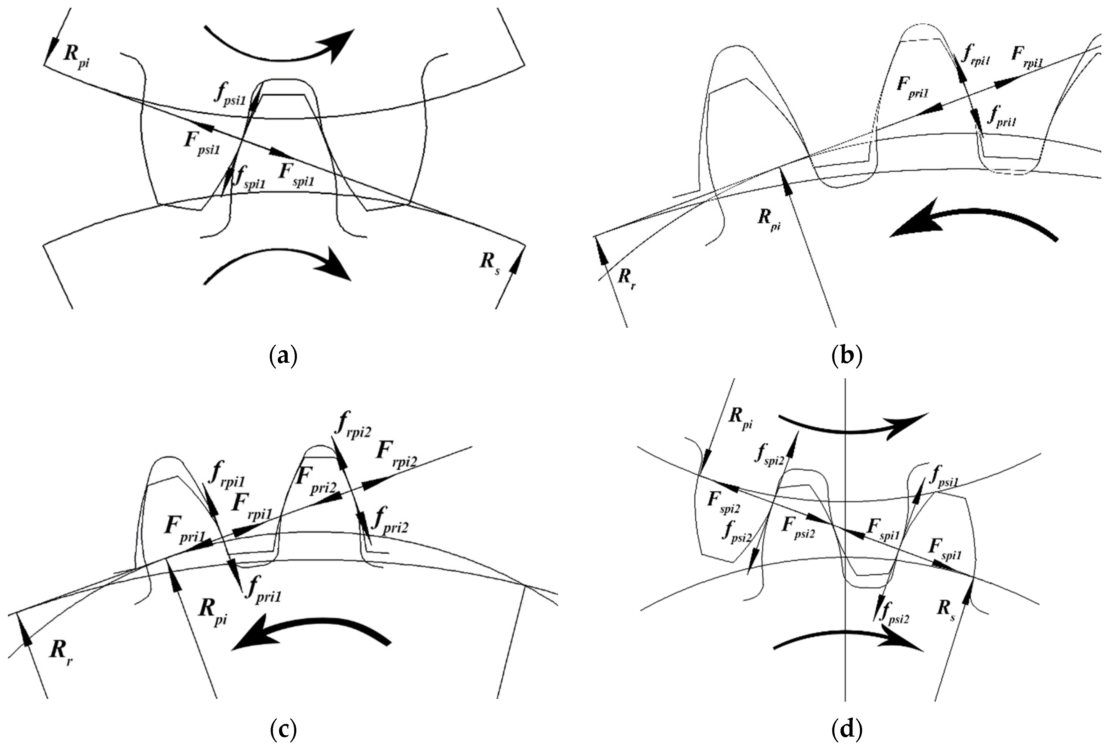
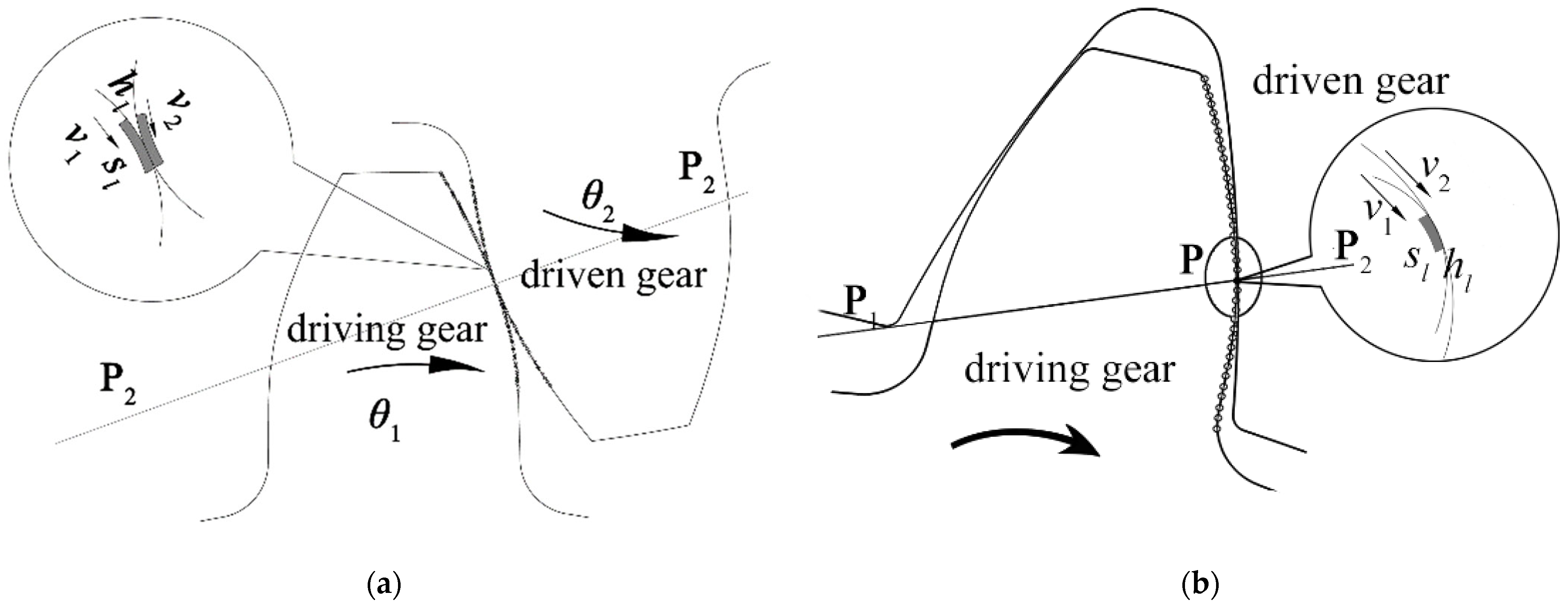
4. Modeling Gear Wear

This section proposes a model for predicting wear on gear teeth. The teeth surfaces are divided into microelements. Moreover, the wear parameters within each microelement are assumed constant. The wear depth for each microelement was calculated by applying the Archard wear theory, and the resulting wear depths were used to determine the overall distribution of wear on the gear surfaces. Wear causes changes in the backlash; consequently, the dynamic characteristics of the gear transmission mechanism change over time. Therefore, a mathematical model for predicting wear on the planetary gear is necessary for analyzing the nonlinear characteristics of the transmission system. In this study, the wear process is described from the perspective of the Archard wear theory, and it is represented by Equation (13) [56,57]
V s = K F N H
where V is the wear volume, s represents the relative sliding distance, K is a dimensionless wear coefficient, H is the hardness of the softer gear surface, and FN is the load of the surface. Taking V/A = h and FN/A = p, Equation (14) can be obtained as follows:
h s = K p H
where A is the contact area and p is the pressure.
Letting κ = K / H the wear at point P on a dry friction surface can generally be regarded as a dynamic process from the initial state. Equation (14) is then described by differential equations in Equation (15).
d h d t = κ p v
where v is the relative sliding speed and h is the wear depth. The wear depth at point P can be obtained from the integral of Equation (15). Therefore, the wear depth is formulated as Equation (16).
h p = 0 t κ p v   dt
To analyze the wear distribution on gear surfaces, the surface was divided into many microelements. In each microelement, κ and p are constant. Equation (16) is then transformed to Equation (17).
h i , j = h i , j 1 + κ p i , j 1 v i , j 1 Δ t
where i is the number of elements, j is the mesh time, and Δt is the time step. The progress of gear wear is described in Figure 5: v1 and v2 are the tangent velocities of the driving and driven gears, respectively, and P1P2 is a mesh line.

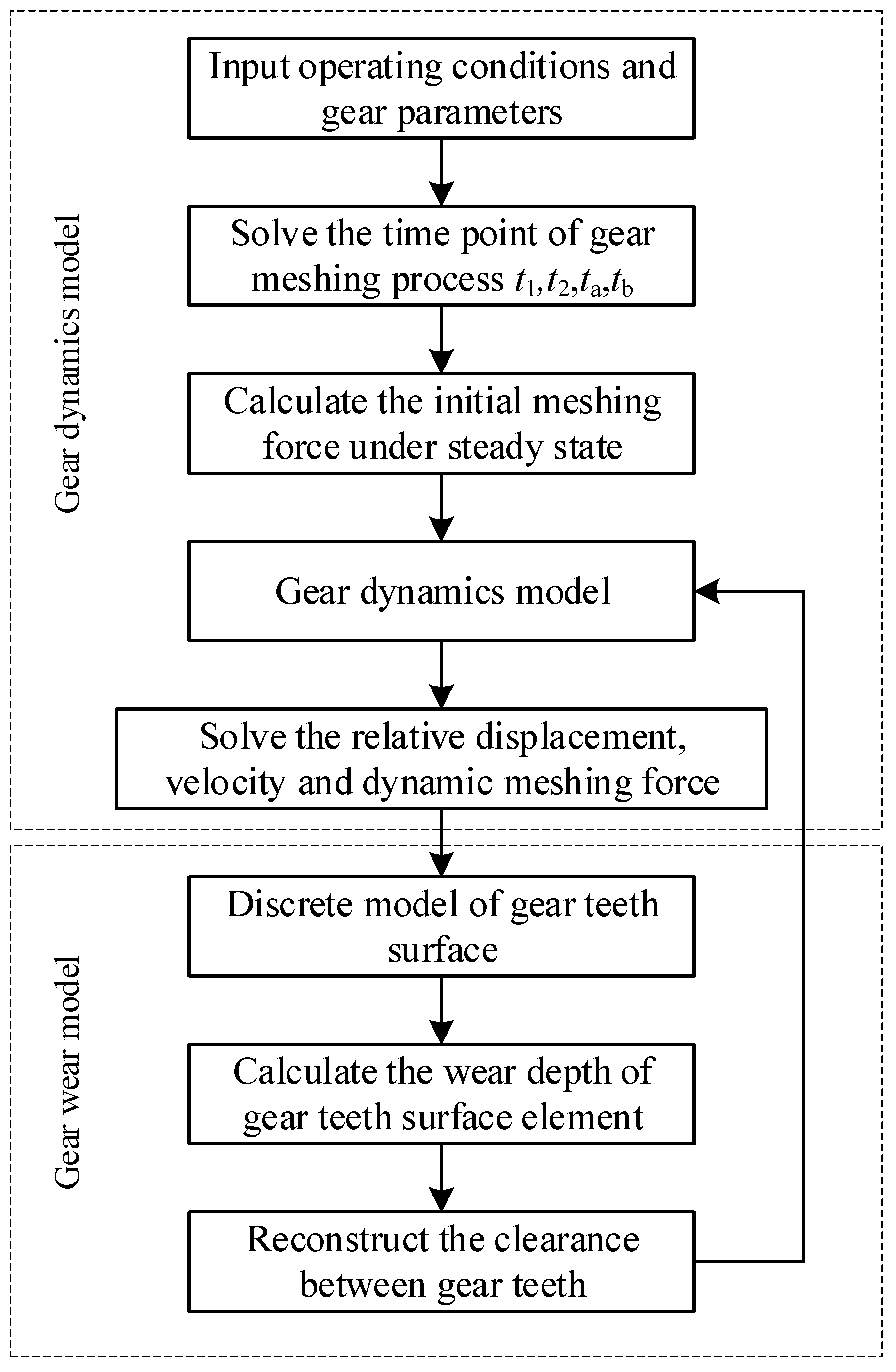
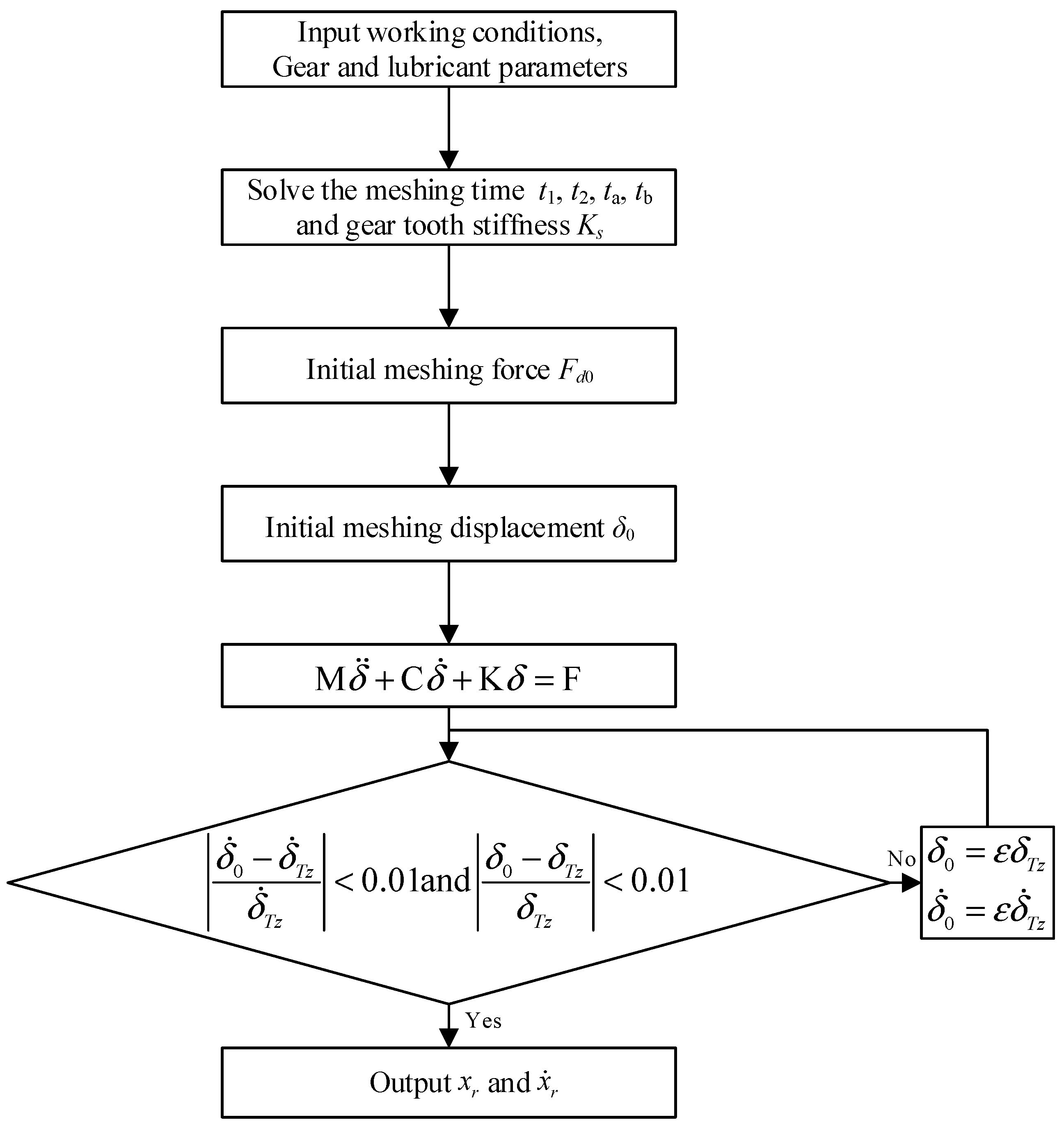
5. Wear Prediction Process

This section presents the methodology for calculating the wear distribution and dynamic responses of the planetary gear mechanism, and a numerical calculation of the wear depth and dynamic response is proposed. Further, a detailed procedure for calculating dynamic responses is discussed. A numerical case study is also presented. For each pair of teeth, a meshing cycle consists of one complete mesh period, which is determined by the rotational speed and the number of teeth. For each meshing cycle, the mesh begins at time t1 and ends at time t2. The double-tooth meshing period within one meshing cycle occurs between ta and tb. Thereafter, the surface microelements can be represented in time increments. The next step after obtaining the microelements is calculating the initial mesh force. Equation (18) presents the relationship between F and Ks according to PMPE.
U = 1 K s F 2 b
where U is a constant denoting the meshing potential energy. Thus, the mesh forces of each tooth pair are inversely proportional to their stiffness. The load ratio LR of each tooth pair can then be expressed as Equation (19).
L R ( ξ ) = F ( ξ ) F = K s ( ξ ) j = 0 n z 1 K s ( ξ + j )
The initial mesh force F d 0 is expressed as Equation (20).
F d 0 = L R ( ξ ) F
Further, the initial mesh force can be obtained by combining Equations (9) and (18)–(20). The variable mesh force can be solved from Equations (16) and (6). When variable mesh forces are introduced into the wear model, the wear distribution can be obtained. The computational process, which consists of a dynamic model and a wear model of the planetary gear mechanism, is shown in Figure 6.
The process is as follows: First, the operating conditions and initial parameters are specified to discretize the gear surface. The meshing process is then simulated, and the steady mesh forces numerically obtained, which are introduced into the dynamic model of the gear mechanism. The dynamic mesh force is then used input into the gear wear model to determine the wear depth on the gear surface. Further, the gear surface and backlash are updated based on the calculated wear depth, and the corresponding parameters of the gear dynamic model are updated accordingly. Finally, the evolution of the gear-wear depth and backlash with the number of cycles can be determined. Figure 7 presents the dynamic calculation process. The initial mesh force, mesh stiffness, and mesh instant are separately solved. In the dynamic model of the planetary gear mechanism, the Newmark-β method is employed to solve the dynamics equations. The initial distance and velocity are then obtained from the periodicity of the distance and velocity. Tz is the meshing period of the corresponding rotational speed. Finally, the initial data are obtained.
In the planetary gear system, assuming that the inputting power is 1 kW, the sun gear is the input component, and the planet-gear carrier is the output component. The geometric and material parameters of the gear mechanism are presented in Table 1.
The time-changing gear-mesh stiffness is presented in this subsection as a precondition for investigating the time-varying mesh forces. Figure 8 illustrates the variation in time-changing gear-mesh stiffness corresponding to different tooth pairs, where Tz in the time axis is the mesh period.
In Figure 8, Tz in the time axis denotes the mesh period. The peak stiffness of the single-tooth-pair mesh for both types of tooth pairs is 6.372 × 10⁶ N/m. However, in sun–planet meshing, the peak of the general tooth-pair mesh is 7.776 × 10⁶ N/m. It decreases to 7.033 × 10⁶ N/m in planet–ring meshing. The change in the overall stiffness for planet–ring meshing is less pronounced, resulting in stiffness excitation having a weaker impact on this type of meshing compared with sun–planet meshing. The gear stiffness values are listed in Table 2.

6. Numerical Results and Discussion

In this section, the distributions of wear depth on gear surfaces are first analyzed. Thereafter, the relationship between the characteristics of gear wear and rotational speeds is established. Additionally, the variation in gear vibration with mesh times is analyzed. Finally, the influence of gear wear on the vibration frequency is analyzed via FFT.

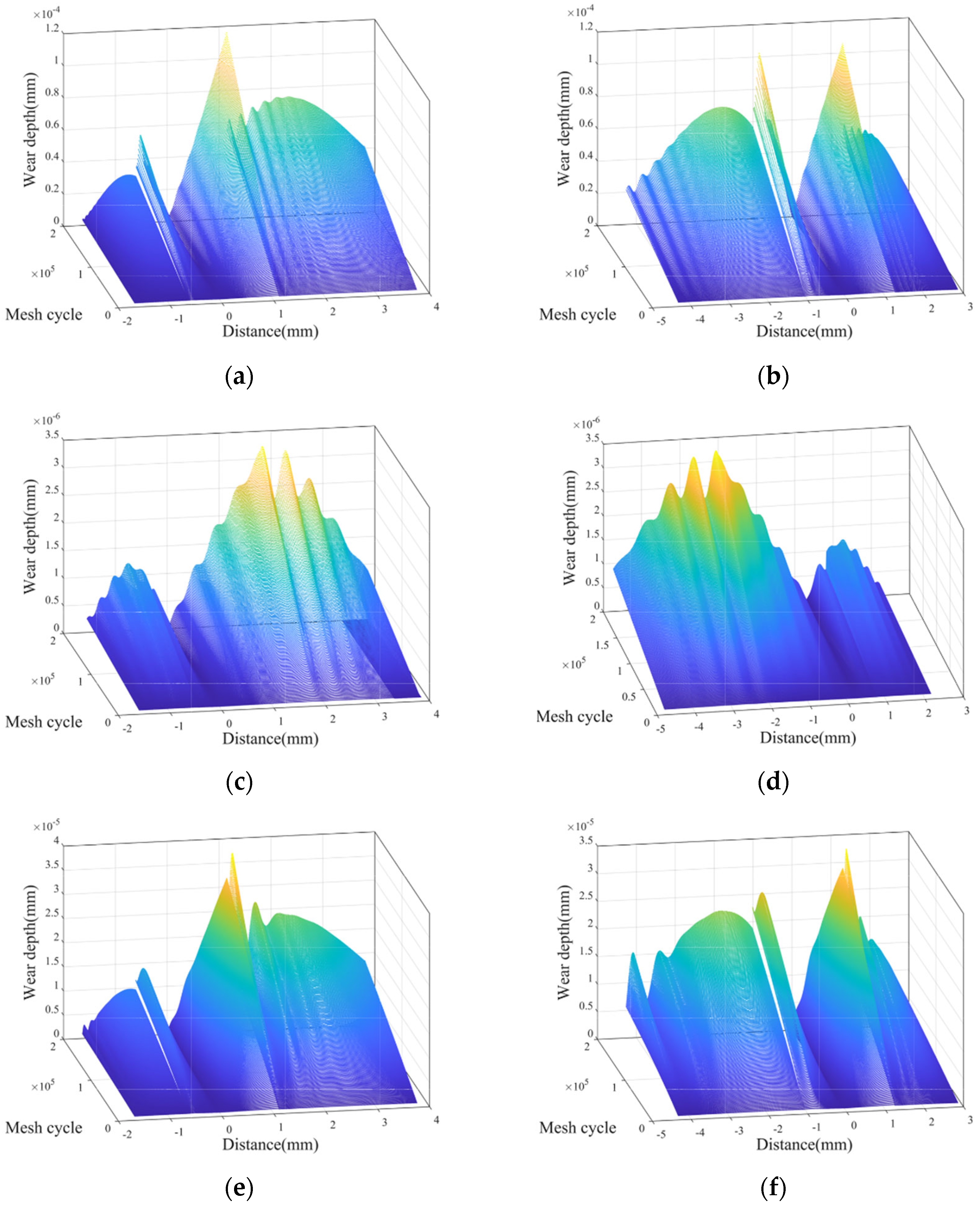
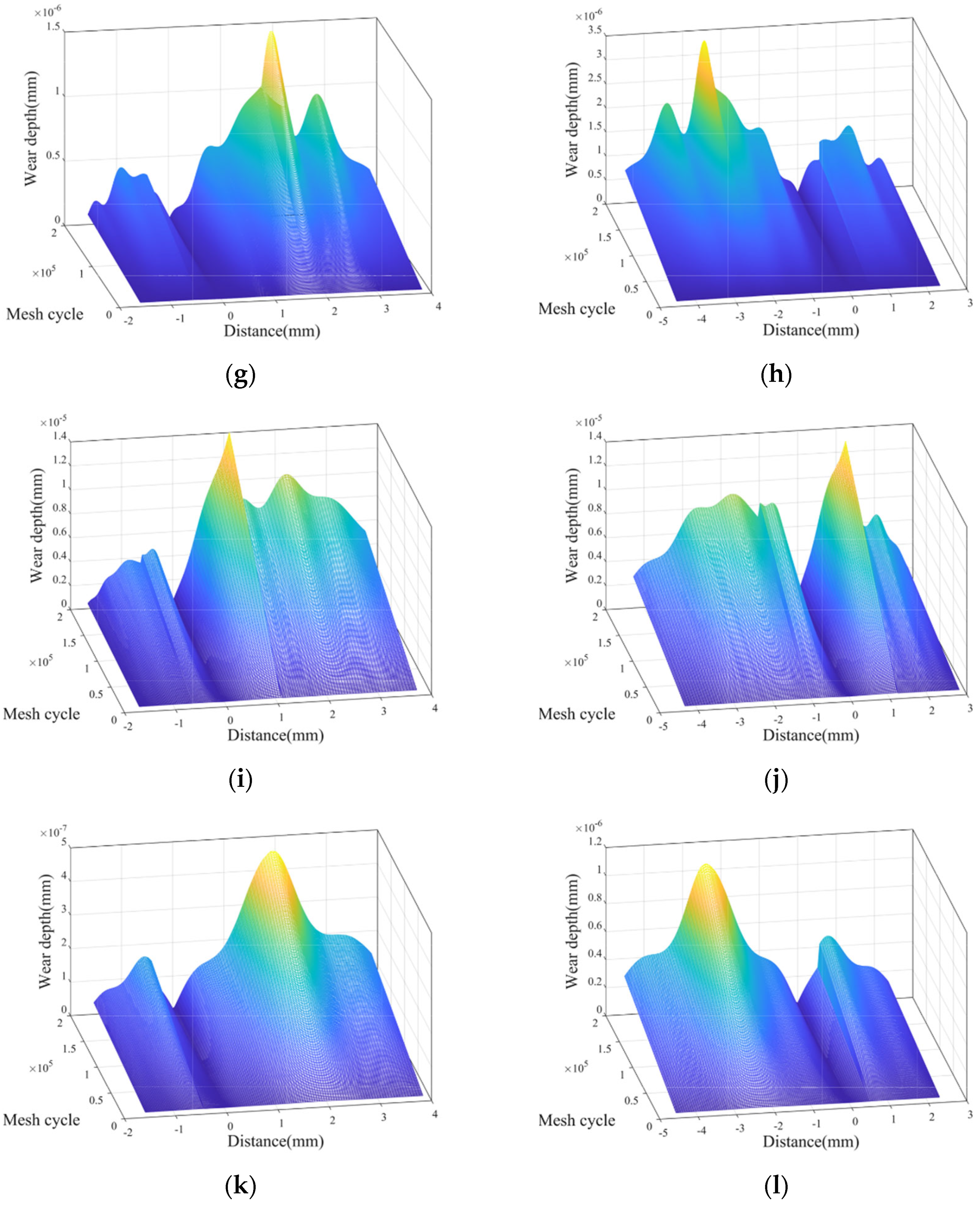
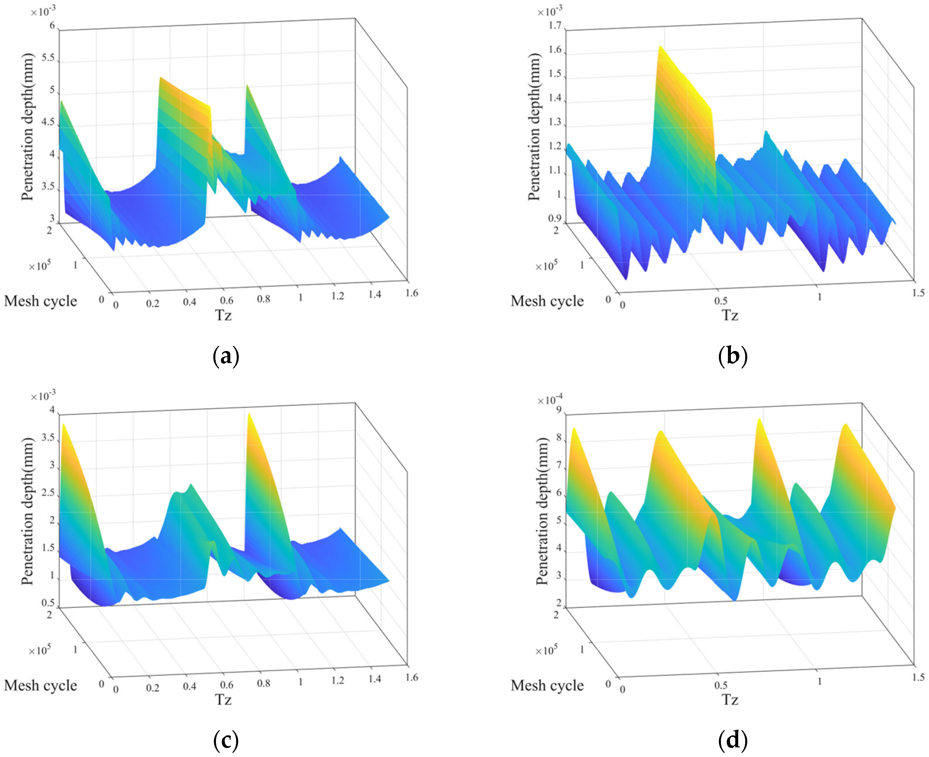
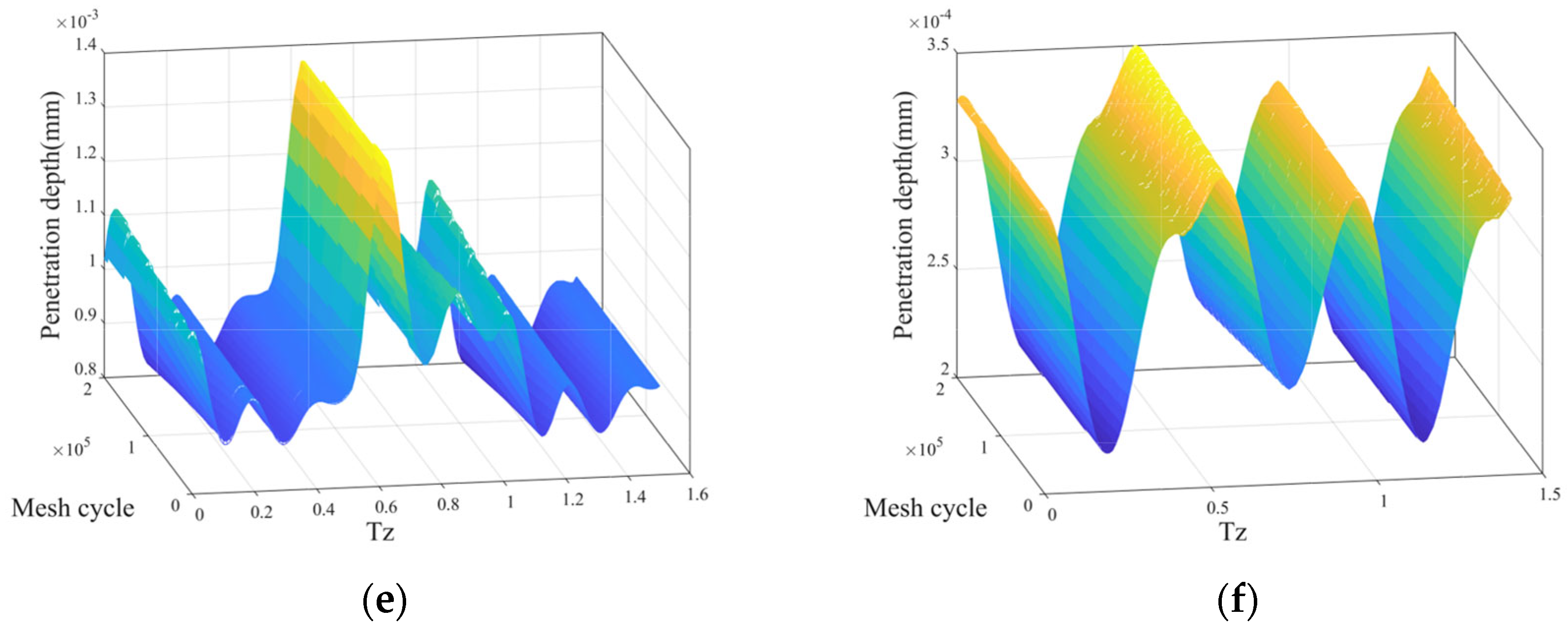
6.1. Wear Distribution

The gear mesh forces were obtained based on the gear mesh stiffness and the gear dynamic model. Here, the input power is constant. The rotational speeds were 100 rpm, 200 rpm, and 400 rpm. The variation in wear depth with gear surface at different rotational speeds as mesh time increases is shown in Figure 9.
The distance shown in Figure 9 represents the span between each point on the gear surface and the pitch curve. The negative distance denotes the point at the root of the gear tooth. As shown in Figure 9, the wear depth of the sun–planet tooth pair is markedly larger than that of the planet–ring tooth pair. As the rotational speed increased from 100 rpm to 400 rpm, the maximum wear depth of the sun–planet teeth decreased by approximately 87.93% (from 1.1610 × 10⁻⁴ mm to 1.410 × 10⁻⁵ mm) after a mesh time of 2 × 10⁵. The maximum wear depth of the planet–ring teeth decreased by 67.70% after 2 × 10⁵ meshing cycles. Because the input power is constant, the gear torque decreases linearly when the rotational speed is increased linearly. However, the maximum wear depth decreases nonlinearly. The nonlinear relationship between wear depth and mesh time is more pronounced when the rotational speed is 200 rpm because the combined effects of rotational speeds, torque, and gear rotational speed are different at different rotational speeds. As the rotational speed increases, it primarily comes under the effect of wear depth. The wear depth of the internal mesh is 3% of the external mesh when the rotational speed is 100 rpm. As the rotational speed increases to 400 rpm, the ratio increases to 6.5%. The wear characteristics of the gear mechanism will be improved with the increase of rotational speed. Generally, the distributions of wear depth become smoother as the rotational speed increases. The distribution characteristics illustrate that gear shocks are suppressed with increasing rotational speed. Comparisons of different tooth pairs revealed that the planet–ring tooth pair has better shock and wear resistance. The planet–ring tooth pair has weaker stiffness excitation and lower sliding speeds, making it more advantageous.

6.2. Dynamic Characteristics

The penetration depth at the meshing line is responsible for the gear interactions. The trend of dynamic performance as the number of mesh cycles increases should be analyzed to elucidate the relationship between gear wear and dynamic characteristics. Figure 10 shows the variation in penetration depth at the meshing line with increasing mesh cycles at different rotational speeds.
As shown in Figure 10, the amplitude of the penetration depth at the meshing line increases significantly when the mesh time increases. The shocks caused by the stiffness excitations were strengthened as the mesh time increased. The penetration depth at the meshing line in Figure 10c,d has a nonlinear relationship with the meshing time. The penetration-depth amplitude first decreased and then increased at 200 rpm. Further, the point at which the penetration depth peak occurred was delayed as the number of mesh cycles increased because increasing the wear depth at an early stage is equivalent to modifying the gear teeth. This smooths the meshing and causes a lag in the contact point. However, when the wear depth increases ulteriorly, the backlash damages the gear meshing, thus increasing the amplitude. Comparisons of penetration depth at different rotational speeds reveal that the shock in the tooth pair is suppressed as the rotational speed increases. This is attributable to decreases in torque and enhanced rotor dynamic characteristics when the rotational speed increases. Additionally, the time of dissipation was shortened, resulting in stable vibration. Comparison of the penetration depths of different tooth pairs reveal that the amplitudes of the penetration depth of the planet–ring tooth pair decreased about 72.94% compared with those of the sun–planet tooth pair. The results of the penetration depth at the meshing line correspond with those of the wear depth.
When combining the stiffness of the gear meshing with the penetration depth, the mesh force should be calculated. The acceleration of gear meshing is useful data for assessing the meshing condition and state, as well as for determining a healthy level of gear meshing. This acceleration information is depicted in Figure 11.
The acceleration-gear meshing in Figure 11 exhibits similar shock characteristics as those in Figure 10. However, the gear shocks are more marked than those shown in Figure 10. At a rotational speed of 100 rpm, as mesh time linearly increases, the amplitude of the acceleration increases at a faster rate. When the rotational speed is 200 rpm, as mesh times increase linearly, the amplitude of the acceleration increases at a slower rate. The gear accelerations exhibit nonlinear characteristics when the rotational speed increases. The gear wear increases at a high rotational speed. For different tooth pairs, the shocks in the planet–ring tooth pair were weaker than those in the sun-planet tooth pair. Three gear shocks were present in both types of tooth pairs because the second stiffness excitation in both types of tooth pairs was coincident. Notably, the two meshing types interacted.
FFT was employed to analyze the frequency information in the gear vibrations, and it showed the changes in amplitude at different frequencies when the mesh time was increased.
In Figure 12, the acceleration-vibration frequency and amplitude of the planet–ring meshing gears are lower and smaller. Compared with those of the sun–planet tooth pairs, planet–ring tooth pairs are less affected by wear. At 100 rpm, the amplitude of the acceleration vibration initially decreases and then increases as the mesh time increases. However, the amplitude always decreases at 200 rpm and 400 rpm. This suggests that at low rotational speeds, early-stage gear wear reduces the acceleration vibration at the main frequency due to the strong meshing force and wear speed. Further, as the rotational speed increases, the main frequency of acceleration vibration for sun–planet meshing increases from 450 Hz to 550 Hz, whereas the main frequency for planet–ring meshing increases from 250 Hz to 650 Hz. The low-frequency band is always in the range of 112–120 Hz and does not change with the rotational speed. This phenomenon can be attributed to the main frequency of acceleration vibration being determined by the rotational speed and the low frequency of acceleration vibration by the natural frequency. The amplitude of acceleration vibration at 200 rpm is the largest of the three cases. The amplitude of the low-frequency band increases significantly. The greater the difference between the meshing frequency and the natural frequency, the weaker the effect on the gear acceleration vibration after wear.

6.3. Discussion

From the result and analysis, the planet–ring meshing shows the benefit of wear and impact resistance. The wear depth of planet–ring meshing is smaller than 10% of the wear depth of sun–planet meshing. The amplitudes of penetration depth of the planet–ring tooth pair are about 27.06% of those of the sun–planet tooth pair. The maximum amplitude of the acceleration vibration of planet–ring meshing is about 11.86% that of sun–planet meshing.
The rotational speed increased from 100 rpm to 400 rpm, and the maximum wear depth of the sun–planet teeth decreased by approximately 87.93% (from 1.1610 × 10⁻⁴ mm to 1.410 × 10⁻⁵ mm) after mesh times of 2 × 10⁵. The maximum wear depth of the planet–ring teeth decreased by 67.70% after 2 × 10⁵ meshing times. That is due to the input power being constant, and the lower rotational speed leads to a higher torque. The wear and the dynamic characteristics of gear mechanisms are phenomena. Additionally, the nonlinear characteristics are more remarkable at 200 rpm. The acceleration amplitude of FFT increases by about 102.11%.

7. Conclusions

A computational methodology for the dynamic responses of a planetary gear mechanism that considers dynamic wear effects is proposed in this study. The nonlinear parameters, namely the gear stiffness, gear backlash, and gear wear distribution are considered in the investigation. The method combines the wear model and the dynamic model of the gear mechanism to analyze the relationship between gear surface wear and gear dynamic responses. The numerical results reveal the influences of wear on the dynamic responses of the gear. The main conclusions are drawn as follows:
  • According to the wear distribution of the planetary gear, the wear corresponding to sun–planet meshing is more severe. The wear in planet–ring meshing represents less fluctuation, which suggests better wear resistance. Because the driven gears have higher sliding speeds during meshing, the driven gears exhibit greater wear depths. The dynamic performance of the gear rapidly deteriorates as the wear depth of the tooth surface increases.
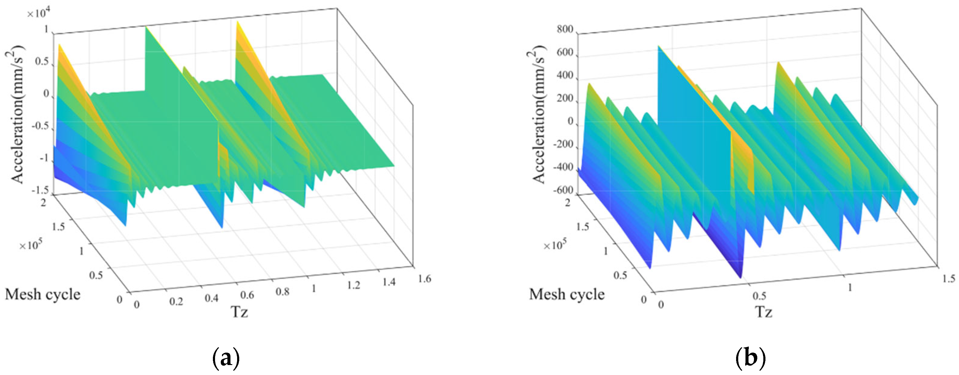
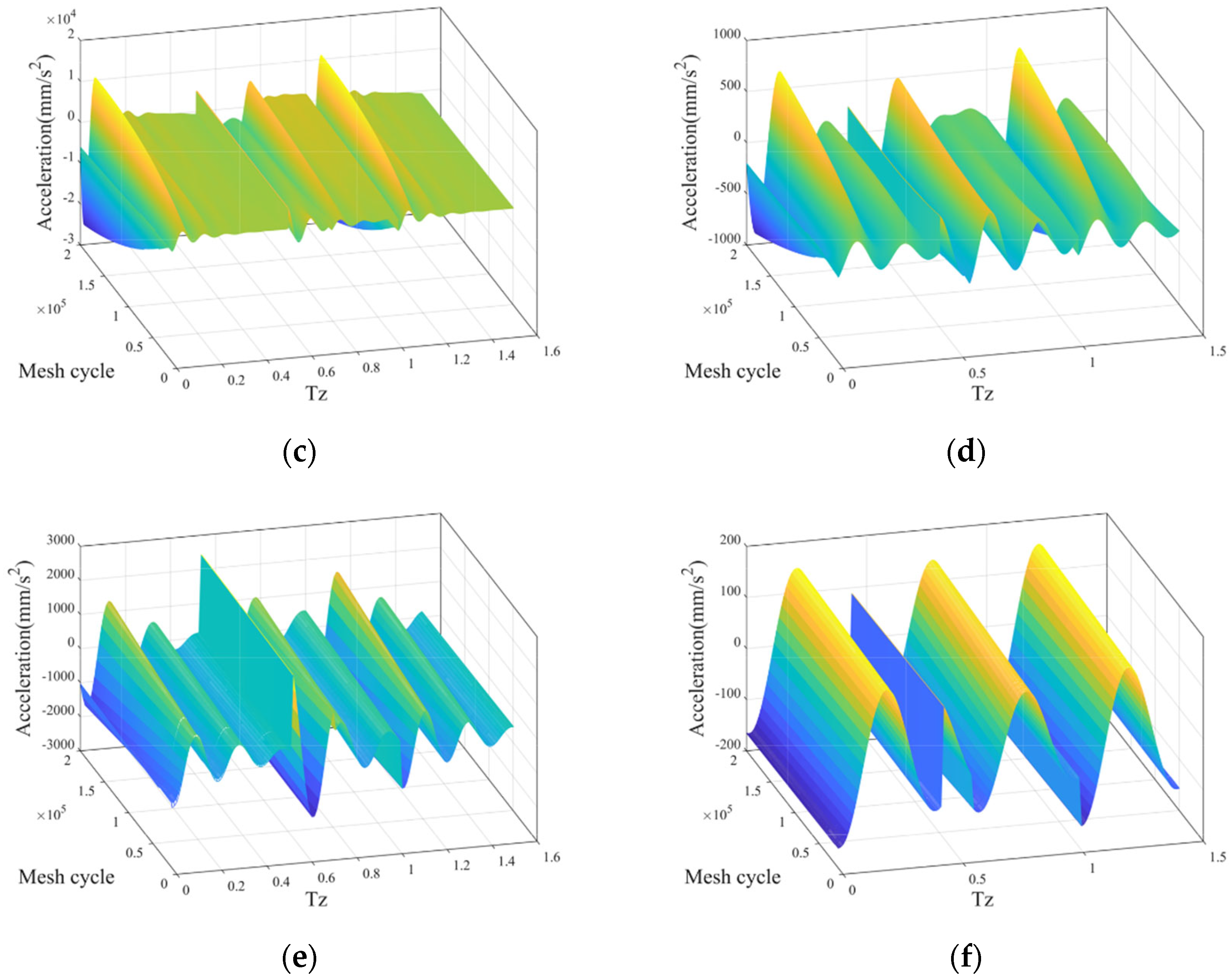
  • The gear-meshing vibration at a low rotational speed exhibits a nonlinear relationship with mesh time, which is due to the coupling among the dynamic characteristics, mesh force, and sliding speed. As rotational speed increases, the nonlinear characteristic deteriorates, which is due to sliding speed becoming the main influencing factor.
  • The analysis of gear wear, vibration responses, and the frequency spectra reveal that planet–ring meshing exhibits better wear and shock resistance than sun–planet meshing. This leads to frequent failure of the sun gear, which is consistent with practical engineering experience. Therefore, increasing the maintainability of the sun gear will improve the service life of the planetary gear mechanism.
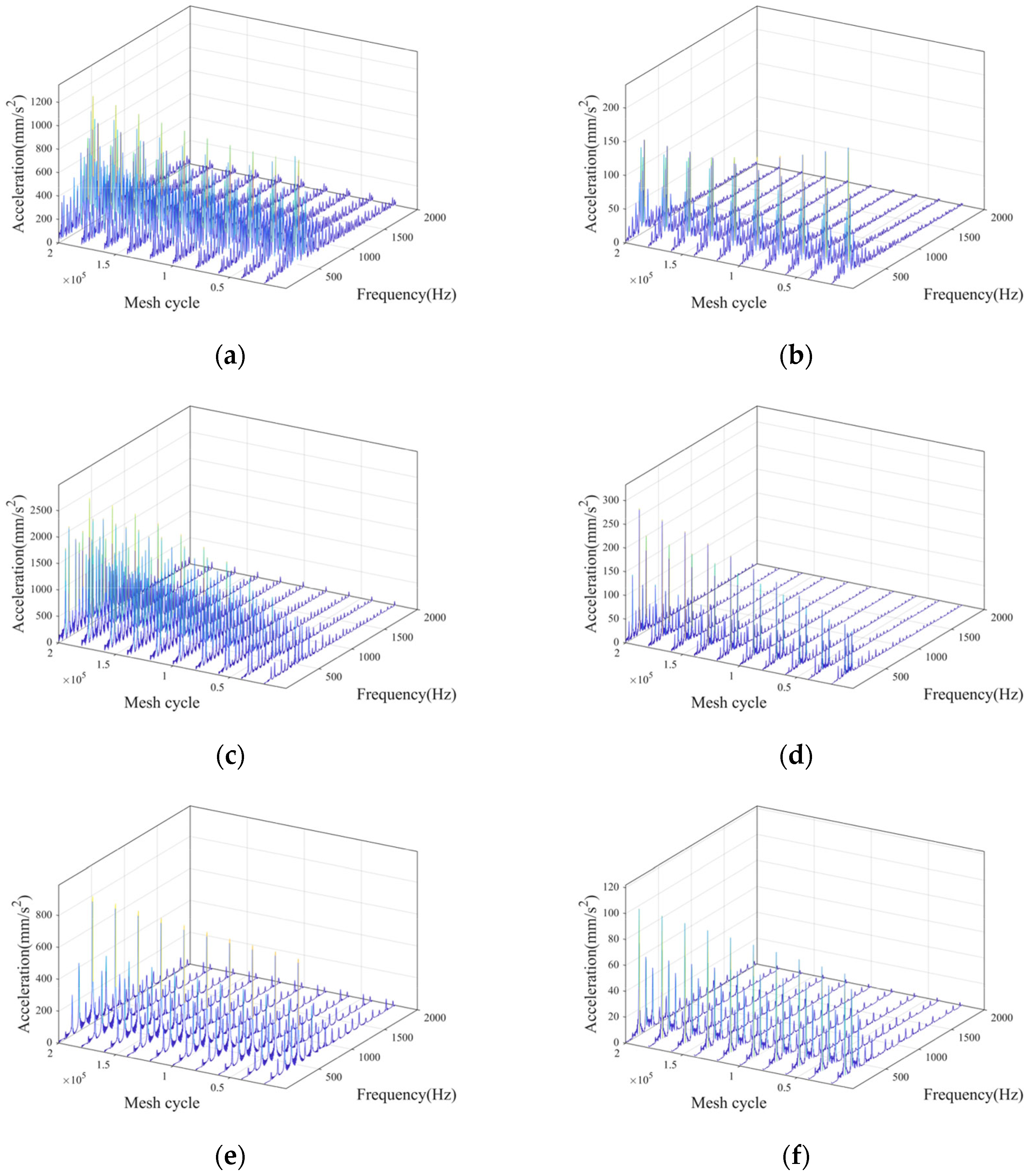
  • At different rotational speeds, gear wear has different effects on the amplitude of the main frequency. The adverse effects of planetary-gear wear on planetary-gear vibra-tion can be effectively mitigated by selecting an appropriate rotational speed, and the gear vibration can be improved through early gear wear.
The wear of the planetary gear mechanism exhibits different characteristics at different types of meshing. The sun–planet meshing degenerates rapidly, so special care is required to increase wear resistance. The rotational speed exhibits a stronger influence at a low rotational speed; thus, such a rotational speed should be avoided to weaken the nonlinear characteristics. Studying the dynamic responses of the planetary gear mechanism by considering dynamic wear effects provides a guideline for designing and predicting the life of planetary gear mechanisms.

Author Contributions

Conceptualization, Z.B. and Z.N.; investigation, Z.B. and Z.N.; writing—original draft preparation, Z.N.; writing—review and editing, Z.B. and Z.N.; supervision, Z.B. All authors have read and agreed to the published version of the manuscript.

Funding

This work is supported by the National Natural Science Foundation of China (Grant Nos. U21B2075, 51775128).

Data Availability Statement

Not applicable.

Conflicts of Interest

The authors declare no conflict of interest.

Nomenclature

AContact area
CsEquivalent correction factor
cspSun-planet tooth profile meshing damping
cprPlanet-ring tooth profile meshing damping
EElasticity modulus
eprPlanet-ring meshing error
espSun-planet meshing error
FcDamping force
FNLoad force
fFrictional force
GShear modulus
HHardness of soft surface
hWear depth
IcInertial moment of planet gear carrier
IpInertial moment of the planet gear
IsInertial moment of the sun gear
KHContact stiffness
KsMesh stiffness
knAxial compressive stiffness
ksShear stiffness
kxBending stiffness
LRLoad ratio
MEquivalent mass
mcMass of planet gear carrier
mpMass of planet gear
msMass of sun gear
pPressure
RcRotation radius of planet gear carrier
RpThe basic radius of planet gear
RsThe basic radius of the sun gear
SEquivalent curvature radius of tooth surface
sSliding distance
TcTorque of planet gear carrier
TsTorque of sun gear
TpTorque of planet gear
UGear meshing potential energy
VWear volume
vSliding velocity
zTooth number
αPressure angle
γpAngle thickness at point P
δMeshing penetration depth
εChordal thickness
ΔtTime step
ζWear coefficient
θcRotational displacement of planet gear carrier
θpRotational displacement of planet gear
θsRotational displacement of sun gear
κDimensionless wear coefficient

References

  1. Kahraman, A.; Singh, R. Non-Linear Dynamics of a Spur Gear Pair. J. Sound Vib. 1990, 142, 49–75. [Google Scholar] [CrossRef]
  2. Kahraman, A.; Singh, R. Interactions between Time-Varying Mesh Stiffness and Clearance Non-Linearities in a Geared System. J. Sound Vib. 1991, 146, 135–156. [Google Scholar] [CrossRef]
  3. Kahraman, A. Free Torsional Vibration Characteristics of Compound Planetary Gear Sets. Mech. Mach. Theory 2001, 36, 953–971. [Google Scholar] [CrossRef]
  4. Kahraman, A. Planetary Gear Train Dynamics. J. Mech. Des. 1994, 116, 713–720. [Google Scholar] [CrossRef]
  5. Parker, R.G.; Vijayakar, S.M.; Imajo, T. Non-Linear Dynamic Response of a Spur Gear Pair: Modelling and Experimental Comparisons. J. Sound Vib. 2000, 237, 435–455. [Google Scholar] [CrossRef] [Green Version]
  6. Parker, R.G.; Lin, J. Mesh Phasing Relationships in Planetary and Epicyclic Gears. J. Mech. Des. 2004, 126, 365–370. [Google Scholar] [CrossRef]
  7. Ambarisha, V.K.; Parker, R.G. Nonlinear Dynamics of Planetary Gears Using Analytical and Finite Element Models. J. Sound Vib. 2007, 302, 577–595. [Google Scholar] [CrossRef]
  8. Huang, Y. Mathematical model of planetary gear sets’ vibration signal and characteristic frequency analysis. J. Mech. Eng. 2016, 52, 46. [Google Scholar] [CrossRef]
  9. Wang, C.C. Rotational Vibration with Backlash: Part 1. J. Mech. Des. 1978, 100, 363–373. [Google Scholar] [CrossRef]
  10. Wang, C.C. Rotational Vibration with Backlash: Part 2. J. Mech. Des. 1981, 103, 387–397. [Google Scholar] [CrossRef]
  11. Özgüven, H.N.; Houser, D.R. Mathematical Models Used in Gear Dynamics—A Review. J. Sound Vib. 1988, 121, 383–411. [Google Scholar] [CrossRef]
  12. Shi, J.; Gou, X.; Zhu, L. Modeling and Analysis of a Spur Gear Pair Considering Multi-State Mesh with Time-Varying Parameters and Backlash. Mech. Mach. Theory 2019, 134, 582–603. [Google Scholar] [CrossRef]
  13. Al-Shyyab, A.; Kahraman, A. A Non-Linear Dynamic Model for Planetary Gear Sets. Proc. Inst. Mech. Eng. Part K J. Multi-Body Dyn. 2007, 221, 567–576. [Google Scholar] [CrossRef]
  14. Lin, J.; Parker, R.G. Analytical Characterization of the Unique Properties of Planetary Gear Free Vibration. J. Vib. Acoust. 1999, 121, 316–321. [Google Scholar] [CrossRef]
  15. Lin, J.; Parker, R.G. Sensitivity of Planetary Gear Natural Frequencies and Vibration Modes to Model Parameters. J. Sound Vib. 1999, 228, 109–128. [Google Scholar] [CrossRef]
  16. Xiang, L.; Gao, N.; Hu, A. Dynamic Analysis of a Planetary Gear System with Multiple Nonlinear Parameters. J. Comput. Appl. Math. 2018, 327, 325–340. [Google Scholar] [CrossRef]
  17. Ligata, H.; Kahraman, A.; Singh, A. An Experimental Study of the Influence of Manufacturing Errors on the Planetary Gear Stresses and Planet Load Sharing. J. Mech. Des. 2008, 130, 041701. [Google Scholar] [CrossRef]
  18. Ligata, H.; Kahraman, A.; Singh, A. A Closed-Form Planet Load Sharing Formulation for Planetary Gear Sets Using a Translational Analogy. J. Mech. Des. 2009, 131, 021007. [Google Scholar] [CrossRef]
  19. He, G.; Ding, K.; Wu, X.; Yang, X. Dynamics Modeling and Vibration Modulation Signal Analysis of Wind Turbine Planetary Gearbox with a Floating Sun Gear. Renew. Energy 2019, 139, 718–729. [Google Scholar] [CrossRef]
  20. Dong, H.L.; Hu, J.B.; Li, X.Y. Temperature Analysis of Involute Gear Based on Mixed Elastohydrodynamic Lubrication Theory Considering Tribo-Dynamic Behaviors. J. Tribol. 2014, 136, 021504. [Google Scholar] [CrossRef]
  21. Yuan, S.H.; Dong, H.L.; Li, X.Y. Analysis of Lubricating Performance for Involute Gear Based on Dynamic Loading Theory. J. Mech. Des. 2012, 134, 121004. [Google Scholar] [CrossRef] [Green Version]
  22. Zhang, J.; Liu, S.; Fang, T. On the Prediction of Friction Coefficient and Wear in Spiral Bevel Gears with Mixed TEHL. Tribol. Int. 2017, 115, 535–545. [Google Scholar] [CrossRef]
  23. Chen, Z.; Shao, Y. Mesh Stiffness of an Internal Spur Gear Pair with Ring Gear Rim Deformation. Mech. Mach. Theory 2013, 69, 1–12. [Google Scholar] [CrossRef]
  24. Chen, Y.; Wu, X. Dynamic Load Sharing Behavior of Planetary Gear Train with Backlashes. In Proceedings of the 2009 International Conference on Engineering Computation, Hong Kong, China, 2–3 May 2009; pp. 209–212. [Google Scholar]
  25. Guo, Y.; Keller, J.; Parker, R.G. Nonlinear Dynamics and Stability of Wind Turbine Planetary Gear Sets under Gravity Effects. Eur. J. Mech. A. Solids 2014, 47, 45–57. [Google Scholar] [CrossRef]
  26. Guo, Y.; Parker, R.G. Dynamic Modeling and Analysis of a Spur Planetary Gear Involving Tooth Wedging and Bearing Clearance Nonlinearity. Eur. J. Mech. A. Solids 2010, 29, 1022–1033. [Google Scholar] [CrossRef]
  27. Guo, Y.; Parker, R.G. Analytical Determination of Mesh Phase Relations in General Compound Planetary Gears. Mech. Mach. Theory 2011, 46, 1869–1887. [Google Scholar] [CrossRef]
  28. Kim, W.; Lee, J.Y.; Chung, J. Dynamic Analysis for a Planetary Gear with Time-Varying Pressure Angles and Contact Ratios. J. Sound Vib. 2012, 331, 883–901. [Google Scholar] [CrossRef]
  29. Ma, P.; Botman, M. Load Sharing in a Planetary Gear Stage in the Presence of Gear Errors and Misalignment. J. Mech. Transm. Autom. Des. 1985, 107, 4–10. [Google Scholar] [CrossRef]
  30. Sánchez, M.B.; Pleguezuelos, M.; Pedrero, J.I. Calculation of Tooth Bending Strength and Surface Durability of Internal Spur Gear Drives. Mech. Mach. Theory 2016, 95, 102–113. [Google Scholar] [CrossRef]
  31. Sánchez, M.B.; Pleguezuelos, M.; Pedrero, J.I. Strength Model for Bending and Pitting Calculations of Internal Spur Gears. Mech. Mach. Theory 2019, 133, 691–705. [Google Scholar] [CrossRef]
  32. Siyu, C.; Jinyuan, T.; Caiwang, L.; Qibo, W. Nonlinear Dynamic Characteristics of Geared Rotor Bearing Systems with Dynamic Backlash and Friction. Mech. Mach. Theory 2011, 46, 466–478. [Google Scholar] [CrossRef]
  33. Sun, T.; Hu, H. Nonlinear Dynamics of a Planetary Gear System with Multiple Clearances. Mech. Mach. Theory 2003, 38, 1371–1390. [Google Scholar] [CrossRef]
  34. Tsai, S.-J.; Huang, G.-L.; Ye, S.-Y. Gear Meshing Analysis of Planetary Gear Sets with a Floating Sun Gear. Mech. Mach. Theory 2015, 84, 145–163. [Google Scholar] [CrossRef]
  35. Flodin, A.; Andersson, S. Simulation of Mild Wear in Spur Gears. Wear 1997, 207, 16–23. [Google Scholar] [CrossRef]
  36. Flodin, A.; Andersson, S. Simulation of Mild Wear in Helical Gears. Wear 2000, 241, 123–128. [Google Scholar] [CrossRef]
  37. Flodin, A.; Andersson, S. Wear Simulation of Spur Gears. Tribotest 1999, 5, 225–249. [Google Scholar] [CrossRef]
  38. Flodin, A.; Andersson, S. A Simplified Model for Wear Prediction in Helical Gears. Wear 2001, 249, 285–292. [Google Scholar] [CrossRef]
  39. Shen, Z.; Qiao, B.; Yang, L.; Luo, W.; Chen, X. Evaluating the Influence of Tooth Surface Wear on TVMS of Planetary Gear Set. Mech. Mach. Theory 2019, 136, 206–223. [Google Scholar] [CrossRef]
  40. Shen, Z.; Qiao, B.; Yang, L.; Luo, W.; Yan, R.; Chen, X. Dynamic Modeling of Planetary Gear Set with Tooth Surface Wear. Procedia Manuf. 2020, 49, 49–54. [Google Scholar] [CrossRef]
  41. Guerine, A.; Hami, A.E.; Walha, L.; Fakhfakh, T.; Haddar, M. Dynamic Response of a Spur Gear System with Uncertain Friction Coefficient. Adv. Eng. Softw. 2018, 120, 45–54. [Google Scholar] [CrossRef]
  42. Straffelini, G. Friction and Wear; Springer Tracts in Mechanical Engineering; Springer International Publishing: Cham, Switzerland, 2015; ISBN 978-3-319-05893-1. [Google Scholar]
  43. Li, S.; Wu, Q.; Zhang, Z. Bifurcation and Chaos Analysis of Multistage Planetary Gear Train. Nonlinear Dynam. 2014, 75, 217–233. [Google Scholar] [CrossRef]
  44. Li, S.; Anisetti, A. A Tribo-Dynamic Contact Fatigue Model for Spur Gear Pairs. Int. J. Fatigue 2017, 98, 81–91. [Google Scholar] [CrossRef]
  45. Yan, Y. Load Characteristic Analysis and Fatigue Reliability Prediction of Wind Turbine Gear Transmission System. Int. J. Fatigue 2020, 130, 105259. [Google Scholar] [CrossRef]
  46. Yan, Y.; Jiang, C.; Li, W. Simulation on Coupling Effects between Surface Wear and Fatigue in Spur Gear. Eng. Fail. Anal. 2022, 134, 106055. [Google Scholar] [CrossRef]
  47. Bajpai, P.; Kahraman, A.; Anderson, N.E. A Surface Wear Prediction Methodology for Parallel-Axis Gear Pairs. J. Tribol. 2004, 126, 597–605. [Google Scholar] [CrossRef]
  48. Yuksel, C.; Kahraman, A. Dynamic Tooth Loads of Planetary Gear Sets Having Tooth Profile Wear. Mech. Mach. Theory 2004, 39, 695–715. [Google Scholar] [CrossRef]
  49. Ding, H.; Kahraman, A. Interactions between Nonlinear Spur Gear Dynamics and Surface Wear. J. Sound Vib. 2007, 307, 662–679. [Google Scholar] [CrossRef]
  50. Wu, S.; Cheng, H.S. Sliding Wear Calculation in Spur Gears. J. Tribol. 1993, 115, 493–500. [Google Scholar] [CrossRef]
  51. Zhou, C.; Wang, H. An Adhesive Wear Prediction Method for Double Helical Gears Based on Enhanced Coordinate Transformation and Generalized Sliding Distance Model. Mech. Mach. Theory 2018, 128, 58–83. [Google Scholar] [CrossRef]
  52. Choy, F.K.; Polyshchuk, V.; Zakrajsek, J.J.; Handschuh, R.F.; Townsend, D.P. Analysis of the Effects of Surface Pitting and Wear on the Vibration of a Gear Transmission System. Tribol. Int. 1996, 29, 77–83. [Google Scholar] [CrossRef]
  53. Wojnarowski, J.; Onishchenko, V. Tooth Wear Effects on Spur Gear Dynamics. Mech. Mach. Theory 2003, 38, 161–178. [Google Scholar] [CrossRef]
  54. Zhang, H.; Shen, X. A Dynamic Tooth Wear Prediction Model for Reflecting “Two-Sides” Coupling Relation between Tooth Wear Accumulation and Load Sharing Behavior in Compound Planetary Gear Set. Proc. Inst. Mech. Eng. Part C J. Mech. Eng. Sci. 2020, 234, 1746–1763. [Google Scholar] [CrossRef]
  55. Feng, K.; Borghesani, P.; Smith, W.A.; Randall, R.B.; Chin, Z.Y.; Ren, J.; Peng, Z. Vibration-Based Updating of Wear Prediction for Spur Gears. Wear 2019, 426–427, 1410–1415. [Google Scholar] [CrossRef]
  56. Salib, J.; Kligerman, Y.; Etsion, I. A Model for Potential Adhesive Wear Particle at Sliding Inception of a Spherical Contact. Tribol. Lett. 2008, 30, 225–233. [Google Scholar] [CrossRef]
  57. Hanief, M.; Charoo, M.S. Archard’s Wear Law Revisited to Measure Accurate Wear Coefficient Considering Actual Sliding Velocity. Mater. Today Proc. 2021, 47, 5598–5600. [Google Scholar] [CrossRef]
Figure 1. Components of the planetary gear.
Lubricants 11 00255 g001
Figure 2. Coordinate systems and parameters of the planetary gear system.
Lubricants 11 00255 g002
Figure 3. Contact forces of tooth pairs at gear meshing. (a) Forces acting during single-tooth pair meshing at the sun–planet gears. (b) Forces acting during single-tooth pair meshing at the planet–ring gears. (c) Forces acting during double-tooth pair meshing at the sun–planet gears. (d) Forces acting during double-tooth pair meshing at the planet–ring gears.
Lubricants 11 00255 g003
Figure 4. Calculation parameters of gear-tooth stiffness: (a) Internal ring gear parameters. (b) External gear parameters.
Lubricants 11 00255 g004
Figure 5. Wear process in planetary gear: (a) Wear process in a sun–planet tooth pair. (b) Wear process in a planet–ring tooth pair.
Lubricants 11 00255 g005
Figure 6. Procedure for dynamics and wear analysis of the gear mechanism.
Lubricants 11 00255 g006
Figure 7. Calculation process for the initial data.
Lubricants 11 00255 g007
Figure 8. Mesh stiffness of gear mesh pairs: (a) Mesh stiffness of a sun–planet tooth pair. (b) Mesh stiffness of a planet–ring tooth pair.
Lubricants 11 00255 g008
Figure 9. Wear distribution on tooth surface: (a) Sun-gear wear distribution in a sun–planet tooth pair (100 rpm). (b) Planet-gear wear distribution in a sun–planet tooth pair (100 rpm). (c) Planet-gear wear distribution in a planet–ring tooth pair (100 rpm). (d) Internal-ring-gear wear distribution in a planet–ring tooth pair (100 rpm). (e) Sun-gear wear distribution in a sun–planet tooth pair (200 rpm). (f) Planet-gear wear distribution in a sun–planet tooth pair (200 rpm). (g) Planet-gear wear distribution in a planet–ring tooth pair (200 rpm). (h) Internal-ring-gear wear distribution in a planet–ring tooth pair (200 rpm). (i) Sun-gear wear distribution in a sun–planet tooth pair (400 rpm). (j) Planet-gear wear distribution in a sun–planet tooth pair (400 rpm). (k) Planet-gear wear distribution in a planet–ring tooth pair (400 rpm). (l) Internal-ring-gear wear distribution in a planet–ring tooth pair (400 rpm).
Lubricants 11 00255 g009aLubricants 11 00255 g009b
Figure 10. Penetration depth at the meshing line: (a) Sun–planet gear-penetration depth at the meshing line (100 rpm). (b) Planet–ring gear-penetration depth at the meshing line (100 rpm). (c) Sun–planet gear-penetration depth at the meshing line (200 rpm). (d) Planet–ring gear-penetration depth at the meshing line (200 rpm). (e) Sun–planet gear-penetration depth at the meshing line (400 rpm); (f) Planet–ring gear-penetration depth at the meshing line (400 rpm).
Lubricants 11 00255 g010aLubricants 11 00255 g010b
Figure 11. Acceleration at the meshing line: (a) Sun–planet gear acceleration at the meshing line (100 rpm). (b) Planet–ring gear acceleration at the meshing line (100 rpm). (c) Sun–planet gear acceleration at the meshing line (200 rpm). (d) Planet–ring gear acceleration at the meshing line (200 rpm). (e) Sun–planet gear acceleration at the meshing line (400 rpm). (f) Planet–ring gear acceleration at the meshing line (400 rpm).
Lubricants 11 00255 g011aLubricants 11 00255 g011b
Figure 12. FFT of gear-meshing acceleration vibration at the meshing line: (a) Acceleration spectrum of sun–planet meshing (100 rpm). (b) Acceleration spectrum of planet–ring meshing (100 rpm). (c) Acceleration spectrum of sun–planet meshing (200 rpm). (d) Acceleration spectrum of planet–ring meshing (200 rpm). (e) Acceleration spectrum of sun–planet meshing (400 rpm). (f) Acceleration spectrum of planet–ring meshing (400 rpm).
Lubricants 11 00255 g012
Table 1. The geometric and material parameters of the gear mechanism.
ParametersValue
Modules/mm3
Tooth number of the internal ring gear81
Tooth number of the planet gear30
Tooth number of the sun gear21
Meshing angle/rad0.349066
Gear width/mm50
Elasticity modulus of internal ring gear E1/GPa206
Elasticity modulus of planet gear E2/GPa206
Elasticity modulus of sun gear E3/GPa206
Shear modulus of internal ring gear G1/GPa79.4
Shear modulus of planet gear G2/GPa79.4
Shear modulus of sun gear G3/GPa79.4
Poisson ratio of internal ring gear0.3
Poisson of planet gear0.3
Poisson of the sun gear0.3
Dynamic friction coefficient0.1
Wear coefficient K5 × 10−11
Table 2. Data on gear stiffness.
ParameterSun–PlanetPlanet–Ring
Max. single stiffness 6.372 × 10⁶ N/m6.372 × 106 N/m
Max. general stiffness 7.776 × 10⁶ N/m7.033 × 106 N/m
First stiffness excitation1.558 × 106 N/m1.561 × 106 N/m
Disclaimer/Publisher’s Note: The statements, opinions and data contained in all publications are solely those of the individual author(s) and contributor(s) and not of MDPI and/or the editor(s). MDPI and/or the editor(s) disclaim responsibility for any injury to people or property resulting from any ideas, methods, instructions or products referred to in the content.

