Article

Research on Lubrication Characteristics of Cage-Free Ball Bearing with Local Functional Slot

Key Laboratory of Advanced Manufacturing and Intelligent Technology, Harbin University of Science and Technology, Ministry of Education, Harbin 150080, China
*
Author to whom correspondence should be addressed.
Lubricants 2023, 11(5), 203; https://doi.org/10.3390/lubricants11050203
Submission received: 16 March 2023 / Revised: 25 April 2023 / Accepted: 1 May 2023 / Published: 2 May 2023

Abstract

:
The factors affecting the lubrication effect of a ball bearing without cage and containing a functional slot are analyzed, including the structural parameters of the functional slot, the speed of the rolling element, and the deformation of the contact surface, in order to establish the initial oil volume equation. Based on the multiple mesh method and Matlab programming, the established model is solved by obtaining the distribution rules of oil film pressure, oil film thickness, and oil film flow rate between the rolling element, the conventional raceway, and the functional slot under different speed conditions, and by determining the optimal functional slot depth. Finally, through an experiment performed to verify the lubrication effect of the lubricating oil in the functional slot, the results show that the lubricating oil in the functional slot can have a lubricating effect, and the initial amount of lubricating oil needed increases with an increase in speed.

1. Introduction

Lubrication is very important to increase the service life of mechanism parts; under-lubrication or over-lubrication will affect their performance and even cause material wear, resulting in parts that cannot be used [1,2,3]. Between 1976 and 1977, Hanmrock and Dowson published four consecutive articles on point contact elastohydrodynamic lubrication [4,5,6] through the analysis of speed, load, ellipticity, lack of oil, and other factors on the influence of oil film thickness, and finally derived the minimum oil film thickness formula in the elliptical region of point contact. In 1985, the Chinese scholar Yang proposed to apply the theory of elastohydrodynamic lubrication to rolling ball bearings [7], while combining the elastohydrodynamic lubrication theory and the oil film thickness formula for a simplified solution, given the rolling ball bearing oil film pressure and oil film thickness distribution law, and the difference between the calculation results and experimental errors was very small, to verify the feasibility of the theory of elastohydrodynamic lubrication in rolling ball bearings. Since then, many scholars began to analyze the rolling ball bearing lubrication problem. Liu et al. established a dynamic model for angular contact bearing while considering the temperature generated during lubrication and the influence of lubricant type on the bearing dynamic characteristics [8]; the results showed that an increase in lubricant temperature would lead to an increase in slippage between the rolling body and raceway, but it would reduce the collision between the rolling body and cage, while considering different types of lubricants with different factors, such as viscosity and density, which would also lead to changes in the motion of the rolling body. Guo Kai et al. established an elastohydrodynamic lubrication model under consideration of rolling body rotation motion by studying the effect of rolling body rotation on oil film pressure and oil film thickness [9], analyzed the effect of rigid body center film thickness on the mechanical characteristics of the bearing, and combined the two to establish an angular kinetic model of contact elastohydrodynamic lubrication under the consideration of contact surface roughness, lubricant temperature and other factors [10]; through a numerical solution method to obtain the rolling body in the operation of a cycle of oil film pressure and oil film thickness distribution, and based on the bearing temperature change law and normal bearing operation, the results show that the rolling body surface temperature rise is negligible, whereas the lubricant temperature rise is the largest. Han Xing et al. [11] established a point contact elastohydrodynamic lubrication model by studying the premise that lubricant temperature does not change, and by analyzing the influence of different viscous pressure coefficient, speed, load, material and other factors of lubricant on lubricant film, the results show that under the same conditions, speed is the main factor that causes a change in oil film thickness.
With the improvement in bearing manufacturing technology, the limit running speed of bearings increases, which makes the flow rate of the gas phase in the lubrication chamber of a bearing increase, resulting in a lubricant that is difficult to enter the contact area inside, thus leading to an insufficient lubrication of the bearing [12]; when bearing lubrication is in a state of lack of oil, this will increase the friction between the rolling body and the raceway, which will then produce wear. Therefore, in order to avoid the phenomenon of lack of oil, lubrication needs to be enhanced. In recent years, many scholars at home and abroad have studied the bearing outer ring, cage, bearing inner ring and oil spray nozzle structure to improve the bearing lubrication effect. Ge Linfeng et al. designed a new lubrication efficiency structure [13]; in order to improve the flow of lubricant in the internal lubrication cavity of a bearing, multiple bearing groove structures were opened on the inner ring surface of the bearing, and the flow model of lubricant in the groove on the inner ring surface of the bearing was established. By analyzing the flow performance of lubricant at the bottom of the groove in the inner ring, it was verified that the groove structure has the function of promoting the flow of lubricant and reducing the resistance on the surface of the structure, which can play a role in the lubrication of bearings.
Zhu Donglei et al. established a transient analysis model of the internal lubricant of bearings under the condition of under-ring lubrication [14], calculated the amount of lubricant oil ejected from the nozzle and the amount of lubricant oil adsorbed on the wall surface to obtain the amount of lubricant oil involved in the overall lubrication of a bearing, and used this in the analysis model to obtain the lubrication efficiency of the bearing. Lei Yanni et al. used fluid dynamics and finite element simulation to improve the structure of the oil inlet [15]. Zhang Zhaohui et al. analyzed the flow field inside the lubrication chamber of an intermediate bearing using CFD finite element simulation [16] and increased the lubricant oil volume by changing the structure of the guide plate. Zhang Yonghong et al. innovated the intermediate bearing structure [17,18] and proposed two new structures to improve the lubrication performance, which were verified through experiments, and proved that the leaf fan structure and the combined structure of oil holes under the ring could effectively improve the lubrication effect of an intermediate bearing.
Liu Muyuan et al. made structural improvements to the oil—air lubrication nozzle [19] and designed a new infusion type of oil–air lubrication nozzle structure by adding a guide fluid inside the common needle nozzle, and the experimental results showed that the common type of nozzle structure had a low oil supply rate and a poor lubrication effect compared with the new nozzle structure. Akamatsu et al. optimized the structure of an injection lubrication nozzle [20]. JIANG et al. studied the nozzle position in oil–air lubrication [21] to analyze the effect of nozzle placement on the lubrication effect. Zhang Youping studied the parameters of nozzle aspect ratio and diameter [22] to analyze the relationship between various factors and lubricant droplet size, and it was found that increasing the nozzle L/D ratio and decreasing the nozzle diameter could reduce the droplet size, but the improvement was limited and the droplet size was mainly dependent on the air flow rate in the nozzle.
Kosugi et al. opened a through-hole in the outer ring of an angular-contact ball bearing for filling a lubricant [23], and the through-hole structure did not affect the bearing motion, but the bearing lubrication efficiency was greatly improved. Yan Ke et al. [24] conducted a comparative analysis of the lubrication efficiency of bearings using the under-ring lubrication method and the oil injection lubrication method, and the results were analyzed using the method of particle image velocimetry test and simulation analysis. The research results found that among the two lubrication methods, the under-ring lubrication method is more effective compared to the oil injection lubrication method, and the lubricant has better heat dissipation performance; the oil injection lubrication can also be effective to a certain extent on the efficiency of bearing lubrication, but the oil supply nozzle placement and nozzle structure have an important impact on the lubrication results. In addition to the above structural changes to the outer ring, inner ring and nozzle of bearings, some scholars have optimized the shape of bearing contact raceways [25].
In summary, scholars currently have a more complete study on the theory of elastohydrodynamic lubrication of rolling ball bearings, which can be suitable for most practical engineering studies. Bearing lubrication efficiency can solve the problem of bearings in the process of high-speed operation, and lubricating oil is difficult to participate in the bearing lubrication problem. Most scholars have achieved the purpose of improving lubrication efficiency through the improvement of bearing outer ring surface structure, cage, bearing inner ring surface structure, and oil and gas lubrication nozzle structure. With the development of fluid dynamics software, many scholars can analyze the flow of lubricant and air in the bearing lubrication cavity using fluid simulation software, and the above review of the current situation of domestic and foreign research has a great reference value for this study. In this paper, we study the lubrication behavior of a ball bearing without cage and containing a functional slot; analyze the oil storage capacity of the functional slot structure and the flow of lubricant when the rolling body passes through the functional slot; establish a lubricant flow model in the functional slot; and verify that the functional slot has the effect of improving the lubrication of the bearing.

2. Lubricant Flow Modeling for Bearing with Functional Slot

2.1. Analysis of the Effect of Functional Slot Parameters on Lubricant Flow

The flow principle of lubricating oil inside a ball bearing without cage and containing a functional slot is analyzed as follows: as shown in Figure 1, the ball bearing without cage only bears radial load Fr, the outer ring is fixed, and the inner ring rotates counterclockwise with angular speed ωi, where θx is the circumferential span angle of the functional slot. Rolling body 2 and rolling body 1 under the driving of the inner ring pass successively through the functional slot. When rolling body 2 passes through the functional slot, the lubricating oil in the functional slot flows with the rotation and the rotation movement of rolling body 2; as rolling body 2 passes through the functional slot, it causes an internal lubricating oil flow, and, at this time, the flow of lubricating oil in the functional slot makes the movement state of rolling body 1 change, which then affects the flow speed of the lubricating oil in the contact area between rolling body 1 and the functional slot. As shown in Figure 1, where θz is the axial span angle of the functional slot, when rolling body 2 passes through the functional slot, because the functional slot is filled with an internal lubricant, a lubricant film ho is formed between rolling body 2 and the functional slot and is separated by the lubricant film; at this time, the effective radius of rotation of rolling body 2 gradually changes from rmax to rmin, and then from rmin back to rmax (the change in the speed of the rolling body is expressed as deceleration first, and then the speed increases). In this process, the maximum radius of rotation rmax for the rolling body radius, the minimum radius of rotation rmin for dry friction when the rolling body is located in the center of the functional slot, the contact point of the radius of the circumference, and the difference between the thickness of the oil film ho and the depth of Hi in the functional slot are filled with lubricant. When rolling body 2 passes through the functional slot, rolling body 2 is below the lubricant vortex phenomenon, implying a role of the surface of rolling body 2, which affects the movement state of rolling body 2 and finally changes the lubricant flow effect.
According to the principle of lubricant flow of a ball bearing without cage and containing a functional slot, it is known that the circumferential span angle θx, the axial span angle θz and the depth Hi of the functional slot will directly affect the flow effect of lubricant in the raceway and the speed of the rolling body, thus affecting the overall lubrication behavior of the bearing. The functional slot also has the function of oil storage while making the rolling body automatically discrete, and there will be multiple rolling bodies repeatedly passing through the functional slot during the operation of the bearing; the surface of a rolling body passing through the functional slot can absorb the lubricant stored in the functional slot, which can avoid the phenomenon of insufficient lubrication. Therefore, the functional slot structure is studied based on the above principle.

2.2. Analysis of the Influence of Functional Slot Structure Parameters on Lubricant Oil Volume

In this paper, we study the structural parameters of a ball bearing without cage and containing a functional slot, including the functional slot shape parameters and position distribution. The schematic diagram of the overall structure of the ball bearing without cage and containing a functional slot is shown in Figure 1, where θx is the annular span angle of the functional slot, θz is the axial span angle of the functional slot, and ψc is the position angle of the functional slot.
In Figure 1, the length of the functional slot is L, the width of the functional slot is Wd, and the depth of the functional slot is H. The equation of the functional slot structure parameters can be expressed as
4 x 2 L 2 + ( 2 y L 2 ( tan θ x 2 ) 1 ) 2 4 H 2 + 4 z 2 W d 2 = 1
When rolling bodies are inserted into the functional slot, the speed of the rolling bodies will change, and the discrete distance ΔY appears between successive rolling bodies, thus realizing the automatic discrete effect of the rolling bodies. When there is only one rolling body in the functional slot, the self-rotation and revolution movement of the rolling body causes the flow of lubricant in the functional slot, and when the depth of the functional slot is large to a certain value, it also causes the vortex flow of lubricant in the raceway. When there are two rolling bodies in the functional slot, the flow of lubricant caused by the former rolling body has an impact on the movement of the latter rolling body, which further affects the flow effect of lubricant in the functional slot. Thus, the annular span angle θx and the axial span angle θz of the functional slot need to be studied. The expression formula for the annular span angle θx and the axial span angle θz is as follows:
θ x = 2 arcsin L D m + D w
where Dm is the bearing knuckle’s circle diameter, in mm, and Dw is the rolling body diameter, in mm.
As shown in Figure 2, when only one rolling body exists in the functional slot, that is, when the previous rolling body is just out of the functional slot and the next rolling body is just into the functional slot, the maximum value of the functional slot’s loop span angle θx is θ1, and its expression is
θ 1 = 2 arcsin ( D w D m )
If the case of only one rolling body in the functional slot is satisfied, the annular span angle θx then needs to satisfy the following relationship:
θ x θ 1
For a ball bearing without cage containing a functional slot in stable operation, the maximum discrete angle Δθ between uniformly discrete, adjacent rolling bodies can be expressed as follows:
Δ θ = θ θ 1 = 360 Z 2 arcsin D w D m
where θ is the angle between two rolling bodies’ spherical center distance when the rolling bodies are uniformly discrete; θm is the corresponding angle of the rolling bodies; and Z is the number of rolling bodies.
At this time, the maximum discrete distance ΔY corresponding to the maximum discrete angle Δθ between adjacent rolling bodies is expressed as follows:
Δ Y = θ x π D m 2 × 360 ° ( D w 2 r c min 1 )
where rcmin is the minimum effective contact radius, in mm.
As shown in Figure 2, the axial span angle θz of the functional slot is expressed as
θ z = 2 arcsin D w 2 4 r c min 2 4 r o 2
where ro is the outer-ring conventional raceway’s radius of curvature, in mm.
The width Wd of the functional slot corresponding to the axial span angle θz of the functional slot at this point can be expressed as
W d = 2 r 0 sin θ z 2
In the actual operation of the bearing process, the effective contact radius of the rolling element and the functional slot rc is in a process of dynamic change; considering when the bearing is in a lubrication state, the effective contact radius needs to consider the influence of the oil film thickness, and the expression is as follows:
r c = ( D w 2 + h 0 ) cos α 0 α arcsin W d D w + 2 h 0
where h0 is the thickness of the oil film at the center of the rolling body and the functional slot, in mm.
In Equation (9), the minimum effective contact radius rcmin, which is the effective contact radius corresponding to the time when ɑ reaches its maximum value, is expressed as
r c min = ( D w 2 + h 0 ) cos ( arcsin W d D w + 2 h 0 )
In this paper, the rolling body and the two edges of the functional slot make contact; because the sharp edge of the functional slot is under the action of the rolling body’s cycle movement, this will make the edge of the functional slot spalling, and elastoplastic deformation and other destructive behavior occur, which greatly shorten the service life of the bearing. In order to avoid this phenomenon, the edge of the functional slot is set to a rounded shape. According to Equation (1) for the functional slot parameters, the functional slot for the horizontal-plane ellipse projection in the conventional raceway has a certain depth in the geometric space under the concave structure, so the functional slot has the function of being able to accommodate a certain volume of lubricant. In the lubrication state, the lubricating oil accumulated in the functional slot can gradually cover the whole bearing raceway through the movement of the rolling element during the operation of the bearing. Therefore, the initial oil volume in the functional slot plays an important role in the lubrication effect of the whole bearing. The initial oil volume Voil is the same as the internal volume Va of the functional slot, while the volume of the internal recess of the functional slot is closely related to the size of the functional slot, so the internal volume Va of the functional slot needs to be analyzed according to the structural size of the functional slot.
The rolling body in Figure 2 is removed to obtain the functional slot structure as shown in Figure 3. The functional slot structure is formed by two spatial surfaces: surface z1 is the surface of the ellipsoidal part formed by the length L, width Wd, and depth H of the functional slot, and surface z2 is the surface of the circular part formed with the radius of the nodal circle as the major diameter and the radius of curvature of the bottom of the outer ring slot as the minor diameter. In a spherical coordinate system, the point A1 and the point A2 are the internal points of the functional slot space and can be determined by r, γ, and θ. Taking point A1 as an example, where r1 indicates the distance between the origin o of the coordinate system and the space point A1, γ1 is the angle between oA1 and the y-axis, and θ1 is the angle of the z-axis turned in the counterclockwise rotation direction to the line oB1, where point B1 is the projection of point A1 on the xoz surface, as shown in Figure 4, where r1, γ1, θ1 should satisfy the following conditions:
W d 2 sin θ z 2 r 1 D o 2 + H 0 γ 1 θ x 2 0 θ 1 2 π
Point B1 is the projection of point A1 on the xoz plane, and point C1 is the projection of point B1 on the z-axis, such that oc1 = x1, A1B1 = y1, and C1B1 = z1. Thus, the relationship between the Cartesian and spherical coordinate systems for point A1 can be expressed as
x 1 = o B 1 cos θ 1 = r 1 sin γ 1 cos θ 1 y 1 = o B 1 sin θ 1 = r 1 sin γ 1 sin θ 1 z 1 = r 1 cos γ 1
In order to calculate the internal volume Va of the functional slot, the integral region Ω formed by the surface z1 and the surface z2 can be divided into several tiny regions, and the internal volume of the functional slot is composed of these tiny regions. In a spherical coordinate system, the volume elements of the tiny regions can be expressed as
d v = r 2 sin γ d r d γ d θ
The internal volume Va of the functional slot can be expressed as
V a = Ω f ( x , y , z ) d x d y d z = Ω F ( r , γ , θ ) d r d γ d θ
The boundary condition Equation (11) with parameters r, γ, and θ is brought into Equation (14) to obtain the internal volume Va of the functional slot, which is the initial oil volume Voil.
V o i l = V a = 0 2 π d θ 0 θ x 2 d γ W d 2 sin θ z 2 D o 2 + H F ( r , γ , θ ) r 2 sin γ d r
From Equation (15) above, it can be seen that the internal volume of the functional slot, i.e., the initial lubricant volume Voil, is related to the structure of the functional slot. The length L of the functional slot is determined by the annular span angle θx of the functional slot, and the width Wd of the functional slot is determined by the axial span angle θz of the functional slot according to Equation (8). Additionally, the functional slot depth H can also determine the initial oil volume of lubricant Voil, which is the initial lubricant volume of the ball bearing raceway containing a functional slot and without cage.

3. Modeling and Solving the Lubricant Flow Model of a Cageless Bearing with a Functional Slot

3.1. Model of Oil Film Velocity between Rolling Body and Raceway

The basic equations of elastohydrodynamic lubrication of a ball bearing with functional slot and without cage mainly include the Reynolds equation, the oil film thickness equation, and the isothermal viscous pressure equation. By establishing the above equations, the oil film characteristics between the rolling body and the functional slot can be studied.
1. Reynolds equation between rolling body and raceway
In order to make the Reynolds equation more in line with the research content of this paper, the following assumptions are made:
(1) Neglect the action of external forces, such as gravity or magnetic force.
(2) Assume the lubricant has no sliding on the surface of the rolling body and the raceway.
(3) Assume that the lubricant satisfies the viscous pressure law and that the lubricant is a Newtonian fluid.
(4) When compared with the viscous force, the effect of inertia forces is ignored, including the inertia force of fluid acceleration, the centrifugal force of oil film bending, etc.
The classical Reynolds equation is expressed as follows:
x ( ρ h 3 η p x ) + z ( ρ h 3 η p z ) = 6 ( u 1 + u 2 ) ρ h x
where, η is the lubricant viscosity; ρ is the lubricant density; h is the oil film thickness; p is the oil film pressure; u1 is the rolling body surface speed; and u2 is the bearing outer ring surface speed, with the bearing outer ring being fixed in this paper as u2 = 0.
2. The oil film thickness equation between the rolling body and the raceway can be expressed as follows:
h ( x , y ) = h 0 + x 2 2 R x + y 2 2 R y + δ ( x , y )
where δ(x,y) is the contact surface deformation variable; h0 is the minimum oil film thickness, in mm; Rx is the equivalent radius of curvature along the x-direction movement; and Ry is the equivalent radius of curvature along the y-direction movement.
As shown in Figure 4, when a rolling body moves on the functional slot, since the edge of the functional slot is machined into a circular surface, the equivalent radius of contact between the rolling body and the functional slot can be expressed as follows:
R x = D w 2 ( 1 + D w R 2 ) R y = R 1 D w 2 R 1 1
where R1 is the radius of the circular surface of the functional slot, and R2 is the line connecting the contact point between the center of the bearing and the functional slot.
3. The viscosity equation is as follows:
η = η 0 exp ln η 0 + 9.67 1 + 1 + 5.1 × 10 9 p z 1
where η0 is the initial viscosity of the lubricant. z 1 = α / [ 5.1 × 10 9 ( ln η 0 + 9.67 ) ] ,where ɑ is the Barus viscous pressure coefficient.
The lubricant density ρ is calculated using the Dowson–Higginson density formula as follows:
ρ = ρ 0 1 + C 1 p 1 + C 2 p
where C1 takes a value of 0.6 GPa-1, and C2 takes a value of 1.7 GPa-1.

3.2. Dimensionless System of Control Equations for Elastohydrodynamic Lubrication

The purpose of this research is to study the lubrication behavior of ball bearings containing a functional slot and without cage, so it is necessary to study the flow rate of the oil film between the rolling element and the raceway, as well as the flow rate of the lubricant, in order to facilitate the calculation of the equations; the parameters involved in the above equations will be dimensionless, as shown in Table 1.
In the table, ue is the reel suction speed, with ue = (u1 + u2)/2;Σρ is the sum of the main curvature of the contact surface of the rolling body and the raceway; E* is the equivalent modulus of elasticity; and ea and eb are the coefficients determined by F(ρ), which can be obtained using graphical query.
The dimensionless processed parameters are brought into the set of control equations for elastohydrodynamic lubrication in the previous section, that is, the dimensionless set of control equations can be obtained, at which point the dimensionless velocity can be expressed as follows:
U = a p h η 0 u e H 2 2 η ¯ P X ( Y 2 Y ) + ( 1 Y ) U 1 + U 2
W = U 1 + a p h η 0 u e H 2 2 η ¯ P X ( Y 2 Y )
V = H X 0 Y U d Y + k Y 0 Y W d Y
The dimensionless flow equation can be expressed as follows:
M x = a H 3 p h 12 η 0 ρ ¯ η ¯ P X + H u e 2 ρ ¯ ( U 1 + U 2 )
M z = a 2 H 3 p h 12 b η 0 ρ ¯ η ¯ P X + H u e 2 ρ ¯ ( U 1 + U 2 )
The dimensionless Reynolds equation can be expressed as follows:
X a 12 u e p h η 0 ρ ¯ H η ¯ P X + Z a 3 12 b 2 u e p h η 0 ρ ¯ H η ¯ P Z = ( ρ ¯ H ) X
The dimensionless oil film thickness equation can be expressed as follows:
H ( X , Y ) = H 0 + a X 2 2 R x + k Z 2 2 a R y + V ( X , Y )
The dimensionless viscosity equation of the lubricant can be expressed as follows:
η ¯ = exp ln η 0 + 9.67 1 + 1 + 5.1 × 10 9 p h P z 1
The dimensionless equation for the lubricant density can be expressed as follows:
ρ ¯ = 1 + C 1 p h P 1 + C 2 p h P

3.3. Numerical Solution for Oil Film Flow Rate

The process of solving the elastohydrodynamic lubrication equation for ball bearings without cage and containing reduced bumper raceways is shown in Figure 5. After the radial load Fr and the inner ring speed ωi are obtained, the peak oil film pressure and the corresponding elastic deformation are calculated to provide the initial conditions for solving the Reynolds equation.
Then, the oil film thickness is calculated according to the elastic deformation and brought into the Reynolds equation, and the oil film pressure and oil film thickness are calculated at any point in the contact area using an iterative method.
For ball bearings without cage and containing a functional slot, the elliptical contact elastohydrodynamic lubrication parameters based on 6206 deep-groove ball bearings are shown in Table 2; if there is no special case description, the working conditions and material parameters are calculated according to the values given in Table 2. With the rolling body inside the functional slot, the inner ring disengagement, and the contact force mainly coming from gravity as well as centrifugal force, the size of the centrifugal force mainly depends on the rolling body speed; thus, this paper only considers the impact of changes in speed on the lubrication effect. In order to visualize the rolling body in the conventional raceway, as well as the functional slot’s oil film flow velocity with the change in position angle, the coordinates are used with the dimensional unit when making the graph.
When the rolling body enters the functional slot from the regular raceway, it is detached from the inner-ring raceway, so the speed and contact force are changed, and the speed and contact force of the rolling body on the functional slot can be obtained; as shown in 
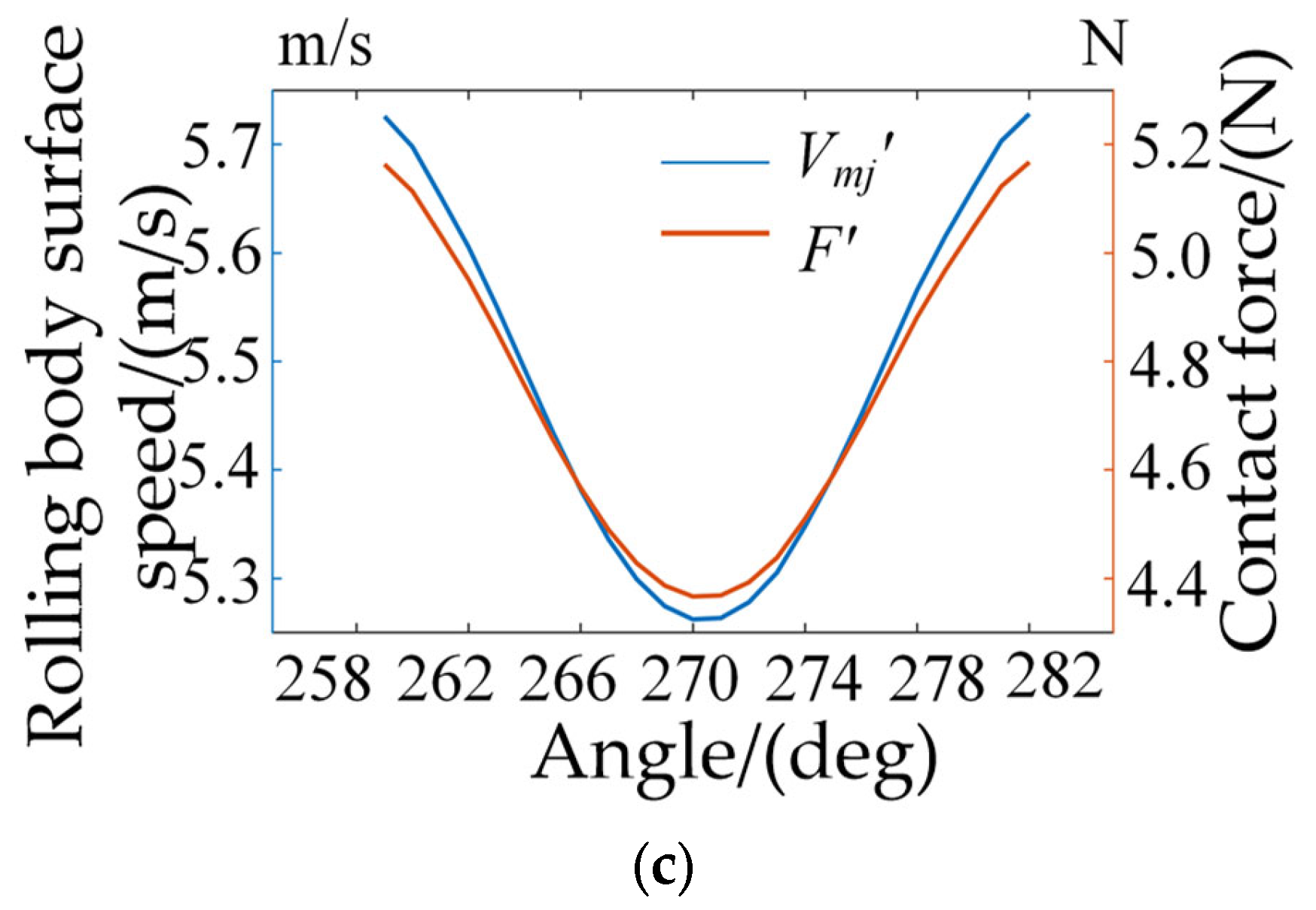
Figure 6, the horizontal coordinate in the figure corresponds to the angle between the rolling body and the x-axis, and 258° is the starting position of the functional slot in the outer ring of the bearing, whereas 282° is the end position.
As can be seen from Figure 6, with the rolling body moving in and out of the functional slot with different inner-ring speeds, the speed change trend is the same; the speed gradually decreases to the minimum value, and then the speed gradually increases until the rolling body is out of the functional slot. The rolling body does not contact with the inner ring after entering the functional slot, mainly due to the oil film friction and centrifugal force generated by the movement. The centrifugal force generated is mainly related to the speed of the rolling body; the greater the speed, the greater the centrifugal force generated. The corresponding contact force between the functional slot and the rolling body shows a trend of first becoming smaller and then larger. As shown in Figure 6a, when the inner ring speed is 1800 rpm, the speed of the rolling body is 5.7033 m/s when it enters the functional slot, and the speed is 5.248 m/s when the rolling body is located in the center of the functional slot. When the rolling body is out of the functional slot, even though the functional slot structure can make the speed of the rolling body gradually increase, the existence of oil film friction means that the speed of the rolling body cannot be restored to the speed when it enters the functional slot. When the speed of the inner ring is 3000 rpm and 6000 rpm, the speed of the rolling body in and out of the functional slot is the same. In order to analyze the change in the lubricant flow in the contact ellipse between the rolling body and the functional slot at the stage of the rolling body entering and leaving the functional slot, a position is selected at the stage of entering the functional slot, at the center of the functional slot, and at the stage of leaving the functional slot, respectively, for analysis.
The three positions of 260°, 270°, and 276° are selected, which correspond to position 1, position 2, and position 3, respectively, and will be described as position 1, position 2, and position 3 in the following section if there is no special case. Next, the oil film pressure and the oil film thickness between the rolling body and the functional slot are analyzed under three different inner-ring speeds, as shown in Figure 7.
When the radial loading Fr is 500 N, the oil film pressure and oil film thickness distribution between the rolling body and the functional slot under three different speed conditions are shown in Figure 7. It can be seen from the figure that the oil film pressure distribution between the rolling body and the functional slot has the same trend, and there are secondary peaks near the peak of the oil film pressure, while the oil film thickness decreases with the increase in the oil film pressure. As shown in Figure 7a, under the working condition of 1800 rpm, the peak oil film pressure is 0.534 × 10⁹ Pa, and the oil film thickness is 0.07 μm; the size of the secondary peak is 0.478 × 10⁹ Pa, and the corresponding oil film thickness is 0.27 μm. From Figure 7a,c,e, it can be seen that when the radial loading is the same, the change in oil film pressure is mainly caused by speed, and the larger the speed, the higher the oil film pressure peak is. The magnitude of the change in the secondary peak is more obvious; when the speed increases, the secondary peak pressure increases continuously, and when the inner ring speed is 6000 rpm, the secondary peak oil film pressure exceeds the original peak oil film pressure, which is caused by the large speed. When the secondary peak pressure is too large, it is very easy to lead to oil film breakage. From Figure 7b,d,f, it can be seen that the oil film thickness change trend is opposite to the oil film pressure change trend; when the oil film pressure increases, the oil film thickness decreases instead, and the downward hysteresis phenomenon appears at the secondary peak of pressure, with the minimum oil film thickness value increasing and decreasing with the speed of the working condition. Next, the results of the analysis of oil film pressure and oil film thickness at any point in the raceway with a reduced touch are shown in Figure 6.
Under different speed conditions, the distribution of oil film pressure and oil film thickness at any point between the rolling body and the functional slot is shown in Figure 8; the peak oil film pressure between the functional slot and the rolling body is reduced in value compared with the functional slot, but the pressure distribution range is increased. This also changes the oil film thickness distribution; in the contact area, the oil film thickness no longer remains the same but undergoes a process of decreasing and then contraction.
From Figure 8a–c, it can be seen that when the rolling body enters into the functional slot, the contact force between the rolling body and the raceway decreases rapidly, and the contact force between the rolling body and the raceway at this time mainly comes from the centrifugal force of the rolling body; thus, the larger the speed of the inner ring, the larger the pressure peak. It can be seen from the figure that when the speed is 1800 rpm, the peak pressure of the oil film is 0.724 × 10⁷ Pa, and the thickness of the oil film is 1.48 μm; when the speed is increased to 6000 rpm, the peak pressure of the oil film is 1.06×10⁷ Pa, and the thickness of the oil film is 0.61 μm. From the above analysis, it can be seen that the contact force between the rolling body and the raceway after the rolling body enters into the functional slot mainly comes from the centrifugal force of the rolling body, and the centrifugal force of the rolling body is mainly related to the speed of the rolling body. Thus, the oil film pressure between the rolling body the functional slot and the oil film thickness distribution in the functional slot are mainly related to the speed of the rolling body; the larger the inner ring speed, the larger the peak oil film pressure and the smaller the oil film thickness. The contact ellipse ratio increases, resulting in a secondary peak in the oil film pressure, and the pressure distribution gradually decreases and finally disappears, while the pressure peak gradually returns to the center of the contact area with an increase in rotational speed. Combined with the results about the elastic deformation of the rolling body and the surface of the raceway, it can be seen that compared with the functional slot, the contact ellipse ratio between the rolling body and the raceway increases, so the secondary peak of the oil film pressure between the rolling body and the raceway disappears, which corresponds to the conclusion of the numerical solution. Next, the oil film pressure and oil film thickness at the three positions in the functional slot are analyzed, and the results are shown in Figure 9.
The oil film pressure and film thickness of the rolling body at the three positions of Z = 0 in the raceway are analyzed at different rotational speeds. As shown in Figure 9a, under the same working conditions, the trends of the oil film pressure and oil film thickness distribution at the three positions in the raceway are more or less the same. The oil film thickness decreases with an increase in the oil film pressure value, and the oil film thickness decreases suddenly when the secondary peak of the oil film pressure disappears, with the oil film thickness also showing a decreasing trend in the contact area. When the speed is increased to 3000 rpm, it can be seen from Figure 9c that the difference between the peak oil film pressure at the three positions is smaller, and the peak pressure point gradually returns to the center of the contact area; at this time, although the oil film thickness in the contact area has been in a decreasing stage, the decrease is obviously less than 1800 rpm.
When the inner ring speed is increased to 6000 rpm, it can be seen from Figure 9e that the peak oil film pressure at the three positions has almost no deviation, and the peak pressure point returns to the center of the contact area; at this time, the oil film thickness in the contact area does not change, but the hysteresis phenomenon occurs. According to the above analysis, it can be seen that the oil film pressure and the oil film distribution between the rolling body and the raceway with reduced touching are generally not much different when the rolling body is passing through the raceway, and the speed of the rolling body is the main factor causing the difference. Next, an analysis of the oil film flow rate between the rolling body and the functional slot is performed, and the results are shown in Figure 10.
According to the distribution law of the oil film pressure and the oil film thickness between the rolling body and the raceway, the oil film flow velocity curve in the elliptical contact area between the rolling body and the raceway can be obtained, as shown in Figure 8, when the oil film velocity is at Z = 0, and Y = 0.5.
When the rolling body is moving inside the functional slot, its surface lubricant flow speed increases gradually from the entrance area; when combined with Figure 9, it can be seen that the oil film pressure value at the entrance area increases gradually from zero. When the oil film pressure value is zero, the oil film does not flow; when it reaches the contact ellipse area between the rolling body and the functional slot, its internal oil film flow speed is similar to the roll absorption speed between the rolling body and the functional slot; and when it reaches an abrupt change in the oil film thickness, the oil film speed also changes abruptly and then gradually decreases to the roll absorption speed. The oil film velocity also changes abruptly when it reaches a sudden change in the oil film thickness and then gradually decreases to the roll suction velocity, according to the above analysis. Under the condition that the inner ring speed is 1800 rpm, as shown in Figure 10a, the oil film flow velocity increases at the entrance area to the same as the roll suction velocity; however, in the contact ellipse area, when combined with Figure 9a, it can be seen that the oil film thickness in the contact area has been constantly decreasing, so it leads to the oil film velocity in the contact area. The oil film velocity in the contact area increases continuously, but the growth trend is very small, and then no longer increases; afterward, the oil film velocity increases suddenly at the point where the oil film shrinks. As shown in Figure 10b, when the inner ring speed is 3000 rpm, the oil film velocity changes roughly the same law. When the inner ring speed is 6000 rpm, as shown in Figure 10c, the oil film flow velocity increases at the entrance area to the same as the winding velocity; the oil film velocity at the entrance contact area is different from the other two working conditions; and the oil film velocity does not change at this stage until the point where the oil film thickness undergoes a sudden increase. It can be seen from the graph that the value of the oil film velocity surge is related to the rolling body velocity; the larger the rolling body velocity, the larger the oil film flow velocity and the velocity after the surge.
Based on the above analysis of the three working conditions with the inner ring speed at 1800 rpm, 3000 rpm, and 6000 rpm, for a ball bearing without cage and containing raceway with reduced touching, the lubricant film characteristics of the rolling body moving in and out of the raceway can be concluded as follows:
Due to the existence of the functional slot, the oil film pressure distribution and the film thickness distribution shape formed by the rolling body and the functional slot are changed. When the rolling body is passing through the functional slot, the speed of roll absorption and the size of contact force between the rolling body and the functional slot mainly depend on the inner-ring rotational speed; the larger the inner-ring rotational speed, the larger the roll absorption speed and the contact force between the rolling body and the functional slot. In the contact ellipse between the rolling body and the functional slot, the oil film flow speed is mainly related to the roll absorption speed between the rolling body and the functional slot; the larger the roll absorption speed, the larger the oil film flow; and the oil film pressure and the oil film thickness have a significant impact on the contact ellipse. In the contact ellipse of the rolling body and the contact roller, the flow speed of the oil film is mainly related to the roll suction speed between the rolling body and the contact roller; the larger the roll suction speed, the larger the oil film flow. The oil film pressure and the oil film thickness have an influence on the flow speed of the oil film in the contact ellipse, but compared with the two factors, the oil film thickness has a greater influence. Through the above analysis, it can be seen that at the point where the oil film thickness changes abruptly, the flow rate of the oil film of the rolling body and the reduced-touching raceway is also abruptly changed accordingly.

4. Analysis of the Overall Lubrication State of the Ball Bearing without Cage

4.1. Analysis of the Oil Required between Rolling Body and Raceway

For ball bearing operation without cage and containing a functional slot, the lubricating oil quantity in the rolling body, the conventional raceway, and the functional slot contact ellipse cannot form a complete oil film, which will lead to poor oil lubrication. When the contact area’s lubricating oil quantity can form a complete oil film, poor oil lubrication phenomenon will not occur. The mass moil of lubricating oil required in the contact area of each rolling body and oiled raceway ellipse is calculated as follows:
m o i l = u 1 ρ h 0
where u1’ is the rolling body surface speed, in m/s, and h0 is the central oil film thickness, in mm.
During the operation of the ball bearing with a functional slot and no cage, in order to prevent the bearing from running out of oil, it is necessary to ensure that the amount of lubricating oil between the rolling element and the contact area of the raceway is greater than the required amount of oil. Considering the numerical solution under the working conditions of different speeds, the required amount of oil for the ball bearing with a functional slot and no cage is shown in Figure 11.
From Figure 11, it can be seen that under different speed conditions, the amount of lubricating oil required for the ball bearing containing a functional slot without cage increases with an increase in the inner-ring speed. Under the premise that the annular span angle, as well as the axial span angle, is determined, the initial oil quantity of the ball bearing containing a functional slot without cage is only related to the depth of the functional slot, and it can be seen that the greater the depth of the functional slot, the greater the initial oil quantity. Under different speed conditions, the relationship between the initial amount of oil required by the rolling element and the depth of the functional slot is shown in Figure 12.
Under different speed conditions, the required lubricant oil quantity is different; the higher the speed of the inner ring, the more the required initial lubricant oil quantity, so the depth of the functional slot is also bigger. However, due to the structural parameters of the bearing itself, the depth of the functional slot cannot exceed the difference between the radius of the outer ring of the bearing and the radius of the bottom of the slot of the outer ring; thus, the depth of the functional slot cannot exceed 3.235 mm, otherwise it will destroy the bearing structure. Therefore, combining the results of Figure 11 and Figure 12, it is necessary to ensure that the inner-ring speed cannot exceed 4200 rpm in order to ensure good lubrication of the bearing in the initial running condition; when the inner-ring speed of the ball bearing with a functional slot without cage exceeds a 4200 rpm working condition, additional lubrication treatment is required for the ball bearing with a functional slot without cage.

4.2. Analysis of Oil Film Thickness between Rolling Body and Raceway

Under good lubrication condition, the contact surface between each rolling element and the conventional raceway, as well as the functional slot of the ball bearing, should be separated by a lubricant, at which time an oil film is formed under the action of the contact force between the rolling element and the raceway as well as the rolling element speed. After the bearing operation is stabilized, the oil film thickness between each rolling element and the conventional raceway and functional slot is analyzed by selecting a position, as shown in Figure 13.
The position of the rolling element in the raceway of the ball bearing with a functional slot and without cage is selected as shown in Figure 13, at this time the rolling element is evenly distributed in the raceway, and the position of each rolling element is shown in the figure. Then, the oil film thickness between each rolling element and the conventional raceway, and between each rolling element and the functional slot, is analyzed, and the results are shown in Figure 14.
As shown in Figure 14, under the working conditions of different speeds, the oil film thickness between the rolling body and the conventional raceway and the functional slot shows regular changes; in general, the oil film thickness between the rolling body and the conventional raceway located in the non-load-bearing area is greater than that between the rolling body and the conventional raceway in the load-bearing area, and the oil film thickness between the rolling body and the functional slot located in the functional slot is similar to that of the non-load-bearing area in value.
The above results are mainly due to the fact that the rolling bodies numbered 1 to 7 are located in the non-load-bearing area of the conventional raceway because, at this time, the rolling bodies do not bear a radial load, and mainly the centrifugal force plays a leading role. Considering the existence of friction when the rolling bodies are in contact with the conventional raceway, the speed of the rolling bodies numbered 1 to 7 is gradually reduced, which makes the centrifugal force generated by the movement of the rolling bodies gradually reduce, according to Section 3.2. According to the content analysis, the smaller the contact force between a rolling body and the conventional raceway, the smaller the oil film pressure between them and the larger the oil film thickness; thus, the oil film thickness has a gradually increasing trend. The contact force between rolling body 8, rolling body 9, rolling body 10, and the conventional raceway located in the bearing area, under the action of radial load, gradually increases, and so the oil film thickness gradually decreases; the oil film thickness between rolling body 11 and the functional slot located in the functional slot has been described, and it should be noted that the value is similar to the oil film thickness in the non-bearing area, which is mainly due to the fact that when the rolling body is located in the above position, it is dominated by centrifugal force. The contact force between rolling body 12, rolling body 13, rolling body 14, and the conventional raceway located on the conventional raceway in the out-load zone gradually decreases, and the oil film thickness has a tendency to gradually increase.

5. Lubricant Flow Observation Test for Ball Bearing without Cage and Containing Functional Slot

In order to observe the flow effect of lubricant at different rotational speeds when the rolling element is out of the functional slot, the ball bearing containing a functional slot without cage is mounted on a T10-60 model bearing testing machine, and the lubricant flow status is recorded using a high-speed photography device. Figure 15 shows the physical diagram of the lubricant observation test bench. The lubricant observation device includes two parts: the bearing testing machine and the high-speed photography device. The bearing test machine includes a bearing operation test bench and a control platform, in which the observed test bearing, the load bearing, and the support bearing are installed on the spindle in the order of the figure (in which the load bearing and the support bearing both adopt 6206 deep-groove ball bearing), the spindle is connected with an electric spindle through a flexible coupling; the movement of the electric spindle drives the rotation of the spindle; and the control platform can control the speed of the electric spindle and the radial loading value. The high-speed photography device includes a light source, a high-speed camera, and a storage device; the light source and the high-speed camera are aimed at the bearing to be observed; and the lubricant distribution status is recorded after the bearing is running.
In order to verify that the initial amount of oil in the functional slot of a ball bearing containing a functional slot without cage can generate a good lubricating effect, the inner and outer rings of the bearing are weighed and measured using a BSM electronic balance after the test, and a larger weighing result indicates that the bearing wear is smaller, as shown in Figure 16.
In this paper, the lubricating oil observation and analysis are carried out for ball bearings with a functional slot depth of 2.5 mm and without cage under the conditions of 1800 rpm, 3000 rpm, and 6000 rpm; the initial volume of the lubricating oil is added to the internal volume of the functional slot without additional lubricating treatment, and the flow of the lubricating oil when the rolling element comes out of the raceway of the functional slot under different speed conditions is studied. The results of the high-speed photography are analyzed and shown in Figure 17a. Because the material of the bearing testing machine is steel, when the light source is irradiated, it produces visual reflection points, which are not conducive to the analysis of lubricant flow in the bearing raceway; thus, the high-speed photographic pictures are grayed out as shown in Figure 17b. After the high-speed photographic pictures are grayed out, the visual reflection points and blind spots are reduced, and it is easier to analyze the lubricant flow results. The next step is to verify the results of the experiment, as shown in Figure 18.
As shown in Figure 18, under the same working condition of an inner-ring speed of 1800 rpm and a radial loading of 500 N, the surface lubricant is thrown on the raceway after the rolling body passes through the functional slot. Next, the lubricating effect of the surface lubricant thrown on a latter rolling body when the rolling body is out of the functional slot under the speed of 3000 rpm is analyzed, and the results are shown in Figure 19.
Figure 19 shows the analysis of the amount of lubricant on the surface when rolling body 1 comes out of the functional slot. At t1 moment, rolling body 1 is located at the center of the functional slot; at this time, the lubricant dumped by the surface of the previous rolling body exists in the lubrication chamber between rolling body 1 and the previous rolling body. At t2 moment, rolling body 1 comes out of the functional slot, and at this time, the lubricant has not yet fallen on the surface of rolling body 1 and the conventional raceway. At t3 moment, the lubricant has fallen on the raceway surface, which will provide base oil quantity for the oil film formed between rolling body 1 and the conventional raceway. At t4 moment, the latter rolling body reaches the center of the functional slot, and at this time, rolling body 1 throws excess lubricating oil on the surface of the lubricating cavity through its rotation movement, which will provide base oil quantity for the oil film formed between the latter rolling body and the conventional raceway. This process is repeated through the cyclic rotation movement of the rolling bodies, finally realizing a lubricating oil-containing functional slot in the slot without cage ball bearing lubrication. The results of the next analysis of the surface lubricant volume of the rolling element when it is out of the functional slot under different speed conditions are shown in Figure 20.
As shown in Figure 20, when the depth of the functional slot is 2.5 mm, the volume of lubricating oil added before the bearing operation is 91.78 mm3, and the volume of lubricating oil at this time meets the requirements of bearing lubrication under 1800 rpm and 3000 rpm operating conditions, which can be seen in Figure 20a,b. The amount of lubricating oil carried by the functional slot after the bearing runs steadily is obviously larger than the amount of lubricating oil thrown out from the surface of the rolling body under the condition of 6000 rpm (Figure 20c).
When lubrication is sufficient, the lubricant can reduce the friction between the rolling element and the raceway, so that the bearing operation is more stable. When the depth of the functional slot is 2.5 mm, the vibration curve of the ball bearing with a functional slot and no cage is shown in Figure 21. When the speed of the inner ring of the bearing is 1800 rpm and 3000 rpm, according to the above analysis, it is known that the bearing lubrication is sufficient, and the vibration acceleration value is not much different, but the vibration value increases due to an increase in speed. When the speed of the inner ring of the bearing is 6000 rpm, the vibration acceleration value increases obviously. On the one hand, because of the increase in bearing running speed, the functional slot with a 2.5 mm depth is not enough to form a good lubrication state when the inner ring speed is 6000 rpm. As shown in the figure, when the inner-ring speed is 3000 rpm, under the condition of not adding lubricating oil, the vibration acceleration value of the ball bearing motion increases significantly. The bearing testing machine was then disassembled, the inner and outer rings were cleaned using an ultrasonic cleaning instrument; and the inner- and outer-ring raceways of the ball bearing with functional slot and without cage were weighed and analyzed using a BSM electronic balance.
The results after weighing the inner- and outer-ring raceways of the ball bearing with functional slot and without cage using a BSM electronic balance are shown in Figure 22. Figure 22a shows the initial weight of the outer ring and the inner ring with a functional slot of 2.5 mm in depth; Figure 22b shows the mass of the inner and outer rings after 30 h of continuous operation at a speed of 1800 rpm; Figure 22c shows the mass of the inner and outer rings after 30 h of continuous operation at a speed of 3000 rpm; Figure 22d shows the mass of the inner and outer rings after 30 h of continuous operation at a speed of 6000 rpm; Figure 22e shows the mass of the inner ring after 30 h of continuous operation at a speed of 3000 rpm without adding lubricant. From the figure, it can be seen that under the same initial oil volume, the difference between the mass of the inner and outer rings of the bearing after the test under the conditions of 1800 rpm and 3000 rpm is not large; this is because the initial oil volume in the functional slot can meet the required oil volume for lubrication. The wear volume under the condition of 6000 rpm is obviously larger, and this is because when the initial oil volume is the volume of the functional slot, the lubricant in the functional slot with a depth of 2.5 mm is not sufficient for lubrication. Although it can reduce part of the friction and vibration, the lubrication effect is greatly reduced compared to the other two conditions. In the bearing with an inner-ring speed of 3000 rpm and without any lubricant, it can be seen that the wear amount is greater and the vibration value also increases. This corresponds with the results of the high-speed photographic test and the vibration test.

6. Conclusions

The initial oil quantity equation of a ball bearing without cage and containing a functional slot is established by analyzing the structure of the functional slot, and then a lubricating oil flow model and an elastohydrodynamic lubrication equation system of the ball bearing without cage and containing a functional slot are established. The relationship between the oil film pressure and oil film thickness at the functional slot and the oil film characteristics of the rolling element at the functional slot are mainly related to the speed of the bearing, as obtained from the numerical solution. By analyzing the amount of lubricating oil required for bearing lubrication, the range of functional slot depth under different speed conditions is determined. Finally, the distribution of oil film thickness between the rolling element and the raceway under sufficient lubrication conditions is obtained. According to the high-speed photographic test, the vibration test, and the wear test, it is concluded that the lubricating oil in the functional slot can have an effect on lubrication, and the depth of the functional slot determines the lubrication effect of the bearing when the initial oil volume is the volume of the functional slot.

7. Discussion

The limitations of this study include the following:
1. The set of elastohydrodynamic lubrication equations established in this paper does not take into account the effect of internal forces of the lubricant, such as inertia forces and centrifugal forces of the oil film, which need to be studied in the future.
2. This paper does not consider the effect of lubricant temperature rise on oil film characteristics, which needs to be studied.
3. This paper considers that a reasonable depth of the raceway can ensure a good lubrication condition of the bearing, but the influence of the change in residual stress after the processing of the raceway in the outer ring of the bearing is not considered, which needs to be researched.

Author Contributions

Conceptualization, Y.Z. (Yuan Zhang); Software, W.H.; Investigation, Y.Z. (Yanling Zhao); Writing—original draft, J.Z. All authors have read and agreed to the published version of the manuscript.

Funding

This work was financially supported by the National Natural Science Foundation of China (51375125).

Data Availability Statement

No new data were created or analyzed in this study. Data sharing is not applicable to this article.

Conflicts of Interest

The authors declare no conflict of interest.

References

  1. Jia, Q.; He, W.; Hua, D.; Zhou, Q.; Du, Y.; Ren, Y.; Lu, Z.; Wang, H.; Zhou, F.; Wang, J. Effects of structure relaxation and surface oxidation on nanoscopic wear behaviors of metallic glass. Acta Mater. 2022, 232, 117934. [Google Scholar] [CrossRef]
  2. Wang, W.; Hua, D.; Zhou, Q.; Li, L.; Eder, S.J.; Shi, J.; Wang, Z.; Wang, H.; Liu, W. Effect of a water film on the material removal behavior of Invar during chemical mechanical polishing. Appl. Surf. Sci. 2023, 616, 156490. [Google Scholar] [CrossRef]
  3. Ye, W.; Xie, M.; Huang, Z.; Wang, H.; Zhou, Q.; Wang, L.; Chen, B.; Wang, H.; Liu, W. Microstructure and tribological properties of in-situ carbide/CoCrFeNiMn high entropy alloy composites synthesized by flake powder metallurgy. Tribol. Int. 2023, 181, 108295. [Google Scholar] [CrossRef]
  4. Hamrock, B.J.; Dowson, D. Isothermal Elastohydrodynamic Lubrication of Point Contacts: Part III—Fully Flooded Results. J. Lubr. Technol. 1977, 99, 264–275. [Google Scholar] [CrossRef]
  5. Hamrock, B.J.; Dowson, D. Isothermal Elastohydrodynamic Lubrication of Point Contacts: Part I—Theoretical Formulation. J. Lubr. Technol. 1977, 98, 223–228. [Google Scholar] [CrossRef]
  6. Hamrock, B.J.; Dowson, D. Isothermal Elastohydrodynamic Lubrication of Point Contacts: Part II—Ellipticity parameter Results. J. Lubr. Technol. 1976, 98, 375–381. [Google Scholar] [CrossRef]
  7. Yang, S. New developments in elastohydrodynamic theory and its application to rolling bearings. Bearings 1985, 4, 54–59+66. [Google Scholar]
  8. Liu, Y.; Wang, W.; Qing, T.; Zhang, Y.; Liang, H.; Zhang, S. The Effect of Lubricant Temperature on Dynamic Behavior in Angular Contact Ball Bearings. Mech. Mach. Theory 2019, 149, 103832. [Google Scholar] [CrossRef]
  9. Guo, K.; Yuan, S.H.; Zhang, Y.Y. Study on the calculation of mechanical properties of ball bearings with elastohydrodynamic lubrication considering spin state. J. Mech. Eng. 2013, 49, 62–67. [Google Scholar] [CrossRef]
  10. Lei, C.; Li, F.; Guo, J.; Yang, X. Analysis of rolling bearing oil film stiffness based on multi-parameter coupling. Vib. Shock. 2018, 37, 225–232. [Google Scholar]
  11. Xing, H.; Chang, L.; Yan, Z. Numerical calculation and analysis of influencing factors for elliptical point contact elastohydrodynamic lubrication. Mach. Des. 2018, 35, 58–64. [Google Scholar]
  12. Wang, Y.; Yan, K.; Zhu, Y.; Hong, J.; Zhang, Y.Y. Analysis of gas phase flow in the cavity of angular contact ball bearings under different guidance of cage. J. Mech. Eng. 2017, 53, 72–78. [Google Scholar] [CrossRef]
  13. Ge, L.; Chen, F.; Yan, K. Research on lubrication efficiency of high-speed bearings for oil-depleted conditions. J. Mech. Eng. 2022, 58, 154–161. [Google Scholar]
  14. Donglei, Z.; Guoding, C.; Yanjun, L. Analysis of slip oil flow and lubrication efficiency in the lower runner of intermediate bearing ring. J. Aeronaut. 2019, 40, 309–323. [Google Scholar]
  15. Yanni, L.; Hua, S.; Guoding, C. Analysis of the influence of oil inlet structure type on bearing lubrication performance. Lubr. Seal. 2005, 1, 82–83. [Google Scholar]
  16. Zhang, Z.; Zhang, Y.H.; Chen, G.D.; Song, L.M. Flow field analysis of intermediate bearing lubrication system in aero engines. Bearing 2004, 12, 22–24. [Google Scholar]
  17. Zhang, Y.H.; Song, L.M.; Chen, G.D.; Zhang, Z.H. New structure research based on intermediate bearing lubrication performance improvement. Lubr. Seals 2005, 3, 124–125. [Google Scholar]
  18. Zhang, Y.H.; Chen, G.D.; Song, L.M. Analysis of the influence of the structural parameters of the combined fan/ring lower bore on the lubrication performance of bearings. Mech. Transm. 2005, 29, 55–57. [Google Scholar]
  19. Liu, M.; Guo, F.; Jiao, Y.; Guo, S.L.; Wang, X. A new infusion type oil-air lubrication nozzle. China Mech. Eng. 2018, 29, 1284–1288. [Google Scholar]
  20. Akamatsu, Y.; Mori, M. Minimizing Lubricant Supply in an Air-Oil Lubrication System. NTN Tech. Rev. 2004, 71, 12–19. [Google Scholar]
  21. Jiang, S.; Mao, H. Investigation of the High SpeedRolling Bearing Temperature Rise with Oil-air Lubrication. J. Tribol. 2011, 133, 655–664. [Google Scholar] [CrossRef]
  22. Zhang, Y. CAE Analysis of Gas-Liquid Lubrication Nozzle; Wuhan University of Technology: Wuhan, China, 2007; pp. 48–52. [Google Scholar]
  23. Kosugi, F. Rolling Bearing and Rolling Bearing Assembly. U.S. Patent 20130202237A1, 7 February 2013. Available online: https://patents.google.com/patent/US20130202237A1/en.html (accessed on 14 February 2015).
  24. Yan, K.; Dong, L.; Zheng, J.; Li, B.; Wang, D.; Sun, Y. Flow Performance Analysis of Different Air Supply Methods for High Speed and Low Friction Ball Bearing. Tribol. Int. 2018, 121, 94–107. [Google Scholar] [CrossRef]
  25. Yan, Z.; Li, Y.; Yuan, H.; Mei, N. Numerical study of droplet impact on a micro-scale rectangular trench surface. J. Eng. Thermophys. 2018, 39, 1542–1548. [Google Scholar]
Figure 1. Principle diagram of lubricant flow of ball bearing without cage and containing functional slot.
Lubricants 11 00203 g001
Figure 2. Schematic diagram of rolling body over a functional slot. (a) Schematic diagram of a single ball over the functional slot. (b) Maximum displacement diagram of a rolling body.
Lubricants 11 00203 g002
Figure 3. Internal volume of the functional slot.
Lubricants 11 00203 g003
Figure 4. Contact equivalent radius diagram of rolling element on the functional slot.
Lubricants 11 00203 g004
Figure 5. Calculation flow chart.
Lubricants 11 00203 g005
Figure 6. Rolling body speed and indirect contact force with the functional slot at different speeds: (a) contact force between rolling body speed and raceway at 1800 rpm; (b) contact force between rolling body speed and raceway at 3000 rpm; and (c) contact force between rolling body speed and raceway at 6000 rpm.
Lubricants 11 00203 g006aLubricants 11 00203 g006b
Figure 7. Oil film pressure and thickness distribution between the rolling element and conventional raceway at different speeds: (a) 1800 rpm of oil film pressure; (b) 1800 rpm of oil film thickness; (c) 3000 rpm of oil film pressure; (d) 3000 rpm of oil film thickness; (e) 6000 rpm of oil film pressure; and (f) 6000 rpm of oil film thickness.
Lubricants 11 00203 g007
Figure 8. Oil film pressure and thickness distribution between the rolling element and the functional slot at different speeds: (a) 1800 rpm of oil film pressure; (b) 1800 rpm of oil film thickness; (c) 3000 rpm of oil film pressure; (d) 3000 rpm of oil film thickness; (e) 6000 rpm of oil film pressure; and (f) 6000 rpm of oil film thickness.
Lubricants 11 00203 g008aLubricants 11 00203 g008b
Figure 9. Oil film pressure and thickness distribution at three positions of functional slot at different speeds: (a) oil film pressure distribution at Z = 0 in the functional slot at 1800 rpm(X); (b) oil film thickness distribution at Z = 0 in the functional slot at 1800 rpm(X); (c) oil film pressure distribution at Z = 0 in the functional slot at 3000 rpm(X); (d) oil film thickness distribution at Z = 0 in the functional slot at 3000 rpm(X); (e) oil film pressure distribution at Z = 0 in the functional slot at 6000 rpm(X); and (f) oil film thickness distribution at Z = 0 in the functional slot at 6000 rpm(X).
Lubricants 11 00203 g009
Figure 10. Oil film flow velocity between the rolling element and the functional slot at different speeds: (a) oil film pressure distribution at Z = 0 in the functional slot at 1800 rpm(X); (b) oil film pressure distribution at Z = 0 in the functional slot at 3000 rpm(X); and (c) oil film pressure distribution at Z = 0 in the functional slot at 6000 rpm (X).
Lubricants 11 00203 g010
Figure 11. The amount of lubricating oil required for different speeds.
Lubricants 11 00203 g011
Figure 12. Relationship between functional slot depth and initial oil volume.
Lubricants 11 00203 g012
Figure 13. The rolling body distribution of ball bearing with a functional slot without cage.
Lubricants 11 00203 g013
Figure 14. Oil film distribution between the rolling body and raceway.
Lubricants 11 00203 g014
Figure 15. Lubricant observation test bench.
Lubricants 11 00203 g015
Figure 16. BSM electronic balance.
Lubricants 11 00203 g016
Figure 17. High-speed photographic grayscale processing results: (a) before processing, and (b) after processing.
Lubricants 11 00203 g017
Figure 18. The results of the functional slots at different locations.
Lubricants 11 00203 g018
Figure 19. Lubricant distribution evolution process: (a) moment t1; (b) moment t2; (c) moment t3; and (d) moment t4.
Lubricants 11 00203 g019aLubricants 11 00203 g019b
Figure 20. Lubricant distribution at different speeds: (a) at 1800 rpm; (b) at 3000 rpm; and (c) at 6000 rpm.
Lubricants 11 00203 g020aLubricants 11 00203 g020b
Figure 21. Bearing vibration data at different speeds.
Lubricants 11 00203 g021
Figure 22. Bearing wear under different working conditions: (a) initial weight of inner and outer raceways; (b) weight of inner and outer raceways at 1800 rpm; (c) weight of inner and outer raceways at 3000 rpm; (d) weight of inner and outer raceways at 6000 rpm; and (e) weight of inner and outer raceways at 3000 rpm without lubrication.
Lubricants 11 00203 g022aLubricants 11 00203 g022b
Table 1. Parameters of ball bearings without cage and with functional slot.
ParametersDimensionless Posterior Parameter Representation
Oil film x-direction flow velocity uU = u/ue
Oil film y-direction flow velocity vV = v/ue
Oil film z-direction flow speed wW = w/ue
Rolling body surface velocity u1U1= u1/ue
Rolling body surface velocity v1V1= v1/ue
Rolling body surface speed w1W1= w1/ue
Lubricant x-direction flow MxMx = mx/a
Lubricant z-direction flow rate MzMz = mz/b
Coordinates xX = x/a
Coordinates yY = y/h
Coordinates zZ = z/b
Oil film thickness hH = h/a
Oil film pressure pP = p/ph
Lubricant viscosity η η ¯ = η / η 0
Long semi-axis of the contact area between the rolling body and the raceway a a = 1.1447 e a E * ( F ρ ) 1 3
Short semi-axis in the contact area between the rolling body and the raceway b b = 1.1447 e b E * ( F ρ ) 1 3
Table 2. Lubrication calculation parameters for ball bearings without cage and containing a functional slot.
ParametersNumerical Value
Rolling body modulus of elasticity E1207 GPa
Modulus of elasticity of outer ring E2207 GPa
Rolling body Poisson’s ratio υ10.29
Poisson’s ratio of outer ring υ20.29
Lubricant initial densityρ0992 kg/m3
Initial viscosity of the lubricant η00.050 Pa·s
Lubricant viscosity pressure coefficient α1.85 × 10⁻⁸ m2/N
Circumferential span angle θx24°
Axial span angle θz42.8°
Disclaimer/Publisher’s Note: The statements, opinions and data contained in all publications are solely those of the individual author(s) and contributor(s) and not of MDPI and/or the editor(s). MDPI and/or the editor(s) disclaim responsibility for any injury to people or property resulting from any ideas, methods, instructions or products referred to in the content.

