Article

Effect of Chamfer Form and Parameters on the Characteristics of Finite Length Journal Bearing under Impact Load

by
Hazim U. Jamali
1,
Hakim S. Sultan
2,
Oday I. Abdullah
3,4,5,*,
Adnan Naji Jameel Al-Tamimi
6,
Luay Hashem Abbud
7,
Alessandro Ruggiero
8 and
Zahraa A. Al-Dujaili
1
1
Mechanical Engineering Department, College of Engineering, University of Kerbala, Karbala 56001, Iraq
2
College of Engineering Karbala, University of Warith Al-Anbiyaa, Karbala 56001, Iraq
3
Department of Energy Engineering, College of Engineering, University of Baghdad, Baghdad 17635, Iraq
4
Institute of Laser and Systems Technologies (iLAS), Hamburg University of Technology (TUHH), Harburger Schloßstraße 28, 21079 Hamburg, Germany
5
Mechanical Engineering Department, College of Engineering, Gulf University, Sanad 26489, Bahrain
6
College of Technical Engineering, Al-Farahidi University, Baghdad 10022, Iraq
7
Air conditioning and Refrigeration Techniques Engineering Department, Al-Mustaqbal University College, Hillah 51001, Iraq
8
Department of Industrial Engineering, University of Salerno, 84084 Fisciano, Italy
*
Author to whom correspondence should be addressed.
Lubricants 2023, 11(2), 73; https://doi.org/10.3390/lubricants11020073
Submission received: 9 January 2023 / Revised: 6 February 2023 / Accepted: 8 February 2023 / Published: 10 February 2023
(This article belongs to the Special Issue Tribology Problems in Rotating Machinery)

Abstract

:
Journal bearings in typical applications are subjected to misalignment due to several causes, such as shaft deformation under load and errors related to the installation and manufacturing processes. Misalignment has well-known severe negative consequences on the performance of the bearings. This paper deals with the bearing chamfer to reduce these consequences of misalignment, and two forms of bearing edge modification are considered in the analysis. These forms are linear and curved chamfering of the bearing edges, where the height of the chamfer in the circumferential direction and the length of the modification in the longitudinal direction are considered as geometrical design parameters. The investigation includes a numerical solution of the hydrodynamic lubrication problem of finite length journal bearing, considering 3D misalignment cases using the finite difference method. This includes the assessment of the chamfer forms and their effects on the bearing performance in terms of the main bearing design parameters. Furthermore, the stability of the chamfered bearings is also investigated under impact load. Results showed that both chamfer forms are beneficial for a certain limit of the design parameters in reducing the maximum pressure and coefficient of friction and in elevating the film thickness levels, extending the range of misalignment in which the journal bearing can operate safely. In addition, the chamfered bearings in both forms showed more stability range in terms of the critical speed and shaft center trajectories under impact load. The bearings with the curved chamfer, where the slope is continuous at the start of modification, showed more uniform film thickness levels, and their shaft center trajectories were closer to the perfectly aligned bearing in the stable operating range of the system.

Graphical Abstract

1. Introduction

Oil film journal bearings have been widely used in rotating machinery operating at high speed, such as compressors and turbines, for the extra damping they provide, their superior durability, and the relatively low cost of maintenance [1]. Therefore, this type of bearing is considered one of the most important machine elements for enhancing the rotating machinery’s operation quality [2]. However, dynamic instabilities are intrinsic characteristics of these bearings [3]. The problem of hydrodynamic lubrication of journal bearing has been extensively studied over the last decades. One of the most significant studies in the field of dynamic characteristics of fluid film bearings was performed by Lund and Thomsen [4]. In their study, they presented an extensive analysis to calculate numerically the fluid film damping and stiffness coefficients that are used to understand the effects of these coefficients on the rotor dynamic stability. However, the misalignment effect was not considered in their study. Chang and Zheng [5] used an experimental method for the estimation of the dynamic coefficients of journal bearing used in high-speed rotational machines. Their results emphasized the importance of accuracy in determining the dynamic coefficients in such applications of the journal bearing. The dynamic coefficients of a rotor bearing system were also determined by Subbiah et al. [6], and they pointed out the difficulties related to the determination of these coefficients when the system works at high eccentricity ratios. The inaccuracies in the determination of the dynamic characteristics were studied by Klit and Lund [7], where they used an alternative method of a linear perturbation in solving the Reynolds equation.
The importance of the dynamic characteristics of the bearing system in predicting the noise and vibration levels of the engine was examined by Nefske and Sung [8]. They investigated an internal combustion engine’s combustion excitation as it is transferred from the crankshaft to the engine block through the bearing fluid film. The experimental measurements of the dynamic coefficients and their related inaccuracies were investigated by Lund [9] and by Kostrzewsky and Flack [10]. The reported discrepancies with corresponding numerical results were attributed to the nature of coefficient measurements as they cannot be measured directly. The coefficients are derived, in fact, from the results of other measurements, which are, on the other hand, related to the test conditions. The modern applications of the rotating machineries need to be consistent with the high-power demand that increases the speed of these machineries. On the other hand, the high levels of speed increase the instability problems related to the rotor bearing system. Journal bearing is subjected under high speed to oil whirl and whip, which are well-known problems related to dynamic instability [11]. In such cases, the shaft vibrates at a constant frequency, displacing the shaft from the equilibrium position [12]. As a result of this and due to unbalance forces, the shaft starts whirling in a relatively thin clearance between the shaft and the bearing, which may result in instability of the journal bearing system.
The perfect situation of the aligned journal bearing rarely exists as in this ideal case it is supposed that the journal axis remains parallel to the bearing axis despite the large supported load under high rotational speed. In the typical uses of this type of bearing, the journal will be exposed to some extent to a level of misalignment due to the shaft deformation, errors related to manufacturing and installation of the bearing system, bearing wear, load asymmetricity, etc. The extensive work available in the literature about the misalignment effects on journal-bearing performance has revealed that the film thickness decreases to a large extent at the edges, which is accompanied by significant increases in the pressure levels [13]. Despite the positive effect of the misalignment on the critical speed of the rotor supported by the journal bearing [14], it reduces the bearing’s designed load-carrying capacity, which corresponds to a predefined level of minimum film thickness that will be negatively affected by the presence of misalignment. In such a case, a well-designed procedure of the bearing should consider balancing the bearing load capacity and the stability limit of the system, as the misalignment situation is difficult to avoid. The drawbacks of the misalignment can be reduced by chamfering the bearing edges as, at these positions, the misalignment has a larger effect on reducing the film thickness levels. Nacy [15] used a bearing chamfer to examine its effect on the bearing side leakage experimentally. Bouyer and Fillon [16] proposed in their numerical solution the use of a designed defect in the bearing to reduce the misalignment effect where the resulting minimum film thickness improved by 60%. A limited solution was presented by Strzelecki [17] based on the use of a variable bearing profile for the whole bearing width. The variable bearing profile was also used by Chasalevris and Dohnal [18,19] in an attempt to minimize the vibration amplitude and to enhance the turbine stability limit. Liu et al., 2019 [20] extended the study of journal bearing profile effect to consider the elastohydrodynamic regime. Jamali et al. [21] used linear edge chamfering to minimize the misalignment effect but without considering the dynamic characteristics of the modified bearing.
Qiu and Tieu [22,23] and Abass et al. [24] solved numerically, based on the finite difference method, the problem of misaligned journal bearing without considering bearing modification under dynamic load. The stability limit of journal bearing was also investigated by Papadopoulos et al. [25] and Boukhelef et al. [26] with an attempt by Nicoletti, 2013 [27] to find the bearing profiles that improve the stability of the rotor bearing system based on an optimization method. Mehrjardi et al. [28] used the fourth-order Runge-Kutta method in analyzing the stability of journal bearing, and their result showed that bearing noncircularity can improve the stability of the system. Yadav et al. [29] also used the fourth-order Runge-Kutta method in investigating the stability of the journal bearing. An analytic solution to calculate the dynamic coefficients of the bearing was proposed by Dyk et al. [30], but it was based on the limited π–film boundary condition. The stability of the journal bearing was analyzed numerically by Sun et al. [31] considering the shaft shape errors, which also had an effect on the critical speed of the rotor. Recently, Zhang et al. [32] also considered the misalignment effect in studying the dynamic characteristics of the journal bearing, and Li et al. [33] used the cylindricity error as a parameter in determining the stability limit of the system. Furthermore, the effect of bearing modification considering dynamic load was investigated by Jamali at el. [34] but with a limited linear chamfer model and without a detailed investigation into the effect of chamfer parameters on the friction coefficient. Friction (as well as wear) is another important aspect in designing the journal bearing, which also has been investigated extensively by researchers as a result of its direct relation to general bearing performance [35,36]. Muskat and Morgan [37] concluded that the coefficient of friction is greater in the case of finite length bearing (the type used in the current study) in comparison with the infinite length bearing for the same Sommerfeld variables. An important study by Dufrane et al. [38] showed that there is an optimum film thickness value related to the progress of wear in bearings.
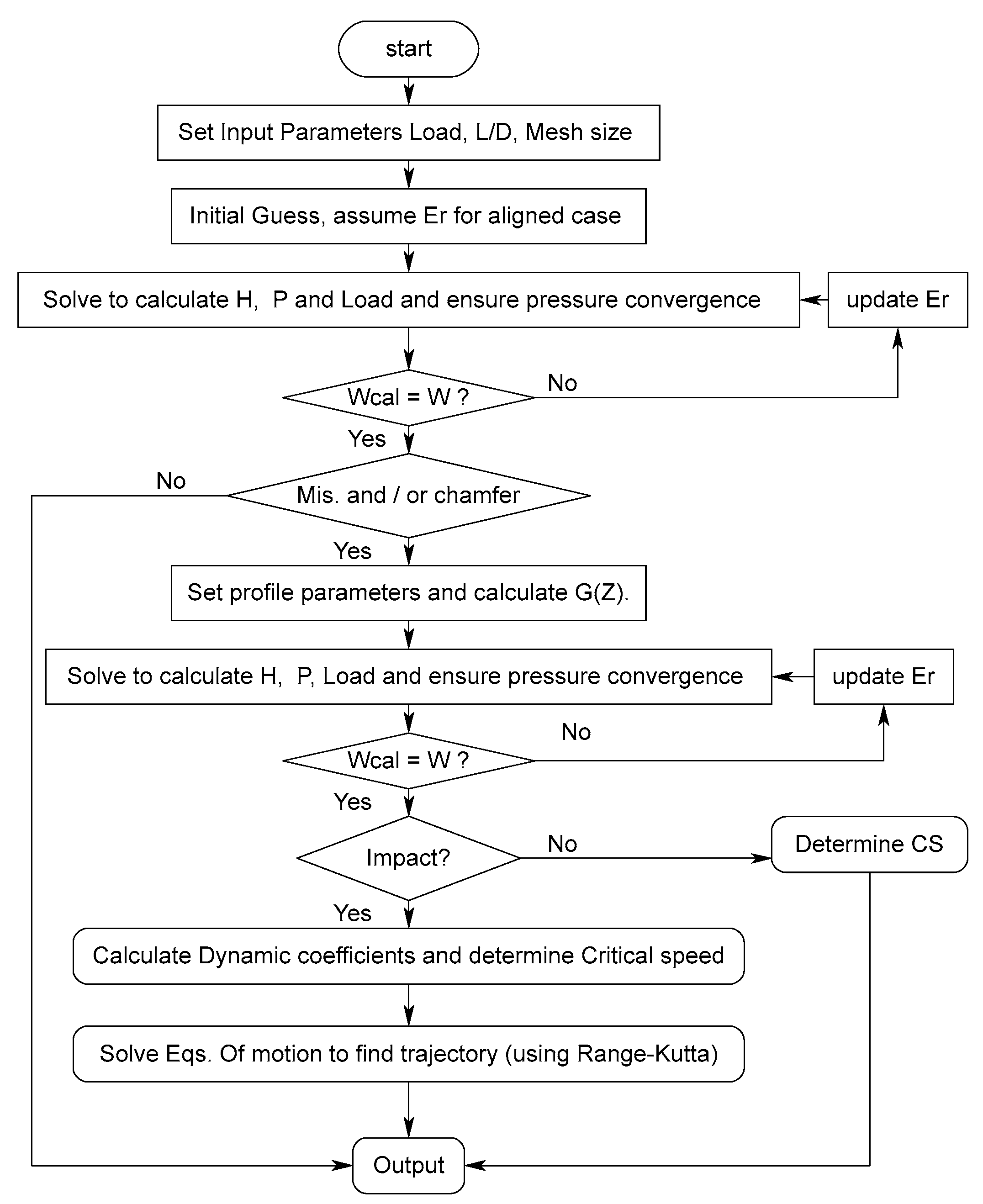
It is clear that the demand of higher power leads to an increase in the operating speed of rotary machineries, which affects the stability characteristics of the rotor bearing system. Increasing the speed under largely supported load, in addition to many other effects, leads to the presence of another problem, which is the shaft misalignment in this type of bearing system. The purpose of this paper is to improve the bearing dynamic characteristics under dynamic loads and to minimize the negative consequences of the shaft misalignment considering two forms of chamfer. These two forms are linear and curved modifications of the bearing edges, where the misalignment has the greatest effect on minimizing the lubricant layer thickness. The study will consider a numerical solution for the finite length journal bearing based on the finite difference method using the Reynolds boundary condition method to identify the cavitation zone.
The system stability under dynamic load for both forms of the chamfer is also investigated based on the solution of the equations of motion to determine the shaft center trajectory where the Runge-Kutta method is used in this solution. Furthermore, the friction coefficient will also be determined in order to evaluate the bearing modification process.

2. The Misalignment Model

The misalignment in the journal bearing is represented by the shaft axis deviation from the parallelism to the bearing axis. In general, this deviation may occur in the vertical plane, horizontal plane, or both. A 3D representation of the general case of the misalignment is illustrated in Figure 1. Such a 3D model can be used to take into consideration all possible deviations due to the shaft deformation or any errors related to the manufacturing and installation processes. This model was illustrated in detail in a previous paper by the first author of this work [39]. The dimensionless deviations in the vertical and horizontal planes, which are used to modify the film thickness equation, are given by:
Δ v z = Δ v o   1 2 Z     f o r   Z   1 / 2
Δ v z = Δ v o   2 Z 1     f o r   Z > 1 / 2
Δ h z = Δ h o   1 2 Z     f o r   Z   1 / 2
Δ h z = Δ h o   2 Z 1     f o r   Z > 1 / 2
where Δ = δ / c and Z = z / L .
In the solution of the hydrodynamic problem of misaligned journal bearings, the eccentricity and the attitude angle are no longer constant along the bearing width, which can be given by [39]:
e z = e   cos δ v z 2 + e   sin + δ h z 2
z = t a n 1 e s i n + δ h z e c o s δ v ( z )   for   z L / 2
e z = e   cos + δ v z 2 + e   sin δ h z 2
z = t a n 1 e s i n δ h z e c o s + δ v ( z )   for   z > L / 2
where and e are the attitude angle and the eccentricity distance at z = L / 2 (half bearing width), respectively. This new eccentricity is divided by c (redial clearance) to get the eccentricity ratio, which will be used together with the attitude angle calculated by these equations to determine the film thickness for the misaligned journal bearing.

3. The Chamfer Models

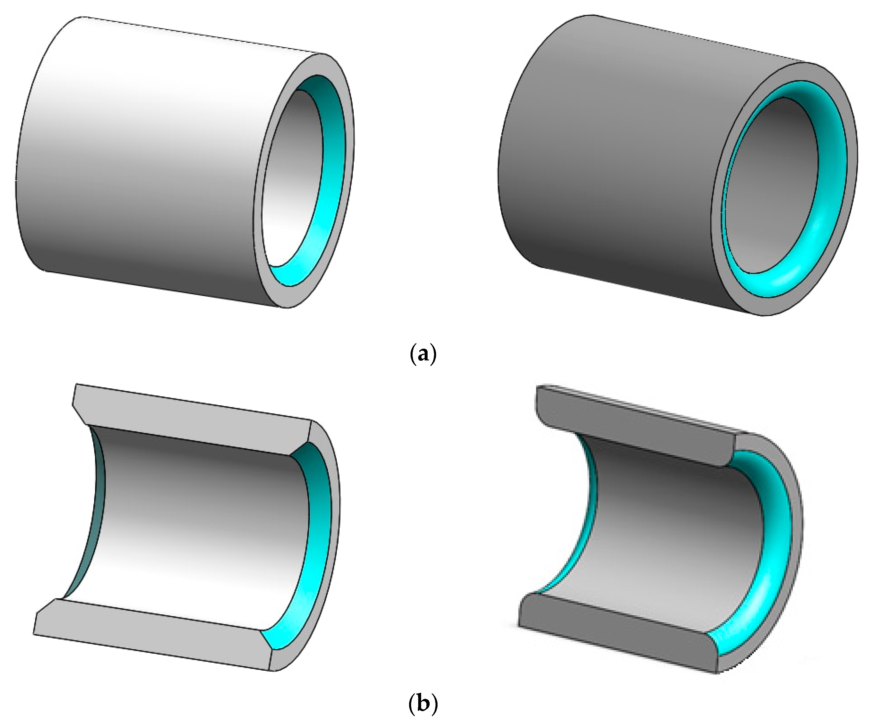
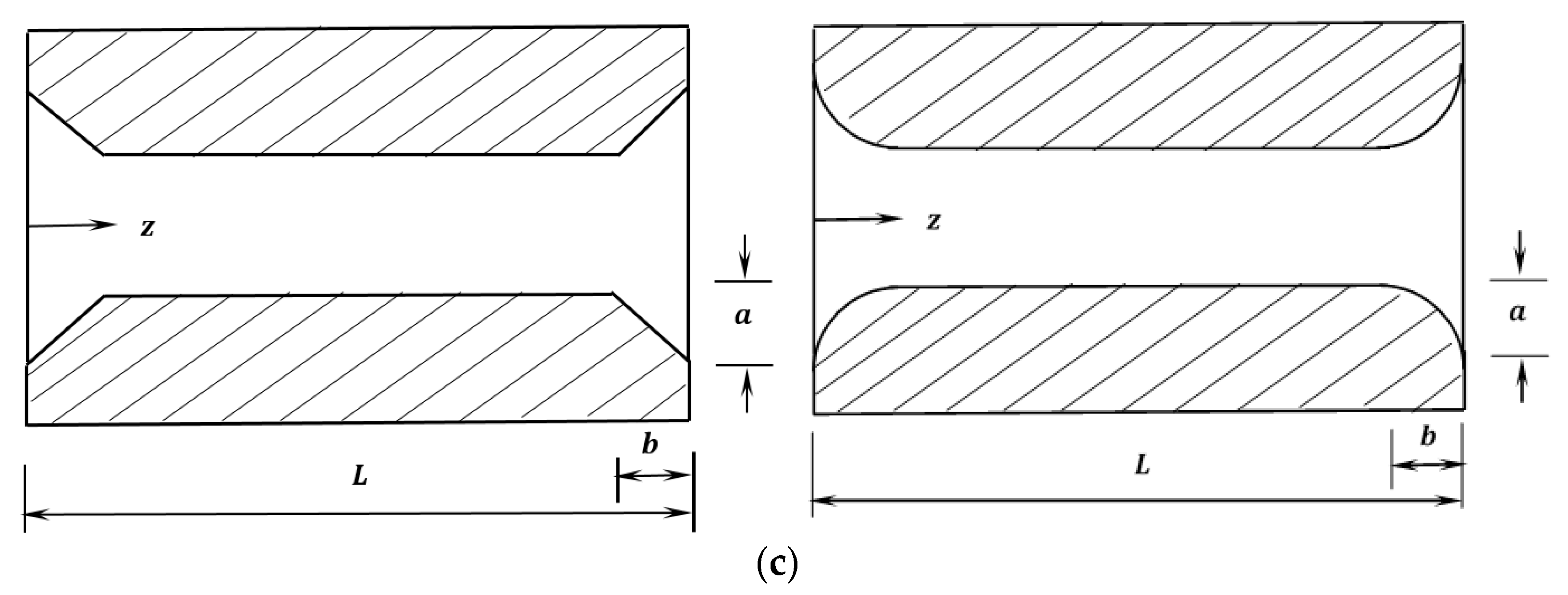
The modification of the bearing edges is performed using two forms of chamfer to examine the effect on the reduction of the negative misalignment effects as explained previously. This classification of the form of chamfer depends on the shape of the material removed from the inner surface of the bearing, as shown in Figure 2. The left side of this figure shows the first form of the modification, where the material, the inner surface shape, is modified linearly. This modification was illustrated in detail by one of the authors in a previous paper [21], which is repeated here for the purpose of comparison with the second curved form of chamfer shown on the right side of Figure 2. It can be seen that the second form ensures the continuity of slope at the start point of modification in the longitudinal direction.
The resulting gap in the circumferential direction between the shaft and the bearing for the linear chamfer is related to the position z along the bearing width, which can be given by [21]:
G Z = A   1 Z 1 B   for   Z   B
G Z = A   1 + 1 B Z 1   for   Z   1 B
G Z = 0   for   B Z   1 B
where A and B are the dimensionless parameters for the modification. These parameters are given by:
A   = a / C
B = b / L
The parameter a is the maximum height of the material removed in the radial direction at the bearing edges, and b is the distance in the longitudinal direction in which the modification is performed. A and B are scaled to the radial clearance, c, and the bearing width, L, respectively, to provide a clear understanding of the modification in terms of the main bearing design dimensions. These two parameters are used as design parameters to examine the efficiency of the modification.
For the second form of chamfer (illustrated on the right side of Figure 2), the corresponding gap in the radial direction can be given by:
G Z = A   1 B 2   Z 2 2 B Z + 1     for   Z   B
G Z = A B 2   Z 2 2 1 B Z + 1 B 2   for   Z   1 B
G Z = 0   for   B Z   1 B
The results of the previous equations can be examined by substituting the values of Z at the start (Z = 0, Z   B and Z = 1 B for Z   1 B ) and at the end of the modification ( Z = B for Z   B and Z = 1 for Z   1 B ), which must result in a zero value and A , respectively.
A schematic drawing for the two forms of the chamfer is illustrated in Figure 2c.

4. The Hydrodynamic Lubrication Problem

The governing equations for the hydrodynamic lubrication in journal bearings are the well-known Reynolds equation and the film thickness equation, which are given by [37,38] under classical hypotheses:
x ρ h 3 12 η p x + z ρ h 3 12 η p z = U m   ρ h x + ρ h t
h = c ( 1 + ε r   cos θ )
U m = U j + U b 2
where U b : bearing velocity, U j : journal velocity, and U m : mean velocity. U j = R ω and U b = 0 when the bearing is stationary. ρ , η : density and viscosity of the lubricant, respectively. The density is constant for incompressible flow. ε r : eccentricity ratio, : attitude angle, c: radial clearance, p: pressure, and h: film thickness. The squeeze term ( h t )   is zero for the steady-state condition.
In the current work, the solution of Equation (6) is based on the use of the Reynolds boundary method, which requires [39]:
P = 0   at   θ = 0
P = P θ = 0   at   θ = θ c a v
where an iterative method is used in the determination of the position of the cavitation angle θ c a v [40,41].
The governing equations are written in the solution scheme in their dimensionless forms using the following dimensionless variables for the purpose of generality:
Z = z L ,   x = R θ ,     P = p p o 6 η ω c 2 R 2   and   H = h c
where L: bearing length, H: dimensionless film thickness, P: dimensionless pressure, and   p o : the atmospheric pressure.
Therefore, Equations (6) and (7) become:
θ H 3 P θ + α Z H 3 P Z H θ = 0
where:
α = R 2 L 2 = 1 4 L / D 2
H = 1 + ε r   cos θ
The total gap between the shaft and the bearing, considering the misalignment and the chamfering models, can be determined by coupling Equations (4), (5), and (9).
Integrating the pressure field over the solution space gives the dimensionless load components [40]:
W r ¯ = 0 1 0 θ c a v P   c o s   θ   d θ   d z
W t ¯ = 0 1 0 θ c a v P   s i n   θ   d θ   d z
The total load is:
W ¯ = W r ¯ 2 + W t ¯ 2
where
W ¯ = w 6 η ω R L c R 2
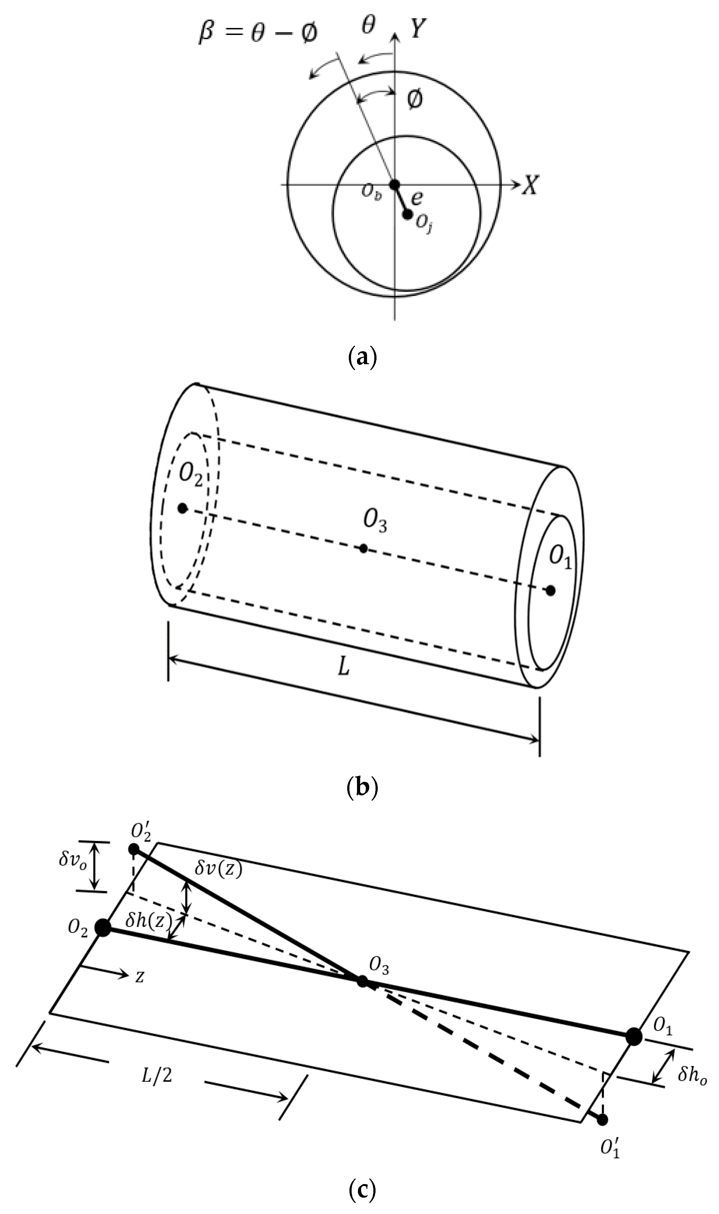
The attitude angle (the angle between the line of centers and the load (W) direction) is given by [42]:
= tan 1 W t W r

5. Dynamic Coefficients

The equations of the four stiffness coefficients ( K x x   , K x y , K y x and K y y ) and the four damping coefficients ( C x x , C x y , C y x ,   and C y y ) are derived using Reynolds equation. The following procedure of solution is explained in detail in a previous work of the authors [37].
x h 3 12 η p x + z h 3 12 η p z = U 2   h x + h t
The equation of film thickness under the dynamic condition is [4]:
h = h 0 + Δ x cos θ + Δ y sin θ
Differentiation of Equation (14) with respect to time yields:
h t = Δ x ˙ cos θ + Δ y ˙ sin θ
Substituting Equation (15) into Equation (13) gives:
x h 3 12 η p x + z h 3 12 η p z = U 2   h x + Δ x ˙ cos θ + Δ y ˙ sin θ
Equation (16) can be written in a dimensionless form as:
θ H 3 P θ + α Z H 3 P Z = H θ + 2 ( Δ Y ˙ sin θ + Δ X   ˙ c o s   θ )
where X ˙ = R x ˙ U c   , Y ˙ = R y ˙ U c   .
It is worth mentioning that the same downward direction of the x -axis in the work of Lund and Thomson [4] is used in this section, and then the direction is reversed to ensure the consistency of the results with the system of coordinates adopted in this work.
The resultant forces are given by [4] and [43]:
F x = 0 1 0 θ c a v P cos θ d θ   d Z
F y = 0 1 0 θ c a v P sin θ d θ   d Z
which are functions of x ,     y ,   x ˙ , and y ˙ ( F x = F x ( x ,   y ,     x ˙ , y ˙ ) and F y = F y ( x ,   y ,   x ˙ , y ˙ ))
The resultant force is:
F = F x 2 + F y 2
The dynamic coefficients can be written in the following form [44]:
k = k x x k x y k y x k y y = F x X F x Y F y x F y Y
c = c x x c x y c y x c y y = F x X ˙ F x Y ˙ F y X ˙ F y Y ˙
These coefficients are written in the following form, which is suggested by [4]:
K x x = c   k x x F ,   K x y = c   k x y F   ,   K y x = c   k y x F   ,   K y y = c   k y y F
C x x = c   ω   c x x F   ,   C x y = c   ω   c x y F     ,       C y x = c   ω   c y x F ,   C y y = c   ω   c y y F
Therefore, following the previous definitions of the dynamic coefficients, the equations of these coefficients can be given by:
K x x = 0 1 0 2 π P x   c o s   θ   d θ   d z
K x y = 0 1 0 2 π P y   c o s   θ   d θ   d z
K y x = 0 1 0 2 π P x   s i n   θ   d θ   d z
K y y = 0 1 0 2 π P y   s i n   θ   d θ   d z
C x x = 0 1 0 2 π P x ˙   c o s   θ   d θ   d z
C x y = 0 1 0 2 π P y ˙   c o s   θ   d θ   d z
C y x = 0 1 0 2 π P x ˙   s i n   θ   d θ   d z
C y y = 0 1 0 2 π P y ˙   s i n   θ   d θ   d z
where P x = P X , P y = P Y , P x ˙ = P X ˙   , and P y ˙ = P Y ˙ .
The required derivatives for the determination of the dynamic coefficients are evaluated as follows:
H t = Δ X ˙ cos θ + Δ Y ˙ sin θ
H X = cos θ
H Y = sin θ
H θ = Δ X   sin θ + Δ Y cos θ
The differentiation with respect to X and Y gives:
θ H 3 P x θ + α Z H 3 P x Z = θ 3 H 2 cos θ P θ α Z 3 H 2 cos θ P Z sin θ
θ H 3 P y θ + α Z H 3 P y Z = θ 3 H 2 sin θ P θ α Z 3 H 2 sin θ P Z cos θ
The differentiation with respect to X ˙ and Y ˙ , respectively, yields:
θ H 3 P x ˙ θ + α Z H 3 P x ˙ Z = cos θ
θ H 3 P y ˙ θ + α Z H 3 P y ˙ Z = sin θ
The last four Equations (23)–(26) will be solved numerically in the section of the numerical solution.

6. Stability of Journal Bearing

The critical speed of the journal bearing is determined based on the solution of the rotor equations of motion. These equations of motion can be written for a rigid rotor supported by two bearings, as shown in Figure 3 [23]:
m   x ¨ = F x + f e x f sin Ω t
m   y ¨ = F y + f e y f cos Ω t + W
where   F x   and   F y are the bearing forces,   f e x   and   f e y are the external loads, f is the unbalance force, and x ,   y are the whirling axes of the shaft center as shown in Figure 3b.
The previous equations can be written in a dimensionless form as:
M ¯ X ¨ = F ¯ x + F ¯ e x Ru ¯   sin   T
M ¯ Y ¨ = F ¯ y + F ¯ e y Ru ¯   cos   T + 1
where F ¯ x = F x W , M ¯ = m   c   Ω 2 W , and Ru ¯ = m u   r Ω 2 W .
The impact load is given by [23]:
F ¯ e y = F ¯ e y o e a 2 T / Ω t o 2
and   F ¯ e x = 0
The solution of the journal equations of motion is used in determining the dynamic characteristics of the bearing system [45,46]. The critical speed of the shaft can be determined by neglecting the unbalance and the external forces. Therefore, the resulting linear equations are [23,47]:
M ¯ X ¨ + F ¯ x = 0
M ¯ Y ¨ + F ¯ y = 0
The bearing forces, F ¯ x and F ¯ y , can be written in the following form for small displacements around the shaft equilibrium position [23]:
F ¯ x = K x x   X + K x y   Y + C x x   X ˙ + C x y   Y ˙
F ¯ y = K y x   X + K y y   Y + C y x   X ˙ + C y y   Y ˙
Substitution of Equations (34) and (35) in Equations (32) and (33) yields:
M ¯   X ¨ + K x x   X + K x y   Y + C x x   X ˙ + C x y   Y ˙ = 0
M ¯   Y ¨ + K y x   X + K y y   Y + C y x   X ˙ + C y y   Y ˙ = 0
The solution for these equations is [39]:
X = A e i λ t ,   Y = B e i λ t
Substitution of these solutions in Equations (36) and (37), respectively, gives,
k e q K x x k e q K y y λ 2   C x x   C y y K x y   K y x + λ 2   C x y C y x = 0
where
λ = k e q K x x K e q K y y K x y   K y x C x x   C y y C x y C y x
K e q = K x x   C y y + K y y C x x K y x C x y K x y C y x C x x + C y y
The critical speed ( Ω c r i t ) is:
Ω c r i t = k e q λ

7. Coefficient of Friction

The coefficient of friction is determined in this paper using the model suggested by Lund and Thomsen [4], which is:
f = F f W
where F f = P u is the friction force, W is the total supported load,   u = R ω , and P is the power loss, which is given by:
P = ω η R 3 ω 0 θ l d θ h + 1 2 ε r ( F X s i n F Y c o s )
where the bearing forces ( F X and F Y ) can be easily determined by the integration of the resulting pressure field.

8. Numerical Solution

The full numerical solution of the hydrodynamic problem of misaligned journal bearings considering bearing edges modification consists of discretizing the governing equations using the finite difference method. The discretization of the governing equations is explained in detail in the authors’ previous work [21,39]. This discretization results in the following equation, which can be used to determine the pressure value at each point in the solution space:
P i , j = 1 β H b 3   P i + 1 , j + H a 3   P i 1 , j + α C 2 H c 3   P i , j + 1 + α C 2 H d 3   P i , j 1 C 1 H i + 1 , j + C 1 H i 1 , j
where C 1 = Δ θ 2 , α = R 2 L 2 ,   β = H b 3 + H a 3 + α   C 2 H c 3 + α   C 2 H d 3 ,   C 2 = ( Δ θ ) 2 ( Δ Z ) 2 , Δ θ and Δ Z are the mesh steps in the circumferential and longitudinal direction of the bearing.
The corresponding equation of the film thickness at any i ,     j position in the solution space is given by:
H i , j = 1 + ε r Z cos ( θ i , j )
The overrelaxed Gauss-Seidel method is used in the numerical solution of this problem. The convergence of the solution involves both the pressure and load convergences. The pressure convergence criterion is P i , j n e w P i , j o l d P i , j o l d < 10 7 . Satisfying this convergence criterion for the pressure is followed by calculating the bearing forces in both directions to determine the load-carrying capacity of the bearing. This calculated load is compared with the actual designed load using a load convergence criterion that must satisfy a tolerance of 10 5 . If the calculated load is outside this limit, the solution is repeated using an updated value for the eccentricity ratio. This updating of the eccentricity ratio is continued until both the load and the pressure criteria are satisfied. The designed load considered in this work corresponds to that of a perfectly aligned bearing when the eccentricity ratio is 0.6. Following this convergence, the dynamic coefficients of the bearing system can be calculated numerically using the relevant equations mentioned previously. Discretizing the related Equations (9) and (20)–(22) leads to the following general equation, which also requires a numerical solution to find the pressure derivative ( P ¯ i . j ):
P ¯ i . j = 1 ψ Δ θ 2   R H S H b 3   P ¯ i + 1 . j H a 3   P ¯ i 1 . j α C 2 H c 3   P ¯ i . j + 1 α C 2 H d 3   P ¯ i . j 1 + C 1 H i + 1 . j C 1 H i 1 . j
where C 1 = Δ θ 2 , α = R 2 L 2 , ψ = H b 3 H a 3 α   C 2 H c 3 α   C 2 H d 3 , C 2 = ( Δ θ ) 2 ( Δ Z ) 2 .
The solution of the previous equation requires the determination of the right-hand side (RHS) of Equations (23)–(26), which can be given by:
R H S 19 = 3 cos θ b H b 2 + 3 cos θ a H a 2 P i . j Δ θ 2 3 cos θ b H b 2 P i + 1 . j Δ θ 2 3 cos θ a H a 2 P i 1 . j Δ θ 2 +
α 3 cos θ c H c 2 + 3 cos θ d H d 2 P i . j Δ Z 2 α 3 cos θ c H c 2 P i . j + 1 Δ Z 2 α 3 cos θ d H d 2 P i . j 1 Δ Z 2 sin θ
R H S 20 = 3 sin θ b H b 2 + 3 sin θ a H a 2 P i . j Δ θ 2 3 sin θ b H b 2 P i + 1 . j Δ θ 2 3 sin θ a H a 2 P i 1 . j Δ θ 2 +
α 3 sin θ c H c 2 + 3 sin θ d H d 2 P i . j Δ Z 2 α 3 sin θ c H c 2 P i . j + 1 Δ Z 2 α 3 sin θ d H d 2 P i . j 1 Δ Z 2 cos θ
R H S 21 = cos θ i . j
R H S 22 = sin θ i . j
The determination of these coefficients is followed by solving the equations of motion using the Runge-Kutta method to find the response (shaft center trajectory) under impact load. The steps of the numerical solution are summarized by the flow chart shown in Figure 4.

9. Results and Discussion

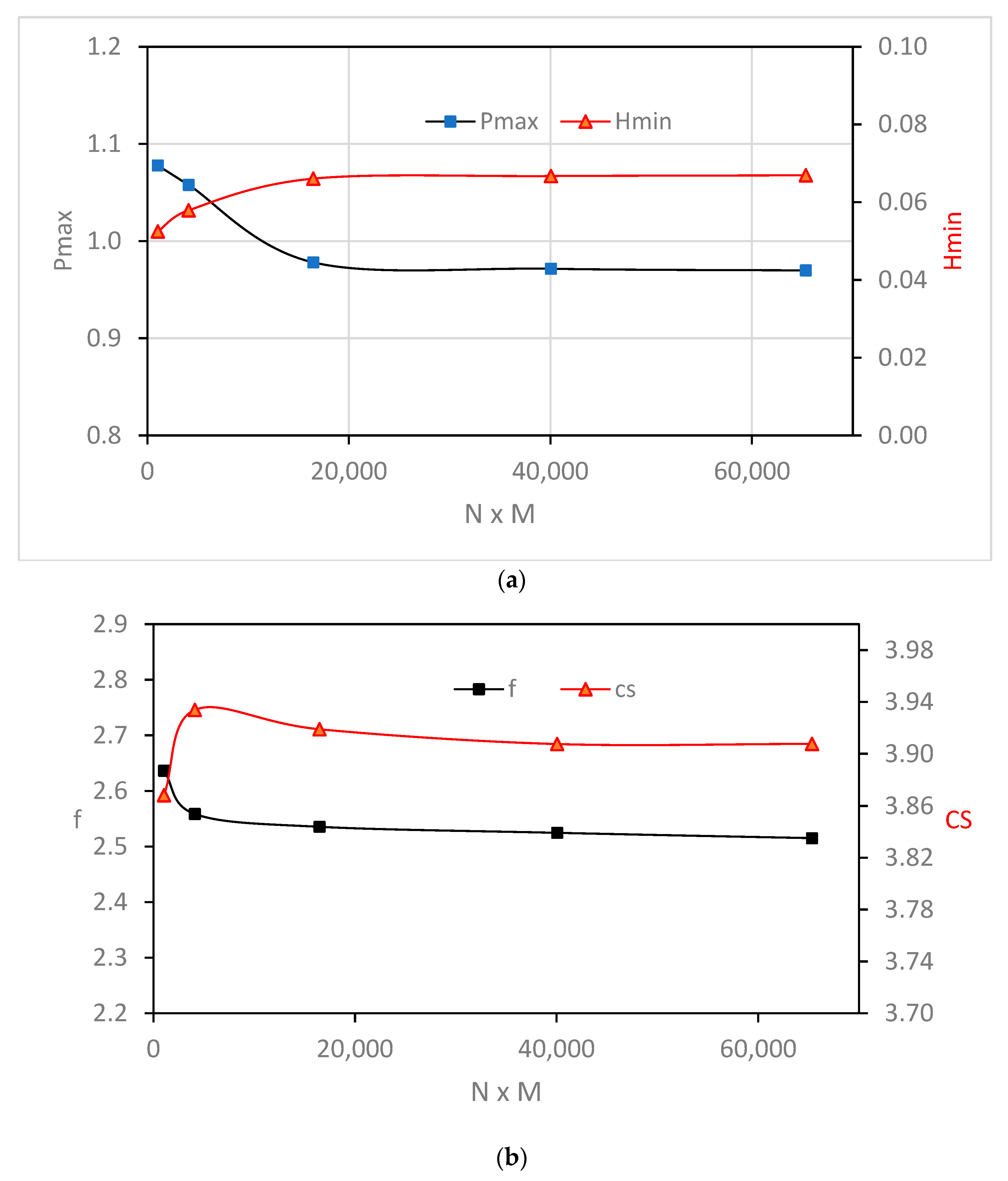
The presented results are performed for a finite-length journal bearing where L / D = 1.25 . Before examining the effects of chamfer forms and their related parameters on the characteristics of misalignment bearing, the worst case of the misalignment problem is solved using a wide range of nodal points to ensure the independence of the analysis on the number of points in the finite difference solution scheme. The total number of nodes is N M , where N and M are the numbers of nodes in the circumferential and longitudinal direction, respectively. Part of the results related to this test is shown in Figure 5, where Figure 5a shows the variation of Pmax and Hmin with the number of nodes, and Figure 5b shows the corresponding results for the critical speed and coefficient of friction. It can be seen that the change in these main results is trivial when N M 16 , 471 (third point in the figures).
The numerical results of the current work are compared with the well-known work of Lund and Thomson [4] for different values of the eccentricity ratio when L / D = 0.5 as shown in Table 1. The compared results are those for a perfectly aligned bearing. The results are very close to each other in particular when ε r 0.655 , where the difference is less than one percent. However, very good agreement is also obtained for higher values of the eccentricity ratio, where the difference is less than four percent.
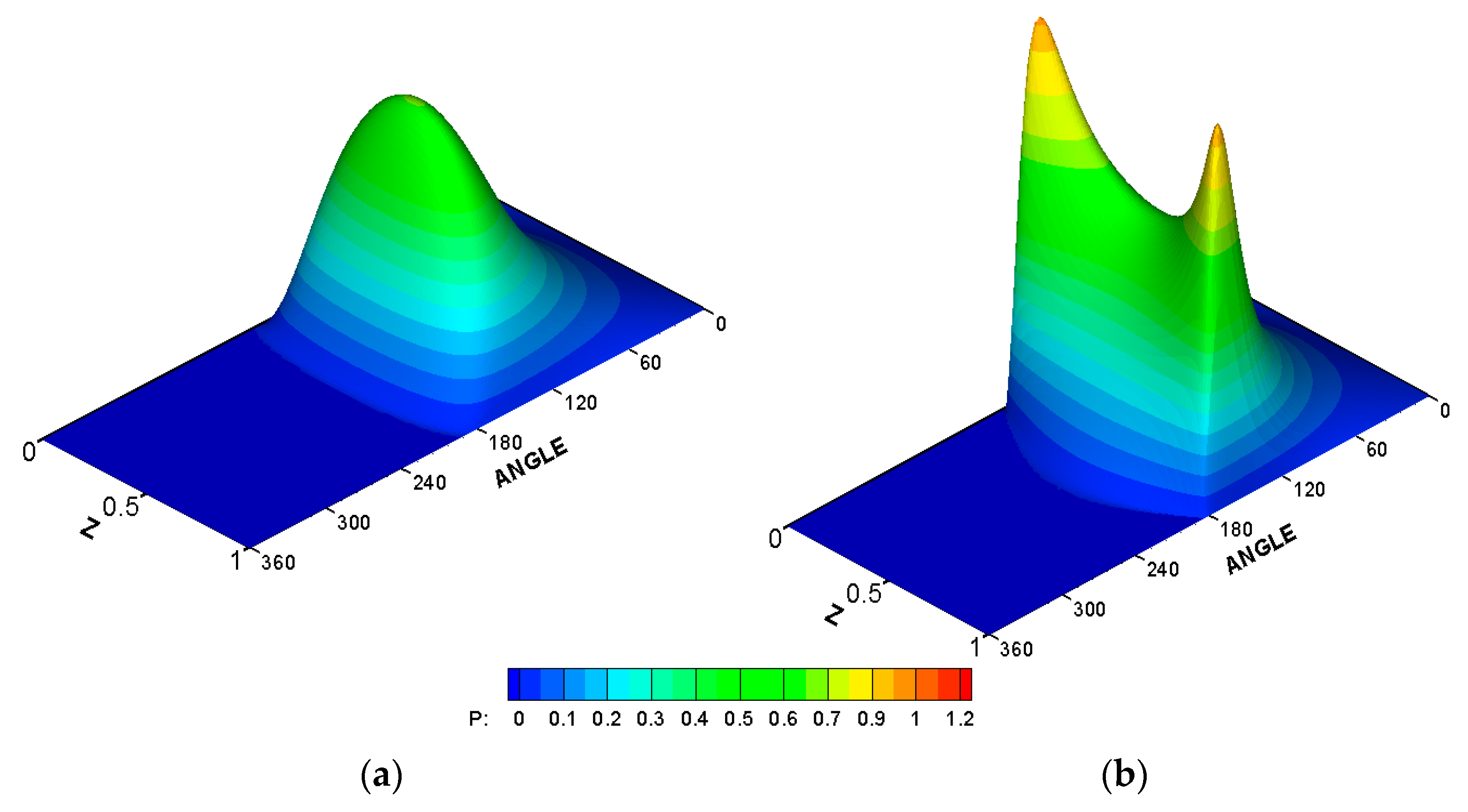
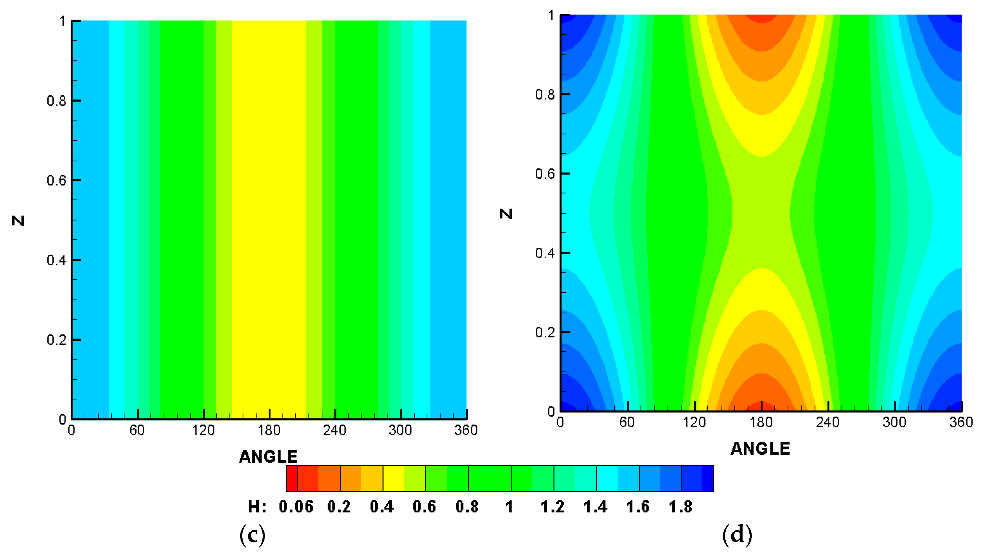
It is well known that the presence of misalignment affects film thickness and pressure distribution. Its effects reflect on the values and also the shape of their distributions. Figure 6 illustrates these effects, where the left side shows the results of a perfectly aligned bearing (3D pressure and 2D film thickness), and the right side illustrates the corresponding results for a misaligned bearing. The 3D misalignment parameters in this figure are Δ h = Δ v = 0.58 and L / D = 1.25 . This level of misalignment is chosen as an extreme case where the film thickness is reduced significantly, as will be explained later. The results in this figure clearly illustrate the previously mentioned effects of misalignment. In the aligned case, the pressure is uniformly distributed, and the film thickness is constant along the bearing width at each angle in the circumferential direction. On the other hand, the misalignment increases the maximum pressure and reduces the minimum film thickness, respectively. Furthermore, the pressure distribution is no longer uniform, and the film thickness varies along the bearing width at each position along the circumferential direction.
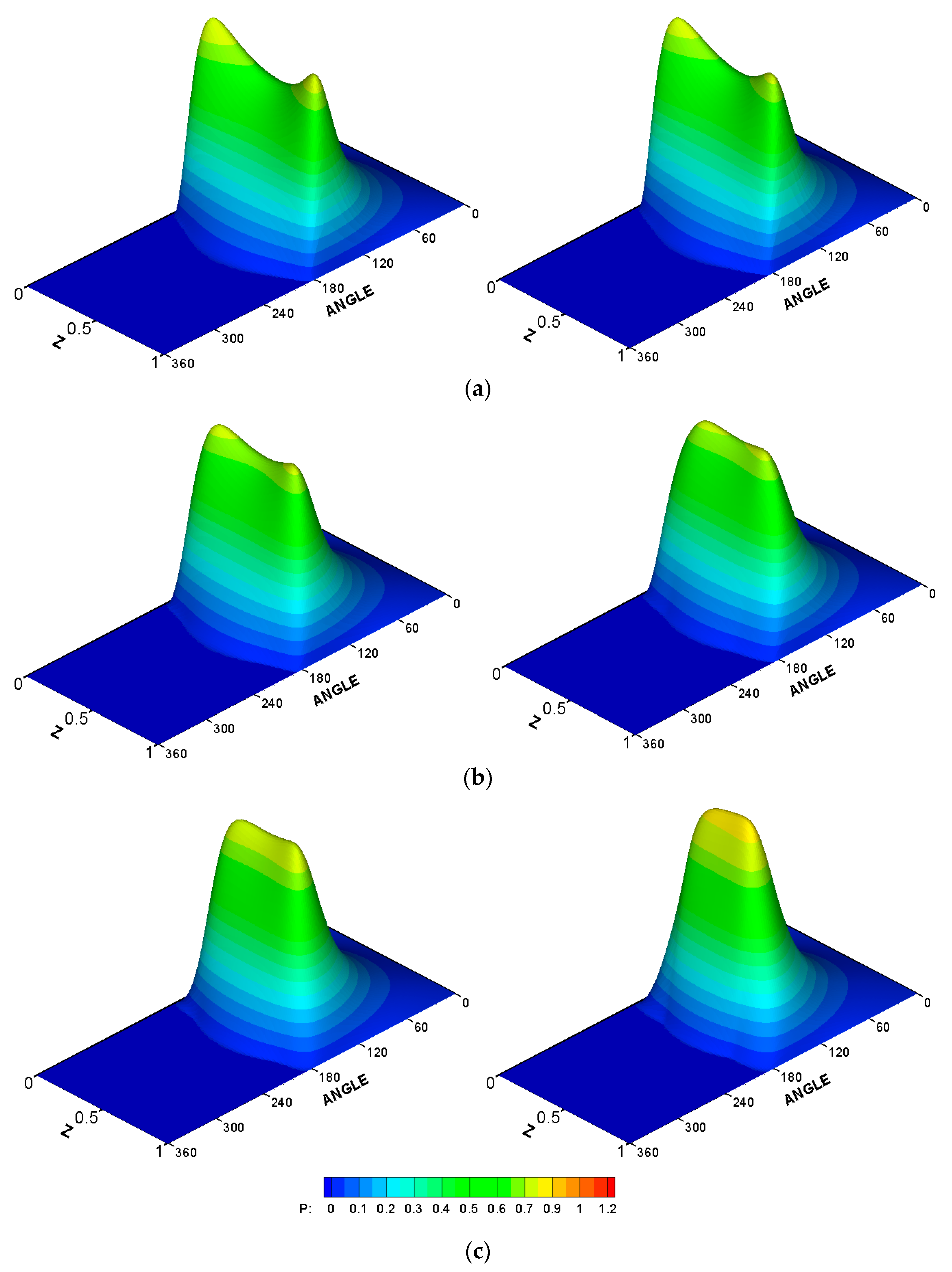
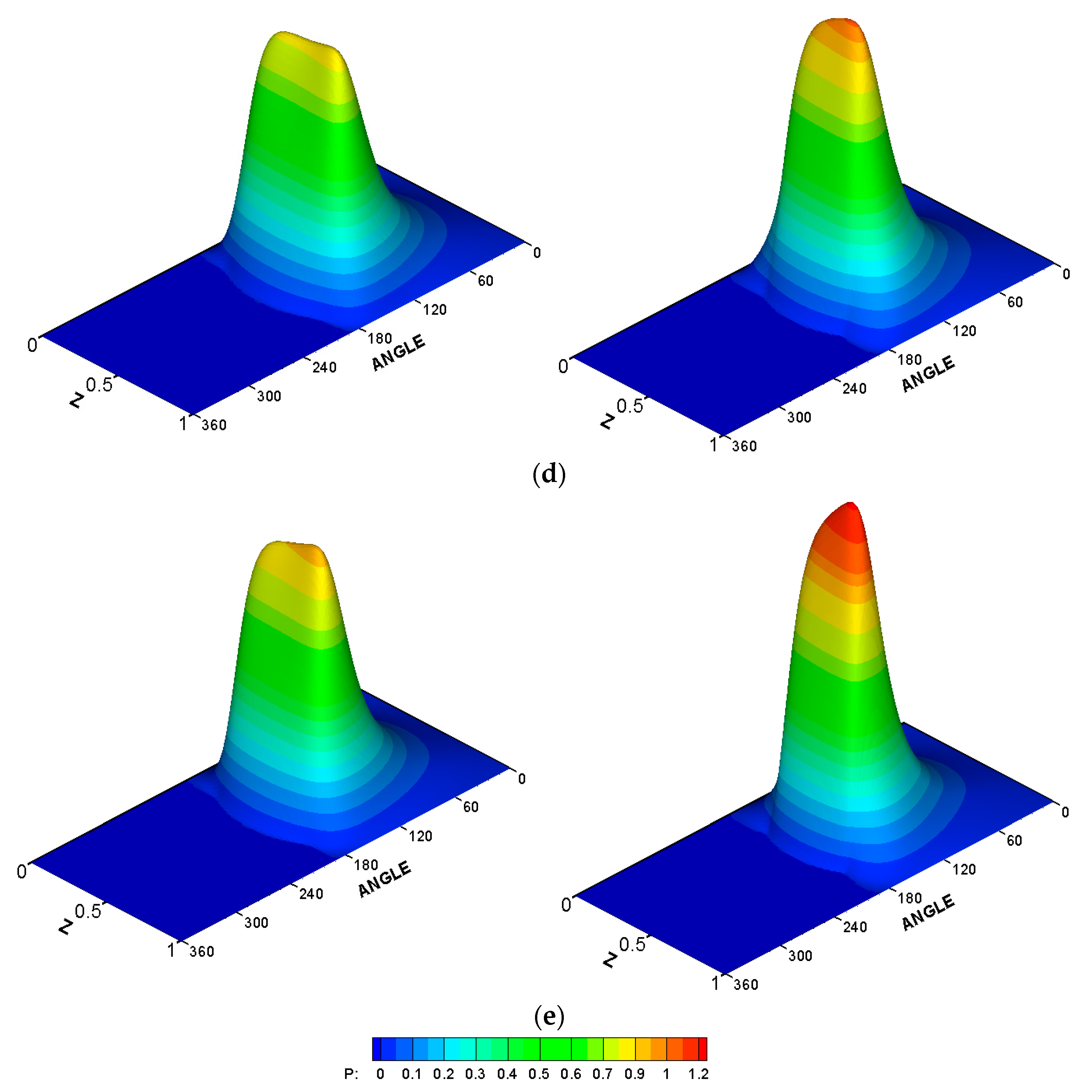
The high level of pressure and extremely low level of film thickness will certainly have an effect on the bearing life and its performance. The level of film thickness can be elevated under such operating conditions by lowering the bearing load to avoid the increase of the wear rate under such a thin layer of lubricant. However, this is not a practical solution as the bearing is designed in the first place to support a certain load (or load with specified tolerances) and to operate with a corresponding acceptable level of minimum film thickness that separates the shaft and bearing surfaces. This design strategy can be ensured by introducing the chamfer at the bearing edges where the inclination of the journal due to misalignment has its maximum effect in lowering the film thickness value. In this paper, two forms of chamfer are considered: the linear chamfer and a second-order modification, as explained in the previous sections. The linear chamfer has a sudden change in the profile of the bearing in the longitudinal direction, while the curved modification ensures the continuity of the bearing profile with equal slope at the point where the chamfer is started. The effects of these two forms of the chamfer on the 3D pressure distribution is shown in Figure 7 for different values of the chamfer parameter. The left side of this figure shows the results of the second-order curve chamfer, while the right side illustrates the corresponding results when the chamfer is linear. The values of the chamfer parameter A in Figure 7a–e are 0.1, 0.25, 0.5, 0.7, and 1, respectively, and the value of B is 0.25, which shows a best chosen value for the modification in the longitudinal direction (results are not shown for the effect of B parameter in order to summarize the results shown in this figure). It is worth mentioning that the values of chamfer parameters A and B are scaled to the clearance, C, and the bearing length, L, respectively, to give a clearer picture of the amount of material removal from the bearing inner surface in terms of the bearing geometry. When A = 1, for example, this means that the chamfer height is equal to the clearance C, and when B = 0.25, the chamfer is started at one-fourth of the bearing width from each side of the bearing. It can be seen that using lower values of A in the two forms of chamfer reduces the maximum pressure and positively changes the shape of distribution resulting from the misalignment (it becomes closer to the aligned case) as shown in Figure 7a–c. As the value of A increased, the linear chamfer led to higher pressure values in comparison with the curved chamfer, as shown in Figure 7d,e. This behavior will be discussed in detail in the next figures.
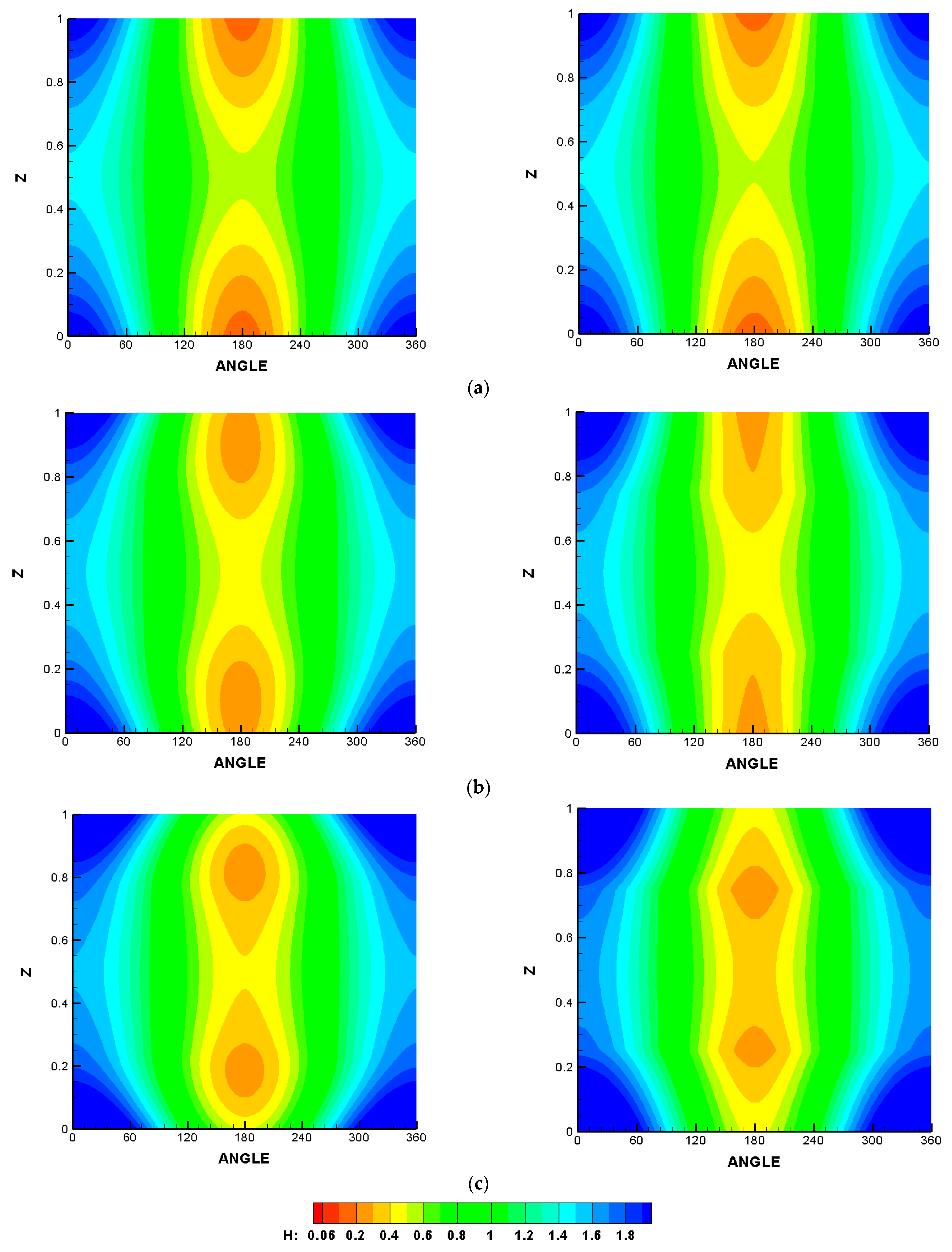
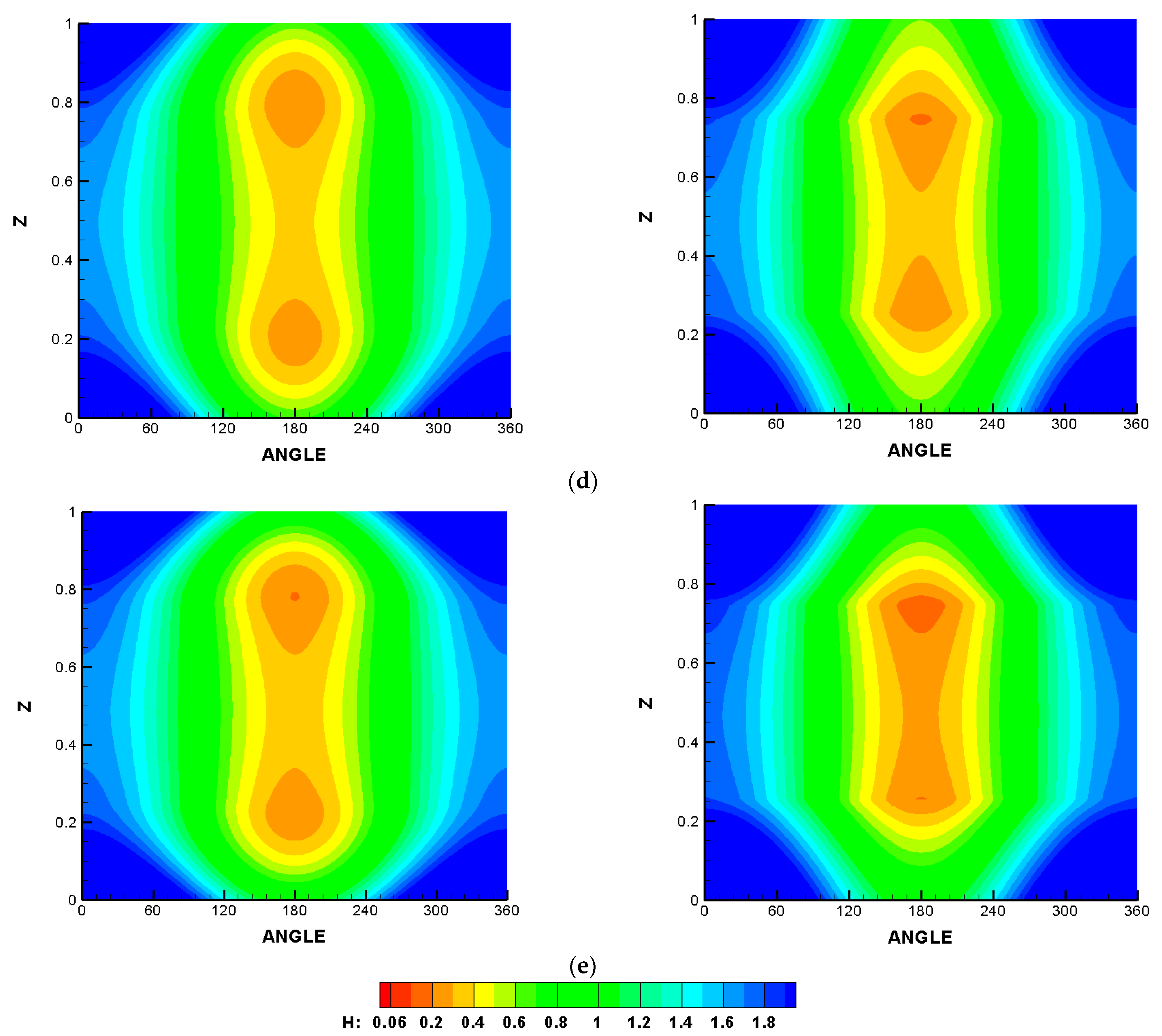
The effect of the chamfer on the film thickness is illustrated in Figure 8 using the same chamfer parameters for the cases illustrated in the previous figure (3D pressure distribution). Similarly, the left side of this figure shows the results of the second-order curve chamfer, whereas the right side illustrates the corresponding results when the chamfer is linear. The values of the chamfer parameter A in Figure 8a–e are 0.1, 0.25, 0.5, 0.7, and 1, respectively, and the value of B is 0.25. In general, the film thickness contours show sharp edges between the levels in the case of linear chamfer (right side), particularly for higher values of A. On the other hand, the curved chamfer produces film thickness levels with a continuous slope (left side). It can be seen that using different values of A in the two forms of chamfer increases the film thickness levels in all cases in comparison with the misalignment case shown in Figure 6d. However, higher values of A lead to an increase in the maximum pressure values, as shown in the previous figure, which requires an optimum value for A, as will be seen later.
To investigate the consequences of the chamfer in detail, Table 2 summarizes the effect of misalignment on Pmax, Hmin, and CS when the 3D misalignment parameters are Δ v = Δ h = 0.58 . It can be seen that such an extreme case of misalignment increases the critical speed by 46.28%, which represents a significant improvement, but at the same time it causes a 51.77% increase in Pmax and a 98.35% reduction in Hmin. The introduction of the chamfer, as will be illustrated in the next figure, will balance the benefit of increasing the critical speed and helps reduce Pmax and increase Hmin.
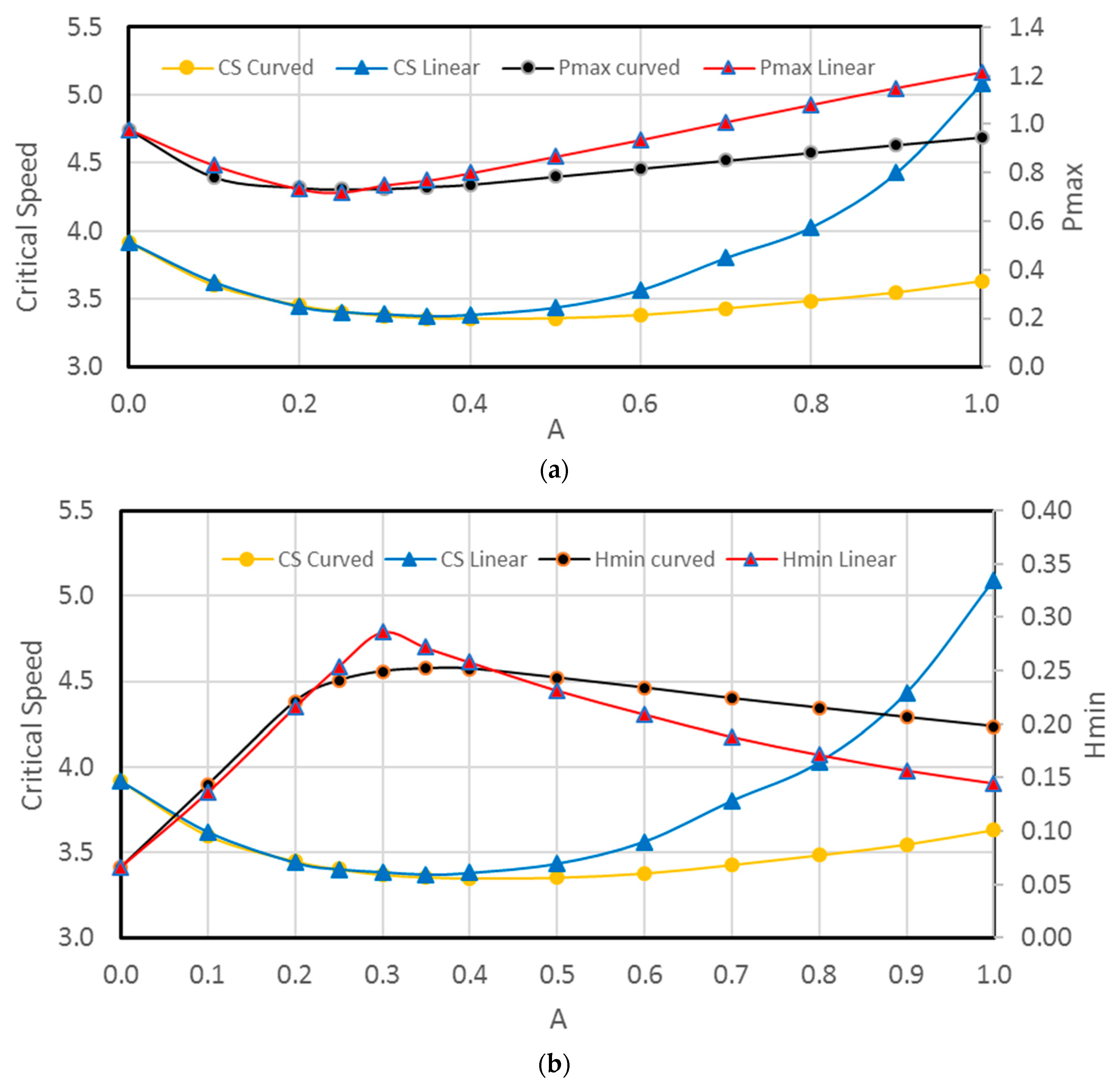
The outcome of the previous results related to the effects of the form of chamfer and chamfer parameters is discussed in more detail as illustrated in Figure 9. The investigation is extended to consider the chamfer’s effect on the system’s critical speed. Figure 9a shows the variation of the maximum pressure and the critical speed with the change in chamfer parameter A. It can be seen that the two forms of chamfer give very close results for Pmax and CS when A 0.35 . When A 0.4 , the linear chamfer produces higher CS, but there is also an increase in the values of Pmax, which represents a negative consequence of the chamfer. In general, the curved chamfer produces less Pmax for all A values with an optimum value of A = 0.25 . The corresponding results for Hmin are shown in Figure 9b. The results of CS are repeated in this figure for the purpose of clarity of the comparison. The two forms of chamfer give very close results when A 0.25 : the linear chamfer produces thicker film levels when 0.3 < A 0.4 , and the curved chamfer produces higher film levels when A > 0.4 .
Based on the results presented in the previous figure, it can be concluded that both forms of the chamfer can be beneficial when A = 0.25 ; for higher values of A, the curved chamfer is preferable in terms of Pmax and Hmin and also improves the level of critical speed to an acceptable degree compared with the aligned case. Table 3 summarizes this conclusion for the cases of A = 0.25 and A = 0.7 . As the misalignment increases Pmax, introducing the linear or the curved chamfer decreases Pmax when A = 0.25, but when A = 0.7, the linear chamfer increases slightly the Pmax in contrast with the curved chamfer where Pmax is still less than the corresponding value of the misaligned case. In both cases, the film thickness level is improved significantly, which is a significant outcome as the chamfer increases the level of minimum film thickness in comparison with the misalignment case for all the considered values of A. Furthermore, the critical speed in all cases is also higher than that of the aligned case, which represents an additional benefit for the bearing chamfering. However, the discontinuity in the slope of the bearing profile in the longitudinal direction resulting from the linear chamfer requires more investigation in terms of the deformation of the bearing inner surface, which in itself requires an elastohydrodynamic lubrication analysis. Such an analysis will explain whether the slope discontinuity will cause a significant pressure spike or not. The curved chamfer is less likely to cause such a pressure spike under the relatively low-pressure level in journal bearings, particularly without a sudden change in the profile. Therefore, the curved chamfer is preferable from this point of view.
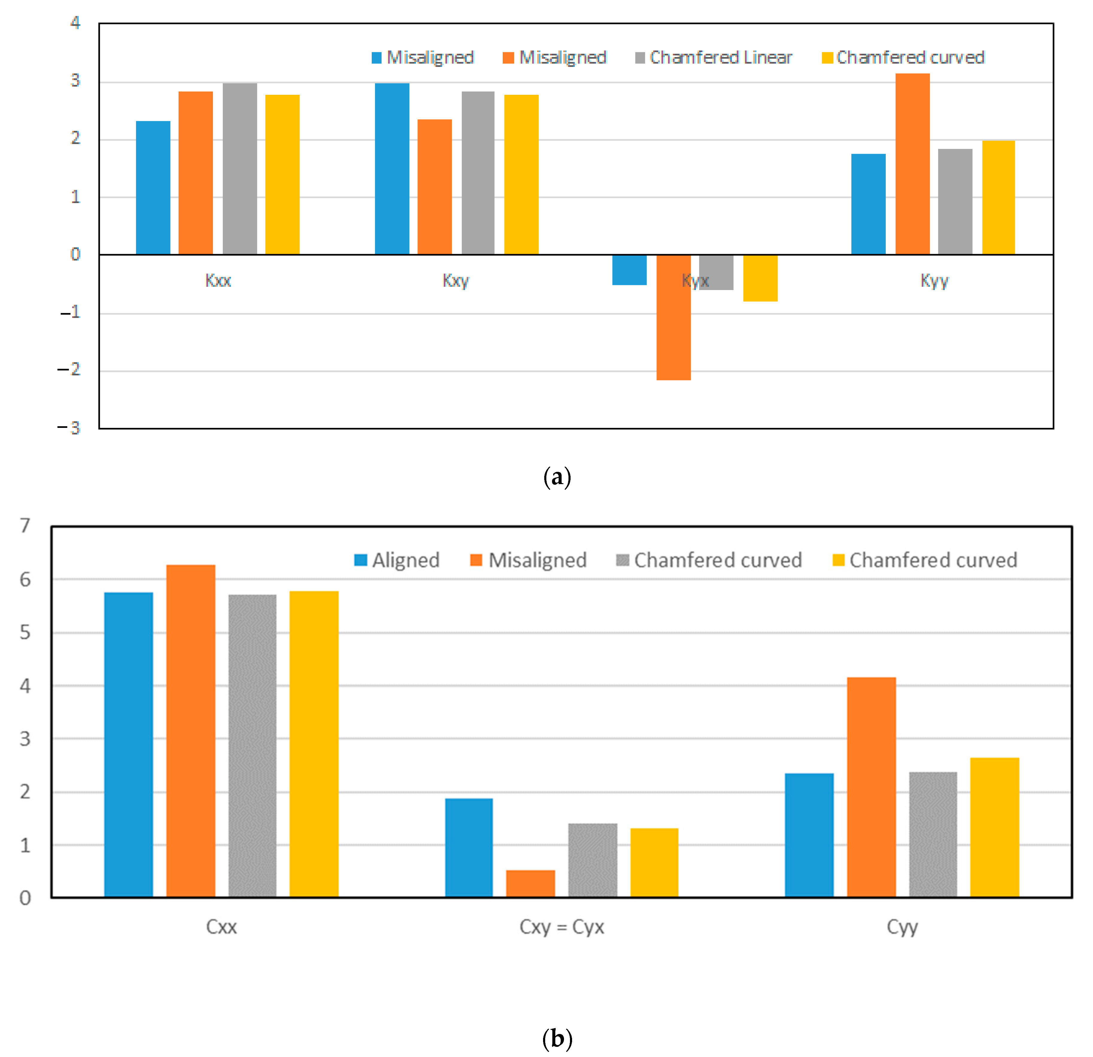
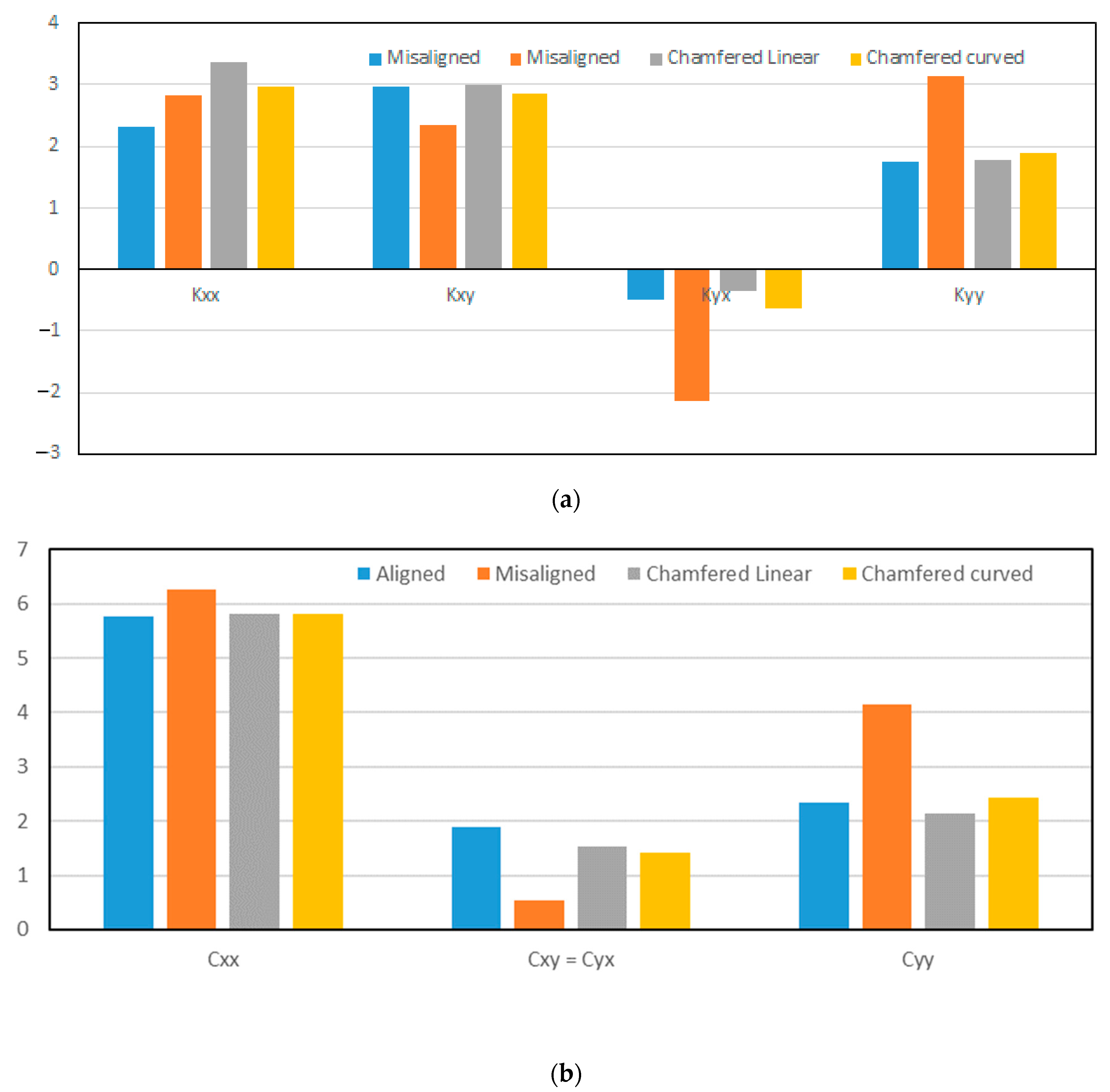
The change in the critical speed is a result of the change in the dynamic coefficients, which is related to the change in the pressure distribution due to misalignment, and also a result of introducing the chamfer. The effect of a chamfer on the stiffness and damping coefficients is shown in Figure 10 and Figure 11 when A = 0.25 and A = 0.7, respectively. In general, both forms of chamfer show the same attitude in bringing back the values of the coefficients toward the corresponding values of the aligned case.
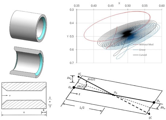
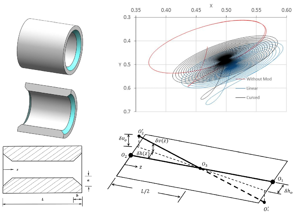
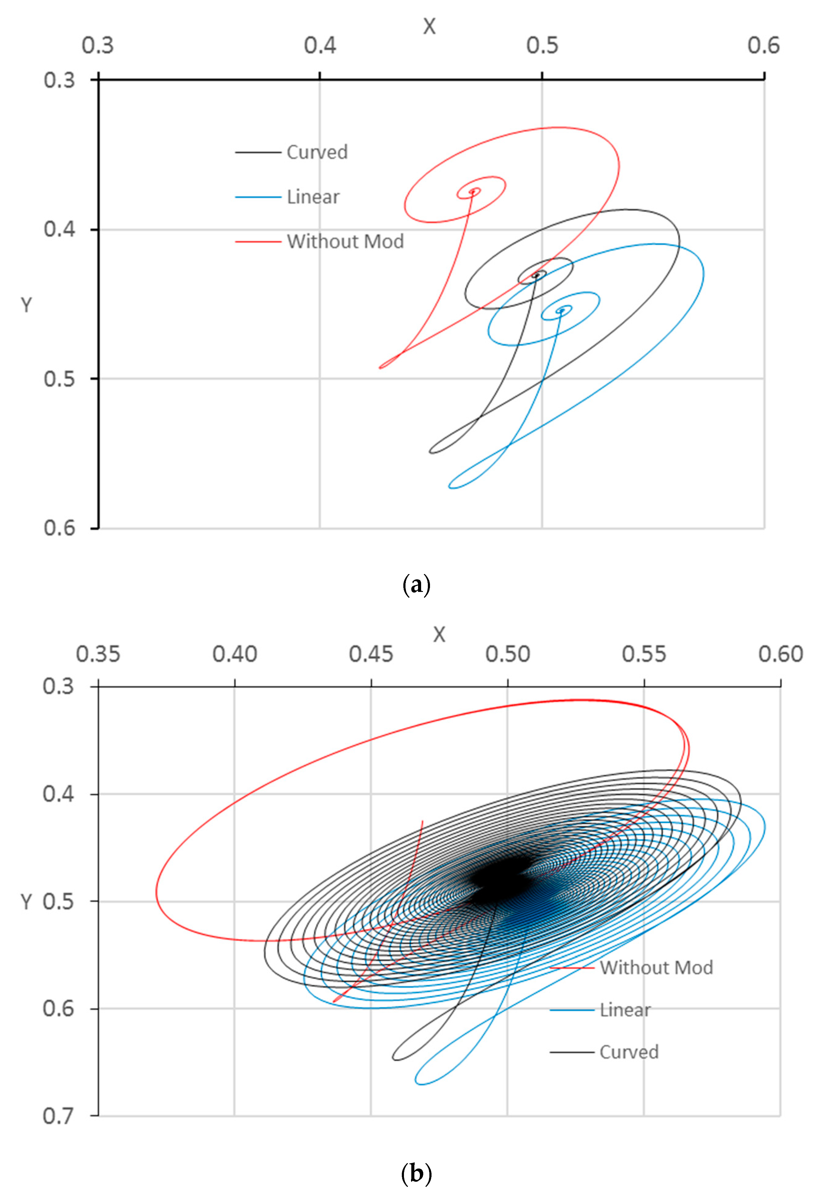
The stability of the system is examined in this work under impact load. Applying an impact load deviates the journal center from its steady-state position. If the system is stable, the journal center returns to the steady-state position after a period of time, and if the journal is at a critical situation, the journal center will keep rotating around the steady-state position on the same path. On the other hand, if the system is unstable, the journal center will rotate around the steady-state position and the amplitude will increase with time until the journal hits the bearing wall. Figure 12 shows the trajectories of the journal center for these three cases when the bearing is unchamfered or modified with a curved or linear chamfer in order to examine the system stability for the chamfered bearing in comparison with the perfectly aligned bearing. Figure 12a shows the trajectories for these three bearings when the system operates at 2500 rpm, which is below the critical speed of the perfectly aligned bearing. It can be seen that all three journals return to the steady-state position after the deviation due to impact load. The trajectory for the shaft center for bearing with the curved chamfer (black line) is closer to the aligned case. Figure 12b shows the trajectories of the centers of the bearings under impact load when the system operates at the critical speed of the aligned case. The trajectories of both chamfered bearings show that the bearing centers return to the steady-state position, while the corresponding center of the aligned case keeps rotating around the steady-state position on a fixed path as the critical speed of the chamfered bearing is greater than that of the aligned bearing in both forms of the chamfer. 
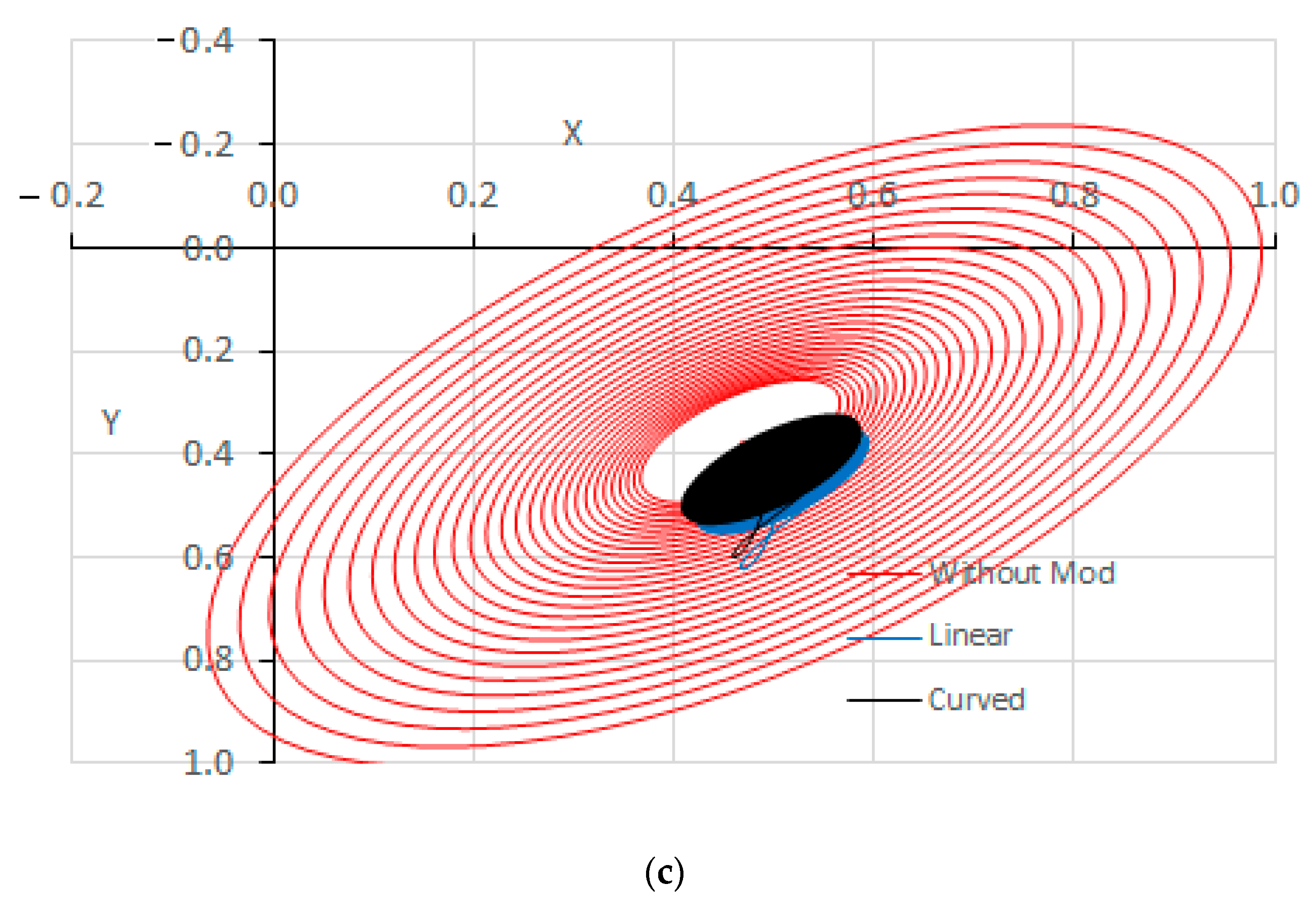
Figure 12c shows the trajectories when the system operates at a speed greater than the critical speed of the aligned bearing. It can be seen that the amplitude of the shaft center in the case of the aligned bearing increases with time until the journal hits the bearing, which represents a dangerous situation. The modified bearings in both forms lead to stable operation where the shaft center returns to the original position before applying the impact load. It can be concluded from the results illustrated in this figure that both forms of chamfer lead to a more stable trajectory for the shaft center, which represents an additional advantage for the bearing modification. In addition, the curved chamfer exhibits behavior closer to that of the perfectly aligned bearing under impact load. It is worth mentioning that the trajectory of chamfered misaligned bearings is a relatively complicated problem as the shaft is no longer parallel to the bearing longitudinal axis (bearing width) as a result of the misalignment. In such cases, a 3D trajectory solution is required to trace the path of the shaft “axis” under impact load. The authors intend to solve this problem in future work.
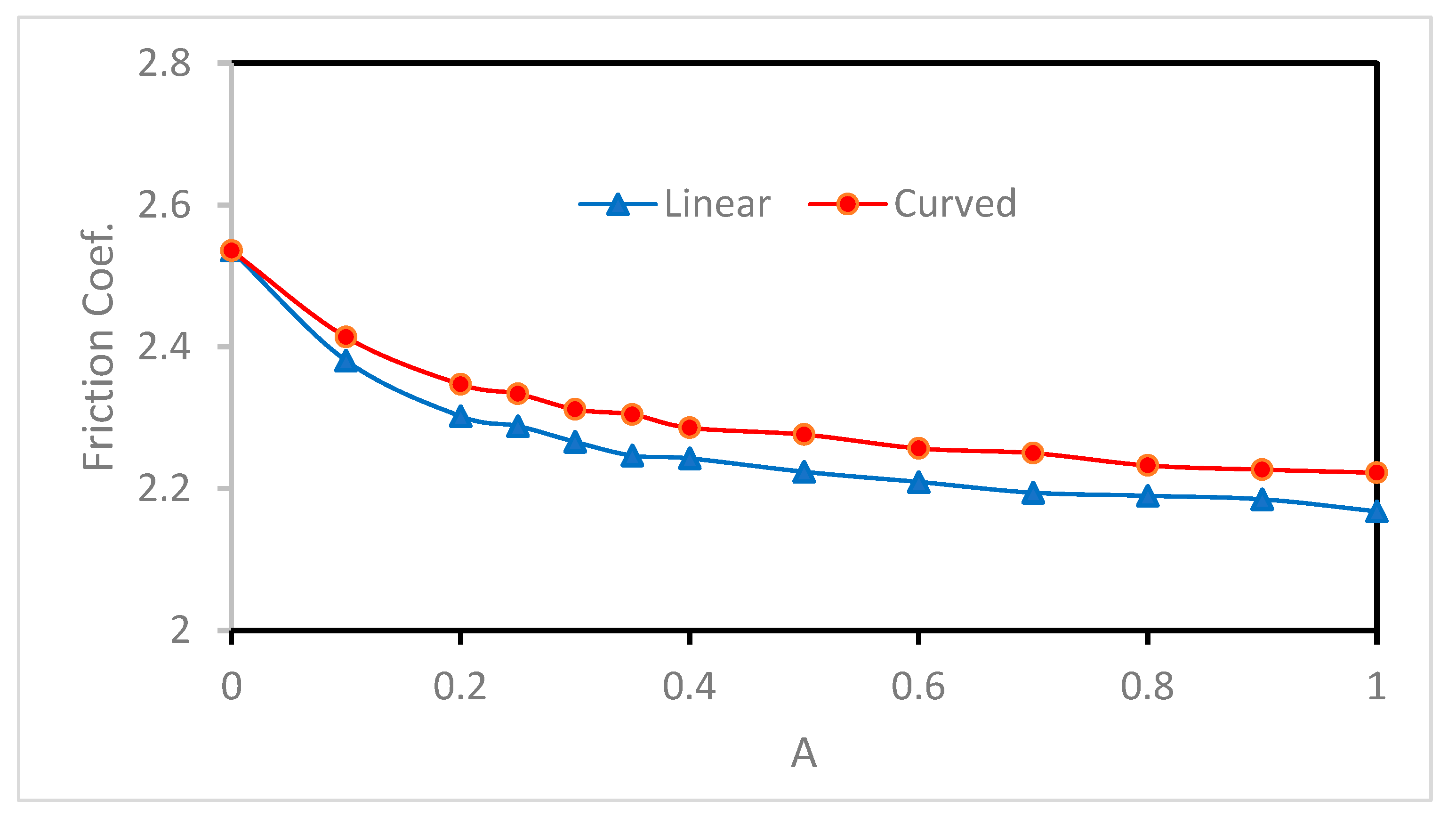
The chamfer effects on the coefficient of friction are shown in Figure 13. The severe level of misalignment considered in this work leads to an increase in the coefficient of friction by 14.3% (from 2.218 to 2.536). Introducing the two forms of chamfer reduces the coefficient of friction for all values of A, which is also a significant step in the right direction. The results related to the effects of the chamfer on Pmax and Hmin showed that the optimum value of A was 0.25. The corresponding reductions in the coefficient of friction in comparison with the misaligned case at this value of parameter A are 9.7% and 8.0% for the linear and curved chamfer, respectively.

10. Conclusions

This paper presented a novel general solution for the modified finite-length journal bearing considering a 3D misalignment model. The modification of the bearing profile consisted of two forms: linear and curved chamfers. The numerical solution was based on the finite difference method considering the Reynolds boundary condition method to identify the cavitation zone. The analysis was used to assess the dynamic characteristics of the modified bearing in addition to the coefficient of friction. Furthermore, the trajectory of the bearing under the two forms of the chamfer was also determined by solving the equations of motion using the fourth-order Runge-Kutta method. Results showed that modifying the bearing profile using any of the two forms helped minimize the misalignment effects by reducing the maximum pressure and elevating the reduced film thickness level associated with misalignment. The coefficient of friction was also reduced by the linear and curved chamfers. The critical speed was improved as a result of the modification in comparison with the perfectly aligned case. Furthermore, examining the journal trajectories under impact load showed that the chamfered bearing led to a more stable path for the journal. It has been found that the optimum chamfer parameters are B = 0.25 and 0.2 < A < 0.4 for both forms of chamfer. However, the curved modification is preferable as it keeps improving the system performance over a wider range of chamfer parameters.

Author Contributions

Formal analysis, Investigation, Writing -review and editing, H.U.J.; Methodology, Resources, H.S.S.; Formal analysis, Writing—review and editing, O.I.A.; Resources, Funding Acquisition, A.N.J.A.-T.; Validation, Writing—review and editing, L.H.A.; Writing -review and editing, Supervision, A.R.; Writing -review and editing, Z.A.A.-D. All authors have read and agreed to the published version of the manuscript.

Funding

This research received no external funding.

Institutional Review Board Statement

Not applicable.

Informed Consent Statement

Not applicable.

Data Availability Statement

The study did not report any data.

Conflicts of Interest

The authors declare no conflict of interest.

References

  1. Ribeiro, E.A.; Alves, D.S.; Cavalca, K.L.; Bavastri, C.A. Stability analysis and optimization of a hybrid rotating machinery support combining journal bearings with viscoelastic supports. Mech. Mach. Theory 2021, 156, 104166. [Google Scholar] [CrossRef]
  2. Hashimoto, H. Optimization of oil flow fate and oil film temperature rise in high speed hydrodynamic journal bearings. Tribol. Ser. 1998, 34, 205–210. [Google Scholar]
  3. Muszynska, A. Stability of whirl and whip in rotor/bearing systems. J. Sound Vib. 1988, 127, 49–64. [Google Scholar] [CrossRef]
  4. Lund, J.W.; Thomsen, K.K. A Calculation Method and Data for the Dynamic Coefficients of Oil-Lubricated Journal Bearings. In Topics in Fluid Film Bearing and Rotor Bearing System Design and Optimization; ASME: New York, NY, USA, 1978. [Google Scholar]
  5. Chang, C.; Zheng, P. Experimental Determination of the Stiff- ness and Damping Coefficients of Fluid Film Bearings by Means of Step Forces. Tribol. Int. 1985, 18, 81–91. [Google Scholar] [CrossRef]
  6. Subbiah, R.; Bhat, R.B.; Sankar, T.S. Rotational Stiffness and Damping Coefficients of Fluid Film in a Finite Cylindrical Bearing. ASLE Trans. 1985, 29, 414–422. [Google Scholar] [CrossRef]
  7. Klit, P.; Lund, J.W. Calculation of the Dynamic Coefficients of a Journal Bearing Using a Variational Approach. J. Tribol. 1986, 108, 421–425. [Google Scholar] [CrossRef]
  8. Nefske, D.J.; Sung, S.H. Coupled Vibration Response of the Engine Crank-Block System. ASME Publ. DE 1989, 18, 379–385. [Google Scholar]
  9. Lund, J.W. Review of the Concept of Dynamic Coefficients for Fluid Film Journal Bearings. J. Tribol. 1987, 109, 37–41. [Google Scholar] [CrossRef]
  10. Kostrzewsky, G.J.; Flack, R.D. Accuracy Evaluation of Experimentally Derived Dynamic Coefficients of Fluid Film Bearings. Part I: Development of Method. Tribol. Trans. 1990, 33, 105–114. [Google Scholar] [CrossRef]
  11. Ruggiero, A.; D’Amato, R.; Magliano, E.; Kozak, D. Dynamical Simulations of a Flexible Rotor in Cylindrical Uncavitated and Cavitated Lubricated Journal Bearings. Lubricants 2018, 6, 40. [Google Scholar] [CrossRef]
  12. Frene, J. Hydrodynamic Lubrication Bearings and Thrust Bearings; Elsevier: Amsterdam, The Netherlands, 1997. [Google Scholar]
  13. Sun, J.; Gui, C.; Li, Z.; Li, Z. Influence of Journal Misalignment Caused by Shaft Deformation Under Rotational Load on Performance of Journal Bearing. Proc. Inst. Mech. Eng. Part J J. Eng. Tribol. 2005, 219, 275–283. [Google Scholar] [CrossRef]
  14. Rao, T.V. Stability Characteristics of Misaligned Journal Bearing. Adv. Vib. Eng. 2012, 11, 362–369. [Google Scholar]
  15. Nacy, S.M. Effect of Chamfering on Side-Leakage Flow Rate of Journal Bearings. Wear 1997, 212, 95–102. [Google Scholar] [CrossRef]
  16. Bouyer, J.; Fillon, M. Improvement of the THD Performance of a Misaligned Plain Journal Bearing. J. Tribol. 2003, 125, 334–342. [Google Scholar] [CrossRef]
  17. Strzelecki, S. Operating Characteristics of Heavy Loaded Cylindrical Journal Bearing with Variable Axial Profile. Mater. Res. 2005, 8, 481–486. [Google Scholar] [CrossRef]
  18. Chasalevris, A.; Dohnal, F. A journal bearing with variable geometry for the suppression of vibrations in rotating shafts: Simulation, design, construction and experiment. Mech. Syst. Signal Process. 2015, 52–53, 506–528. [Google Scholar] [CrossRef]
  19. Chasalevris, A.; Dohnal, F. Enhancing Stability of Industrial Turbines Using Adjustable Partial Arc Bearings. J. Phys. 2016, 744, 012152. [Google Scholar] [CrossRef]
  20. Liu, C.; Zhao, B.; Li, W.; Lu, X. Effects of bushing profiles on the elastohydrodynamic lubrication performance of the journal bearing under steady operating conditions. Mech. Ind. 2019, 20, 207. [Google Scholar] [CrossRef]
  21. Jamali, H.U.; Sultan, H.S.; Senatore, A.; Al-Dujaili, Z.A.; Jweeg, M.J.; Abed, A.M.; Abdullah, O.I. Minimizing Misalignment Effects in Finite Length Journal Bearings. Designs 2022, 6, 85. [Google Scholar] [CrossRef]
  22. Qiu, Z.L.; Tieu, A.K. Misalignment effect on the static and dynamic characteristics of hydrodynamic journal bearings. J. Tribol. 1995, 117, 717–723. [Google Scholar] [CrossRef]
  23. Tieu, A.K.; Qiu, Z.L. Stability of Finite Journal Bearings -from Linear and Nonlinear Bearing Forces. Tribol. Trans. 1995, 38, 627–635. [Google Scholar] [CrossRef]
  24. Abass, A.; Mohammed, M. The Effect of Surface Roughness on Thermohydrodynamic Performance in Misaligned Journal Bearings. Al-Khwarizmi Eng. J. 2010, 6, 61–76. [Google Scholar]
  25. Papadopoulos, C.A.; Nikolakopoulos, P.G.; Gounaris, G.D. Identification of clearances and stability analysis for a rotor-journal bearing system. Mech. Mach. Theory 2008, 43, 411–426. [Google Scholar] [CrossRef]
  26. Boukhelef, D.; Bounif, A.; Bouzid, D.A. Dynamic characterization and stability analysis of hydrodynamic journal bearing using the FEM. Mechanics 2011, 17, 503–509. [Google Scholar] [CrossRef]
  27. Nicoletti, R. Optimization of journal bearing profile for higher dynamic stability limits. J. Tribol. 2013, 135, 011702. [Google Scholar] [CrossRef]
  28. Mehrjardi, M.Z.; Rahmatabadi, A.D.; Meybodi, R.R. A comparative study of the preload effects on the stability performance of noncircular journal bearings using linear and nonlinear dynamic approaches. Proc. Inst. Mech. Eng. Part J J. Eng. Tribol. 2016, 230, 797–816. [Google Scholar] [CrossRef]
  29. Yadav, S.K.; Rajput, A.K.; Ram, N.; Sharma, S.C. Stability analysis of a rigid rotor supported by two-lobe hydrodynamic journal bearings operating with a non-Newtonian lubricant. Proc. Inst. Mech. Eng. Part J J. Eng. Tribol. 2019, 233, 884–898. [Google Scholar] [CrossRef]
  30. Dyk, S.; Rendl, J.; Byrtus, M.; Smolik, L. Dynamic Coefficients and Stability Analysis of Finite-Length Journal Bearings Considering Approximate Analytical Solutions of the Reynolds Equation. Tribol. Int. 2018, 130, 229–244. [Google Scholar] [CrossRef]
  31. Sun, F.; Zhang, X.; Wang, X.; Su, Z.; Wang, D. Effects of shaft shape errors on the dynamic characteristics of a rotor-bearing system. J. Tribol. 2019, 141, 101701. [Google Scholar] [CrossRef]
  32. Zhang, J.; Zhao, H.; Zou, D.; Ta, N.; Rao, Z. Comparison study of misalignment effect along two perpendicular directions on the stability of rigid rotor-aerostatic journal bearing system. Proc. Inst. Mech. Eng. Part J J. Eng. Tribol. 2020, 234, 1618–1634. [Google Scholar] [CrossRef]
  33. Li, B.; Zhou, D.; Ogrodnik, B.; Xu, W. Effect of journal cylindricity error with saddle or drum distribution on the performance of hydrodynamic journal bearing systems. Proc. Inst. Mech. Eng. Part J J. Eng. Tribol. 2020, 234, 1092–1105. [Google Scholar] [CrossRef]
  34. Jamali, H.U.; Sultan, H.S.; Abdullah, O.I.; Al-Tamimi, A.N.J.; Albdeiri, M.S.; Ruggiero, A.; Al-Dujaili, Z.A. Analysis of the Performance of Chamfered Finite-Length Journal Bearings under Dynamic Loads. Mathematics 2023, 11, 587. [Google Scholar] [CrossRef]
  35. Jamil, A.; Ali, A.; Mohammed, T. Study the Dynamic Behavior of Rotor Supported on a Worn Journal Bearings. J. Eng. 2015, 21, 1–18. [Google Scholar]
  36. Jameel, A.; Ali, A.; Mohammad, T. Dynamic Stability Analysis and Critical Speed of Rotor supported by a Worn Fluid film Journal Bearings. J. Eng. 2016, 22, 148–167. [Google Scholar]
  37. Muskat, M.; Morgan, F. Studies in lubrication V. The theory of the thick film lubrication of flooded journal bearings and bearings with circumferential grooves. J. Appl. Phys. 1939, 10, 398–407. [Google Scholar] [CrossRef]
  38. Dufrane, K.F.; Kannel, J.W.; McCloskey, T.H. Wear of steam turbine journal bearings at low operating speeds. J. Lubr. Technol. 1983, 105, 313–317. [Google Scholar] [CrossRef]
  39. Jamali, H.; Al-Hamood, A. A New Method for the Analysis of Misaligned. J. Bear. Tribol. Ind. 2018, 40, 213–224. [Google Scholar] [CrossRef]
  40. Chasalevris, A.; Sfyris, D. Evaluation of the Finite Journal Bearing Characteristics, Using the Exact Analytical Solution of the Reynolds Equation. Tribol. Int. 2013, 57, 216–234. [Google Scholar] [CrossRef]
  41. Hamrock, B.J. Fundamentals of Fluid Film Lubrication; McGraw-Hill, Inc.: New York, NY, USA, 1991. [Google Scholar]
  42. Harnoy, A. Bearing Design in Machinery: Engineering Tribology and Lubrication, 1st ed.; Marcel Dekker Inc.: New York, NY, USA, 2002. [Google Scholar]
  43. Feng, H.; Jiang, S.; Ji, A. Investigation of the Static and Dynamic Characteristics of Water-Lubricated Hydrodynamic Journal Bearing Considering Turbulent, Thermo-hydrodynamic and Misaligned Effects. Tribol. Int. 2019, 130, 245–260. [Google Scholar] [CrossRef]
  44. Someya, T. Journal Bearing Databook; Springer: Berlin/Heidelberg, Germany, 1989. [Google Scholar]
  45. D’Amato, R.; Amato, G.; Wang, C.; Ruggiero, A. A Novel Tracking Control Strategy with Adaptive Noise Cancellation for Flexible Rotor Trajectories in Lubricated Bearings. IEEE/ASME Trans. Mechatron. 2021, 27, 753–765. [Google Scholar] [CrossRef]
  46. Amato, G.; D’Amato, R.; Ruggiero, A. Adaptive Rejection of a Sinusoidal Disturbance with Unknown Frequency in a Flexible Rotor with Lubricated Journal Bearings. Mathematics 2022, 10, 1703. [Google Scholar] [CrossRef]
  47. Ruggiero, A.; Hloch, S.; Kozak, D.; Valasek, P. Analytical fluid film force calculation in the case of short bearing with a fully developedturbulent flow. Proc. Inst. Mech. Eng. Part J J. Eng. Tribol. 2016, 230, 395–401. [Google Scholar] [CrossRef]
Figure 1. Journal bearing geometry. (a) Two-dimensional aligned journal bearing (side view); (b) 3D perfectly aligned journal bearing; and (c) the adopted misalignment model [38].
Lubricants 11 00073 g001
Figure 2. Chamfer geometry. Left: linear and right: curved chamfer. (a) Three-dimensional unmodified bearing; (b) 3D section for the modification; (c) schematic drawing of the chamfered bearing.
Lubricants 11 00073 g002aLubricants 11 00073 g002b
Figure 3. Schematic drawing of (a) side and front views of the system and (b) journal movement [23].
Lubricants 11 00073 g003
Figure 4. Flow chart of the solution steps.
Lubricants 11 00073 g004
Figure 5. Effect of number of nodes on (a) Pmax and Hmin and (b) friction coef. and critical speed.
Lubricants 11 00073 g005
Figure 6. Pressure distribution and film thickness. Left: aligned and right: misaligned. (a,b) Three-dimensional pressure distribution; (c,d) 2D film thickness.
Lubricants 11 00073 g006aLubricants 11 00073 g006b
Figure 7. Three-dimensional pressure distribution for misaligned and chamfered bearing L / D = 1.25 ,   B = 0.25 . Left: curved chamfer and right: linear chamfer. (a) A = 0.1, (b) A = 0.25, (c) A = 0.5, (d) A = 0.7, (e) A = 1.
Lubricants 11 00073 g007aLubricants 11 00073 g007b
Figure 8. Two-dimensional film thickness contours for misaligned and chamfered bearing L / D = 1.25 ,     B = 0.25 . Left: curved chamfer and right: linear chamfer. (a) A = 0.1, (b) A = 0.25, (c) A = 0.5, (d) A = 0.7, (e) A = 1.
Lubricants 11 00073 g008aLubricants 11 00073 g008b
Figure 9. Effect of chamfer parameter A on: (a) Pmax and CS and (b) Hmin (L/D = 1.25 and B = 0.25).
Lubricants 11 00073 g009
Figure 10. Effect of chamfer form on (a) stiffness coefficients and (b) damping coefficients when A = B = 0.25 .
Lubricants 11 00073 g010
Figure 11. Effect of chamfer form on (a) stiffness coefficients and (b) damping coefficients when A = 0.7   and   B = 0.25 .
Lubricants 11 00073 g011
Figure 12. Trajectories of the shaft center under impact load when the operating speed is: (a) less than, (b) equal to, or (c) greater than the critical speed of the aligned bearing.
Lubricants 11 00073 g012aLubricants 11 00073 g012b
Figure 13. Effect of chamfer form on the coefficient of friction (B = 0.25), f = 2.218 for aligned case.
Lubricants 11 00073 g013
Table 1. Comparison between the dimensionless critical speeds obtained in the current work and the corresponding values for reference [4]   L / D = 0.5 .
ε r Critical Speed% Difference
Current WorkLund and Thomson
0.1652.3612.3710.442
0.2442.3482.3530.213
0.4772.2992.3050.254
0.6552.6252.6440.722
0.7343.4783.6023.445
0.7614.3824.4962.540
Table 2. Effect of misalignment on the main characteristics when Δ h = Δ v = 0.58 .
CaseAlignedMisaligned% Change
Pmax0.6444580.97809051.77
Hmin0.4000000.006606−98.35
CS2.6789703.91897846.28
Table 3. Effect of misalignment and chamfer form on Pmax, Hmin, and CS when A = 0.5 and A = 0.7 .
CaseAlignedMisaligned% ChangeA = 0.25A = 0.7
LinearCurvedLinearCurved
Pmax0.6444580.97809051.770.72040.73171.00880.8506
Hmin0.4000000.006606−98.350.25410.24060.18840.2241
CS2.6789703.91897846.283.40203.40293.80203.4279
Disclaimer/Publisher’s Note: The statements, opinions and data contained in all publications are solely those of the individual author(s) and contributor(s) and not of MDPI and/or the editor(s). MDPI and/or the editor(s) disclaim responsibility for any injury to people or property resulting from any ideas, methods, instructions or products referred to in the content.

