Article

Anti-Wear Design of the Knot-Tripping Mechanism and Knot-Tying Test for the Knotter

School of Agricultural Engineering, Jiangsu University, Zhenjiang 212013, China
*
Author to whom correspondence should be addressed.
Lubricants 2023, 11(11), 475; https://doi.org/10.3390/lubricants11110475
Submission received: 2 September 2023 / Revised: 31 October 2023 / Accepted: 1 November 2023 / Published: 4 November 2023

Abstract

:
Aiming to solve the problem of knot-tripping failure caused by severe wear between the spherical roller and planar cam of the knotter, this paper first establishes a calculation model of the spatial cam contour surface. The knot-tripping mechanism in the knotter is designed as a line-contact curved-surface cam mechanism, with the cutter arm swinging in accordance with sinusoidal acceleration. The design significantly reduces the contact stress between the cam and the roller, compared to the original knot-tripping mechanism. Additionally, it eliminates the impact between the spherical roller and the planar cam. Based on the Archard model, the calculation model for cam-roller wear in the knot-tripping mechanism has been derived and utilized for wear calculation. The wear test results of the knot-tripping mechanism with an aluminum cam show that the curved cam has a wear amount that is 43%, 56%, 46%, and 37% lower than that of the planar cam after tying the knot 200 times, 600 times, 1300 times, and 2000 times, respectively. Under the condition that the twine tension is set to 120 N, and the rotation speed of the fluted disc is 60 rpm, the deviations between the calculated value and the measured value of the wear amount of the curved cam are 9.48%, 6.01%, 7.27%, and 9.95%, respectively. This validates the accuracy of the spatial cam wear model and the correctness of the curved cam design.

1. Introduction

At present, approximately 2 billion tons of straw are produced worldwide each year [1]. Due to the low utilization rate of straw, the environmental problems caused by straw burning are significant. With the advancement of bioenergy technology, straw has been recognized as a renewable biomass resource, while it was previously considered as agricultural waste [2,3]. The equipment and technology for collecting, storing, and transporting straw have become bottlenecks to effective utilization. The promotion and use of a baling machine provide an effective method for the rapid recovery of straw. Now, the research on square balers mainly focuses on improving bale density [4,5,6] and optimizing efficiency [7,8,9].
The complex structure of the knotter, which is the central component of the baler, requires the accurate meshing of the tooth disks for efficient transmission during operation. Additionally, the mechanisms for knot-winding and rope-tripping must be coordinated with precise timing requirements. To improve the reliability of the knotter’s knotting process, studying the structural parameters and analyzing the motion of the knotter can enable the parametric modeling of the knotter structure and facilitate structural optimization analysis. Based on the Adams (Automatic Dynamic Analysis of Mechanical Systems) motion simulation software, Yin et al., 2011 [10] conducted correlation studies on the timing relationship of the knotter construction coupling action. They also conducted studies on the spatial component parameters, which provide a basis for parameterizing the structure of the knotter. Zhang et al., 2018 [11] conducted a motion analysis of the knotter components using differential geometry theory to ensure that the knotter can achieve a reliable knotting action.
The rope-tripping mechanism is one of the key components of the D-type knotter rope-cutter. It consists of a spherical roller and a rope-tripping mechanism with a cam contact point. However, there are several issues associated with this mechanism, including high-impact loads, stress concentration, and severe wear. Under prolonged use, it can affect the sequential coordination of the knotter’s work and result in knotting failures. In order to address the problem of the rigid impact caused by the rope-tripping mechanism, Xiong et al., 2016 [12] devised an elastic knotting nozzle based on the principles of rigid-flexible collision theory. This design reduces the initial contact stress of the knotter rope-tripping mechanism and minimizes wear. To address the issue of severe wear on the inner contour of the cam in the knotter’s rope-tripping mechanism, Li et al., 2015 [13] proposed a solution. They suggested replacing the column surface contour with an equidistant circular arc surface that matches the theoretical contour surface of the cam. This modification increases the initial contact area between the roller and the cam, reduces the maximum initial contact stress, and alleviates wear on the inner contour of the cam.
In addition, improving the density of knotting and exploring new structures are also important research areas for knotters. The Loop MasterTM, a circular knotter designed and researched by New Holland, has achieved both “loop” and double knotting [14]. The design of the Loop MasterTM reduces the waste of the rope end and increases the tensile strength of the rope by 26%, thereby reducing the need for high-quality rope. The new V-shaped knotter launched by the KRONE company combines the high operational reliability of a dual-knotter with the non-chipping Cormick single-knotter [15]. It replaces the cutting mechanism with a yarn extractor, which reduces the rope debris of the knotter and improves the efficiency of the knot formation.
In recent years, numerical simulation technology has been gradually applied to tribology systems. Due to the complexity of wear mechanisms, scholars have established various wear models, among which the Archard wear model is the most widely used. Osman et al. [16,17] conducted quasi-static and dynamic simulations of gears based on Archard’s wear law and used a time-step integration scheme combined with a contact algorithm to solve the gear motion equation. JanaKiraman et al. [18,19] combined the Hertz contact theory with the Archard wear equation to establish a point contact wear model and conducted numerical simulations. Thus, the regression equation for estimating the Archard wear coefficient has been obtained, providing an important reference for the numerical simulation of gear tooth surface wear. Liu et al. [20] modified the Archard equation to account for elastic/pseudo-elastic properties and used the modified wear equation to predict and experiment with the wear of several engineering materials. The results showed that the modified wear equation had a good predictive performance for high elastic/pseudo-elastic materials.
At present, the research on the knotter mechanism primarily focuses on improving the reliability, optimizing the structure, and increasing knot density. However, the theoretical analysis of knotter wear has been neglected. This article theoretically studies the phenomenon and mechanism of wear in the knotting mechanism. A wear prediction model was established based on the theory of Archard, and a scheme was proposed to reduce wear by replacing the existing planar cam profile with a linear-contact surface cam mechanism containing sinusoidal acceleration. The improved curved cam and the pre-improved planar cam were trial-produced using an aluminum alloy material, and wear experiments were conducted. The experimental results showed good consistency with the predicted model.

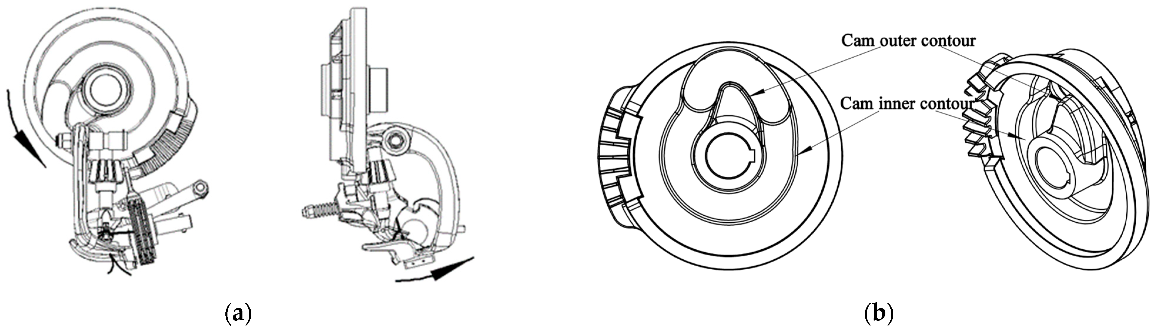
2. Structure and Working Process of the Knot-Tripping Mechanism

As shown in Figure 1, the knot-tripping mechanism is a composite structure that primarily consists of the knotter rack, a planar cam with a groove on the large fluted disk, a cutter arm, and a spherical roller installed at the end of the cutter arm.
As shown in Figure 2a, when the large fluted disk rotates continuously with the drive of the knotter spindle, the planar cam can be considered as a form-closed cam mechanism (as shown in Figure 2b). The contour will drive and control the swinging motion of the cutter arm around its axis. During the swinging motion of the cutter arm, the rope-cutting knife, which is attached to the cutter arm, will complete the cutting action of the rope. The knot-tripping mechanism will then complete the release action. The notch on the cutting arm and the bottom of the knotter jaw are designed as transitional fits, which assist in removing the knotter knot from the knotter jaw.

3. Establishment of the Prediction Model for Cam-Roller Wear

3.1. Establishment of the Calculation Model for Cam Wear

The wear of the knotter is primarily caused by fatigue wear resulting from rolling and sliding when the cam comes into contact with the roller. The cam is a positive-drive cam mechanism, and the internal contour of the cam experiences significant force when driving the cutting arm to complete the knot-tripping motion. This leads to significant wear of the internal contour. The contact section between the roller and the outer contour of the cam primarily consists of the cam’s resting segment. Therefore, there is less friction between the roller and the outer contour of the cam. In this paper, the problem of severe wear of the inner contour is analyzed (note: the term “contour” in the subsequent papers specifically refers to the inner contours only).
However, the current calculation equation for the fatigue wear theory is quite complicated, and many parameters lack an accurate basis [21]. Therefore, there are limitations to its application. This paper aims to modify Archard’s wear theory to predict the differences in wear between the cams and the rollers. The Archard wear theory is formulated as follows [22]:
d V = K d P × d L H
where V is the wear volume; K is the worn coefficient; P is the normal load at the contact point; L is the friction stroke; and H is the Brinell hardness of the material, in which  d V , d P , d L  can be expressed by the following equation:
d V = d h d A ,   d P = σ d A ,   d L = v d t
where h is the wear depth; A is the apparent contact area; v is the relative (slip) velocity; and t is the slip time. Then, Equation (1) can be rewritten as follows:
d h = K v H σ d t
In the Archard theoretical model, the velocity and the contact stress are defined as constants. However, in the cam model, the velocity and the stress at the contact point vary over time. Therefore, in this paper, the Archard model has been modified to the following equation:
d h = K v ( t ) × σ ( t ) H d t
Systematic tables of friction coefficients have been developed based on extensive testing. By using the wear coefficient k for K/H, the wear depth h of the contact point can be expressed as follows [23]:
h = 0 t k v ( t ) σ ( t ) d t
where  v ( t )  is the relative velocity of the contact section and  σ ( t )  is the contact stress.
As shown in Figure 3, the origin O of the space-rectangular coordinate system is the point where the cutter arm rotation axis intersects with the upward projection of the knotter spindle. The direction of the x-axis is determined by the rotation axis of the cutter arm, while the direction of the z-axis is determined by the spindle of the knotter. The coordinates of the center of rotation of the cutter arm are  O 1 ( 0 , y 1 , 0 ) .
In the computational modeling of the cam-roller contact profile, the basic cam profile is discretized into a series of independent contact points so that the effects of each point’s parameters on wear are considered separately over time. Additionally, time is discretized in order to simplify the calculation of Equation (5), due to the complex variation of the cam contact stress [24,25]. Based on the discrete contour contact points, the continuous time is considered as the sum of the short motion cycles (i.e., specific tiny time periods denoted by  δ T ).
The rotation speed of the cam spindle is  ω 1  and the swing speed of the tool arm where the roller is located is  ω 2 . The spatial contour of the cam is divided into m parts by uniformly translating the  x O y  plane along the z-axis direction, and then the segmented cam projection contour line is equally divided into n parts by the  z O y  slice with the rotation angle. Consequently, the spatial contour of the cam can be discretely projected onto points  S ( i , j )  (where “i” denotes the i-th cut of the cam space contour line using  x O y  and “j” denotes the j-th cut of the cam space contour line using  z O y ). The  S ( i , j )  satisfies the cam trajectory equation  F ( t ) , and the spatial coordinates of  S ( i , j )  are  ( x ( i , j ) , y ( i , j ) , z ( i , j ) ) . The position vector of the moving point  S ( i , j )  when two parts are in contact is shown in formula (6):
ρ = x ( i , j ) i + y ( i , j ) j + z ( i , j ) k
where  i j , and  k  are the unit vectors of the coordinate system.
As shown in Figure 4, the relative velocity vector at point S can be expressed as follows:
v S E = v S F + v S C
The velocity vector of the point  S F  can be expressed as follows:
v S F = ω 1 ( t ) y ( i , j ) i + ω 1 ( t ) x ( i , j ) j
The velocity vector of the point  S C  can be expressed as follows:
v S C = ω 2 ( t ) z ( i , j ) j + ω 2 ( t ) ( y 1 y ( i , j ) ) k
When the point  S F  on the roller passes the point  S C  on the cam, the relative sliding velocity vector  v S E  can be expressed as follows:
v S E = v S F + v S C = ω 1 ( t ) y ( i , j ) i + ω 1 ( t ) x ( i , j ) j + ω 2 ( t ) z ( i , j ) j + ω 2 ( t ) ( y 1 y ( i , j ) ) k
According to Formula (5), the wear depth of point S on the cam profile at the  f -th cycle is as follows:
Δ h S f = k 0 δ T v S E ( t ) σ f ( t ) d t
where  v S E ( t )  is the relative sliding velocity, it is assumed that the contact stress  σ f ( t )  at the  f -th cycle does not vary with time within a very small wear cycle  δ T , and the distribution of the Hertz contact stress formula is parabolic, so that the wear increment becomes the following:
Δ h S f = k σ f ( t ) 0 δ T v S E ( t ) d t
The wear occurs only when  σ f ( t ) > 0 , namely when point S is in contact. Moreover, as the wear deepens, the contact between the cam and the roller will change from a point contact to a line contact, and, according to the Hertz stress formula,  σ f ( t )  will gradually decrease.
The depth of the cam accumulated by wear over time can be expressed as follows:
h s = f = 1 R Δ h S = k f = 1 R [ σ f ( t ) 0 δ T v S E ( t ) d t ]

3.2. Replacement of Worn Cam Profile

The wear vector during a wear cycle is always in the direction normal to the friction surface, which is the direction of the line between the contact point and the cam center of rotation. However, after being worn, the direction of the wear vector changes in accordance with the wear pattern of the surface. Therefore, the direction of the wear vector must be determined as follows:
The direction of the wear vector is perpendicular to the line connecting the adjacent contact points on the cam profile. Then, the direction of the wear vector for the  f -th wear cycle can be expressed as the angle with the unit coordinate vector, as follows:
α f y , ( i , j ) = a c r t g ( y f , ( i , j ) y f , ( i , j 1 ) ) ( x f , ( i , j ) x f , ( i , j 1 ) )
α f z , ( i , j ) = a c r t g ( z f , ( i , j ) z f , ( i 1 , j ) ) ( y f , ( i , j ) y f , ( i 1 , j ) )
α f x , ( i , j ) = a c r t g ( x f , ( i , j ) x f , ( i 1 , j 1 ) ) ( z f , ( i , j ) z f , ( i 1 , j 1 ) )
where  α f x , ( i , j ) α f y , ( i , j ) , and  α f z , ( i , j )  are the angles to the unit vectors  i j ,and  k , respectively.
( x f , ( i , j ) , y f , ( i , j ) , z f , ( i , j ) )  is the cam profile coordinate of point  S ( i , j )  at the  f -th wear cycle. After one wear cycle, the coordinates of the profile  S f + 1 , ( i , j )  after  f + 1  cycles can be found as follows:
x f + 1 , ( i , j ) = x f , ( i , j ) + Δ h S f cos α f x , ( i , j )
y f + 1 , ( i , j ) = y f , ( i , j ) + Δ h S f cos α f y , ( i , j )
z f + 1 , ( i , j ) = z f , ( i , j ) + Δ h S f cos α f z , ( i , j )

4. Design of the Knot-Tripping Mechanism with the Curved Cam

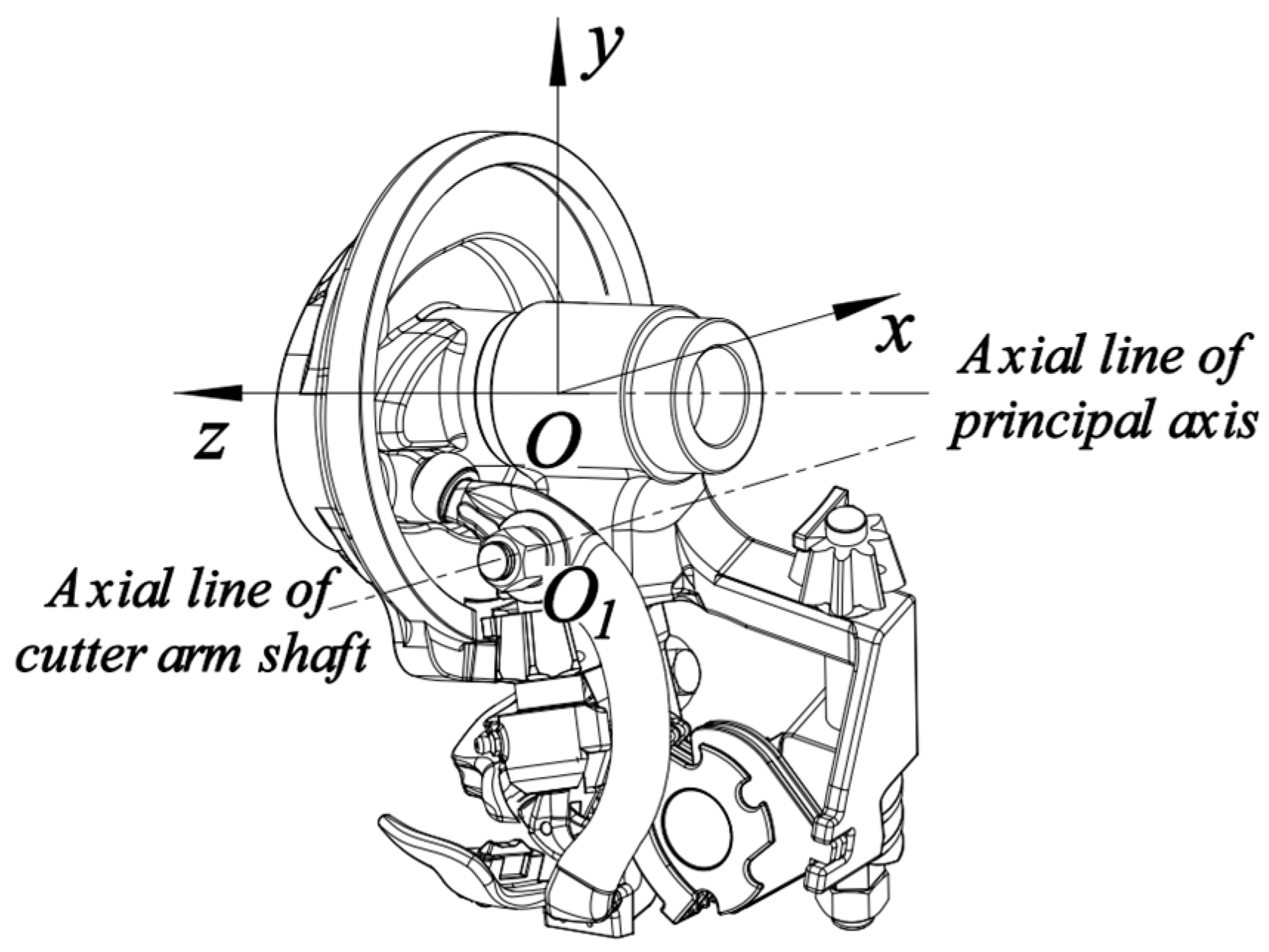
4.1. Establishment of the Coordinate System of the Roller Motion

In order to obtain the space coordinate formula of the center point P on the surface of the roller at any time, the fixed coordinate system  δ ( O x y z )  and the moving coordinate system  δ 1 ( O 1 x 1 y 1 z 1 )  are, respectively, established on the principal axis of the knotter holder and the axis of the cutter arm, as shown in Figure 5. The moving coordinate system  δ 1  is obtained by translating the fixed coordinate system  δ  and rotating the angle  β  around the x-axis of the original fixed coordinate system. The center  O 1  of the moving coordinate system  δ 1  is the intersection point obtained from the perpendicular line made from point P towards the axis  m n  of the cutter arm. The  z 1  axis coincides with the axial line of the cutter arm shaft. The translation length of  O 1  relative to point O in the negative direction of the  y  axis is  l y , and the translation length of  O 1  relative to point O in the positive direction of the  z  axis is  l z . Point Q is the center of the lower surface of the roller.
According to the rigid body translation and the rotation transformation rules, the coordinate transformation relationship between the fixed coordinate system  δ  and the moving coordinate system  δ 1  is expressed as follows:
[ x y z 1 ] = [ 1 0 0 0 0 cos β sin β 0 0 sin β cos β 0 0 0 0 1 ] [ 1 0 0 0 0 1 0 l y 0 0 1 l z 0 0 0 1 ] [ x 1 y 1 z 1 1 ]

4.2. Establishment of Theoretical Contour Equation for Curved Cam

As shown in Figure 6, in the moving coordinate system  δ 1 , the trajectory of point P is an arc in the plane  x 1 O 1 y 1  and its coordinate is  ( x 0 , y 0 , 0 ) . The distance from the center  P 0  of the roller to the origin center  O 1  is indicated by the symbol of L. The distance from point P to point Q is  L f , and the initial angle between  O 1 P 0  and the  x 1  axis is  θ 0 .
By substituting  P ( x 0 , y 0 , 0 )  into Formula (20), the parameter formula of the spatial trajectory of point P in the fixed coordinate system  δ  can be obtained as follows:
[ x y z 1 ] = [ x 0 ( y 0 + l y ) cos β l z sin β ( y 0 l y ) sin β l z cos β 1 ]
where  0 β 360 ° . With the rotation of the cam, the cutting arm oscillates in accordance with the sinusoidal acceleration law during the pushing stage and the returning stage of the cam. The pushing stage corresponds to the  P 0 P 1  section and the return section corresponds to the  P 1 P 0  section in Figure 6. The coordinates of point P at the upper end of the roller in the moving coordinate system  δ 1  are expressed as follows:
{ x p = L cos ( θ 0 θ ) y p = L sin ( θ 0 θ ) z p = 0
The coordinates of the center Q point at the lower end of the roller in the moving coordinate system  δ 1  are expressed as follows:
{ x Q = ( L L f ) cos ( θ 0 θ ) y Q = ( L L f ) sin ( θ 0 θ ) z Q = 0
In order to minimize the impact of the roller and the curved cam, the swinging motion of the cutter arm is designed based on the sine acceleration law [26]. Additionally, the contour of the curved cam is designed according to the trajectory of points P and Q. By substituting Formula (22) and (23) into Formula (21), the spatial coordinates of point P and point Q in the fixed coordinate system  δ  can be obtained as follows:
[ x P y P z P 1 ] = [ L cos ( θ 0 θ ) L sin ( θ 0 θ ) cos β + l y cos β l z sin β L sin ( θ 0 θ ) sin β l y sin β l z cos β 1 ]
[ x Q y Q z Q 1 ] = [ ( L L f ) cos ( θ 0 θ ) ( L L f ) sin ( θ 0 θ ) cos β + l y cos β l z sin β ( L L f ) sin ( θ 0 θ ) sin β l y sin β l z cos β 1 ]
By referring to the structural parameters of the D-type knotters manufactured by the Rasspe Company in Germany, the corresponding structural parameters for the curved cam are as follows: the value of  L , L f , a , b , and  θ 0  are 64 mm, 17 mm, 58 mm, 22 mm, and 29°, respectively. The space surface formed by the spatial motion path of points P and Q obtained by Formulas (24) and (25) is the theoretical contour surface of the cam. By calculation, the theoretical profile surface of the linear-contact curved cam is shown in Figure 7; its 3D model, along with the actual profile surface, is shown in Figure 8a; and the manufactured prototype of the curved cam is shown in Figure 8b. In addition, the rollers that fit the cams are modified accordingly, as shown in Figure 8c.

4.3. The Comparison of Mechanical Properties between the Knot-Tripping Mechanism with Planar Cam and the Knot-Tripping Mechanism with Curved Cam

4.3.1. The Comparison of Pressure Angle of the Knot-Tripping Mechanism

The pressure angle curves of the knot-tripping mechanism can be calculated for both the planar cam and the curved cam. These curves are shown in Figure 9. The results show that the pressure angle of the knot-tripping mechanism with the curved cam is reduced by approximately 30% at the beginning section of the pushing stage of the cam. Additionally, the maximum pressure angle of the knot-tripping mechanism with the planar cam has decreased by approximately 20 degrees.

4.3.2. The Comparison of Cam-Roller Contact Force

The virtual knotting method under the Adams View 2020 software can be used to simulate the knotting process of the knotter, and the dynamics and kinematics data from each part can be obtained [27,28,29]. As shown in Figure 10, two types of virtual prototypes for the knotter test device with the planar cam and the curved cam are established, respectively. The material of the cams was set to an aluminum alloy, and the dynamics simulations of the knotter are carried out by using the Adams solver.
At the end of the simulation, the contact force data between the planar cam and the spherical roller are exported and are shown by the red line in Figure 11. Similarly, the contact force data between the curved cam and the cylindrical roller are shown by the blue line in Figure 11.
When the rotational speed of the principal axis of the knotter is set to 60 rpm, the contact force between the curved cam and the cylindrical roller is significantly lower than that of the contact force between the planar cam and the spherical roller in the knot-tripping mechanism. According to the simulation results, the maximum contact force between the planar cam and the spherical roller is approximately 1889 N when the cutter arm contacts the knotter jaw and finally takes off the knot. The maximum contact force between the curved cam and the cylindrical roller is approximately 605 N, which is reduced by 68% compared to the maximum contact force between the planar cam and the spherical roller.

5. Calculation Results and Test Verification of the Knot-Tripping Mechanism

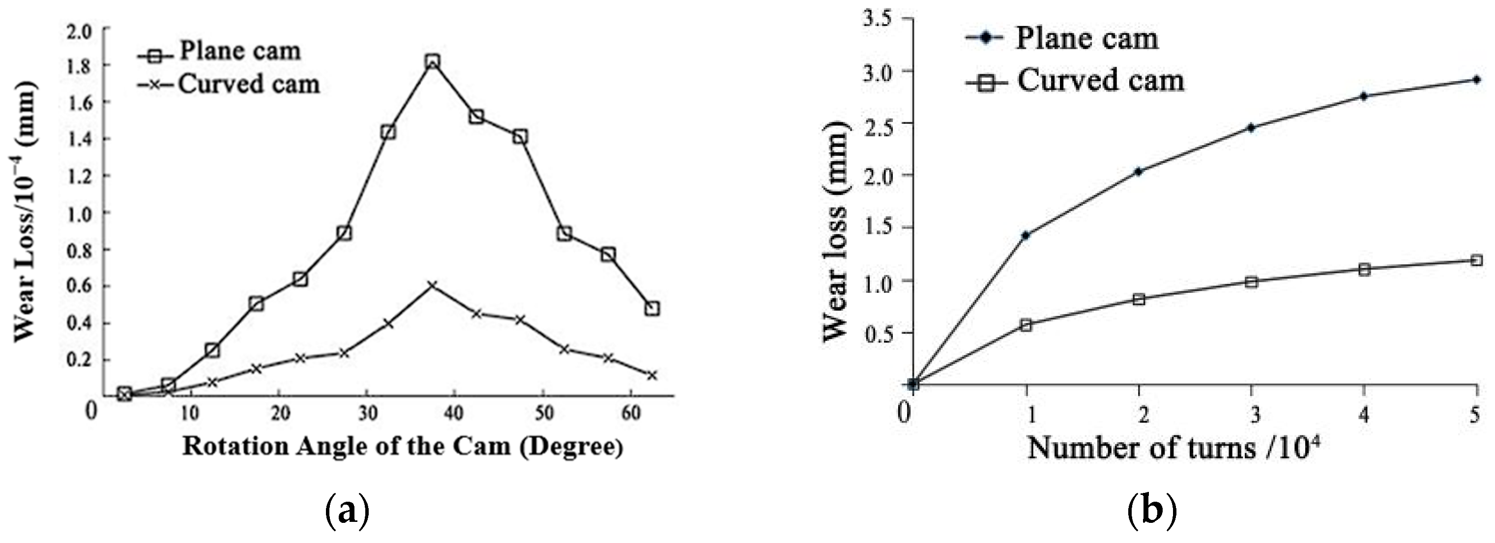
5.1. The Calculation Results of the Wear Model and Wear Test

According to the wear coefficient measured by the Rabinowicz test [30], the wear coefficient (k) is  1 × 10 11   mm 3 · N 1 · m 1  when the Brinell hardness of the aluminum alloy material is 50 HB. By utilizing MATLAB R2022b software, the amount of wear on two different types of cam release mechanisms was calculated after a single operation cycle. The resulting wear loss diagram in the cam lifting section is depicted in Figure 12.
In order to quantitatively compare the wear of the planar cam knot-tripping mechanism with that of the curved cam knot-tripping mechanism, two types of cams were manufactured using aluminum alloy 6061, as shown in Figure 13. In order to manufacture the curved cam knot-tripping mechanism conveniently, the split-type processing method was adopted. The split fluted disk with a curved cam is shown in Figure 14.
The two knot-tripping mechanisms were installed on the test bench of the knotter, as shown in Figure 15. In order to simulate the actual conditions of the knot testing, the rope tension was set to 120 N, the spindle speed was set to 60 rpm, and the test bench was used for continuous knot testing. A total of 2000 knots were made by using two types of knot-tripping mechanisms in the test, as shown in Figure 16.
In order to accurately compare the wear of the planar cam knot-tripping mechanism and the curved cam knot-tripping mechanism, a handheld self-positioning 3D scanner with an accuracy of 0.02 mm was used to scan the unworn cams before the wear test. The scanned mesh image was reconstructed using CATIA V5-6R2020, as shown in Figure 17.
After every 100 knots, a 3D scanner was used to scan the cam of the large fluted disc. Geomagic Wrap 2021 software was used to align and analyze the collected mesh image and the reverse reconstructed model in order to measure the amount of wear following the test.
After completing 1000 knots, the wear of the cam is shown in Figure 18, where D represents the amount of wear generated by a specific point on the cam compared to the non-worn cam. Dx, Dy, and Dz represent the amount of wear at a specific point in each direction of the coordinate system in the lower right corner of Figure 18. The precise measurement data of the wear loss for both cams after completing 200, 600, 1300, and 2000 knots are shown in Table 1.
In observing the cams after completing 2000 knots, it is obvious that the wear marks on the curved cam are wider than those on the planar cam, but the wear depth on curved cams is shallower. This is due to an increase in the contact area between the cam and the roller, as shown in Figure 19.

5.2. Comparison and Analysis of the Wear Model Calculation Results and the Test Tesults

From the experiment, it was observed that the most severe wear occurred in the area between the knot-tripping mechanism with the planar cam and the knot-tripping mechanism with the improved curved cam at approximately 35° of the cam lift. This is because this area is in the knot-tripping position, therefore, the contact stress is at the maximum. The experimental results are consistent with the MATLAB calculation results, verifying the accuracy of the wear prediction model. Therefore, the wear of cast steel and stainless steel is predicted in this paper, and, according to the wear coefficient table, the wear coefficient k of the cast steel, the ductile iron, and the stainless steel is close to  1 × 10 12   mm 3 · N 1 · m 1 . The wear prediction model mentioned above can be utilized to predict the wear loss curves of cast-steel and stainless-steel cams during the cam lifting process, and are shown in Figure 20a. The wear prediction curves of cast-steel and stainless-steel cams with the number of turns are shown in Figure 20b.
In addition, Table 1 demonstrates an increase in the contact area between the curved cam and the cylindrical roller, resulting in a reduction in impact and a significant improvement in wear. This confirms the correctness and effectiveness of the design of the curved cam knot-tripping mechanism. However, when comparing the simulation results with the measured wear amount after the test, it becomes evident that the theoretical wear amount of the planar cam exhibits an increasing error as the wear time increases. In the simulation model, the spherical roller is treated as a rigid body, maintaining point contact with the cam. As a result, the contact stress can be considered constant throughout each cycle. In fact, when the cam and the roller wear, they will gradually transform from point contact to line contact, and even expand into a smaller surface contact. Therefore, as the wear area expands, the contact stress between the cam and the roller will decrease accordingly, and the wear between the cam and the roller will also be reduced. Therefore, compared to curved cams, the theoretical calculation error of planar cams is much larger.

6. Conclusions

(1)
A kinematic model of the spatial knot-tripping mechanism is established, and a line-contact curved cam mechanism with the cutter arm swinging according to the sinusoidal acceleration is designed, which significantly reduces the contact force between the planar cam and the spherical roller of the original knot-tripping mechanism and eliminates the impact between the roller and the cam.
(2)
The wear test results of the knot-tripping mechanism of the aluminum cam show that, when the twine tension is 120 N and the spindle speed is 60 rpm, the wear of the curved cam is reduced by 43%, 56%, 46%, and 37%, respectively, compared with the planar cam for 200, 600, 1300, and 2000 knots. The errors between the calculated and measured wear values of the curved cam are 9.48%, 6.01%, 7.27%, and 9.95%, respectively. The effectiveness of the spatial cam-roller wear model and the correctness of the curved cam design are verified.

Author Contributions

Conceptualization, S.L. and Y.C.; methodology, J.Y.; writing—original draft preparation, S.L.; writing—review and editing, M.Z., Y.C. and Z.C. All authors have read and agreed to the published version of the manuscript.

Funding

This research was funded by the National Natural Science Foundation of China (Grant No. 52375248).

Data Availability Statement

The datasets supporting the conclusions of this article are included within the article.

Conflicts of Interest

The authors declare no conflict of interest.

References

  1. Gao, Z. Quantity and Utilization of Crop Straw Resources in China. IOP Conf. Ser. Earth Environ. Sci. 2020, 598, 012103. [Google Scholar] [CrossRef]
  2. Zhou, D.; Li, M.; Li, Y.; Qi, J.; Liu, K.; Cong, X.; Tian, X. Detection of ground straw coverage under conservation tillage based on deep learning. Comput. Electron. Agric. 2020, 172, 105369. [Google Scholar] [CrossRef]
  3. Cui, X.; Guo, L.; Li, C.; Liu, M.; Wu, G.; Jiang, G. The total biomass nitrogen reservoir and its potential of replacing chemical fertilizers in China. Renew. Sustain. Energy Rev. 2021, 135, 110215. [Google Scholar] [CrossRef]
  4. McAfee, J.R.; Shinners, K.J.; Friede, J.C. Twine tension in high-density large square bales. Appl. Eng. Agric. 2018, 34, 515–525. [Google Scholar] [CrossRef]
  5. Askey, J.C. Advanced Bale Weighing with Integrated Mass Yield System for Large Square Balers; Lowa State University: Ames, IA, USA, 2018. [Google Scholar]
  6. Flick, D.E.; Nigon, C.M.; Shinners, K.J.; Friede, J.C. Control system for a continuous compaction large square baler. Comput. Electron. Agric. 2019, 165, 104969. [Google Scholar] [CrossRef]
  7. Ferraresi, C.; Franco, W.; Quaglia, G. Designing Human Powered Balers for Straw Bale Construction in Developing Countries: The Case of Haiti. In Mechanisms, Transmissions and Applications, Proceedings of the Fourth MeTrApp Conference 2017, Jeju-si, Republic of Korea, 19–22 March 2017; Springer: Cham, Switzerland, 2017. [Google Scholar]
  8. Tang, Z.; Zhang, B.; Liu, X.; Ren, H.; Li, X.; Li, Y. Structural model and bundling capacity of crawler picking and baling machine for straw wasted in field. Comput. Electron. Agric. 2020, 175, 105622. [Google Scholar] [CrossRef]
  9. Zhang, J.; Feng, B.; Guo, L.; Kong, L.; Zhao, C.; Yu, X.; Luo, W.; Kan, Z. Performance test and process parameter optimization of 9FF type square bale straw crusher. Int. J. Agric. Biol. Eng. 2021, 14, 232–240. [Google Scholar] [CrossRef]
  10. Yin, J.; Li, S.; Li, Y. Kinematic simulation and time series analysis of D-knotter and its ancillary mechanisms. Nongye Jixie Xuebao/Trans. Chin. Soc. Agric. Mach. 2011, 42, 103–107. [Google Scholar]
  11. Zhang, A.; Feng, Y.; Dong, H.; Zhang, S.; Han, L. Parameter Analysis of Spatial Angle about Rope-cliping and Hook of D-knotter. Nongye Jixie Xuebao/Trans. Chin. Soc. Agric. Mach. 2018, 49, 100–109. [Google Scholar] [CrossRef]
  12. Xiong, Y.; Li, H.; Chen, L.; Zhang, S.; Wei, W.; Han, L. Analysis and modification of interaction between wiper mechanism and billhook mechanism for knotter. Nongye Jixie Xuebao/Trans. Chin. Soc. Agric. Mach. 2016, 47, 44–50. [Google Scholar] [CrossRef]
  13. Li, H.; Xiong, Y.; Chen, L.; Zhang, S.; Li, X.; Han, L. Wear research and improved design of D-knotter wiper mechanism. Nongye Jixie Xuebao/Trans. Chin. Soc. Agric. Mach. 2015, 46, 118–124. [Google Scholar] [CrossRef]
  14. The Newfoundland circular knotter won the gold medal at the Edison Invention Award in 2021(2021). Agric. Mach. 2021, 8, 36. [CrossRef]
  15. Feuerborn, B. Krone Ballenpressen neuer Knoter ohne Schnipsel [EBOL]. 25 February 2022. Available online: https://www.agrarheute.com/technik/krone-ballenpressen-neuer-knoter-ohne-schnipsel-590703 (accessed on 20 October 2023). (In German).
  16. Osman, T.; Velex, P. Static and dynamic simulations of mild abrasive wear in wide-faced solid spur and helical gears. Mech. Mach. Theory 2010, 45, 911–924. [Google Scholar] [CrossRef]
  17. Kahraman, A.; Bajpai, P.; Anderson, N.E. Influence of Tooth Profile Deviations on Helical Gear Wear. J. Mech. Des. 2005, 127, 656–663. [Google Scholar] [CrossRef]
  18. Janakiraman, V.; Li, S.; Kahraman, A. An investigation of the impacts of contact parameters on wear coefficient. J. Tribol. 2014, 136, 69–74. [Google Scholar] [CrossRef]
  19. Flodin, A.; Andersson, S. Simulation of mild wear in spur gears. Wear 1997, 207, 16–23. [Google Scholar] [CrossRef]
  20. Liu, R.; Li, D.Y. Modification of Archard’s equation by taking account of elastic/pseudo elastic properties of materials. Wear 2001, 251, 956–964. [Google Scholar] [CrossRef]
  21. Wen, S.-C.; Huang, P.; Tian, Y.; Ma, L. Principles of Tribology, 5th ed.; Tsinghua University Press: Beijing, China, 2018. [Google Scholar]
  22. Liu, B.; Bruni, S.; Lewis, R. Numerical calculation of wear in rolling contact based on the Archard equation: Effect of contact parameters and consideration of uncertainties. Wear 2021, 490–491, 204188. [Google Scholar] [CrossRef]
  23. Qin, W.; Duan, L. Wear predictions for cams in line contacts based on multidisciplinary simulation. Ind. Lubr. Tribol. 2015, 67, 159–165. [Google Scholar] [CrossRef]
  24. Heinstein, M.W.; Mello, F.J.; Attaway, S.W.; Laursen, T.A. Contact-impact modeling in explicit transient dynamics. Comput. Methods Appl. Mech. Eng. 2000, 187, 621–640. [Google Scholar] [CrossRef]
  25. Kahraman, A.; Ding, H. A Methodology to Predict Surface Wear of Planetary Gears Under Dynamic Conditions. Mechanics Based Des. Struct. Mach. Int. J. 2010, 38, 493–515. [Google Scholar] [CrossRef]
  26. Chen, H.; Xu, H.; Zhang, L.; Zhou, F.; Zou, T. Investigation on Theoretic Profile Curve of the Spherical Cam Transmission Mechanism in a Twin-Rotor Piston Engine; College of Artificial Intelligence, National University of Defense Technology: Changsha, China, 2019; p. 410073. [Google Scholar]
  27. Wang, H. Straw/spring teeth interaction analysis of baler picker in smart agriculture via an adams-dem coupled simulation method. Machines 2021, 9, 296. [Google Scholar] [CrossRef]
  28. Zhou, M.; Xu, J.; Tong, J.; Yu, G.; Zhao, X.; Xie, J. Design and experiment of integrated automatic transplanting mechanism for taking and planting of flower plug seedlings. Nongye Gongcheng Xuebao/Trans. Chin. Soc. Agric. Eng. 2018, 37, 44–51. [Google Scholar]
  29. Yin, J.; Gao, Q.; Chen, Y. Virtual knotting method of knotter based on rigid-flexible contact dynamics. Nongye Jixie Xuebao/Trans. Chin. Soc. Agric. Mach. 2016, 47, 85–92. [Google Scholar] [CrossRef]
  30. Waterman, N.A. Wear Control Handbook; Peterson, M.B., Winer, W.O., Eds.; Tribology International: Bristol, UK, 1981; Volume 14, p. 246. [Google Scholar] [CrossRef]
Figure 1. Composition of the knot-tripping mechanism: 1. Large fluted disc; 2. Groove cam; 3. Knotter rack; 4. Cutter arm; 5. Tripping notch; and 6. Spherical roller.
Lubricants 11 00475 g001
Figure 2. A planar cam with a groove on the large fluted disk: (a) The movement of the knot-tripping mechanism and (b) the form-closed cam mechanism.
Lubricants 11 00475 g002
Figure 3. Coordinate system setting of a cam pair.
Lubricants 11 00475 g003
Figure 4. Position of contact point between planar cam and spherical roller.
Lubricants 11 00475 g004
Figure 5. Establishment of the coordinate system.
Lubricants 11 00475 g005
Figure 6. Kinematic sketch of the roller.
Lubricants 11 00475 g006
Figure 7. Theoretical profile of the curved cam.
Lubricants 11 00475 g007
Figure 8. Three-dimensional model of the cam: (a) The 3D model of the curved cam; (b) the prototype of the curved cam; and (c) the fitted cam and cylindrical roller.
Lubricants 11 00475 g008
Figure 9. Pressure angle curve of the knot-tripping mechanism with cam.
Lubricants 11 00475 g009
Figure 10. Virtual prototype of the knotter test device.
Lubricants 11 00475 g010
Figure 11. The contact force curve between the cam and roller.
Lubricants 11 00475 g011
Figure 12. The wear loss curve of the cam lift segment after a single operation.
Lubricants 11 00475 g012
Figure 13. Two kinds of fluted disc: (a) The integral fluted disc with planar cam and (b) the fluted disc with curved cam.
Lubricants 11 00475 g013
Figure 14. Split fluted disc with a curved cam: (a) Outside edge of curved cam and (b) internal groove of curved cam.
Lubricants 11 00475 g014
Figure 15. Test bench for knotter.
Lubricants 11 00475 g015
Figure 16. A total of 2000 knots from the test.
Lubricants 11 00475 g016
Figure 17. Use of a hand-held, self-positioning 3D scanner to scan the unworn cam.
Lubricants 11 00475 g017
Figure 18. Wear loss measurements of the planar cam and the curved cam.
Lubricants 11 00475 g018
Figure 19. Cam wear diagram of (a) planar cam and (b) curved cam.
Lubricants 11 00475 g019
Figure 20. The predicted wear loss curves: (a) The predicted wear loss curves of steel cam during cam lift and (b) the predicted wear loss curves of steel cam with the number of turns.
Lubricants 11 00475 g020
Table 1. Measured wear and calculated wear of two kinds of cam mechanisms.
Number of Knots20060013002000
Calculated wear of planar cam (mm)0.4890.9651.3911.753
Measured wear of planar cam (mm)0.4440.8501.1661.419
The deviation between the calculated wear value and the measured wear value of planar cam (%)9.6512.6717.6021.59
Calculated wear of curved cam (mm)0.2310.3550.5830.812
Measured wear of curved cam (mm)0.2540.3770.6270.897
The deviation between the calculated wear value and the measured wear value of curved cam (%)9.486.017.279.95
Reduced wear of curved cams relative to planar cams (%)43564637
Disclaimer/Publisher’s Note: The statements, opinions and data contained in all publications are solely those of the individual author(s) and contributor(s) and not of MDPI and/or the editor(s). MDPI and/or the editor(s) disclaim responsibility for any injury to people or property resulting from any ideas, methods, instructions or products referred to in the content.

