Article

Simulation and Experimental Verification of Dynamic Characteristics on Gas Foil Thrust Bearings Based on Multi-Physics Three-Dimensional Computer Aided Engineering Methods

The Department of Power Mechanical Engineering, National Tsing Hua University, No. 101, Sec. 2, Guangfu Rd., East Dist., Hsinchu 30013, Taiwan
*
Author to whom correspondence should be addressed.
Lubricants 2022, 10(9), 222; https://doi.org/10.3390/lubricants10090222
Submission received: 9 August 2022 / Revised: 1 September 2022 / Accepted: 13 September 2022 / Published: 14 September 2022
(This article belongs to the Special Issue Tribological Characteristics of Bearing System)

Abstract

:
This paper presents a method to simulate the dynamic operating characteristics of a gas foil thrust bearing based on linear elastic support and constant ambient temperature to mimic the transient structure–fluid interactions. In the physical model, the top and bump foils are simply represented by an infinite number of Hookean springs attached to a solid wall with a small amount of deformation, whereas the gas film in the bearing is under quasi-steady lubrication flow conditions with hydrodynamic pressure distributed on the little-deformed top foil. A three-dimensional multi-physics model in a cylindrical coordinate system is established via a commercial computer-aided engineering software package to predict the nominal dynamic characteristics of the gas foil thrust bearing. To verify the multi-physics model, an experimental bench was built in-house to measure the thrust force on the support of the bearing. With the pertinent bearing parameters being entered into the package, the simulations agree well with the experimental thrust forces. As a further step, a simulation model of a clamped-rotor gas foil thrust bearing design was thoroughly investigated under nominal operating conditions, resulting in predictions of underdamped oscillations in rotor motions. The phenomenon could be described using a linear mass–spring–damper model that is dependent on the gas film thickness. The stiffness and damping coefficients could serve as a base reference for rotor dynamics analysis. This concludes the potential development of a digital twin for gas foil thrust bearing systems.

Graphical Abstract

1. Introduction

In the past few decades, gas foil thrust bearings (GFTBs) have been successfully applied in high-speed turbomachines such as air cycle machines, small gas turbine generators, turbochargers, and turbo compressors. GFTBs not only consume less energy since fewer frictional forces exist during normal operation, but also require no pricy sealing or lubricating elements. GFTBs have excelled when used as conventional rolling bearings in high-efficiency military and industrial systems. It is well noted that the key feature of GFTBs is the compliant support structure that provides the axial loading and damping forces that support the rotor thrust disk. This is a prevalent design constraint in high-speed rotor dynamics. In the structure of GFTBs, both top and bump foils are adopted to serve as the compliant structure, while the rotational thrust disk surface impels air between the surface and the top foil. The hydrodynamic pressure of the air supports the loads in the axial direction, whereas the elastic deformation of the bump foils provides the compliance needed for impact loads. Figure 1 illustrates a schematic drawing of a typical single-side GFTB consisting of pertinent components that are available on the market.
In the literature, many studies on the dynamic analysis of gas foil bearings (GFBs) have been reported and have emphasized the damping and stiffness coefficients of GFBs using specific methods to model the elastic behavior of the foil structure [1,2,3,4,5,6]. In addition, a handful of nonlinear models have also been adopted and employed to assess rotor stability [7,8,9]. Various proprietary design features in GFBs have also been reviewed and studied, with relevant comparisons being published elsewhere [10,11,12,13,14,15]. It is worth noting that the importance of thermal management in GFBs has been discussed in a few experimental works [16,17], and analytical thermo-hydrodynamic models have also been investigated in detail [18,19,20,21]. Because the gas film thickness is so small, measuring the properties of the gas film or foil structure during operation is very difficult. Therefore, certain measurement methods (such as those determining the temperature and pressure distribution of the gas film and the foil structure) integrating the sensor with the bearing structure have been implemented in recent years. Martowicz et al. presented a temperature detection method based on an integrated thermocouple detector to help researchers to confirm the working characteristics of the bearings during operation. The integrated sensors could read the temperature distribution on the entire outer surface of the top foil in the bearing. This allowed researchers to understand the bearing properties under different working conditions [22]. Hou et al. presented a brief review that mentioned the current state of development of GFBs and GFTBs in China and the application of related technologies such as surface coating, foil manufacture, and thermal management [23]. Liu et al. presented a model capable of analyzing the foil surface temperature distribution when a GFTB is operating under surrounding heat dissipation effects [24]. Heshmat et al. presented a model that could predict the performance of GFTBs using the results of numerical simulation schemes [25]. Later, they improved the simulation scheme by combining both finite element and finite difference methods in order to study the elasto-hydrodynamic characteristics of GFTBs [26]. In 1999, Iordanoff introduced a design method for gas rigid thrust bearings (GRTBs) to determine their basic geometric parameters based on various gas film and bearing structure shapes [27]. Figure 2 depicts a schematic drawing of the structure of a GRTB, in which A shows one of the designs based on a tapered and parallel surface.
In 2004, Bruckner published a thermo-hydrodynamic analysis of GFTBs by combining the generalized Reynolds equation with the energy equation [28]. In this work, they considered top foil deformation using simulations by solving a two-dimensional thin-plate equation. Later, Dykas et al. introduced their design method and relevant fabrication steps of GFTBs using the experimental results obtained for the bearings [29]. Park et al. investigated the static and dynamic operating characteristics of GFTBs using load capacity, frictional force, and bearing coefficient results with misalignment configurations for the angle and orientation of the thrust disk [30]. Although many novel GFTB designs are available on the market today, the design of the GFTBs used in turbomachines with a considerable dynamic thrust load is still challenging since the load capacity has yet to be sufficiently improved. Nonetheless, GFTBs are still the most suitable components for stationary turbomachines when axial forces need to be balanced among multiple impellers, such as in power generation turbines or gas compressors. In the above applications, it is inevitable that surface damage will appear due to the sliding motion between the thrust disk and the top foil when the turbines or compressors are in the starting or stopping stage. Hence, the development of surface coatings to improve the wear resistance of the surface has begun to be studied more rigorously [31,32]. Meanwhile, the temperature at the outer edge of the thrust disks is high during normal operation; hence, thermal failures mostly occur close to the outer tip of the bearing in GFTBs. Moreover, this results in mechanical failure due to the sliding contact between the surfaces on the tip of the GFTBs due to thermally induced deformation. To circumvent the initial sliding contact problems, Kim and Park adopted hybrid gas foil bearings (HGFBs) with hydrostatic lift capability using a hydrostatic design [33]. Their HGFBs had a smaller starting torque, a higher load capacity, and better cooling capacity than conventional GFBs. Later, Kim and Kumar designed HGFBs with a foil structure that had corrugated bumps. The experimental results showed that the load capacity of HGFBs increased significantly compared to conventional GFBs at lower speed ranges (at 10 krpm) [34]. Furthermore, Kumar and Kim also presented a numerical simulation model to assess the operating characteristics of HGFBs [35]. They concluded that the air supply pressure and design parameters affect the dynamic operating characteristics of HGFBs. Kim and Lee also presented HGFBS with a three-pad design applied to an aero-propulsion system, using the analysis results to determine the dynamic characteristics of a diameter rotating shaft with a diameter of 101.6 mm [36]. In this paper, the objective is to explore the feasibility of using a commercial computer-aided engineering (abbreviated as CAE) software package, copyrighted by ANSYS Inc., Canonsburg, PA, USA, to develop multi-physics CAE methods specifically designed for GFTBs so that the simulation results can be employed for the data sources used in the development of digital twin models in the future.

2. Multi-Physics Problem in GFTBs

According to the operational principle of GFTBs, it must be noted that three physical domains of governing equations are coupled with intervening boundary conditions among the governing equations. When a thin gas/air film flows between the rotating thrust disk surface and the stationary top foil surface, the flow field can be generalized into the Reynolds equation for lubrication, as seen in Equation (1), which governs the momentum of gas particles. In the equation, p is the pressure, h is the height of the gas film, ρ is the density of the gas film, μ is the dynamic viscosity of the gas film, u is the tangential velocity of the gas film, and t is the time. Meanwhile, the temperature of the gas will increase due to the viscous heat that is generated; the heat is conducted through the disk and foil according to an energy equation [37]. On the stationary top foil, the gas temperature and hydrodynamic pressure exert stresses on the foil so that a solid mechanical force equation can determine the level of foil deformation. Figure 3 illustrates the coordinate system of a six-pad GFTB employed for the device under test (abbreviated as DUT) with notable axis symmetry fixed to the center of rotation. Since the solutions of the equations can only be obtained via numerical methods, a detailed solution can be found in a number of textbooks on lubrication. Rather, all of the boundary conditions and initial conditions required to be solved for the pressure, temperature, and foil deformation of the DUT are described in the following sections.
x ( ρ h 3 μ p x ) + y ( ρ h 3 μ p y ) = 6 u ( ρ h ) y + 12 ( ρ h ) t

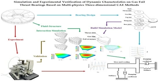
3. CAE Simulation Method Using Multi-Physics Modules

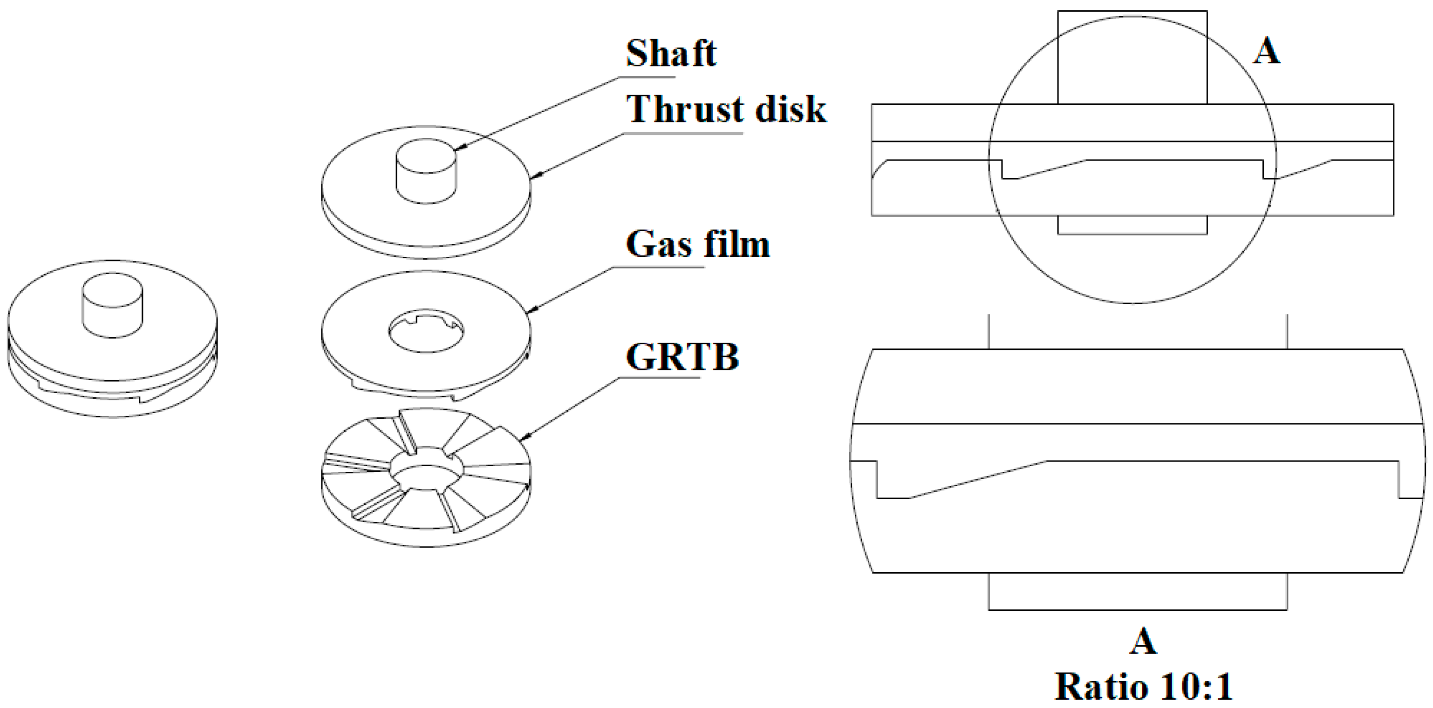
3.1. Basic Geometric Model

In GFTB applications, it is common to see two GFTBs clamped on both sides of the rotor’s thrust disk so that the rotor can be stabilized via the support provided by the two GFTBs. However, the design and analysis process should start during the validation of the three-dimensional (3D) geometric model to be used for all of the solution modules in CAE simulation systems. Hence, to verify the validity of the basic geometric model, this study selected a single-side GRTB with an inner diameter of 22 mm and an outer diameter of 73 mm rotating on a gas film with a thickness difference of 28 microns used for the DUT (the researchers designed the GRTB so that the rotor could be loaded with 200 N axial force at 78.5 krpm). The DUT was fabricated using the aluminum alloy Al6061-T6 for experimental verification purposes, as shown in Figure 4. Using the experimental measurements for the load forces, a basic geometric model could be employed to verify the multi-physics CAE simulations to be used for the later fluid–structure interaction (FSI) analysis of the clamped-rotor GFTBs.

3.2. Model Meshing and Boundary Conditions

To ensure that simulation packages achieve convergent results, an appropriate mesh size and appropriate mesh layers must be determined for comparison with the experimental results; the boundary conditions of the geometric model must also be set to the correct values. Table 1 lists the model’s geometric dimensions and the corresponding mesh layers of the gas film, and a schematic drawing of the GRTB model is shown in Figure 5. As for the corresponding boundary conditions for the geometric model shown in Figure 5, Table 2 tabulates the pertinent values and descriptions of the boundary conditions with denotations. The mesh used for the gas film is a hexahedral and linear mesh.

3.3. Experimental Verifications of the GRTB

To verify the GRTBs modelled in the previous sections, an experimental bench instrumented with appropriate sensors and high-speed motor dive was built in-house to measure the loading capacity under various operational conditions, namely, speed and gas film thickness. A Kistler® piezoelectric load cell, Model 9217A (Kistler, Shanghai, China), was used to measure the axial load forces on the base of the GRTB, whereas the thrust disk was driven by a rotor that was rigidly clamped to the high-speed motor. A granite table with a height adjustment screw was used to set the micron adjustment of the gas film thickness. Figure 6 shows a photo of a bench made from extruded aluminum alloy bars. A digital tachometer and infrared temperature probe (BOSCH, Stuttgart, Germany) were used to monitor the motor speed and ambient temperature. The load forces were recorded using an industrial data-acquisition PC (ASUS, Taipei, Taiwan) with data-logging capabilities.
After the experimental data were processed and plotted, the same ambient conditions and rational speeds were entered into the CAE simulation packages to obtain the simulated load force results. In the working fluid of the bearing, air is assumed to be the ideal gas. The results are plotted in Figure 7, Figure 8 and Figure 9. The difference in the three figures is the gas film thickness. Compared to the previously published numerical results of GFTBs reported by Heshmat et al. [25], the load force simulation results agree well with both the experimental data and the predicted results from the literature. Therefore, the dynamic simulation method tested for the GRTBs seems to be able to predict the load forces successfully. Hence, it should be noted that the foil structure supporting the GFTBs should be further explored since the structural mechanical modules have been thoroughly studied in the last century. The process is concisely described in the following sections.

4. FSI Computational Environment

4.1. Analysis Process for Transient Dynamic GFTB

After the CAE model for GRTBs was verified successfully, the goal was to include all of the physical elements of the GFTBs, namely, the solid region with the thrust disk and the foil structure and fluid region in the gas film, so that the interactions between the elements could be accounted for. The complete solid and liquid regions were established using a commercial CAE software package: Ansys 19.0, copyrighted by Ansys Inc., Canonsburg, PA, USA. The built-in multi-physics simulation environment allows for the exploration of the dynamic characteristics of GFTBs. Meanwhile, the heat transfer between the top foil surface and gas film could be analyzed via a heat transfer coefficient defined at the solid and fluid interface. The process flow chart for the GFTB simulation method under the FSI computational environment is shown in Figure 10.

4.2. Model Meshing and Boundary Conditions

It is evident that the complete geometric model of the GFTB is much more complex than the one for the GRTB. In this situation, the thrust disk and foil structure must be meshed in a separate geometric model. The schematic model is illustrated in Figure 11 and shows three connected geometries. Additionally, the corresponding dimensions and mesh size and layers are listed in Table 3. As for the boundary conditions, Table 4 tabulates the boundary conditions as well as outlines the mesh connection methods and describes the three regions. It should be noted that any incorrect boundary values could lead to divergent results with errors or warning messages in the computational environment. The gas film mesh, foil structure, and thrust disk were hexahedral and linear.

4.3. Dynamic Simulation Results for Single-Side GFTBs

In general, the transient simulation of any type of system stops when the results show steady-state behavior. It could be oscillatory or constant, as justified by the physical phenomenon. Figure 12 plots the transient displacement of the thrust disk of the GFTB in an underdamped oscillation in axial motion. It should be noted that the time-historic plots of the thrust disk displacement can be used to assess the dynamic characteristics of the GFTBs. Table 5 lists the pertinent parameters for the dynamic simulations of the DUT, with the ambient conditions being set at 50 °C and 2 Bar (E-4 GPa). In the table, the stiffness of the foil structure is set at 0.1 GPa; this is the equivalent structural stiffness of the bump-type foil published by Heshmat et al. [25]. Additionally, the equivalent structural stiffness of the foil structure is consistent in the foil structure analysis model reported by K. Feng and S. Kaneko [38]. The foil structure was made using a material with a Young’s modulus and Poisson ratio of 214 GPa and 0.3, respectively. Figure 13 shows the layout of the foil structure used in the simulation process. At the beginning of the simulation, the thrust disk was set at a distance of 10 microns from the highest surface of the top foil of the GFTBs under the thrust disk. After a certain amount of time has elapsed, the thrust disk will settle into its new position because of the viscous damping from the gas film.

4.4. Mass Spring Dashpot Model for GFTBs

Because the operational principle of GFTBs is based on the resultant forces contributed by the pressure distribution of the thin gas film between the rotational thrust pad and top foil, the resultant forces counterbalance the load forces exerted on the thrust disk along the axial direction. Hence, the thrust disk may vibrate on the GFTB sometimes and damp out later. In dynamic systems analysis, it is essential to transform the time domain results to the frequency domain due to the simplicity of characterizing the dynamic properties of the system. Therefore, if the stiffness and damping characteristics of GFTBs can be represented by frequency domain factors, the dynamic characteristics of GFTBs can be comprehended in a more intuitive sense. Since the rotor in GFTBs exhibits underdamped oscillation motions, the stiffness and damping coefficients can be deduced from the governing equation of the underdamped oscillation at a given rotational speed. The governing equation of underdamped oscillatory systems can be seen in Equation (2). Based on the equation, the stiffness and damping coefficients defined in Equation (3) for the single-sided GFTB are deduced to be 4.35E+6 N/m and 375 N-s/m, respectively. In the equations, m is the mass, x is the displacement, c is the damping coefficient, k is the stiffness, A0 is the initial displacement, and t is the time. Figure 14 illustrates the corresponding transient plots of the underdamped oscillatory rotor displacement for comparison. It should be further noted that the contour plots of the steady-state gas film pressure, temperature, and corresponding foil surface displacement of the single GFTBs rotating at 78.5 krpm and under a load force of 200 N can be seen Figure 15, Figure 16, and Figure 17, respectively. Those simulation results can be obtained until the bearings reach a quasi-steady state after a period of time in which the state process is transient.
m d 2 x d t 2 + c d x d t + k x = 0
x = A 0 · e γ · c o s ( ω t ) ,   ω = ω 0 2 γ 2 ,     2 γ = c m ,     ω 0 2 = k m

5. Case Study: Clamped-Rotor GFTB Design

In most GTFB designs, two GFTBs are placed on each side of the thrust disk to clamp the rotor to provide support during axial motion during nominal operation. Therefore, it is necessary that the method proposed in the previous sections be applied to analyze the clamped-rotor design. Figure 18 depicts model meshes for the clamped rotor that are similar to those used for the single-side-supported thrust disk. Setting the rotor at various initial average clearances between the two GFTBs, the transient simulations show plots with specific dynamic characteristics, as shown in Figure 19. By applying the mass spring dashpot model, the corresponding stiffness and damping coefficients plotted versus the initial average clearances indicate the stiffness and damping capacity if the design for the given initial clearances is as shown in Figure 20. That is to say, if the film thickness is not designed correctly, then the GFTBs could experience a catastrophic disaster due to improper stiffness and damping coefficients. As a further step, the GFTBs may wear out gradually as the stiffness and damping capacity continue to decrease until failure kicks in.

6. Conclusions and Discussion

A multi-physics CAE simulation method to study the dynamic characteristics of GFTBs is presented in this paper. CAE simulations were conducted using a commercial CAE software package and were based on both thermo-fluid and mechanical modules. Using process-flow windows, the proposed simulation method can analyze the dynamic thermofluidic flow field coupled with the elastic deformation of the interfacial boundaries under quasi-steady operating conditions for given model configurations.
To verify the accuracy and efficacy of the simulation method, an experimental bench was built in-house to mimic the loading forces of the thrust disk on a GRTB under various rotational speeds and adjustable gas film thickness. As shown in Figure 7, Figure 8 and Figure 9, the experimental measurements agree well with the simulated results when assuming negligible effects of linear elastic bump support. Therefore, the approach of adopting a more complex clamped-rotor design for dynamic characteristics seems to be feasible in practice.
In this paper, the researchers built a 3D FSI model to simulate the working characteristic during GFTB operation using the transient analysis method until the system finally reached a quasi-steady state. Then, the dynamic and static properties of the bearing system could be obtained. Since the simulated outputs display not only the pressure and temperature contours of the working fluid but also the elastic deformation contours of the thrust disk and the top foil according to the transient simulation at each time step, it would be interesting to explore the rotor’s dynamic characteristics in the axial direction based on the transient simulation outputs. It should also be noted that the underdamped oscillatory motions of the rotor are repeatedly exhibited in the transient displacement plots of the rotor under various load forces and gas film thicknesses, forming the results of the DUTs.
Based on the observations from the simulated transient plots, a linear model consisting of a spring and a damper is proposed to describe the underdamped oscillatory motions of the rotor. That is, the natural frequency and damping factor of the rotor running under nominal speed can be deducted from the transient simulations. Therefore, for the clamped-rotor case running at 78.5 krpm, the plots derived from the simulated results illustrate the equivalent stiffness and damping of the clamped-rotor GFTB installed with various initial gap clearances. This rationale could contribute significant progress in the design and diagnostics of GFTBs because the basic operating dynamic characteristics can be simulated immediately after the design has been determined. Conclusively speaking, the proposed CAE method could help GFTB design engineers comprehend the dynamic performance of GFTBs, and illustrates a feasible approach for the implementation of GFTBs into digital twin machine architectures in the metaverse.

Author Contributions

Conceptualization, methodology, software, validation, formal analysis, investigation, resources, data curation, writing—original draft preparation, visualization, T.-Y.Y. Writing—review and editing, supervision, project administration, P.-J.W. All authors have read and agreed to the published version of the manuscript.

Funding

This research received no external funding.

Data Availability Statement

Some of the data presented in this study are available in Figure 7, Figure 8 and Figure 9 of this paper and the data that support the findings of this study are available from the corresponding author upon reasonable request.

Conflicts of Interest

The authors declare no conflict of interest.

Nomenclature

The following nomenclature is used in this manuscript:
Abbreviations
3DThree-dimensional
CAEComputer-aided engineering
DUTDevice under test
GFBsGas foil bearings
GFTBsGas foil thrust bearings
GRTBsGas rigid thrust bearings
HGFBsHybrid gas foil bearing
Notation
A0Initial displacement, m
cDamping coefficient, N·s/m
hFilm height, m
kStiffness, N/m
mMass, kg
pAerodynamic pressure, Pa
uTangential velocity, m/s
tTime, s
xNormal coordinates in cylindrical coordinate system or displacement, m
yTangential coordinates in cylindrical coordinate system, m
zBearing axial coordinate in cylindrical coordinate system, m
Greek symbols
μDynamic viscosity, Pa-s
ρLubricant density, kg/m3

References

  1. Peng, J.P.; Carpino, M. Calculation of Stiffness and Damping Coefficients for Elastically Supported Gas Foil Bearings. ASME J. Tribol. 1993, 115, 20–27. [Google Scholar] [CrossRef]
  2. Carpino, M.; Talmage, G. A Fully Coupled Finite Element Formulation for Elastically Supported Foil Journal Bearings. STLE Tribol. Trans. 2003, 46, 560–565. [Google Scholar] [CrossRef]
  3. Carpino, M.; Talmage, G. Prediction of Rotor Dynamic Coefficients in Gas Lubricated Foil Journal Bearings with Corrugated Sub-Foils. STLE Tribol. Trans. 2006, 49, 400–409. [Google Scholar] [CrossRef]
  4. San Andrés, L.; Kim, T.H. Improvements to the Analysis of Gas Foil Bearings: Integration of Top Foil 1D and 2D Structural Models; Paper No. GT2007-27249; ASME: New York, NY, USA, 2007. [Google Scholar]
  5. Kim, T.H.; San Andrés, L. Analysis of Advanced Gas Foil Bearings with Piecewise Linear Elastic Supports. Tribol. Int. 2007, 40, 1239–1245. [Google Scholar] [CrossRef]
  6. Ku, C.-R.; Heshmat, H. Compliant Foil Bearing Structural Stiffness Analysis: Part I—Theoretical Model Including Strip and Variable Bump Foil Geometry. ASME J. Tribol. 1992, 114, 394–400. [Google Scholar] [CrossRef]
  7. Lee, D.; Kim, Y.; Kim, T. The Dynamic Performance Analysis of Foil Journal Bearings Considering Coulomb Friction: Rotating Unbalance Response. STLE Tribol. Trans. 2009, 52, 146–156. [Google Scholar] [CrossRef]
  8. Kim, D. Parametric Studies on Static and Dynamic Performance of Air Foil Bearings with Different Top Foil Geometries and Bump Stiffness Distributions. ASME J. Tribol. 2007, 129, 354–364. [Google Scholar] [CrossRef]
  9. Le Lez, S.; Arghir, M.; Frene, J. Static and Dynamic Characterization of a Bump-Type Foil Bearing Structure. ASME J. Tribol. 2007, 129, 75–83. [Google Scholar] [CrossRef]
  10. Heshmat, H. Advancements in the Performance of Aerodynamic Foil Journal Bearings: High Speed and Load Capacity. ASME J. Tribol. 1994, 116, 287–295. [Google Scholar] [CrossRef]
  11. Song, J.; Kim, D. Foil Gas Bearing with Compression Springs: Analyses and Experiments. ASME J. Tribol. 2007, 129, 628–639. [Google Scholar] [CrossRef]
  12. Heshmat, H. Operation of Foil Bearings Beyond the Bending Critical Mode. ASME J. Tribol. 2000, 122, 192–198. [Google Scholar] [CrossRef]
  13. Howard, S.A.; DellaCorte, C. Steady-State Stiffness of Foil Air Journal Bearings at Elevated Temperatures. STLE Tribol. Trans. 2001, 44, 489–493. [Google Scholar] [CrossRef]
  14. Howard, S.A.; DellaCorte, C. Dynamic Stiffness and Damping Characteristics of a High-Temperature Air Foil Journal Bearing. STLE Tribol. Trans. 2001, 44, 657–663. [Google Scholar] [CrossRef]
  15. Lubell, D.; DellaCorte, C.; Stanford, M. Test Evolution and Oil-Free Engine Experience of a High Temperature Foil Air Bearing Coating; Paper No. GT2006-90572; ASME: New York, NY, USA, 2006. [Google Scholar]
  16. Radil, K.; Howard, S.; Dykas, B. The Role of Radial Clearance on the Performance of Foil Air Bearings. STLE Tribol. Trans. 2002, 45, 485–490. [Google Scholar] [CrossRef]
  17. Dykas, B.; Howard, S.A. Journal Design Considerations for Turbomachine Shafts Supported on Foil Air Bearings. STLE Tribol. Trans. 2004, 47, 508–516. [Google Scholar] [CrossRef]
  18. Lee, D.; Kim, D. Thermo-Hydrodynamic Analyses of Bump Air Foil Bearings with Detailed Thermal Model of Foil Structures and Rotor. ASME J. Tribol. 2010, 132, 021704. [Google Scholar] [CrossRef]
  19. San Andrés, L.; Kim, T.H. Thermohydrodynamic Analysis of Bump Type Gas Foil Bearings: A Model Anchored to Test Data; Paper No. GT2009-59919; ASME: New York, NY, USA, 2009. [Google Scholar]
  20. Peng, Z.C.; Khonsari, M. A Thermohydrodynamic Analysis of Foil Journal Bearings. ASME J. Tribol. 2006, 128, 534–541. [Google Scholar] [CrossRef]
  21. Feng, K.; Kaneko, S. A Study of Thermohydrodynamic Features of Multiwound Foil Bearing Using Lobatto Point Quadrature; Paper No. GT2008-50110; ASME: New York, NY, USA, 2008. [Google Scholar]
  22. Martowicz, A.; Zdziebko, P.; Roemer, J.; Zywica, G.; Baginski, P. Thermal Characterization of a Gas Foil Bearing—A Novel Method of Experimental Identification of the Temperature Field Based on Integrated Thermocouples Measurements. Sensors 2022, 22, 5718. [Google Scholar] [CrossRef]
  23. Hou, Y.; Zhao, Q.; Guo, Y.; Ren, X.; Lai, T.; Chen, S. Application of Gas Foil Bearings in China. Appl. Sci. 2021, 11, 6210. [Google Scholar] [CrossRef]
  24. Liu, X.; Li, C.; Du, J.; Nan, G. Thermal Characteristics Study of the Bump Foil Thrust Gas Bearing. Appl. Sci. 2021, 11, 4311. [Google Scholar] [CrossRef]
  25. Heshmat, H.; Walowit, J.A.; Pinkus, O. Analysis of Gas Lubricated Compliant Thrust Bearings. ASME J. Lubr. Technol. 1983, 105, 638–646. [Google Scholar] [CrossRef]
  26. Heshmat, C.A.; Xu, D.S.; Heshmat, H. Analysis of Gas Lubricated Foil Thrust Bearings Using Coupled Finite Element and Finite Difference Methods. ASME J. Tribol. 2000, 122, 199–204. [Google Scholar] [CrossRef]
  27. Iordanoff, I. Analysis of an Aerodynamic Compliant Foil Thrust Bearing: Method for a Rapid Design. ASME J. Tribol. 1999, 121, 816–822. [Google Scholar] [CrossRef]
  28. Bruckner, R.J. Simulation and Modeling of the Hydrodynamic, Thermal, and Structural Behavior of Foil Thrust Bearings. Ph.D. Thesis, Case Western Reserve University, Cleveland, OH, USA, 2004. [Google Scholar]
  29. Dykas, B.; Bruckner, R.J.; DellaCorte, C.; Edmonds, B.; Prahl, J. Design, Fabrication, and Performance of Foil Gas Thrust Bearings for Microturbomachinery Applications; Paper No. GT2008-50377; ASME: New York, NY, USA, 2008. [Google Scholar]
  30. Park, D.J.; Kim, C.H.; Jang, G.H.; Lee, Y.B. Theoretical Considerations of Static and Dynamic Characteristics of Air Foil Thrust Bearing with Tilt and Slip Flow. Tribol. Int. 2008, 41, 282–295. [Google Scholar] [CrossRef]
  31. DellaCorte, C.; Edmonds, B.J. Preliminary Evaluation of PS300: A New Self-Lubricating High Temperature Composite Coating for Use to 800 °C; Technical Report No. NASA TM-107056; NASA: Greenbelt, MD, USA, 1995. [Google Scholar]
  32. Stanford, M.K.; Yanke, A.M.; DellaCorte, C. Thermal Effects on a Low Cr Modification of PS304 Solid Lubricant Coating; Technical Report No. NASA TM-2003-213111; NASA: Greenbelt, MD, USA, 2004. [Google Scholar]
  33. Kim, D.; Park, S. Hydrostatic Air Foil Bearings: Analytical and Experimental Investigations. Tribol. Int. 2009, 42, 413–425. [Google Scholar] [CrossRef]
  34. Kim, D.; Kumar, M. Load Capacity Measurements of Hydrostatic Bump Foil Bearing; Paper No. T2009-T59286; ASME: New York, NY, USA, 2009. [Google Scholar]
  35. Kumar, M.; Kim, D. Parametric Studies on Dynamic Performance of Hybrid Air Foil Bearings. ASME J. Eng. Gas Turbines Power 2008, 130, 62501. [Google Scholar] [CrossRef]
  36. Kim, D.; Lee, D. Design of Three-Pad Hybrid Air Foil Bearing and Experimental Investigation on Static Performance at Zero Running Speed. ASME J. Eng. Gas Turbines Power 2010, 132, 122504. [Google Scholar] [CrossRef]
  37. Constantinescu, V.N. Basic Relationships in Turbulent Lubrication and Their Extension to Include Thermal Effects. ASME J. Lubr. Technol. 1973, 95, 147–154. [Google Scholar] [CrossRef]
  38. Feng, K.; Kaneko, S. Analytical Model of Bump-Type Foil Bearings Using a Link-Spring Structure and a Finite-Element Shell Model. ASME J. Tribol. 2010, 132, 021706. [Google Scholar] [CrossRef]
Figure 1. Schematic drawing of a typical single-side GFTB with basic components shown blown up on the left; on the right, A shows a blown-up side view in detail, showing a stacked top foil and bump foil stacked to create pressure in the gas film to support the thrust disk when bearing is operating.
Lubricants 10 00222 g001
Figure 2. Schematic drawing of the GRTB structure illustrated by Iordanoff [27]; on the right, A shows the ramp and parallel gap design.
Lubricants 10 00222 g002
Figure 3. The six-pad GFTB design employed for the DUT, where x, y, and h denote the coordinates of the fluid field equation.
Lubricants 10 00222 g003
Figure 4. Photo of the GRTB DUT manufactured using the aluminum alloy Al6061-T6.
Lubricants 10 00222 g004
Figure 5. Schematic illustration of the denotation of the geometric dimensions and boundary conditions of the gas film used for the GRTB. Refer to Table 1 for the correct number of mesh layers.
Lubricants 10 00222 g005
Figure 6. Photo of the experimental bench built for thrust force measurement; A is the load cell attached to the stationary support, whereas B is the rotating rotor driven by a high-speed motor.
Lubricants 10 00222 g006
Figure 7. Comparisons between experimental and simulated load capacity with gas film thickness at 37 microns; the red symbols with error bars are the experimental data, whereas the blue line is the simulated results. The orange line represents results previously published in [25].
Lubricants 10 00222 g007
Figure 8. Same as Figure 7, except the gas film thickness is 44 microns.
Lubricants 10 00222 g008
Figure 9. Same as Figure 7, except the gas film thickness is 51 microns.
Lubricants 10 00222 g009
Figure 10. Flow chart for GFTB simulation method including processes in FSI computational environment.
Lubricants 10 00222 g010
Figure 11. Schematic model with meshes in the fluid and the solid regions representing the complete GFTB according to the axis symmetry assumption. Refer to Table 1 and Table 3 for the correct number of mesh layers.
Lubricants 10 00222 g011
Figure 12. Plot of simulated transient gas film thickness of the single-side-supported GFTB starting from the given initial position to steady state at 4.2 microns.
Lubricants 10 00222 g012
Figure 13. Schematic of the layout and the measurements of the foil structure used in the simulation process.
Lubricants 10 00222 g013
Figure 14. Plots of under-damped linear oscillatory transient gas film thickness compared to the simulated single-side-supported GFTB results. The blue line shows the cosinusoidal characteristics, and the orange line shows the exponential characteristics.
Lubricants 10 00222 g014
Figure 15. Simulated nominal pressure distribution on thrust disk of GFTB operated at 78.5 krpm with load thrust of 200 N.
Lubricants 10 00222 g015
Figure 16. Same as in Figure 15, except the plot shows the nominal gas temperature distribution.
Lubricants 10 00222 g016
Figure 17. Same as in Figure 15, except the plot shows the nominal top foil surface displacement distribution. The root mean square value of the displacement of the whole top foil is 0.3505 microns.
Lubricants 10 00222 g017
Figure 18. Schematic model with meshes in the fluid and solid regions of the clamped-rotor GFTB used as the DUT, with the complete bearing represented by axis symmetry assumption. Refer to Table 1 and Table 3 for the correct number of mesh layers.
Lubricants 10 00222 g018
Figure 19. Composite plots of transient rotor disk displacement of the two DUTs with various initial average gap clearances; A represents the single side, B represents 10 microns, C represents 12.5 microns, D represents 15 microns, E represents 17.5 microns, F represents 20 microns, G represents 25 microns, and H represents 30 microns.
Lubricants 10 00222 g019
Figure 20. Plots of effects of initial average clearance on the calculated equivalent stiffness and damping coefficient of the clamped-rotor GFTB; the two dashed lines are the corresponding values of the single-side GFTB serving as the base reference.
Lubricants 10 00222 g020
Table 1. Geometric dimensions of the model and corresponding mesh layers of the gas film shown in Figure 5.
Edge DenotationLength/AngleMesh Layers
A36.5 mmNA
B11.0 mmNA
C10 microns24
D46.60°20
E11.83°5
F1.0 mm4
G38 microns24
H25.5 mm30
Table 2. CAE model boundary conditions at gas film interfaces shown in Figure 5.
Surface NameDenotationBoundary ConditionValue
Thrust disk contact surfaceIRotational speed6–16 krpm
Interface of the neighbor gas filmJEnvironment pressure1 Bar
Environment temperature293 K
GRTB contact surfaceKFixed wallFixed
Ambient interface at outer edge of gas filmLEnvironment pressure1 Bar
Environment temperature293 K
Interface of the last gas filmMEnvironment pressure1 Bar
Environment temperature293 K
Ambient interface at inner edge of gas filmNEnvironment pressure1 Bar
Environment temperature293 K
Table 3. Model mesh denotation with dimensions and layer numbers for the complete GFTB as the DUT.
Edge DenotationLength/AngleMesh Layers
O60°29
P4 mm2
Q0.8197mm4
Table 4. Same as in Table 3, but the table outlines the boundary conditions.
RegionSurface NameDenotationBoundary ConditionValue
SolidInterface of the next part of the thrust diskRFree movement along axial directionAxis
Sym
Upper surface of the thrust diskSFree movement along axial directionFree
Outer surface of the thrust diskTFree movement along axial directionFree
Gas film contact surface in lower surface of thrust diskUInterface between thrust disk and gas filmMatch
Inner surface of the thrust diskVFree movement along axial directionFree
Interface of the previous pad of the thrust diskWRotational symmetryAxis
Sym
FluidInterface of the next pad’s gas filmXEnvironment pressure2 Bar
Environment temperature323 K
Thrust disk contact surfaceYInterface between thrust disk and gas film and rotational speedMatch
Interface of the environment at outer edge of gas filmZEnvironment pressure2 Bar
Environment temperature323 K
Interface of the environment at inner edge of gas filmAAEnvironment pressure2 Bar
Environment temperature323 K
GFTB contact surface of gas filmBBInterface between foil structure and gas filmMatch
Interface of the last gas filmCCEnvironment pressure2 Bar
Environment temperature323 K
SolidGas film contact surface on upper surface of GFTBsDDInterface between foil structure and gas filmMatch
Interface of the next pad of the GFTBsEEFree movementAxis
Sym
Outer surface of the GFTBFFFree movement along axial directionFree
Lower fixed surface of the GFTBsGGFixed wallFixed
Inner surface of the GFTBsHHFree movement along axial directionFree
Interface of the last part of the GFTBsIIFree movement along axial directionAxis
Sym
Table 5. List of pertinent parameters employed for the transient simulations.
Parameter DefinitionParameter Values and Unit
Working fluidAir (ideal gas model)
Initial gas film pressure2.0 (Bar)
Initial gas film temperature323 (K)
Environment pressure2.0 (Bar)
Environment temperature323 (K)
Foil structure stiffness0.1 (GPa)
Shaft rotational speed78.5 (krpm)
Heat transfer coefficient of surface
of thrust disk and GFTBs
100 (W·m−2·K−1)
Temperature of surface
of thrust disk and GFTBs
323 (K)
Shaft normal load200 (N)
Shaft mass1.0 (kg)
Initial distance between two GFTB surfaces
(if there are two GFTBs in the model)
4.02, 4.025, 4.03,4.035, 4.04, 4.05, 4.06 (mm)
Thrust disk thickness4 (mm)
Configuration of GFTBsSingle side and clamped rotor
Initial position of the thrust disk10 microns from the top surface of bottom GFTB
Publisher’s Note: MDPI stays neutral with regard to jurisdictional claims in published maps and institutional affiliations.

