Fretting Fatigue in Mechanical Joints: A Literature Review

 ,
,  , , , and
Abstract
:1. Introduction
- Wear of the surfaces;
- A considerable reduction in fatigue life.
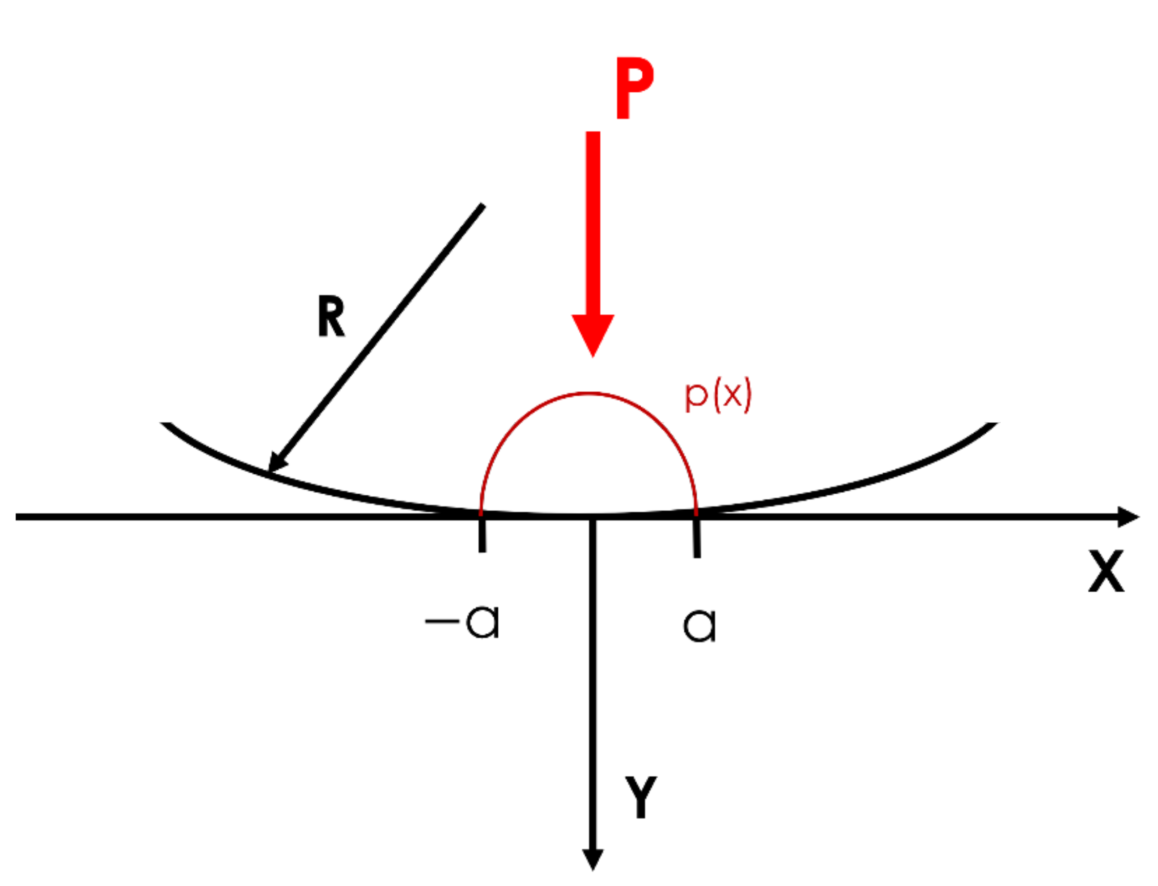
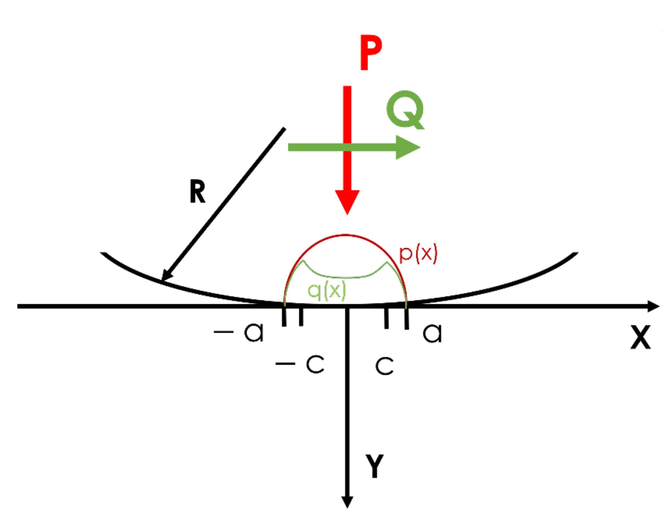
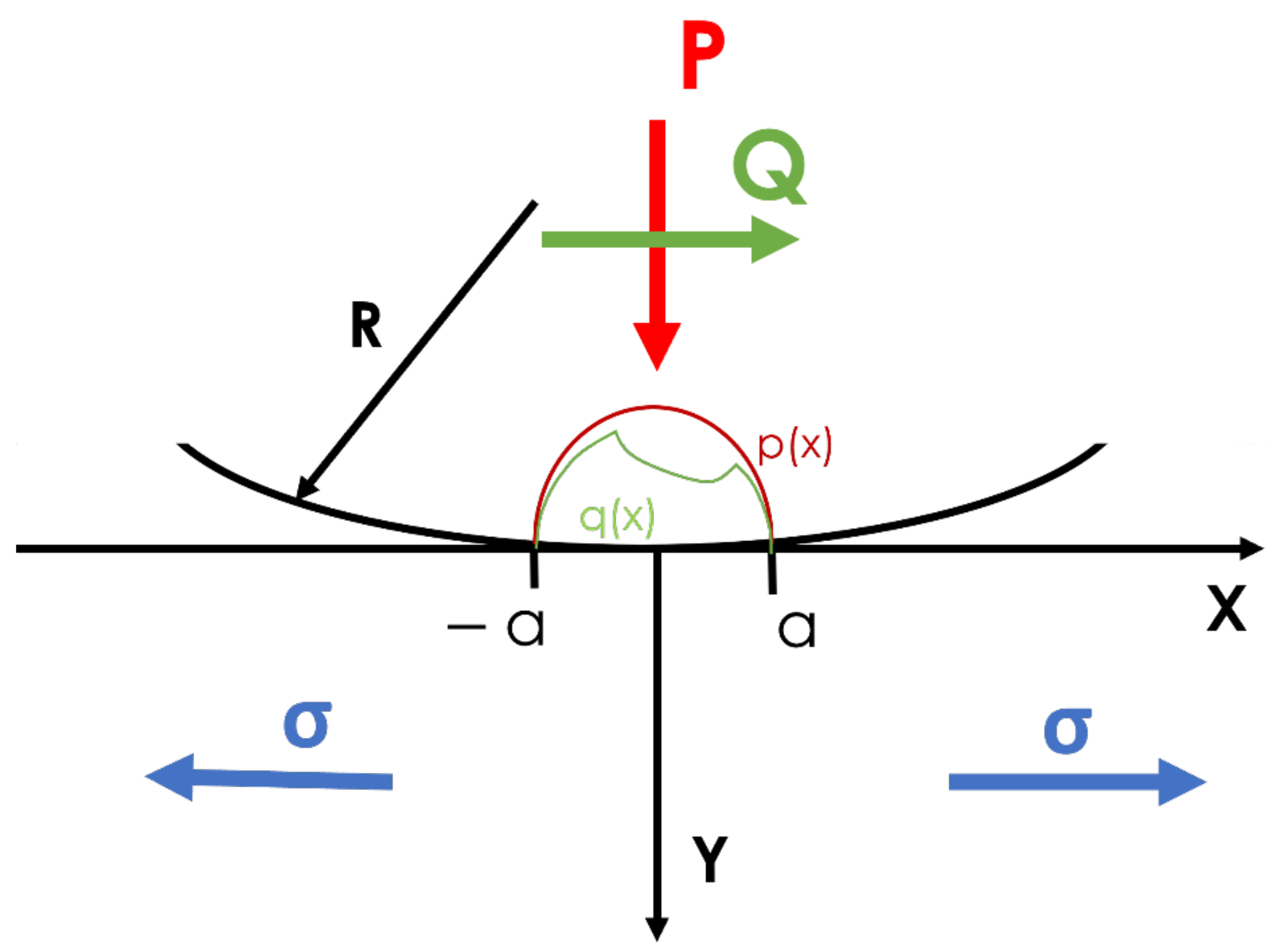
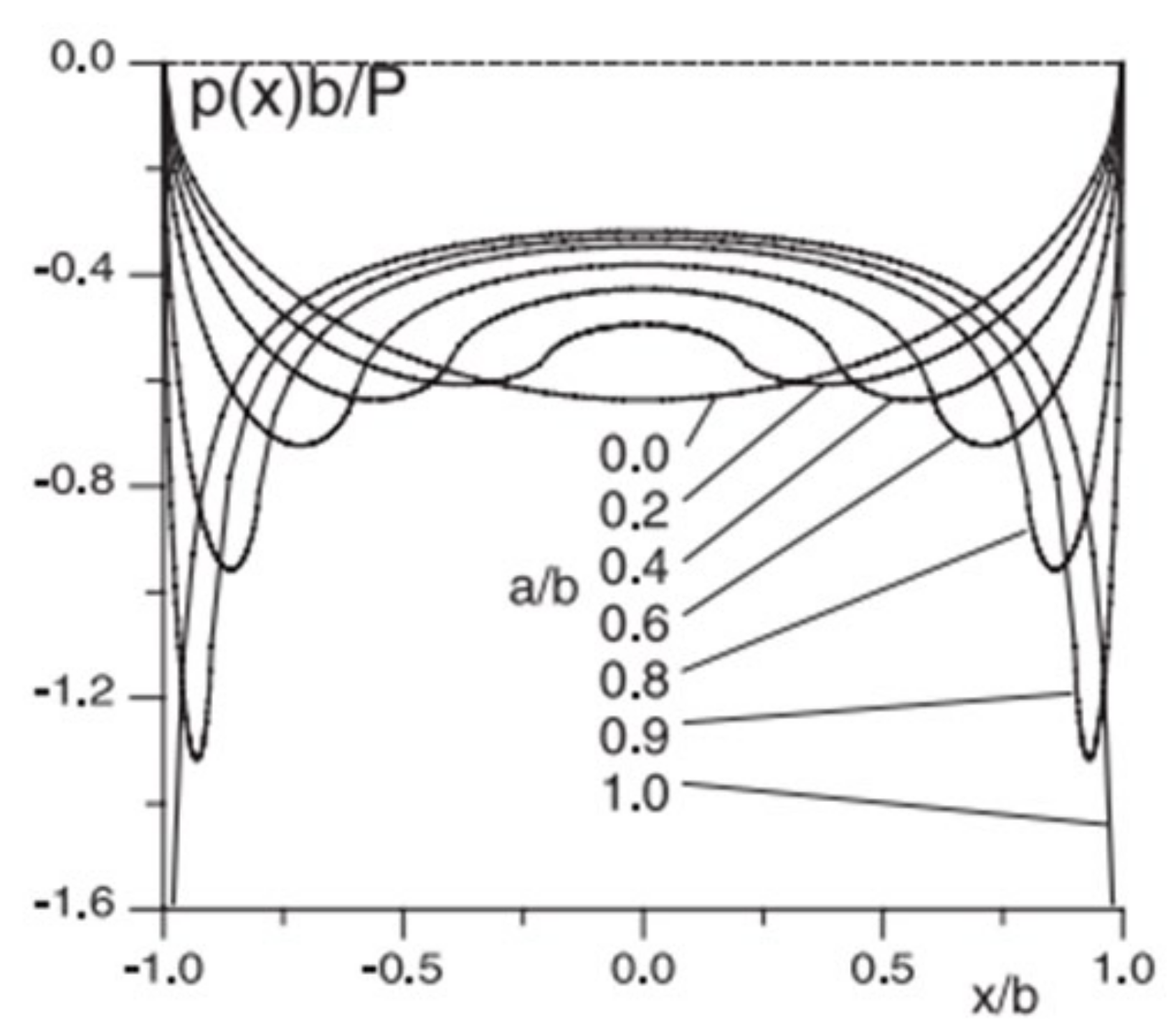
1.1. Contact Mechanics
- if
- if

1.2. Fretting Damage in Structural Joints
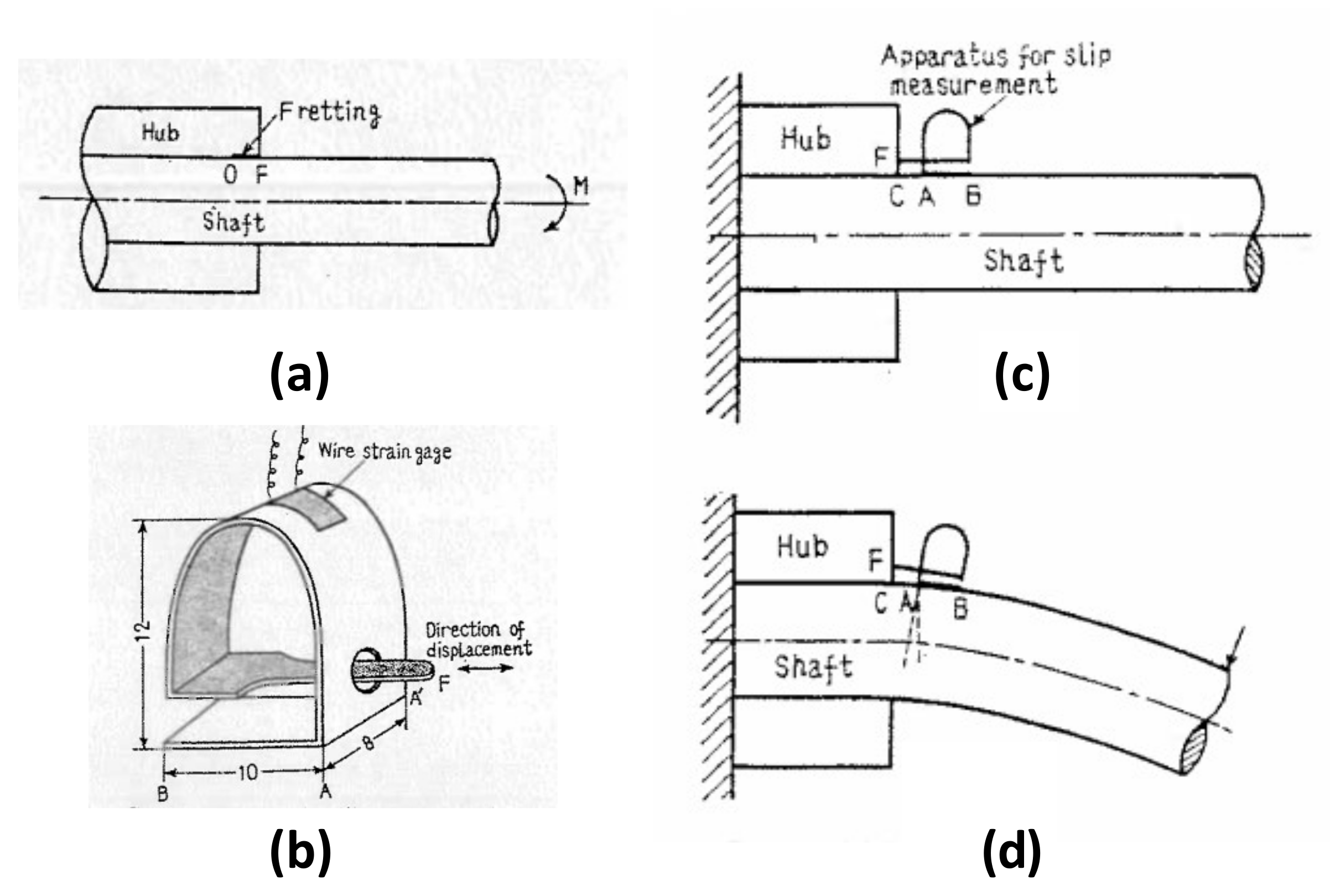
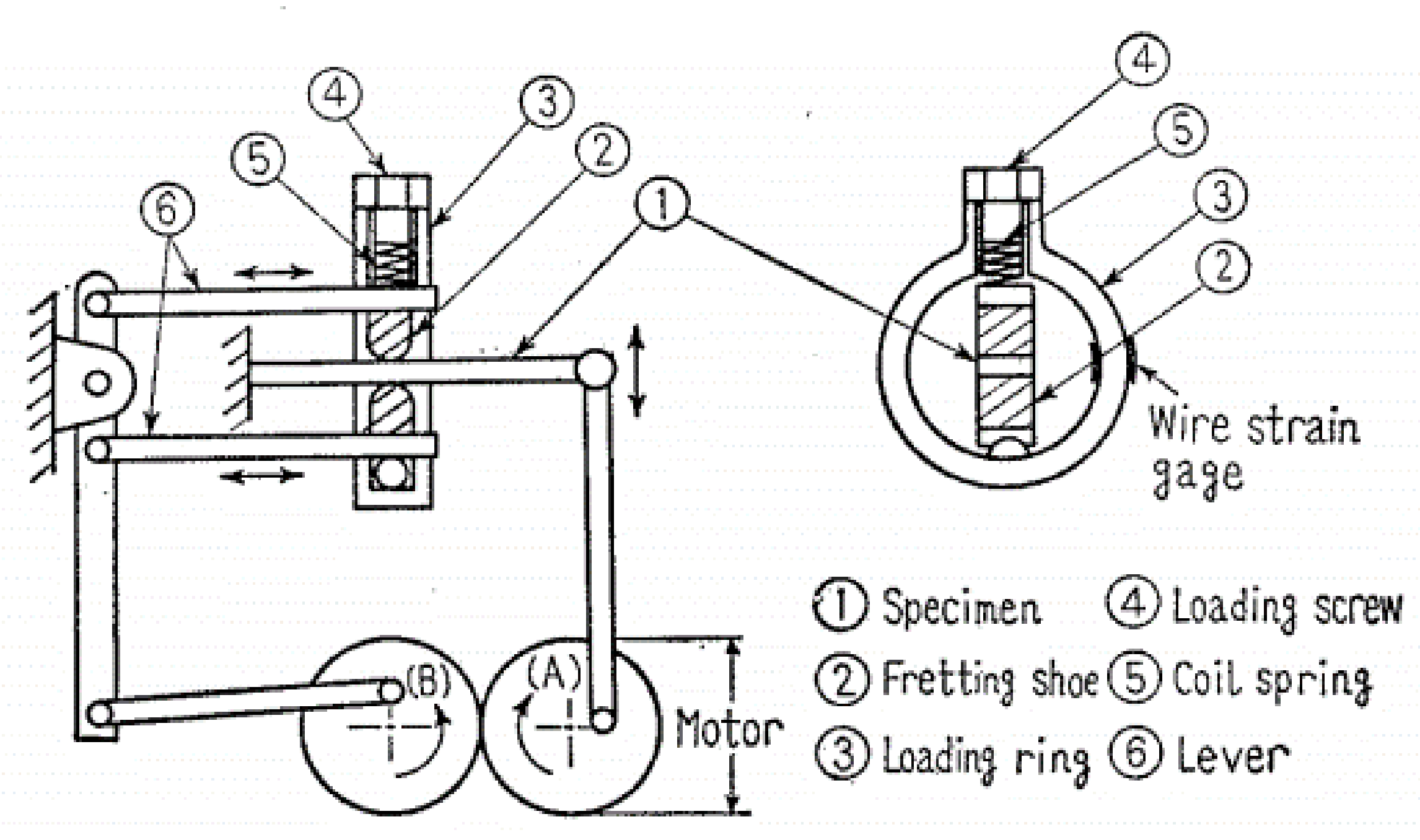
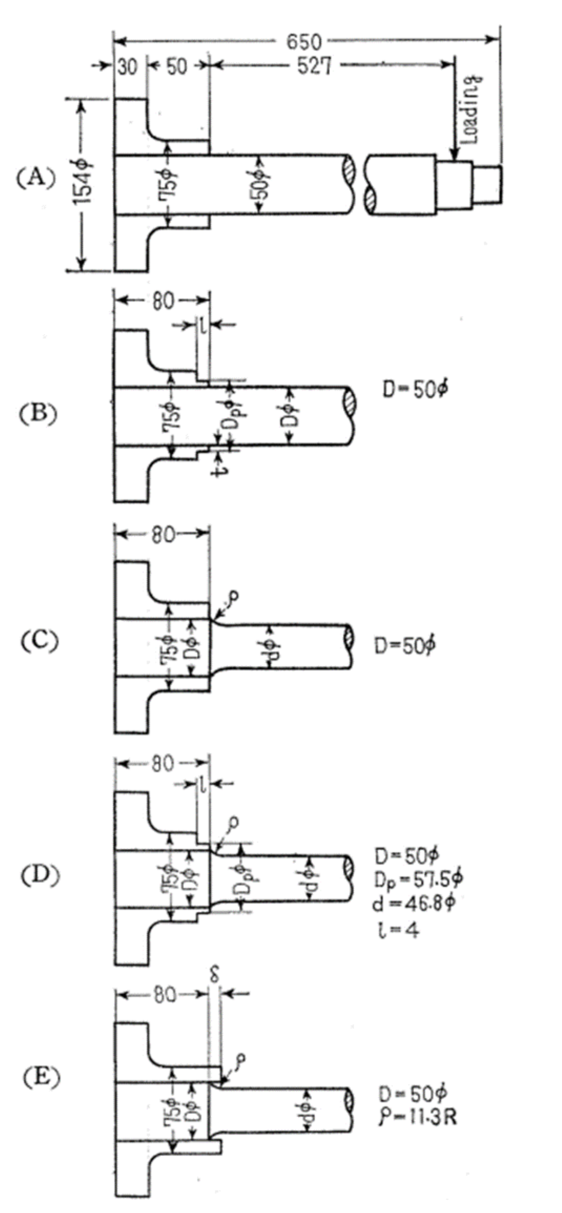
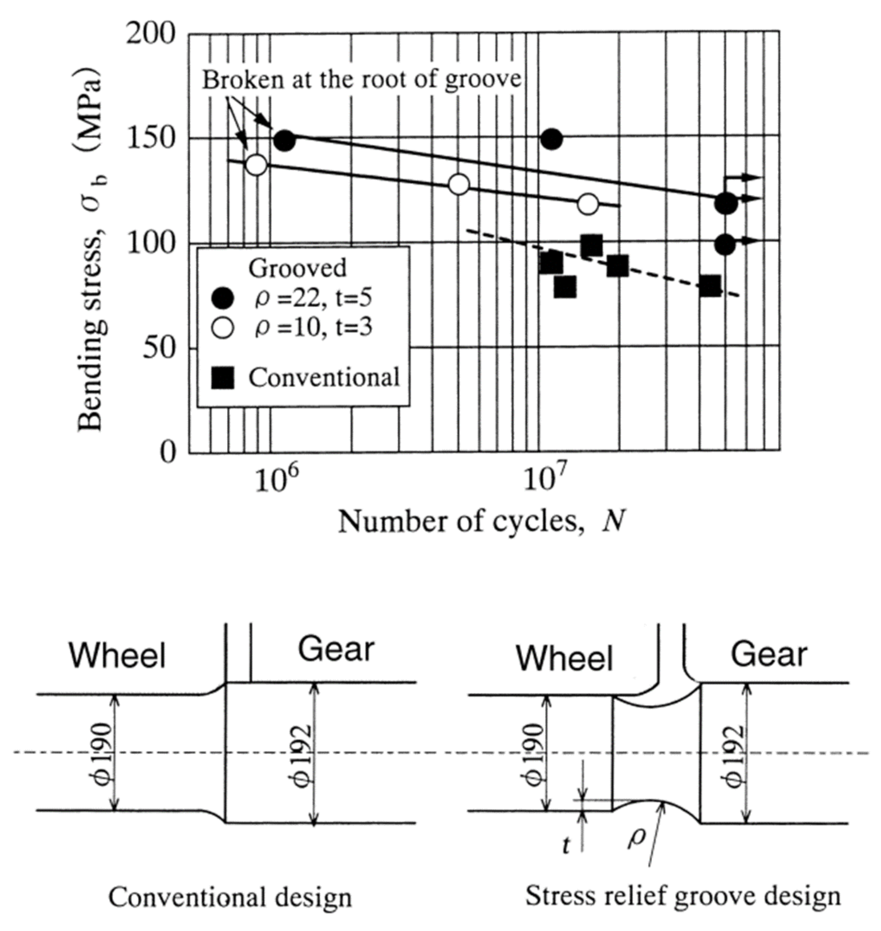
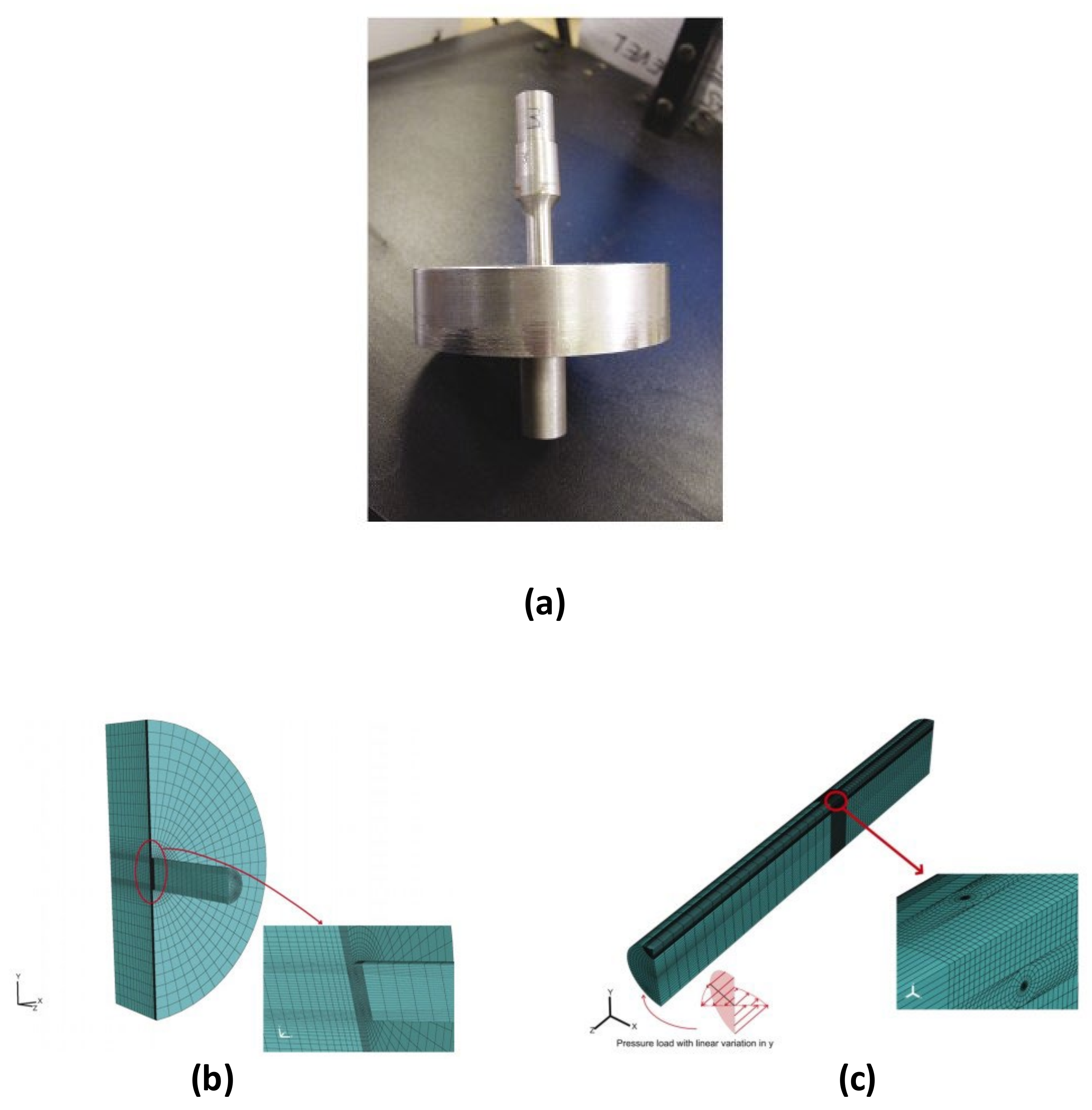
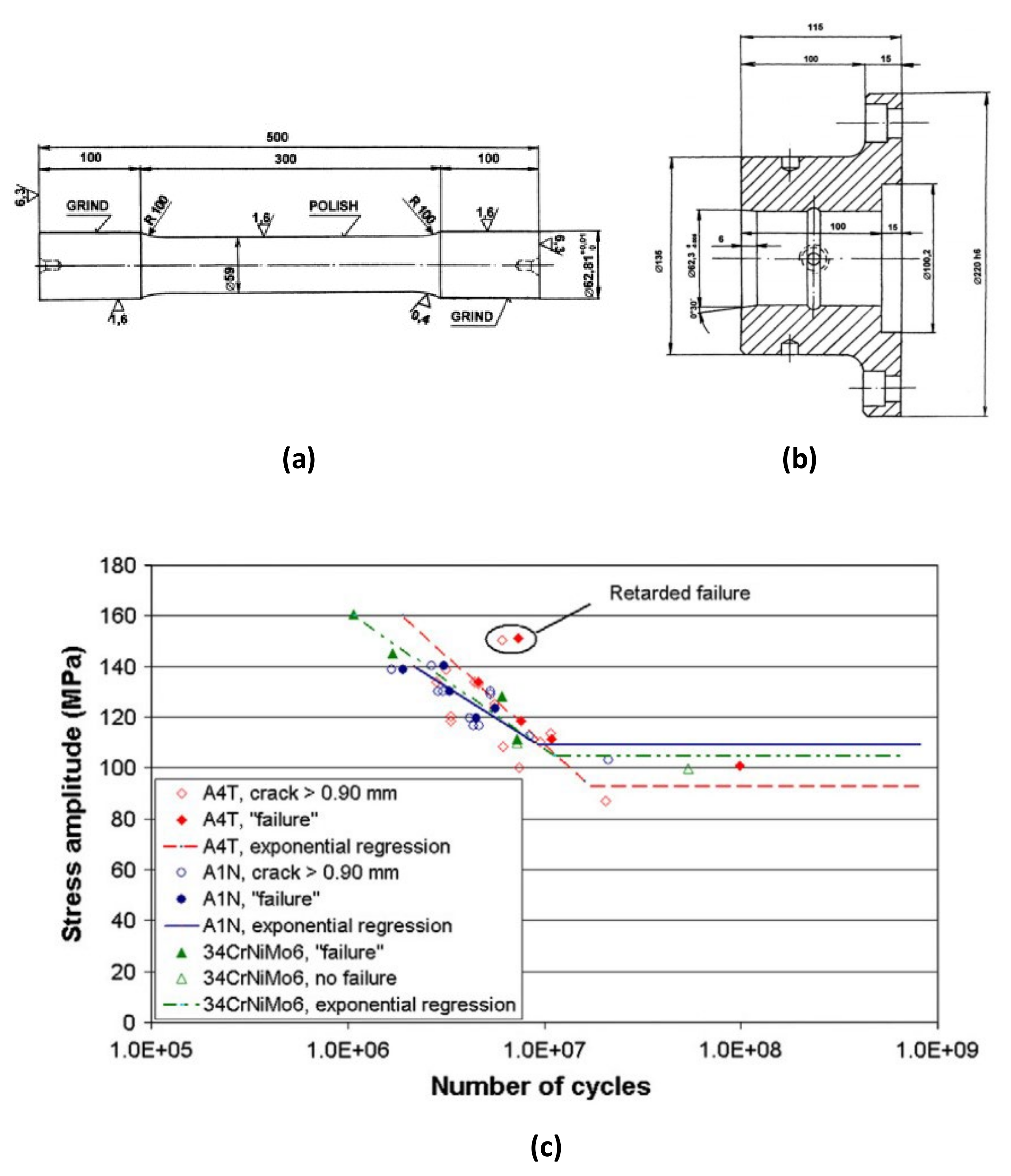
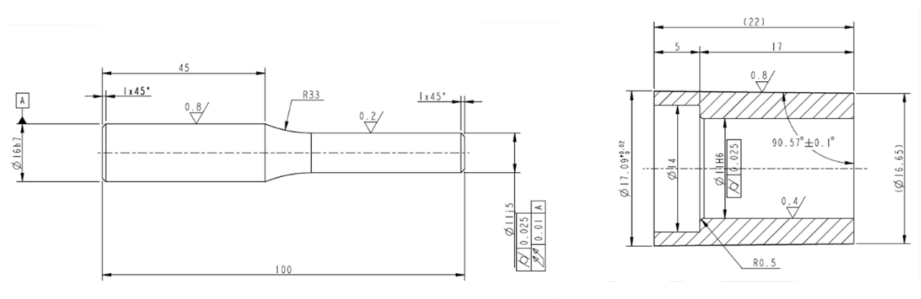
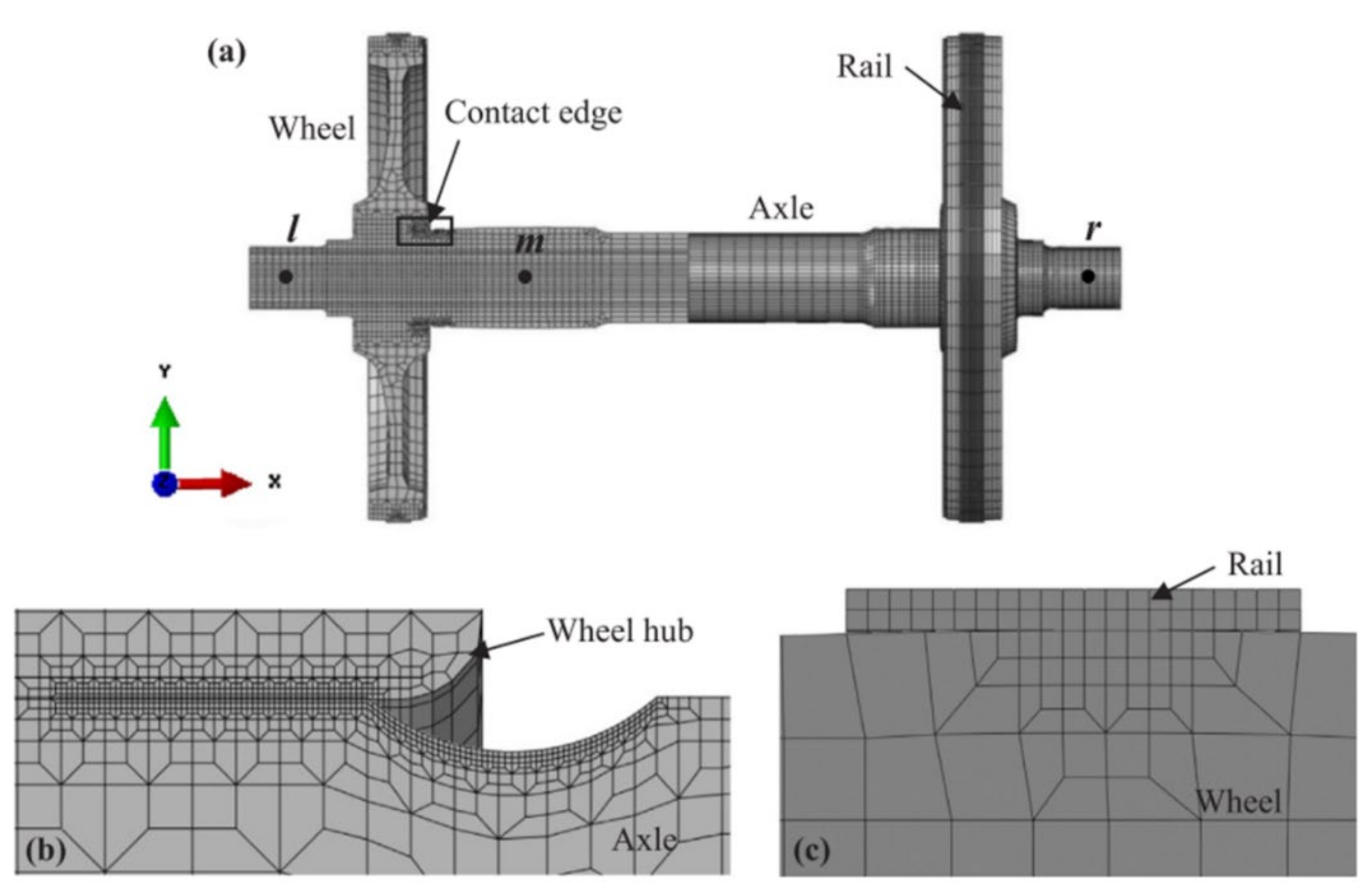
2. Press Fitted Shaft-Hub Joints
Most Significant Results
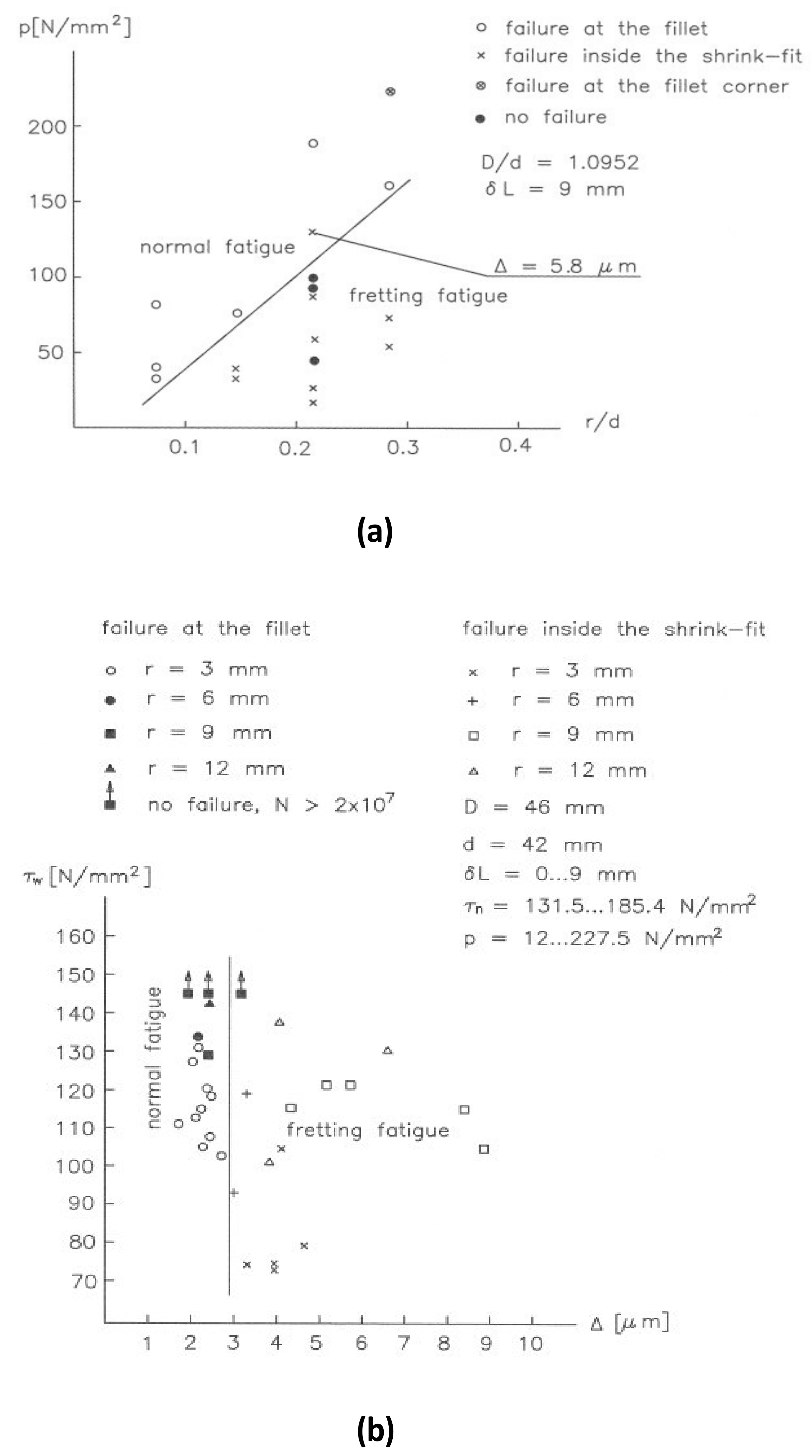
- In fretting conditions, cracks develop near the edge of the contact area, corresponding to the peak contact stress. However, if fretting wear occurs, cracks have been reported to initiate at the inner surface of contact area because of peak stresses occurring at the edge of the wear scar. At the same time, fretting crack initiation at the contact edge is significantly reduced because of the cracks getting ground off;
- A stress relief groove and, possibly, a hub overlap, increases fretting fatigue life. Mixed results have been reported about the influence of the groove radius. More experimental results are needed in order to define the benefits or disadvantages of increasing or decreasing the groove radius;
- It was reported that no significant increase in fatigue strength under press fitting can be expected for high strength steels;
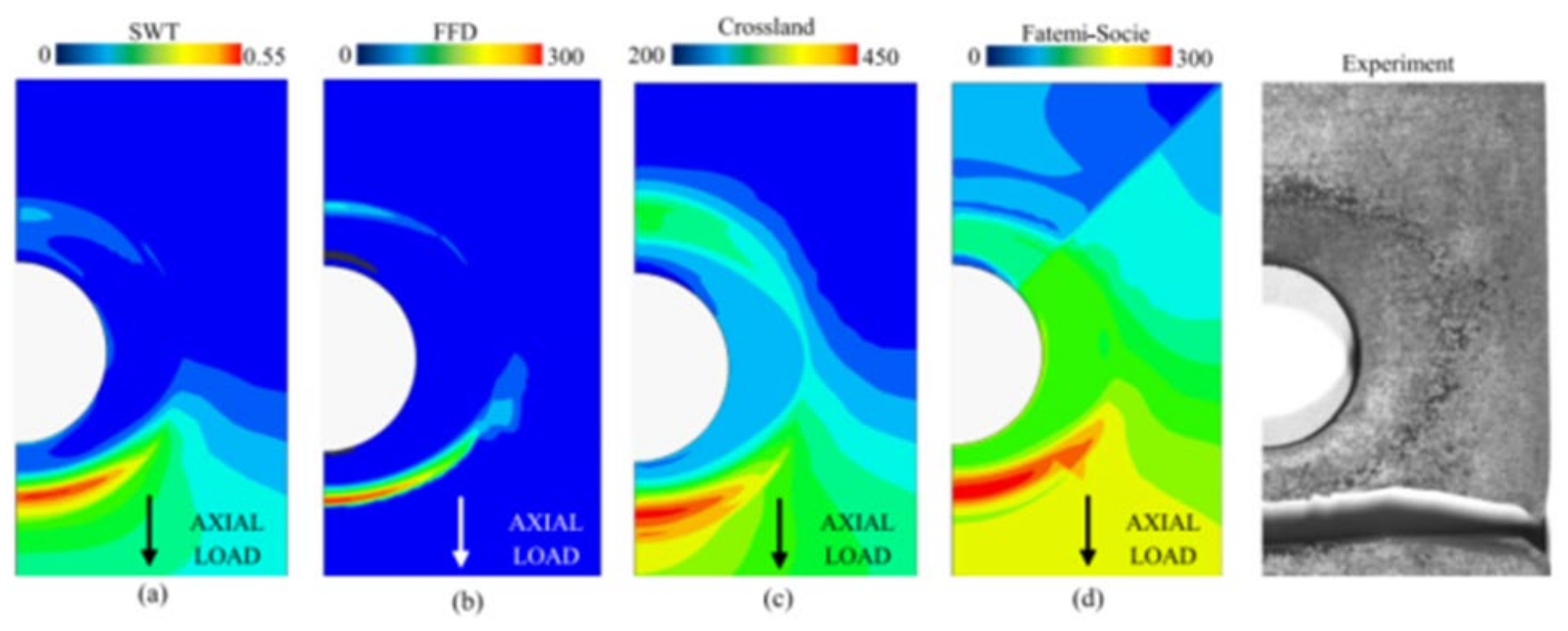
- Use of fretting fatigue criteria such as the SWT and the FS criterion was found to be useful to identify the crack nucleation location. More research is needed in order to assess the use of these parameters;
- Linear elastic fracture mechanics (LEFM) and TPP numerical routine proved to be efficient tools for the evaluation of the crack growth life.
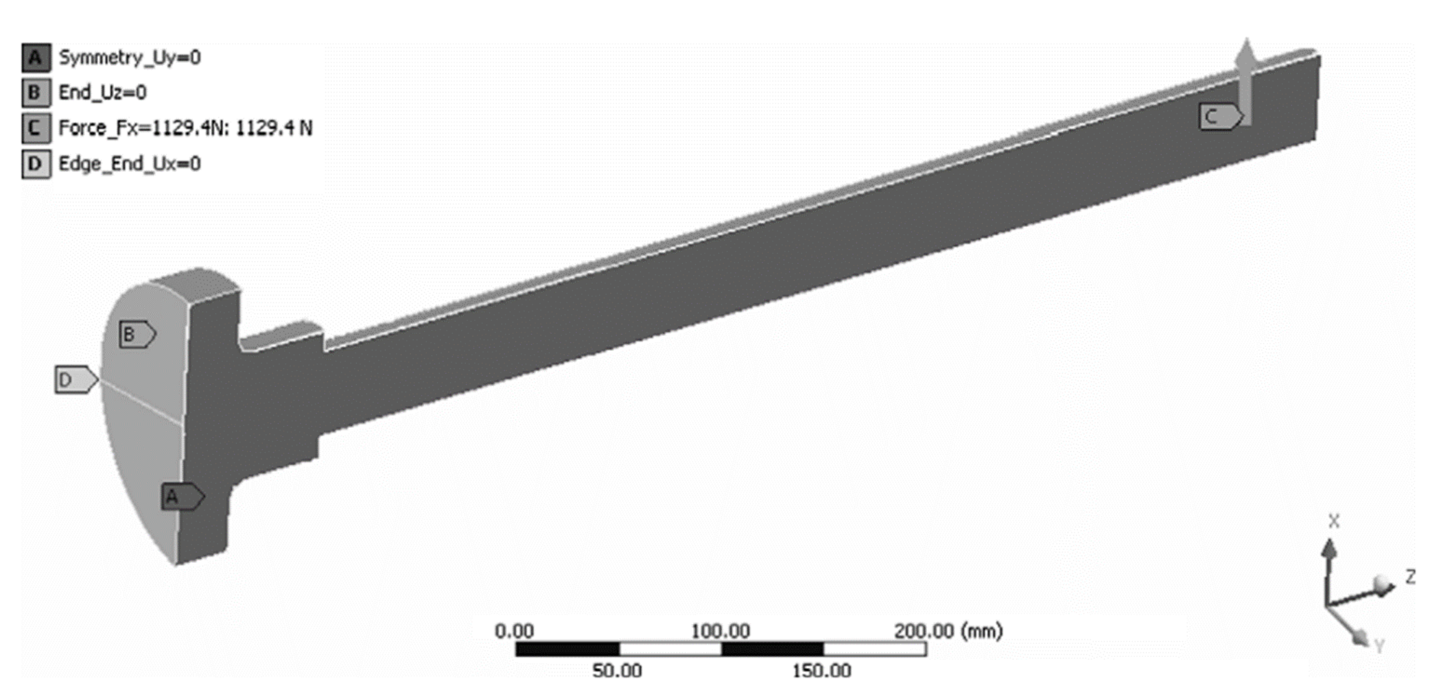
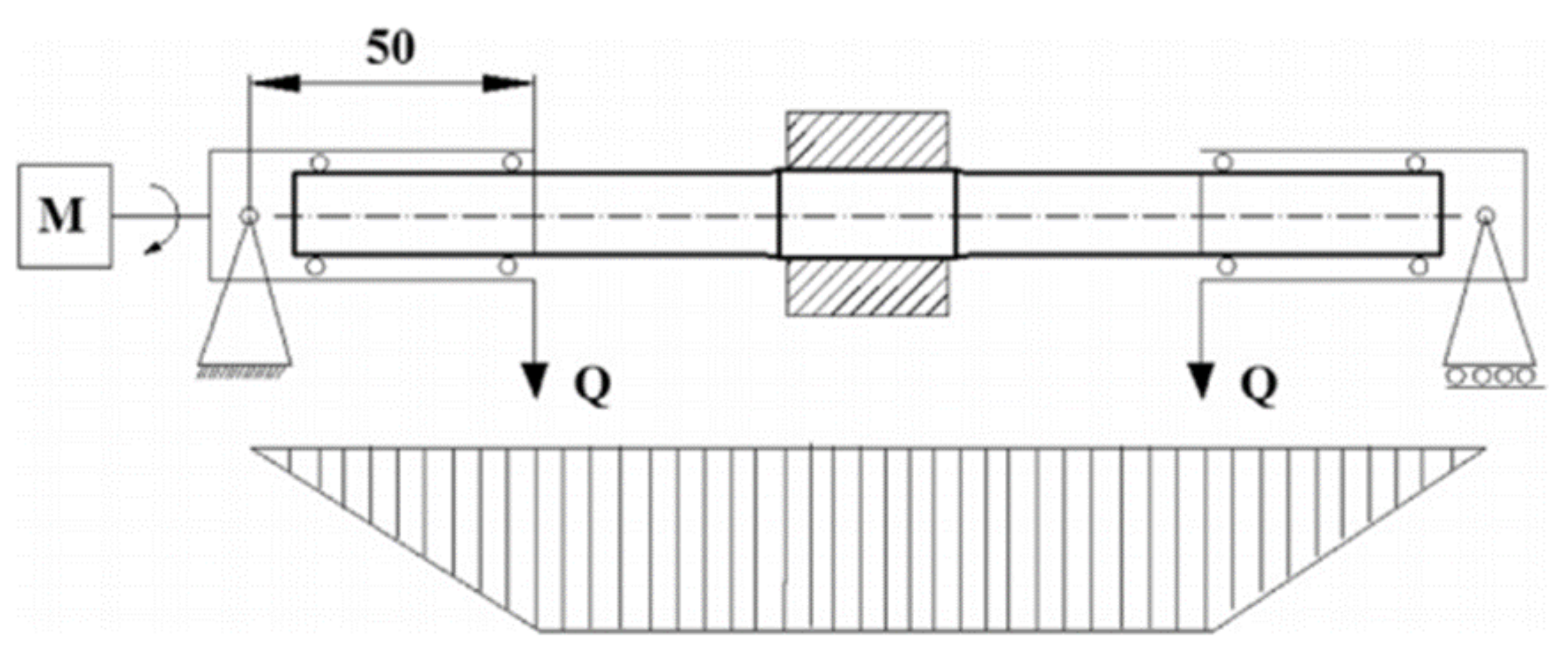
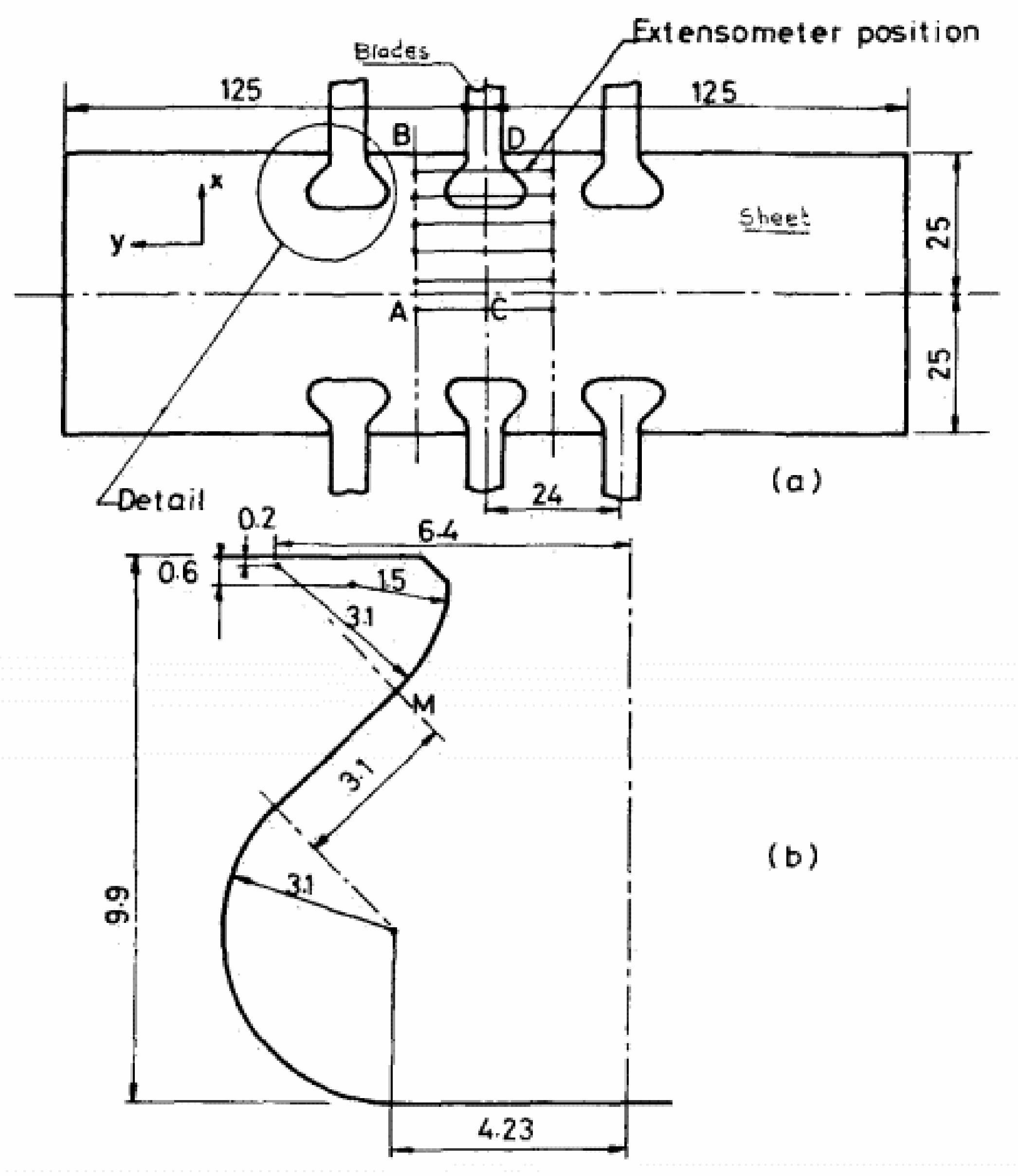
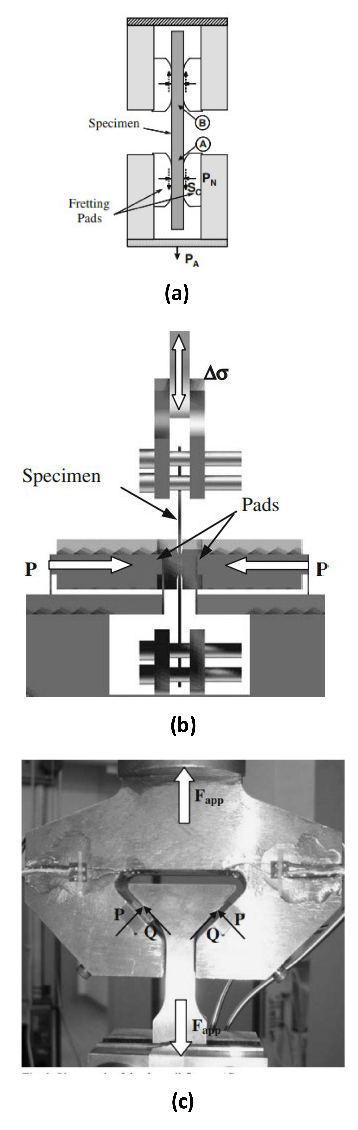
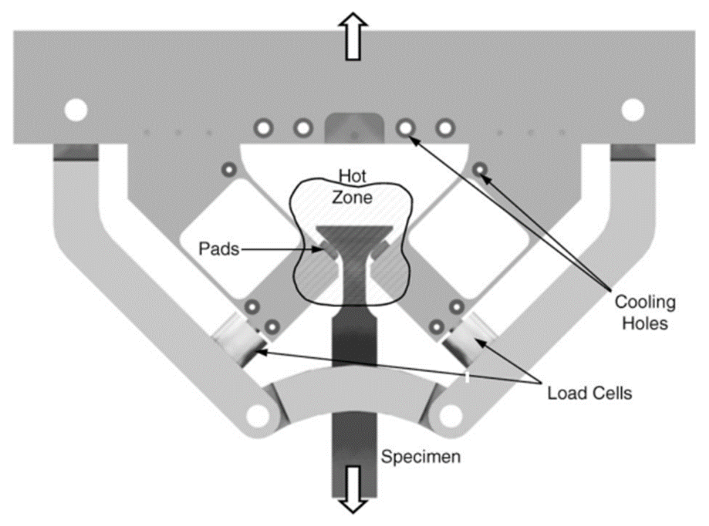
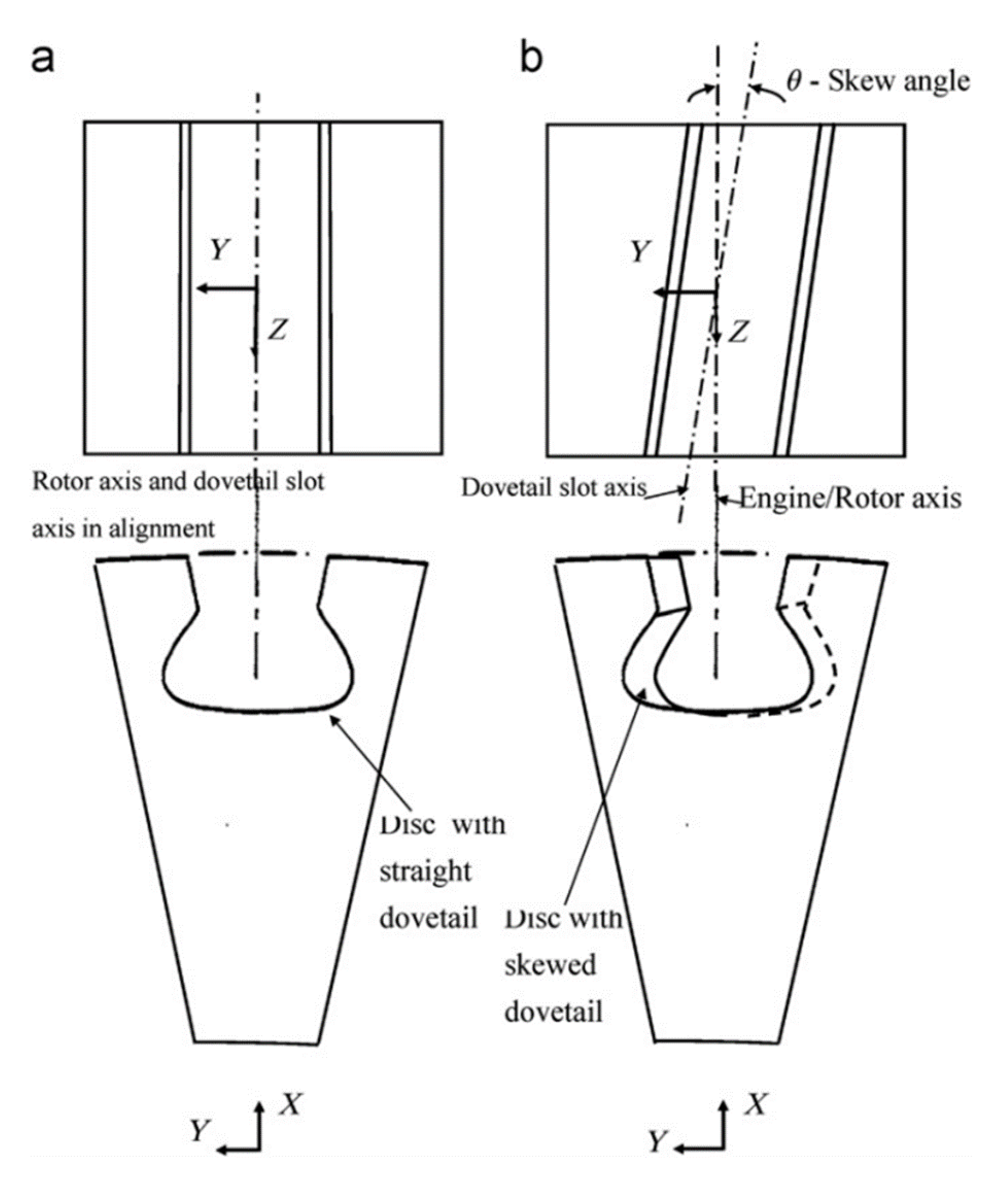
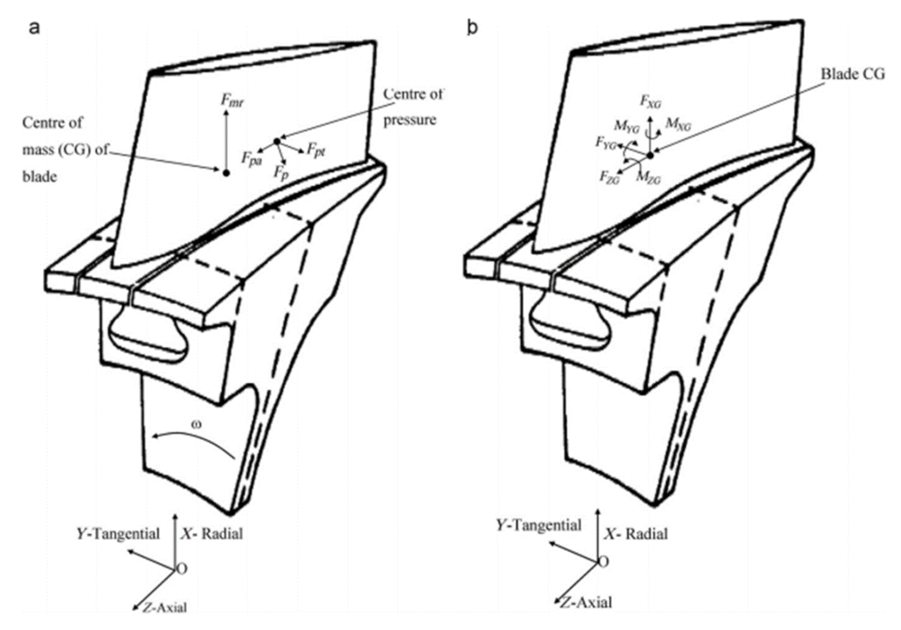
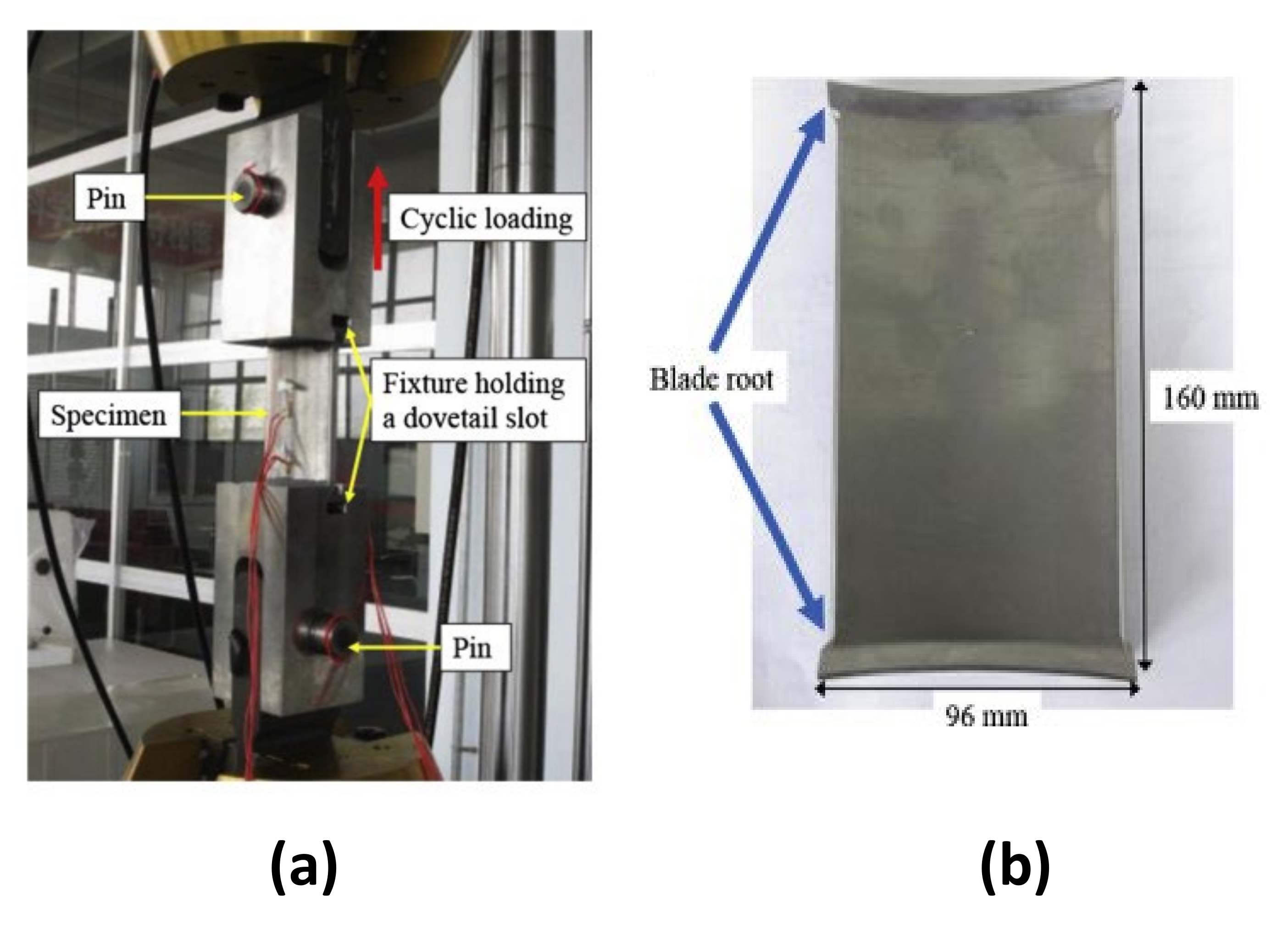
3. Dovetail Joints
- Increasing the sheet loading increased the width, roughness and depth of the fretted region;
- For equal condition of loading and same material, fretting reduced fatigue life;
- For equal condition of loading and material, frequency did not affect the fretting phenomenon.

- a rough correlation between the SWT parameter and contact damage appeared to exist;
- contact stress values appeared to be strongly dependent on the coefficient of friction;
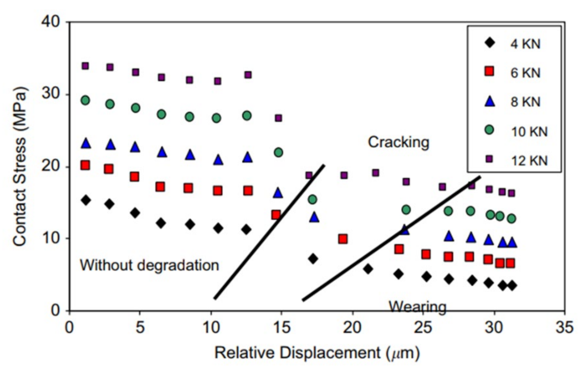
- the stress gradient died out at approximately the same depth for all gradients. This is significant because if this occurs for a wide range of geometries and frictional values, the bulk contact stress can be used to determine the likelihood of crack growth, given that contact stresses will initiate a crack to that depth [75].
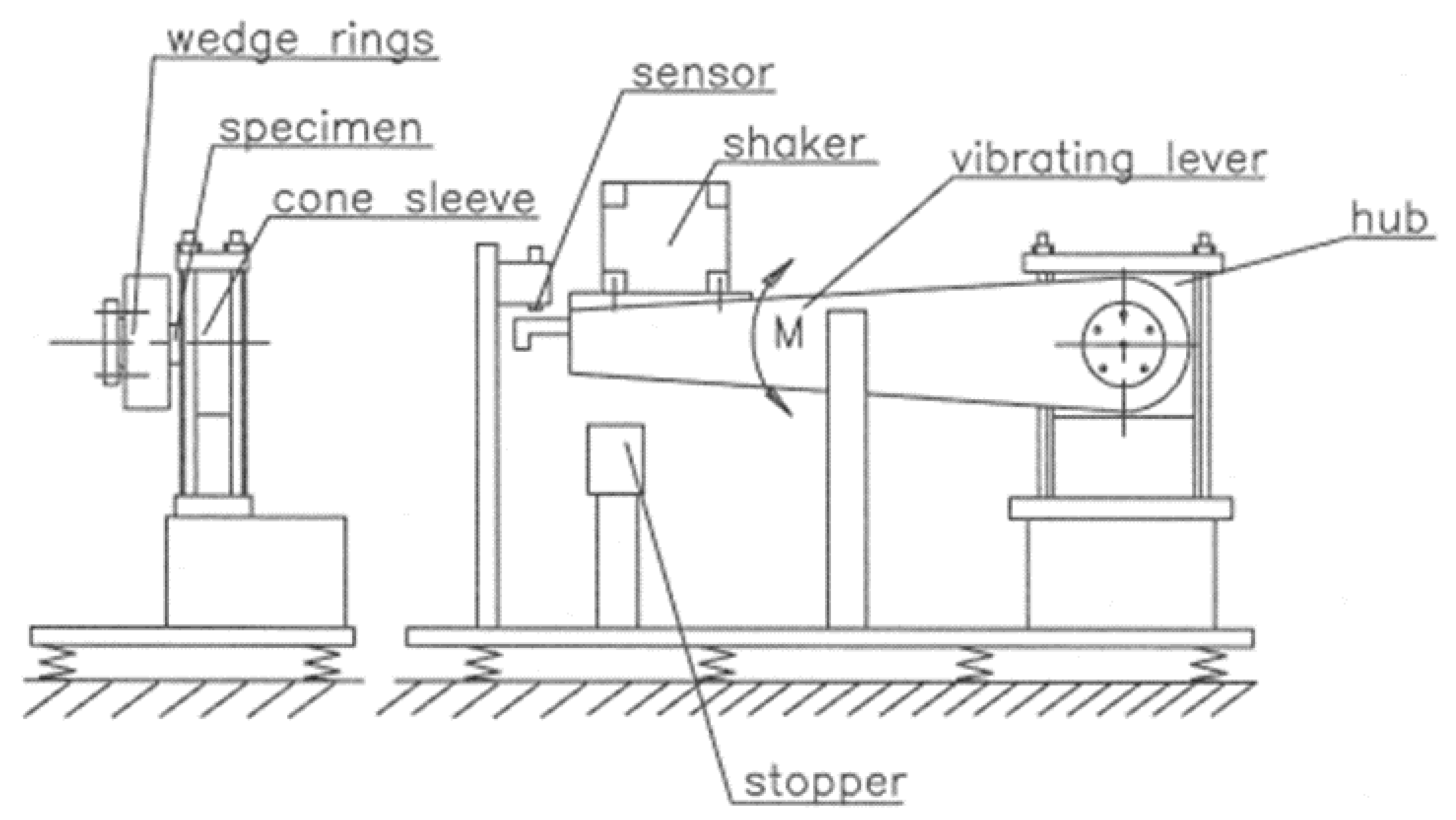
- two load cells in order to be able to directly measure the contact forces applied to the specimen;
- the heating elements capable of simulating the temperature conditions in the attachment region of the turbine rotor.

- Summation approach: this approach considered the summation of the FFDP evaluated for two slip directions;
- Maximum principal-shear stress: this approach considered the use of maximum principal stress in place of and the replacement of shear stress with maximum shear stress considering all the stress components. The formula would then become:
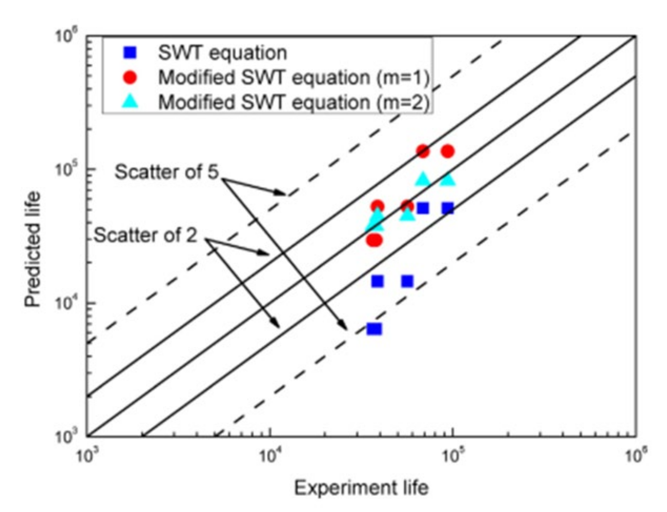
- traditional SWT parameter ( where is the maximum normal stress in one cycle on the critical plane and is the normal strain amplitude on the critical plane [50]);
- averaging SWT introducing a weight function since it was reported that crack initiation parameters (such as SWT) provided conservative life predictions in the case of high stress gradients. The averaged SWT parameter is expressed as follows:
Most Significant Results
- Different dovetail skew angles were not found to substantially influence fretting fatigue life;
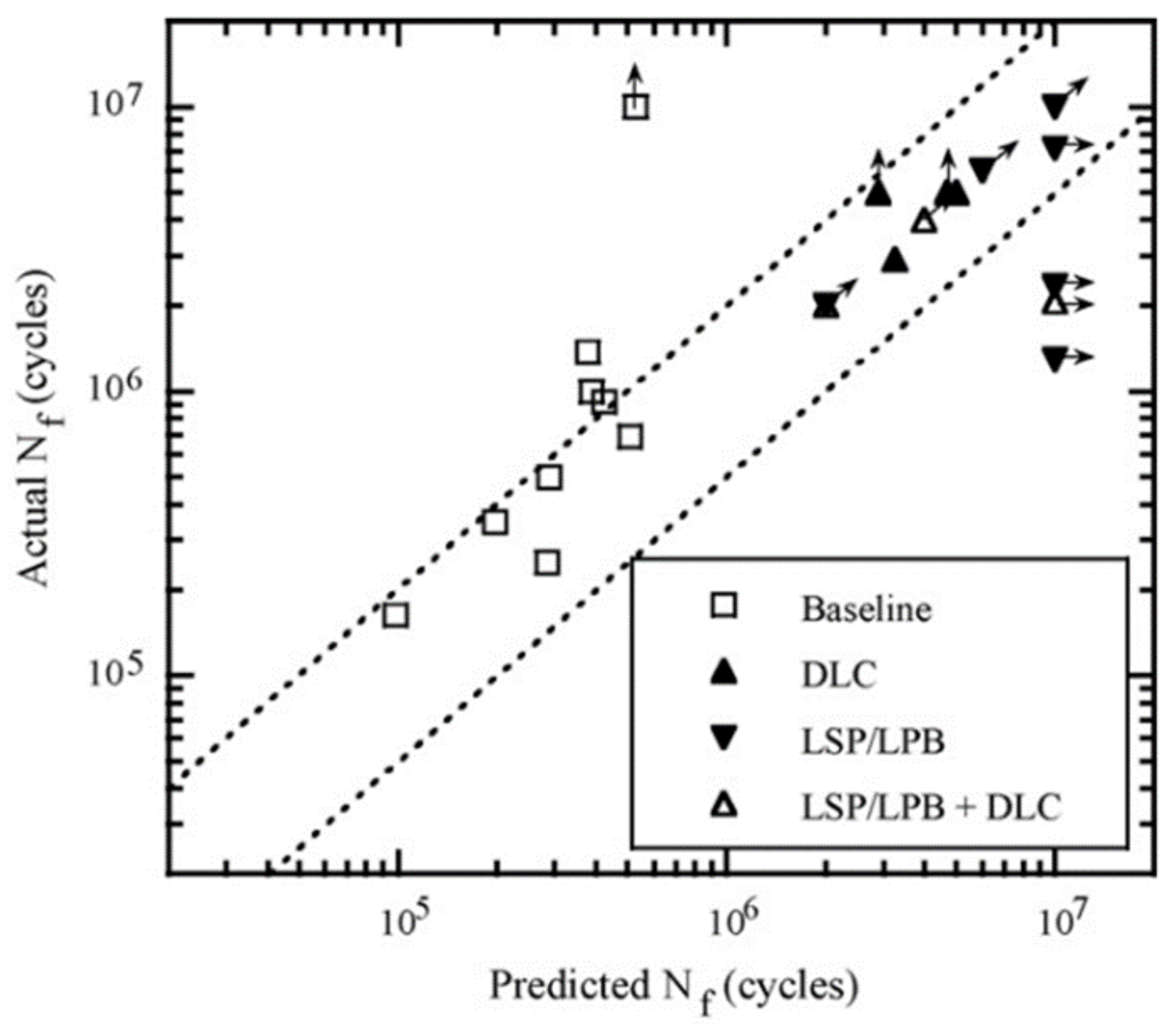
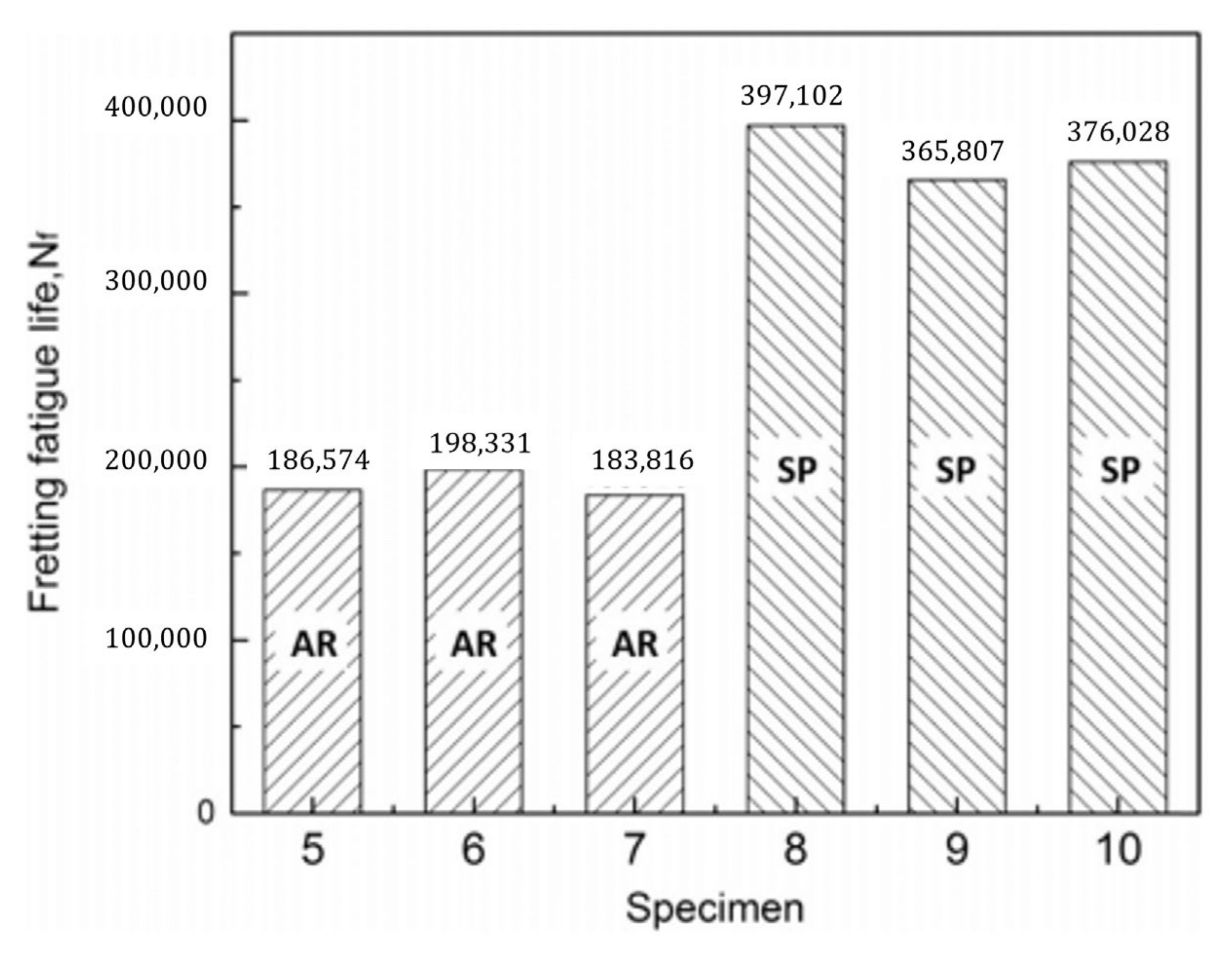
- Coatings and shot-peening were found to be effective for raising the resistance to fretting fatigue crack initiation. More types of coatings should be tested in order to give better guidelines;
- Analytical studies indicate that smaller punch radiuses are expected to improve fretting fatigue behaviour, but it was highlighted that the effect of vanishing small radiuses is unknown and therefore that research on the matter is needed;
- The Ruiz criterion successfully located the initiation location, but it was highlighted that the parameters used by Ruiz do not have a direct physical interpretation and, therefore, are not generally suitable for quantitative analyses. Other parameters have been mathematically developed, although validation on different geometries is currently lacking;
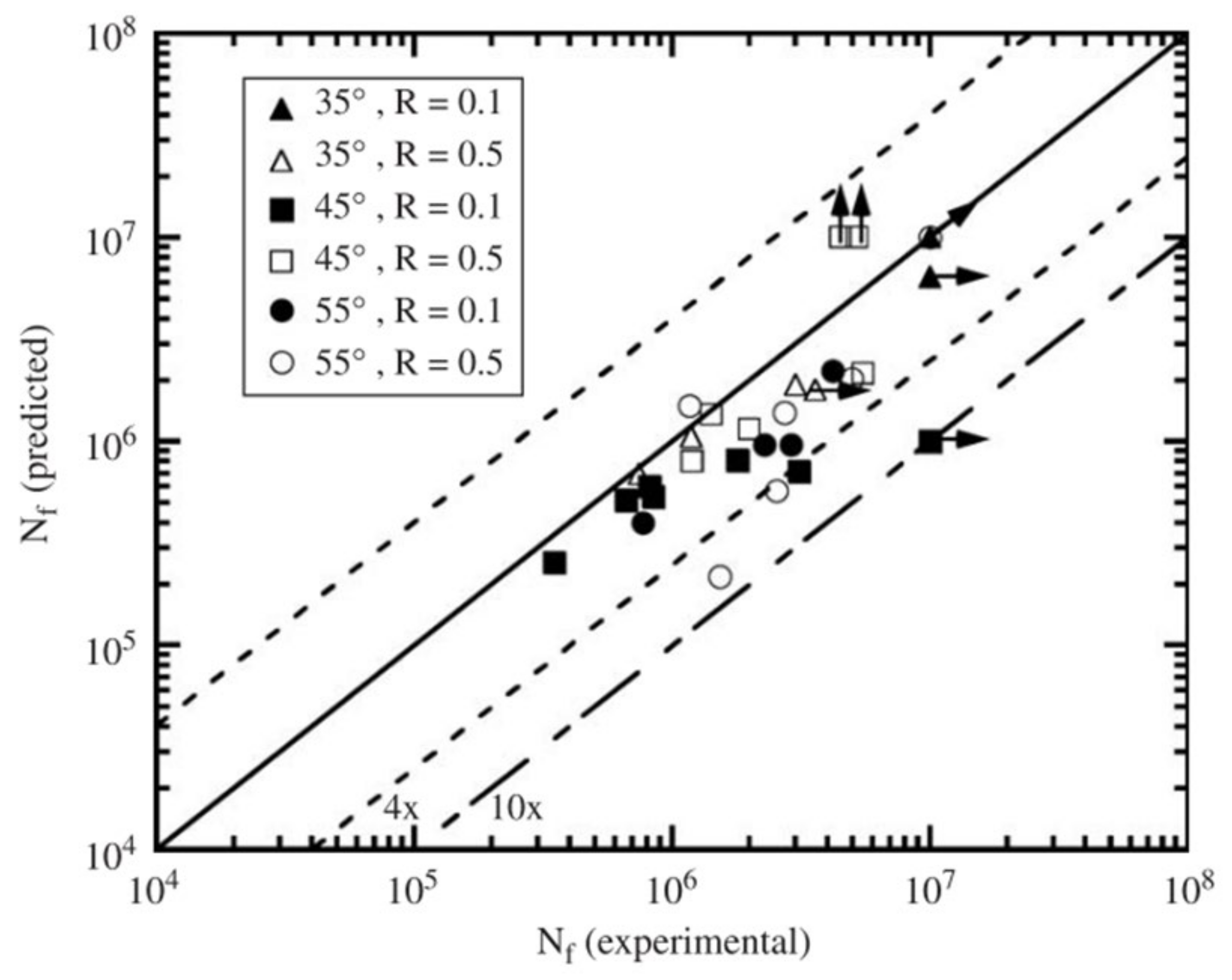
- The use of the SWT criterion, especially in its weighted variant [86] and modified variant [91] were found to be able to successfully predict crack nucleation site on specimens. The modified variants also successfully predicted the fretting fatigue life of specimens. However, it was highlighted that these approaches must be further tested under different loading conditions in order to be fully validated;
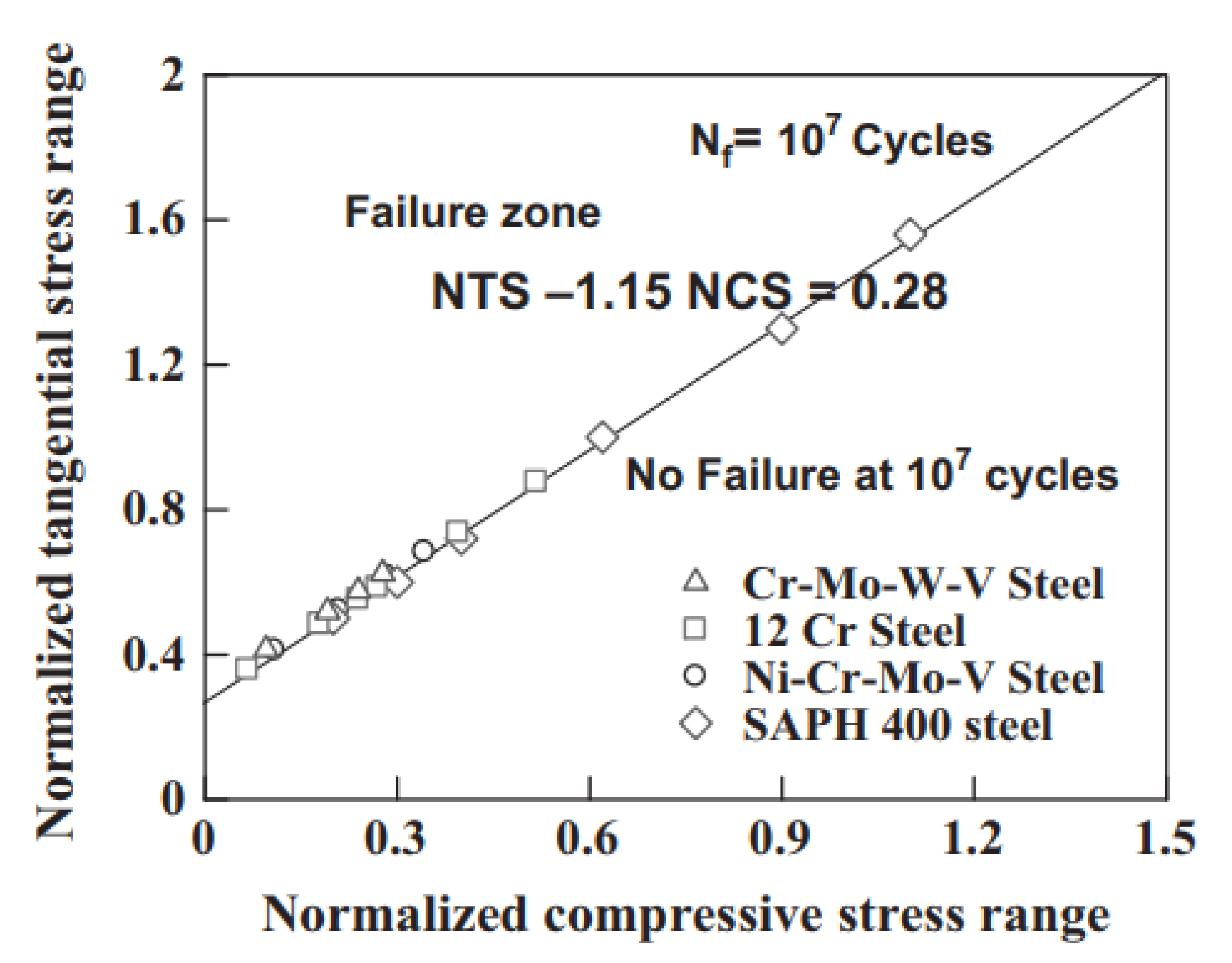
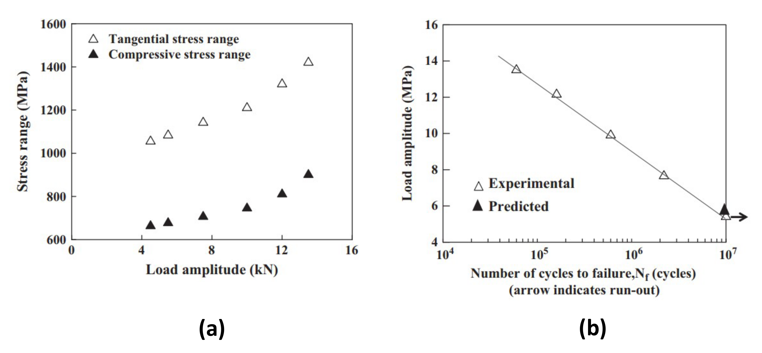
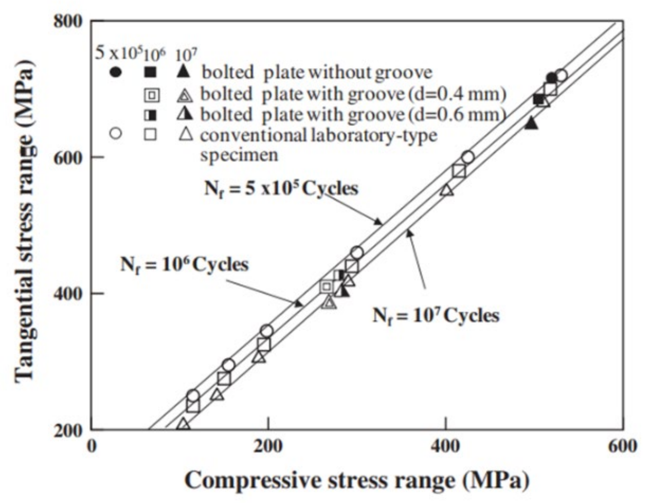
- The TSR-CSR diagram was found to be a useful tool for the prediction of fretting fatigue failure, even though it is different for every material, and so it has to be retrieved for each material tested or used;
- The linear elastic fracture mechanics (LEFM) approach was also found to be generally a good tool for the evaluation and prediction of crack growth lives;
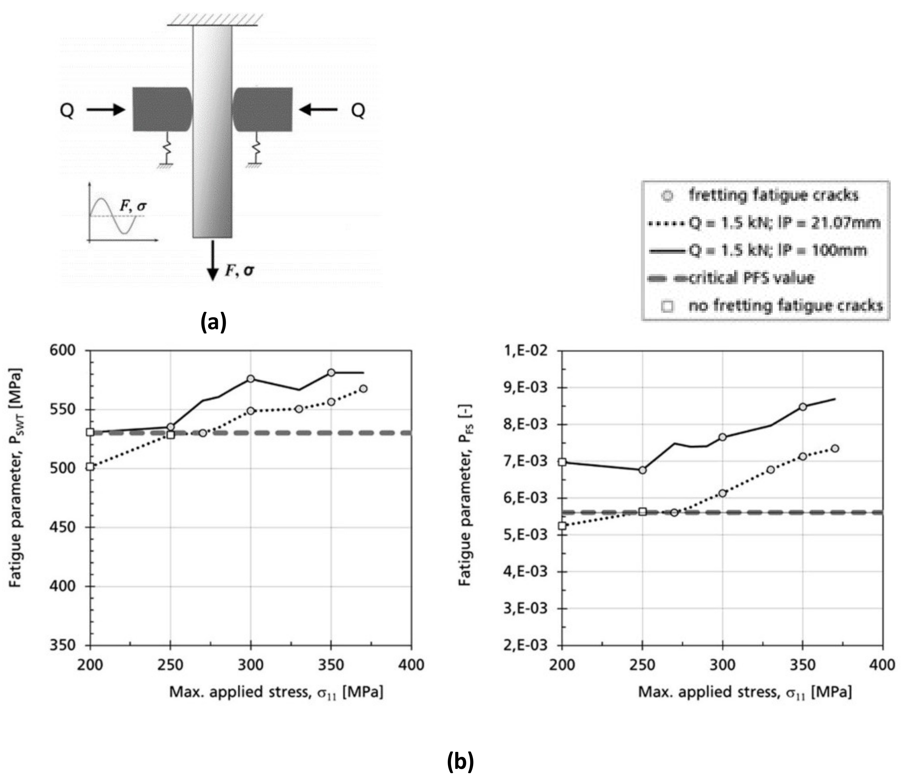
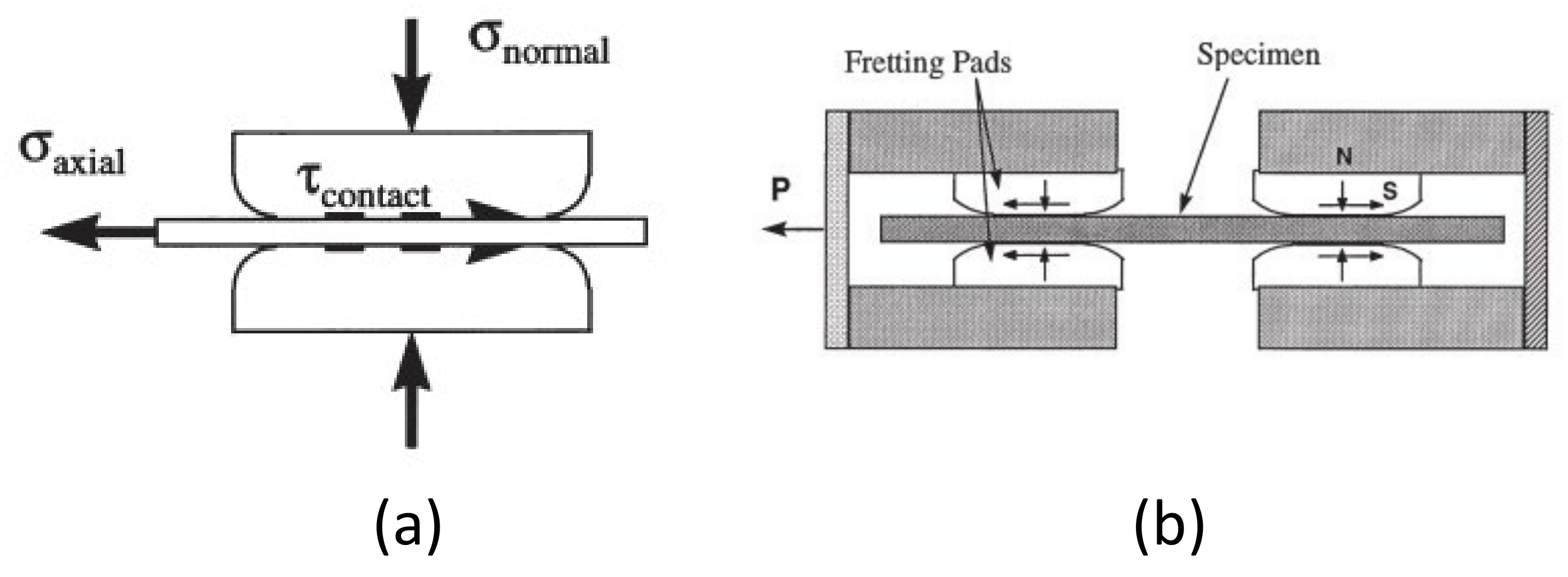
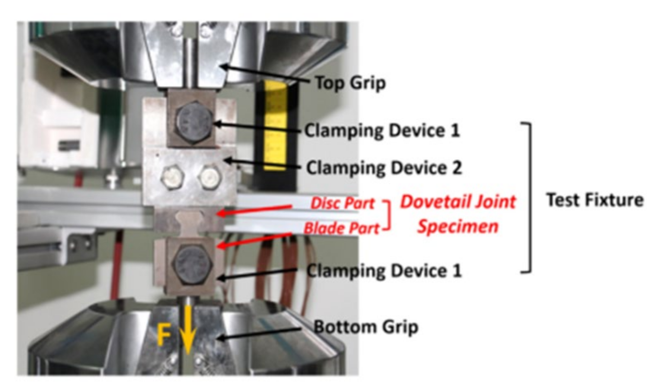
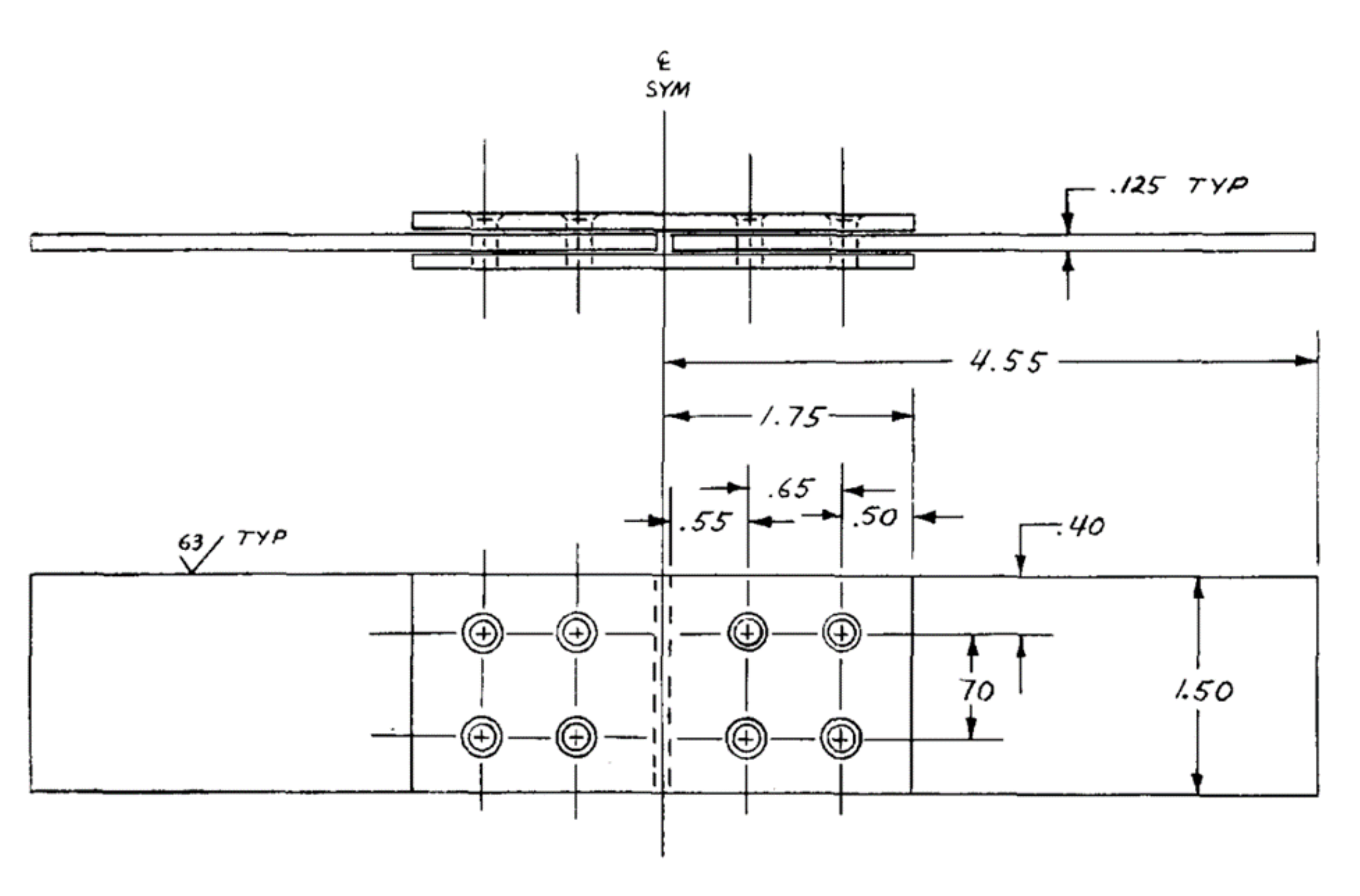
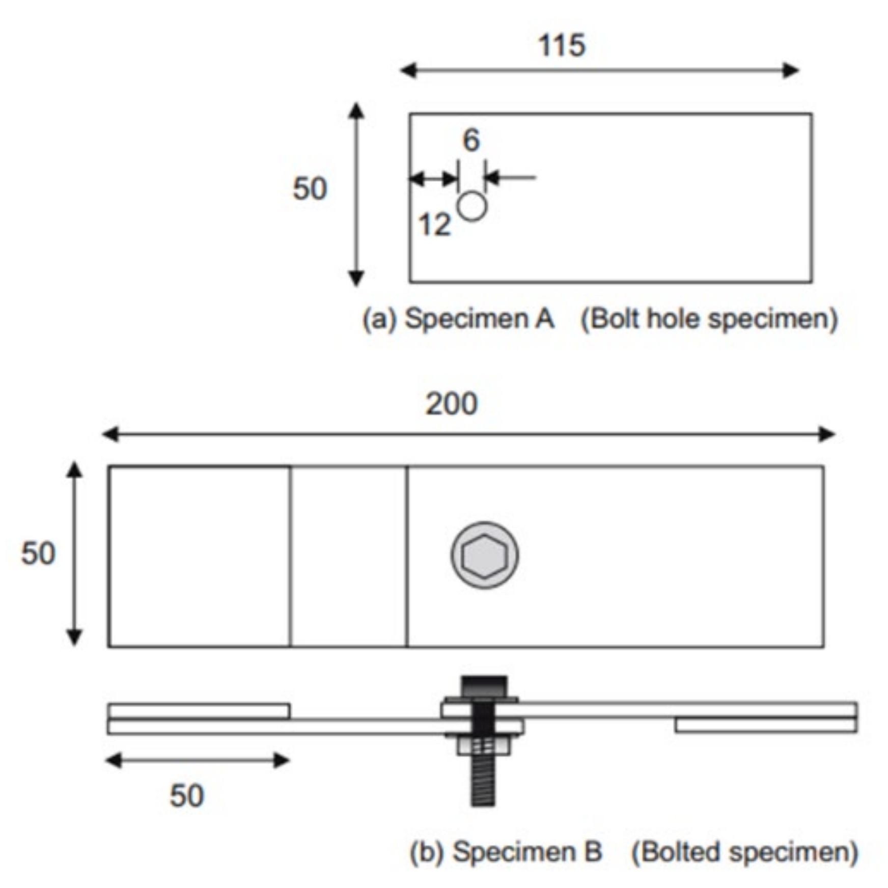
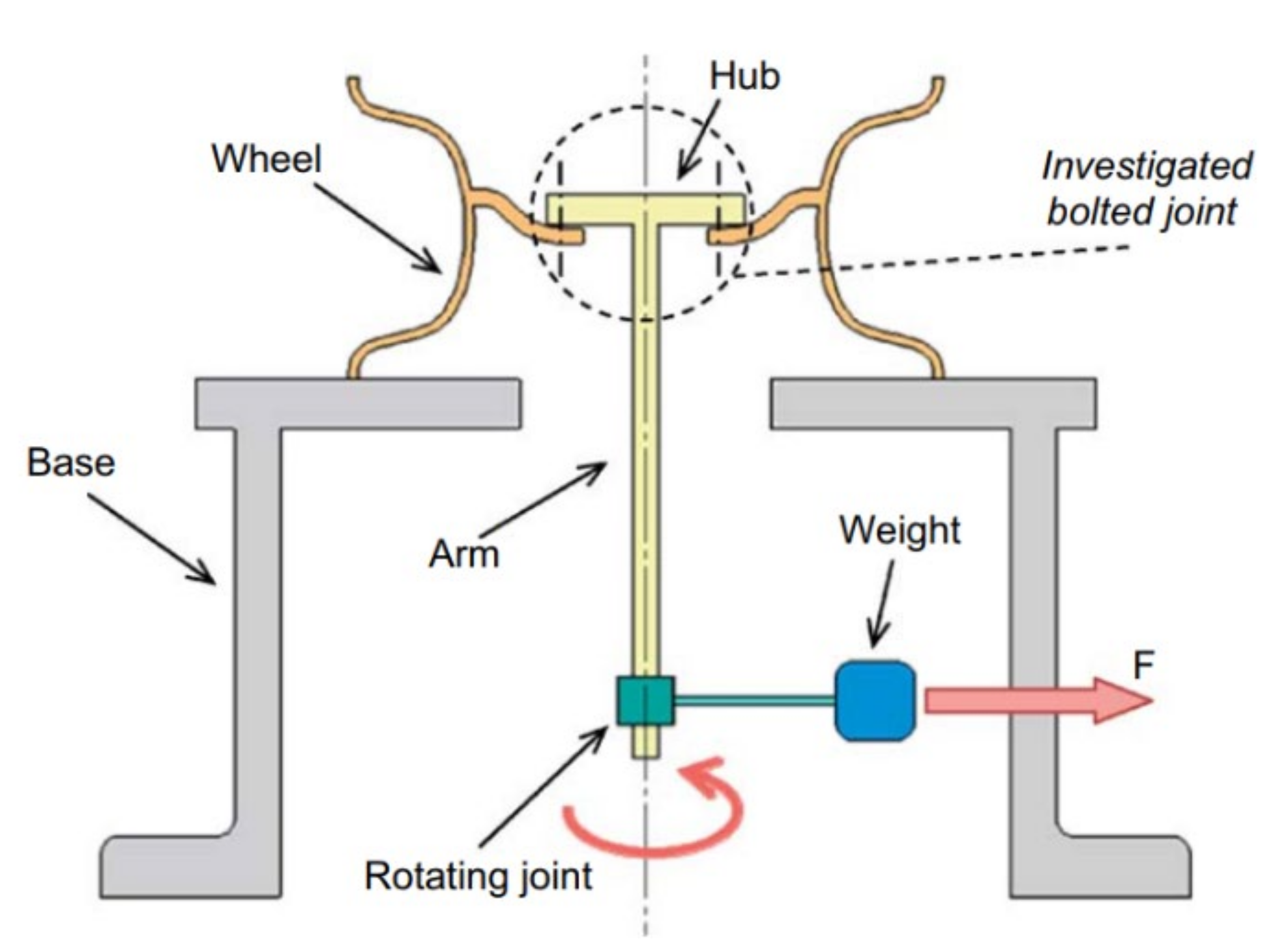
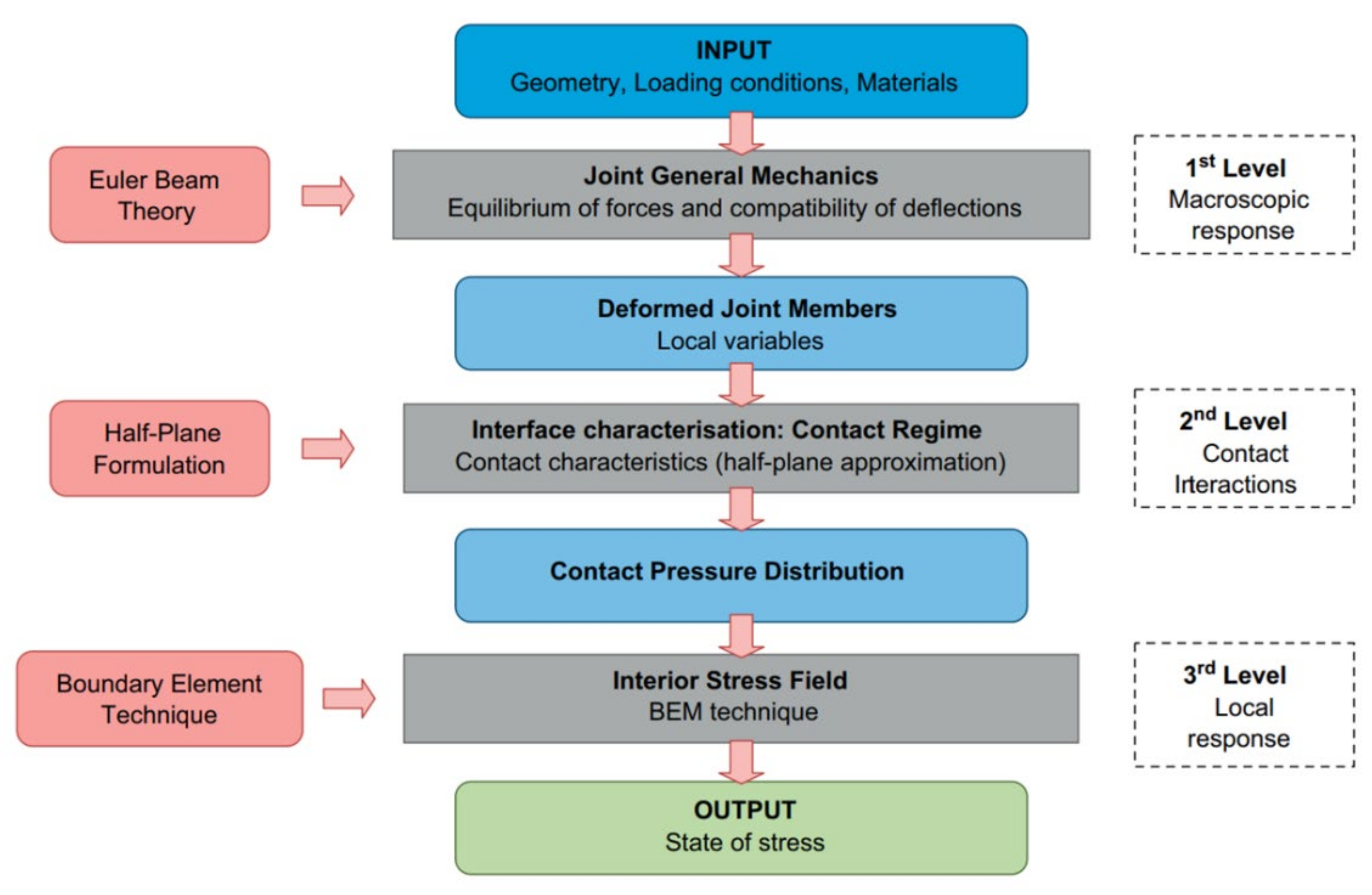
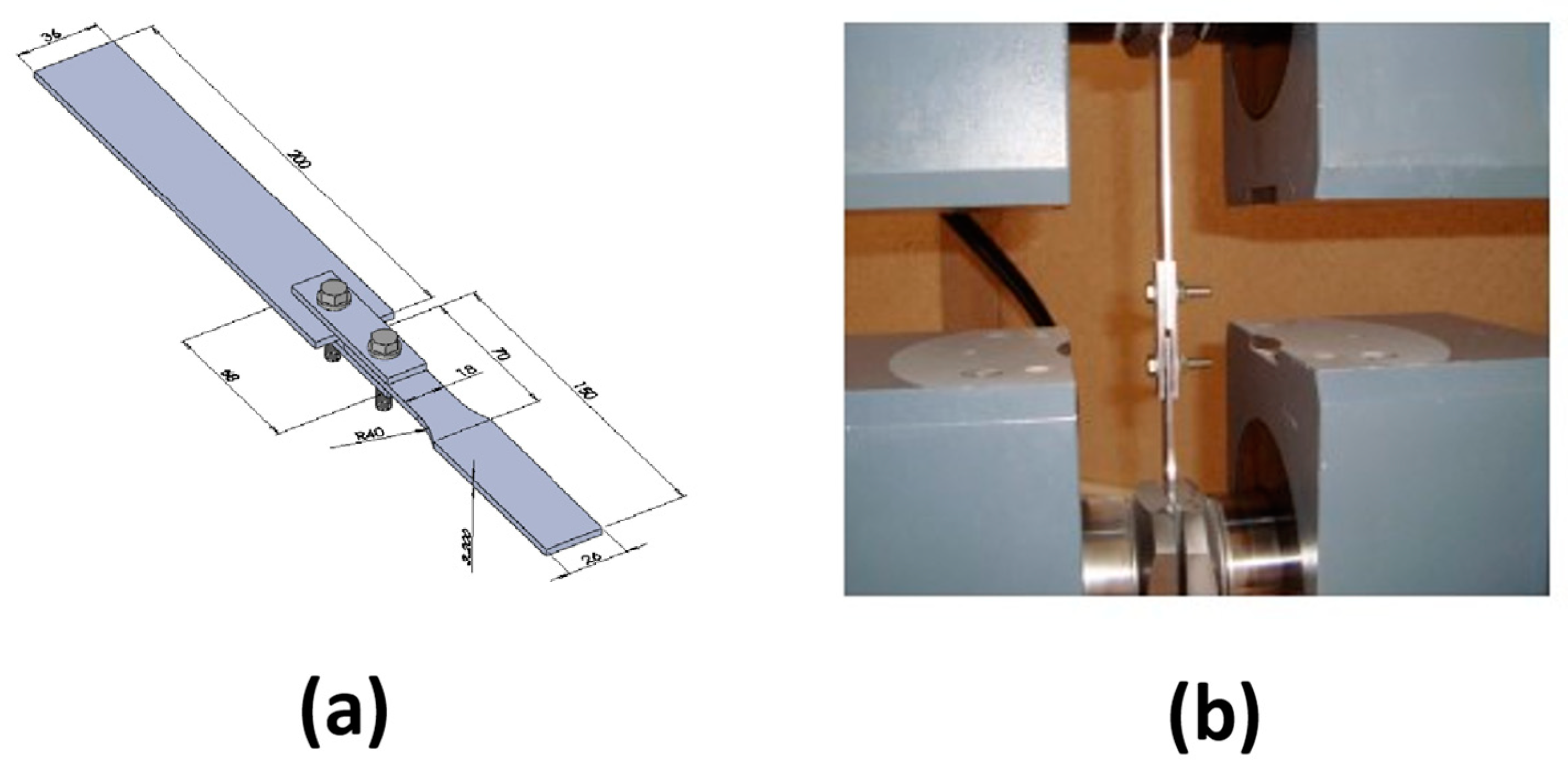
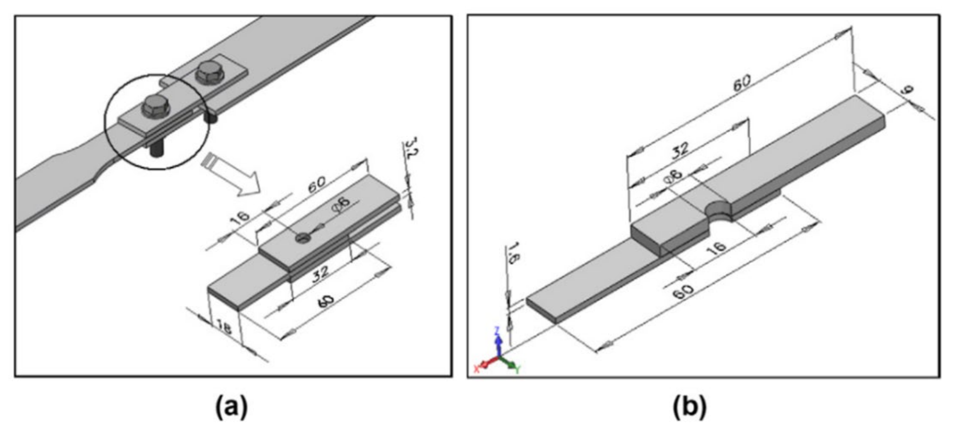
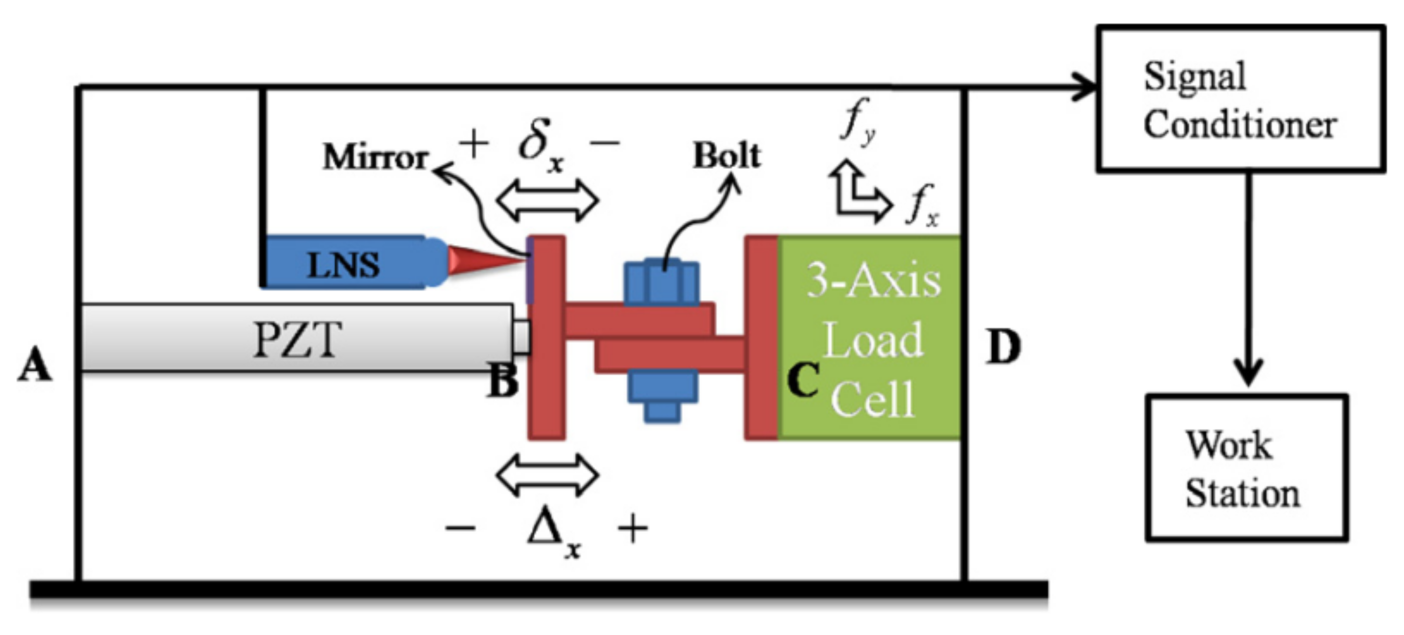
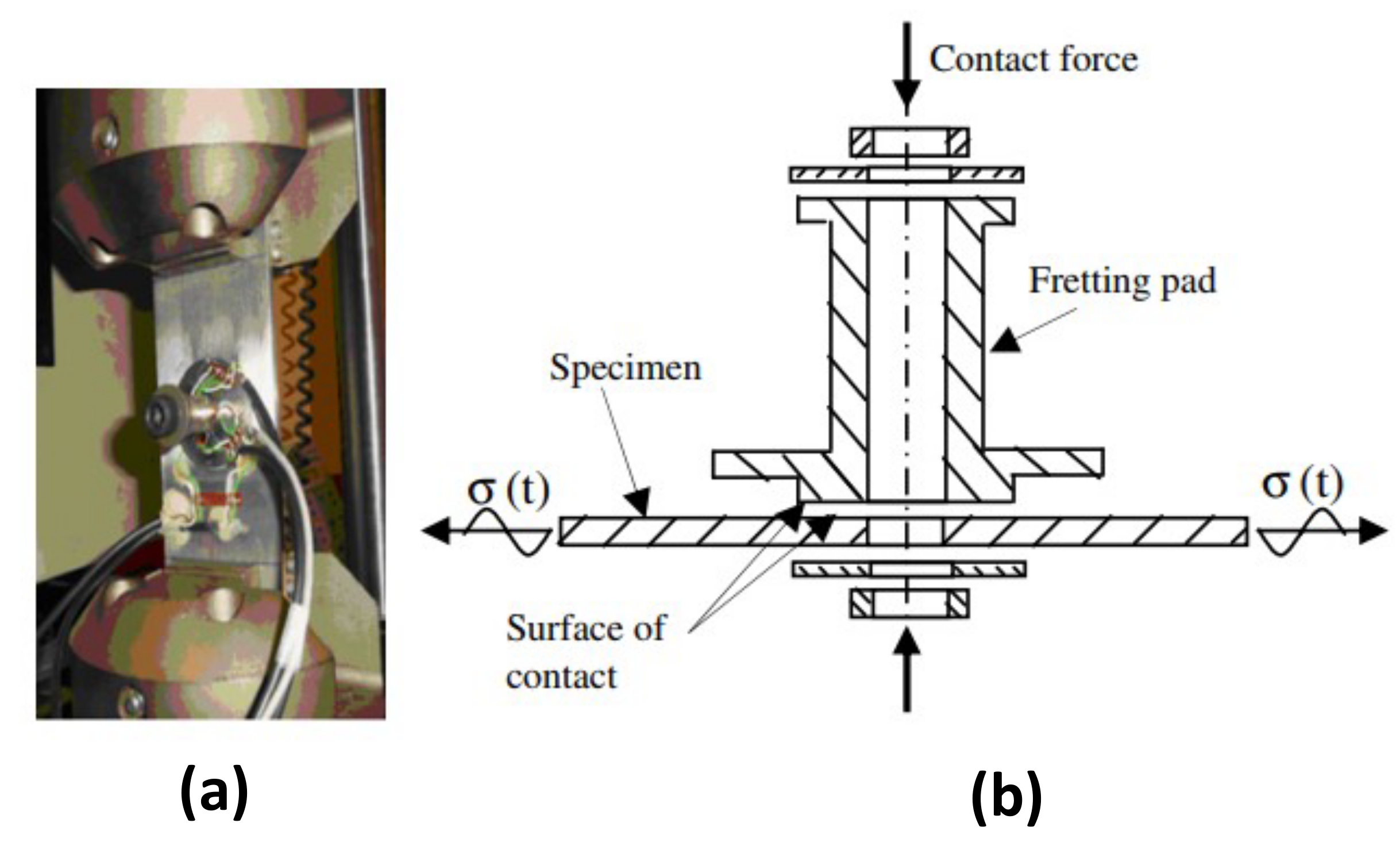
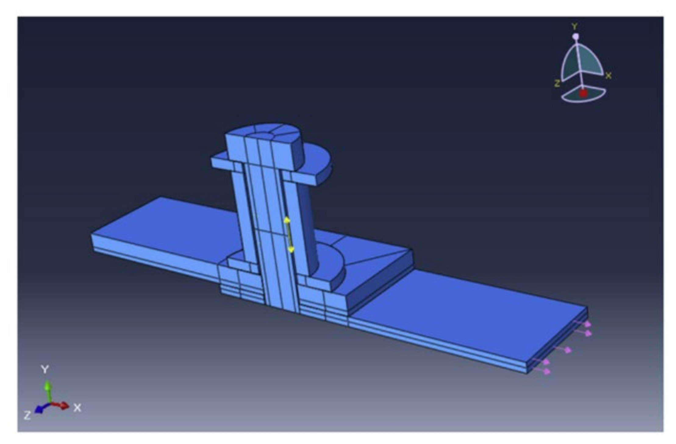
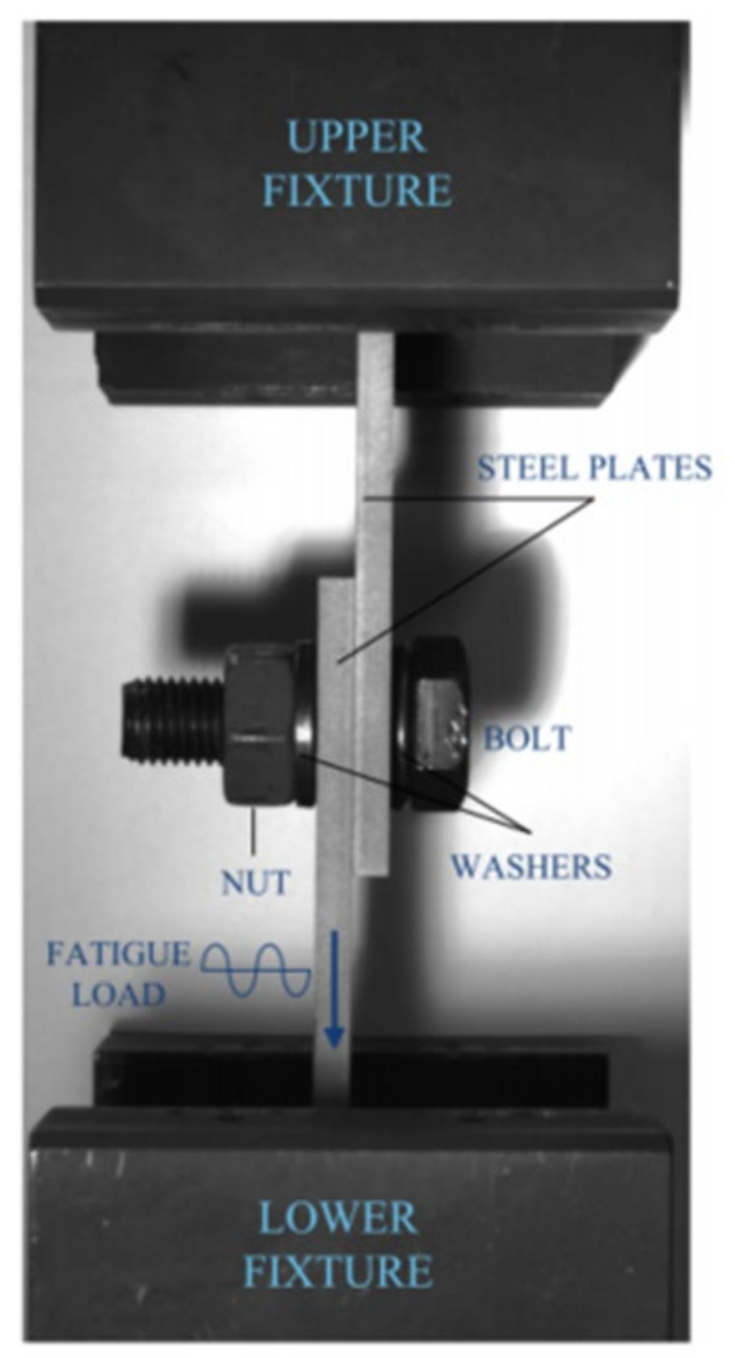
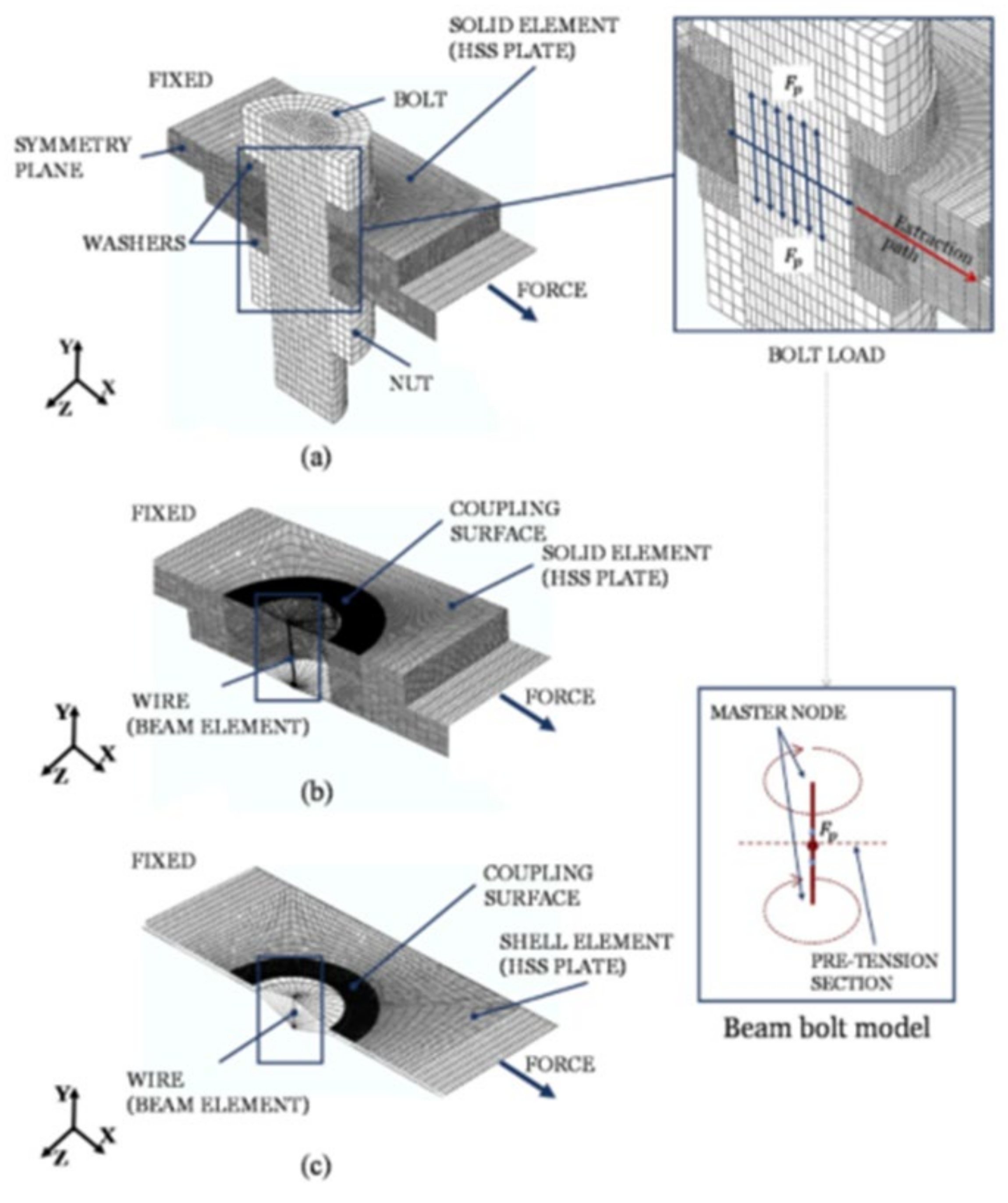
4. Bolted Joints
- Evaluation of the general response of the bolted joint when rotating bending and other remote loading conditions are applied (macroscopic response—level 1);
- Evaluation of the contact traction at the interface between the parts in contact (contact interactions and interface characterisation—level 2);
- Evaluation of the full stress field near the critical damage areas (stress field or local response—level 3).


Most Significant Results
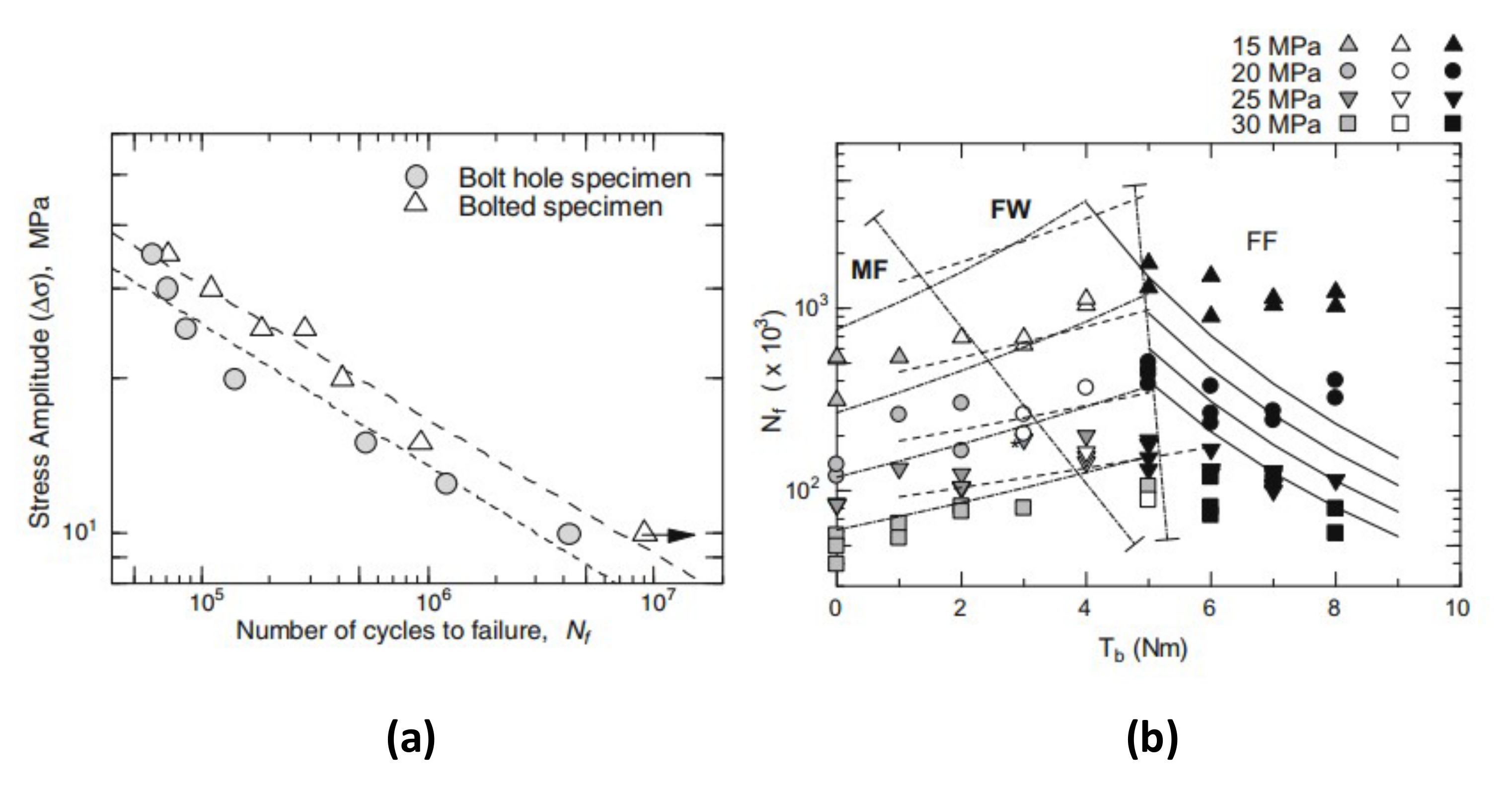
- In fretting contact conditions, increasing the tightening torque is generally a good approach for improving fretting fatigue life. This is explicable with the consequent lowering of sliding happening in the contact area;
- It has also been highlighted that, for low tightening torques, fretting fatigue does not occur. This can be visually explained by means of fretting maps, like the one used by Benhamena et al. [100]. It has been found that for low contact loads, and regardless of high or even very low slipping, fretting fatigue might not occur. For more information about fretting maps, please refer to [108,114,115,116];
- Bonding the mating surfaces does improve fatigue life, but is a limitation affecting the disassembly of the joint;
- Use of fretting fatigue criteria such as the SWT, the FS and the Ruiz criterion was found to be useful to identify the crack nucleation location. More research is needed in order to assess the use of these parameters;
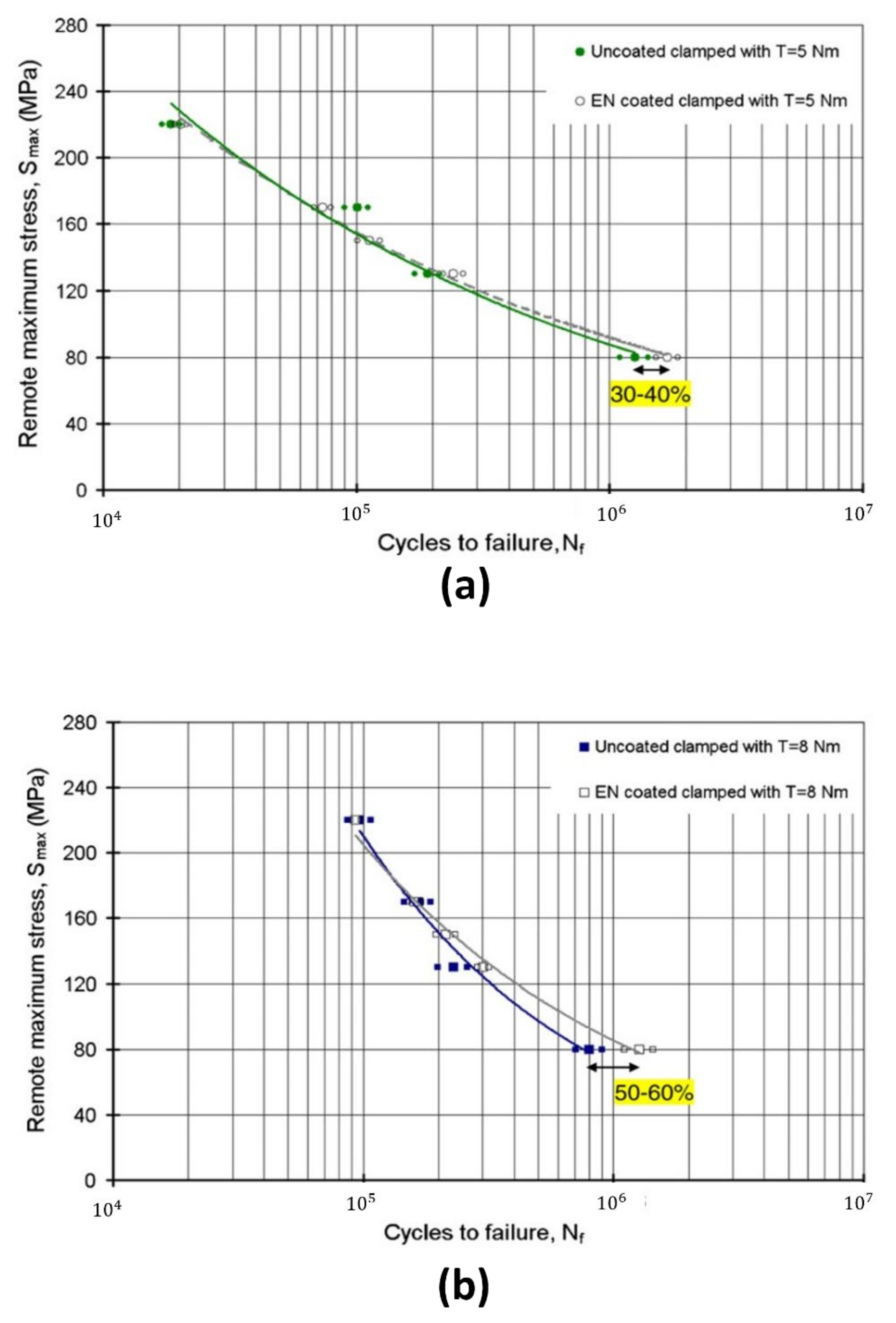
- Applying Ni-P coatings was proven to improve fretting fatigue life;
- Applying lubrication between the contact surfaces has been reported to have mixed results. The results may arise from different initial experimental conditions. More studies need to be carried out, in order to assess more clearly the advantages and disadvantages of the use of lubricants;
- The TSR-CSR diagram was found to be a useful tool for the prediction of fretting fatigue failure also for bolted joints.
5. Conclusions
- Under fretting conditions, cracks develop near the edge of the contact area, corresponding to the peak contact stress. However, if fretting wear occurs, cracks have been reported to initiate at the inner surface of contact area because of peak stresses occurring at the edge of the wear scar. At the same time, fretting crack initiation at the contact edge is significantly reduced because of the cracks getting ground off;
- Relative slip and contact pressure are fundamental parameters that directly influence, together with wear, the local stress–strain contact state. Therefore, evaluating the joint action of these parameters is important for predicting the macroscopic behavior of the joint, as different combinations can lead either to an improvement or a deterioration of fretting fatigue life;
- Multiaxial fatigue parameters used with the critical plane approach (as SWT and FS) appear to be helpful in locating fretting fatigue crack initiation location for all kind of joints. However, the total predicted life is strongly influenced by the choice of the initial crack length, which is arbitrary;
- The TSR-CSR diagram was found to be a useful tool for the prediction of fretting fatigue failure both in dovetail and bolted joints. Research for the application of this criterion on press-fitted shaft/hub joints is lacking, however, and is therefore needed. It must also be highlighted that the TSR-CSR diagram is different for each material and so it must be retrieved for any new, used or tested material;
- The application of the linear elastic fracture mechanics (LEFM) approach was also found to be optimal for the evaluation and prediction of crack growth lives for all the joints covered in this review;
- Coatings and shot-peening were found to be effective for raising the resistance to fretting fatigue crack initiation. More types of coatings should be tested, however, since the results refer to a very limited group of treatments; fretting maps are also very useful and easy to read tools that can give a visual and immediate description of the fretting regime (or lack of) occurring in the joint.
Author Contributions
Funding
Institutional Review Board Statement
Informed Consent Statement
Data Availability Statement
Conflicts of Interest
References
- Hurricks, P.L. The Mechanism of Fretting—A Review. Wear 1970, 15, 389–409. [Google Scholar] [CrossRef]
- Szolwinski, M.P.; Farris, T.N. Mechanics of Fretting Fatigue Crack Formation. Wear 1996, 198, 93–107. [Google Scholar] [CrossRef]
- Nishioka, K.; Hirakawa, K. Fundamental Investigations of Fretting Fatigue: Part 3, Some Phenomena and Mechanisms of Surface Crack. Bull. JSME 1969, 12, 397–407. [Google Scholar] [CrossRef] [Green Version]
- Nowell, D.; Hills, D.A. Crack Initiation Criteria in Fretting Fatigue. Wear 1990, 136, 329–343. [Google Scholar] [CrossRef]
- Sunde, S.L.; Berto, F.; Haugen, B. Predicting Fretting Fatigue in Engineering Design. Int. J. Fatigue 2018, 117, 314–326. [Google Scholar] [CrossRef]
- Hills, D.A.; Dini, D. A Review of the Use of the Asymptotic Framework for Quantification of Fretting Fatigue. J. Strain Anal. Eng. Des. 2016, 51, 240–246. [Google Scholar] [CrossRef] [Green Version]
- Barber, J.R.; Davies, M.; Hills, D.A. Frictional Elastic Contact with Periodic Loading. Int. J. Solids Struct. 2011, 48, 2041–2047. [Google Scholar] [CrossRef]
- Hertz, H. Über Die Berührung Fester Elastischer Körper. J. Für Die Reine Und Angew. Math. 1881, 171, 156–171. [Google Scholar]
- Johnson, K.L. Contact Mechanics; Cambridge University Press: Cambridge, UK, 1989; Volume 37, pp. 29–43. [Google Scholar] [CrossRef]
- Cattaneo, C. Sul Contatto Di Due Corpi Elastici: Distribuzione Locale Degli Sforzi. Accad. Naz. Dei Lincei 1996, 6, 342–349. [Google Scholar]
- Cattaneo, C. Teoria Del Contatto Elastico in Seconda Approssimazione. Rend. Di Mat. E Delle Sue Appl. Ser. V 1947, 6, 504–512. [Google Scholar]
- Cattaneo, C. Teoria Del Contatto Elastico in Seconda Approssimazione: Compressione Obliqua. In Rendiconti Seminario Facoltà di Scienze Università di Cagliari; Editoriale Italiana: Roma, Italy, 1947; pp. 13–28. [Google Scholar]
- Mindlin, R.D. Compliance of elastic bodies in contact. J. Appl. Mech. 1949, 16, 259–268. [Google Scholar] [CrossRef]
- Mindlin, R.D.; Mason, W.P.; Osmer, T.F.; Dereciewicz, H. Effects of an Oscillatory Tangential Force on the Contact Surfaces of Elastic Spheres. In Proceedings of the 1st National Congress of Applied Mechanics, Chicago, IL, USA, 11–16 June 1951; ASME: New York, NY, USA, 1952; pp. 203–208. [Google Scholar]
- Mindlin, R.D.; Dereciewicz, H. Elastic Spheres in Contact under Varying Oblique Forces. J. Appl. Mech. 1953, 75, 327–344. [Google Scholar] [CrossRef]
- Ciavarella, M. The Generalized Cattaneo Partial Slip Plane Contact Problem. II—Examples. Int. J. Solids Struct. 1998, 35, 2363–2378. [Google Scholar] [CrossRef]
- Hills, D.A.; Nowell, D. Mechanics of Fretting Fatigue Tests; Springer: Dordrecht, The Netherlands, 1994; Volume 29, pp. 153–167. [Google Scholar] [CrossRef]
- Wei, D.S.; Shi, L.; Wang, Y.R. Cyclic Plastic Behavior of Dovetail under Fretting Load. Eng. Fail. Anal. 2015, 55, 100–114. [Google Scholar] [CrossRef]
- Chakherlou, T.N.; Razavi, M.J.; Abazadeh, B. Finite Element Investigations of Bolt Clamping Force and Friction Coefficient Effect on the Fatigue Behavior of Aluminum Alloy 2024-T3 in Double Shear Lap Joint. Eng. Fail. Anal. 2013, 29, 62–74. [Google Scholar] [CrossRef]
- Farrahi, G.H.; Tirehdast, M.; Masoumi Khalil Abad, E.; Parsa, S.; Motakefpoor, M. Failure Analysis of a Gas Turbine Compressor. Eng. Fail. Anal. 2011, 18, 474–484. [Google Scholar] [CrossRef]
- Kermanpur, A.; Sepehri Amin, H.; Ziaei-Rad, S.; Nourbakhshnia, N.; Mosaddeghfar, M. Failure Analysis of Ti6Al4V Gas Turbine Compressor Blades. Eng. Fail. Anal. 2008, 15, 1052–1064. [Google Scholar] [CrossRef]
- Fonte, M.; Freitas, M.; Reis, L. Failure Analysis of a Damaged Diesel Motor Crankshaft. Eng. Fail. Anal. 2019, 102, 1–6. [Google Scholar] [CrossRef]
- Gutkin, R.; Alfredsson, B. Growth of Fretting Fatigue Cracks in a Shrink-Fitted Joint Subjected to Rotating Bending. Eng. Fail. Anal. 2008, 15, 582–596. [Google Scholar] [CrossRef]
- Wei, D.S.; Di Ma, M.; Zhang, H.; Hu, C.; Wang, Y.R. Study of the Variation of Contact State near the Contact Boundary in a Dovetail Attachment under Different Loads. Eng. Fail. Anal. 2019, 105, 518–526. [Google Scholar] [CrossRef]
- Gürer, G.; Gür, C.H. Failure Analysis of Fretting Fatigue Initiation and Growth on Railway Axle Press-Fits. Eng. Fail. Anal. 2018, 84, 151–166. [Google Scholar] [CrossRef]
- Wei, D.S.; Yuan, S.H.; Wang, Y.R. Failure Analysis of Dovetail Assemblies under Fretting Load. Eng. Fail. Anal. 2012, 26, 381–396. [Google Scholar] [CrossRef]
- Scapecchi, C. Fretting Fatigue Analysis in Aluminium Components for Motorcycle Applications. Master’s Thesis, University of Bologna, Bologna, Italy, 2019. [Google Scholar]
- Kubota, M.; Niho, S.; Sakae, C.; Kondo, Y. Effect of Understress on Fretting Fatigue Crack Initiation. JSME Int. J. 2003, 46, 220–225. [Google Scholar] [CrossRef] [Green Version]
- Lee, D.H.; Kwon, S.J.; Ham, Y.S.; You, W.H. Characterization of Fretting Damage in a Press-Fitted Shaft below the Fretting Fatigue Limit. Procedia Eng. 2010, 2, 1945–1949. [Google Scholar] [CrossRef] [Green Version]
- Nishioka, K.; Nishimura, A.; Hirakawa, K. Fundamental Investigations of Fretting Fatigue: Part 1, On the Relative Slip Amplitude of Press-Fitted Axle Assemblies. Bull. JSME 1968, 11, 437–445. [Google Scholar] [CrossRef]
- Nishioka, K.; Hirakawa, K. Fundamental Investigations of Fretting Fatigue: Part 2, Fretting Fatigue Testing Machine and Some Test Results. Bull. JSME 1969, 12, 364–370. [Google Scholar] [CrossRef]
- Nishioka, K.; Hirakawa, K. Fundamental Investigations of FFretting Fatigue: Part 4, The Effect of Mean Stress. Bull. JSME 1969, 12, 408–414. [Google Scholar] [CrossRef]
- Nishioka, K.; Hirakawa, K. Fundamenta Investigations of Fretting Fatigue: Part 6, Effects of Contact Pressure and Hardness of Materials. Bull. JSME 1972, 15, 135–144. [Google Scholar] [CrossRef] [Green Version]
- Nishioka, K.; Komatsu, H. Researches on Increasing the Fatigue Strength of Press-Fitted Shaft Assembly. Bull. JSME 1967, 10, 880–889. [Google Scholar] [CrossRef]
- Nishioka, K.; Hirakawa, K. Fundamental Investigations of Fretting Fatigue: Part 5, The Effect of Relative Slip Amplitude. Bull. JSME 1969, 12, 692–697. [Google Scholar] [CrossRef] [Green Version]
- Juuma, T. Torsional Fretting Fatigue Strength of a Shrink-Fitted Shaft. Wear 1999, 231, 310–318. [Google Scholar] [CrossRef]
- Juuma, T. Torsional Fretting Fatigue Strength of a Shrink-Fitted Shaft with a Grooved Hub. Tribol. Int. 2000, 33, 537–543. [Google Scholar] [CrossRef]
- Hirakawa, K.; Toyama, K.; Kubota, M. The Analysis and Prevention of Failure in Railway Axles. Int. J. Fatigue 1998, 20, 135–144. [Google Scholar] [CrossRef]
- Nilsson, F. A Consistent Few Parameter Crack Growth Description Procedure. Int. J. Fract. 1992, 54, 35–44. [Google Scholar] [CrossRef]
- Riemelmoser, F.O.; Pippan, R. Consideration of the Mechanical Behaviour of Small Fatigue Cracks. Int. J. Fract. 2002, 118, 251–270. [Google Scholar] [CrossRef]
- Cadario, A.; Alfredsson, B. Fatigue Growth of Short Cracks in Ti-17: Experiments and Simulations. Eng. Fract. Mech. 2007, 74, 2293–2310. [Google Scholar] [CrossRef]
- Lanoue, F.; Vadean, A.; Sanschagrin, B. Finite Element Analysis and Contact Modelling Considerations of Interference Fits for Fretting Fatigue Strength Calculations. Simul. Model. Pract. Theory 2009, 17, 1587–1602. [Google Scholar] [CrossRef]
- Lanoue, F.; Vadean, A.; Sanschagrin, B. Fretting Fatigue Strength Reduction Factor for Interference Fits. Simul. Model. Pract. Theory 2011, 19, 1811–1823. [Google Scholar] [CrossRef]
- Linhart, V.; Černý, I. An Effect of Strength of Railway Axle Steels on Fatigue Resistance under Press Fit. Eng. Fract. Mech. 2011, 78, 731–741. [Google Scholar] [CrossRef]
- Song, C.; Shen, M.X.; Lin, X.F.; Liu, D.W.; Zhu, M.H. An Investigation on Rotatory Bending Fretting Fatigue Damage of Railway Axles. Fatigue Fract. Eng. Mater. Struct. 2014, 37, 72–84. [Google Scholar] [CrossRef]
- Luke, M.; Burdack, M.; Moroz, S.; Varfolomeev, I. Experimental and Numerical Study on Crack Initiation under Fretting Fatigue Loading. Int. J. Fatigue 2016, 86, 24–33. [Google Scholar] [CrossRef]
- Croccolo, D.; De Agostinis, M.; Olmi, G. Fatigue life characterisation of interference fitted joints. In ASME International Mechanical Engineering Congress and Exposition, Proceedings (IMECE); American Society of Mechanical Engineers: New York, NY, USA, 2013; Volume 2B. [Google Scholar] [CrossRef]
- Croccolo, D.; De Agostinis, M.; Fini, S.; Morri, A.; Olmi, G. Analysis of the Influence of Fretting on the Fatigue Life of Interference Fitted Joints. In ASME International Mechanical Engineering Congress and Exposition, Proceedings (IMECE); American Society of Mechanical Engineers: New York, NY, USA, 2014; Volume 2B. [Google Scholar] [CrossRef]
- Lykins, C.D.; Mall, S.; Jain, V. Evaluation of Parameters for Predicting Fretting Fatigue Crack Initiation. Int. J. Fatigue 2000, 22, 703–716. [Google Scholar] [CrossRef]
- Smith, K.N.; Topper, T.H.; Watson, P. A Stress–Strain Function for the Fatigue of Metals (Stress-Strain Function for Metal Fatigue Including Mean Stress Effect). J. Mater. 1970, 5, 767–778. [Google Scholar]
- Fatemi, A.; Socie, D.F. A Critical Plane Approach To Multiaxial Fatigue Damage Including Out-of-Phase Loading. Fatigue Fract. Eng. Mater. Struct. 1988, 11, 149–165. [Google Scholar] [CrossRef]
- Nowell, D.; Hills, D.A.; O’Connor, J.J. Analysis of Fretting Fatigue. I Mech E Conf. Publ. 1987, 5, 965–973. [Google Scholar]
- Zhang, Y.; Lu, L.; Gong, Y.; Zhang, J.; Zeng, D. Fretting Wear-Induced Evolution of Surface Damage in Press-Fitted Shaft. Wear 2017, 384–385, 131–141. [Google Scholar] [CrossRef]
- Zhang, Y.B.; Lu, L.T.; Zou, L.; Zeng, D.F.; Zhang, J.W. Finite Element Simulation of the Influence of Fretting Wear on Fretting Crack Initiation in Press-Fitted Shaft under Rotating Bending. Wear 2018, 400–401, 177–183. [Google Scholar] [CrossRef]
- Zeng, D.; Zhang, Y.; Lu, L.; Zou, L.; Zhu, S. Fretting Wear and Fatigue in Press-Fitted Railway Axle: A Simulation Study of the Influence of Stress Relief Groove. Int. J. Fatigue 2019, 118, 225–236. [Google Scholar] [CrossRef]
- Fouvry, S.; Liskiewicz, T.; Kapsa, P.; Hannel, S.; Sauger, E. An Energy Description of Wear Mechanisms and Its Applications to Oscillating Sliding Contacts. Wear 2003, 255, 287–298. [Google Scholar] [CrossRef] [Green Version]
- Ince, A.; Glinka, G. A Modification of Morrow and Smith-Watson-Topper Mean Stress Correction Models. Fatigue Fract. Eng. Mater. Struct. 2011, 34, 854–867. [Google Scholar] [CrossRef]
- Boddington, P.H.B.; Ruiz, C. A Biaxial Fatigue Test for Dovetail Joints. In Proceedings of the ASME International Conference on Advances of Life Prediction Methods, Albany, NY, USA, 18–20 April 1983. [Google Scholar]
- Ruiz, C.; Boddington, P.H.B.; Chen, K.C. An Investigation of Fatigue and Fretting in a Dovetail Joint. Exp. Mech. 1984, 24, 208–217. [Google Scholar] [CrossRef]
- Boddington, P.H.B.; Chen, K.; Ruiz, C. The Numerical Analysis of Dovetail Joints. Comput. Struct. 1985, 20, 731–735. [Google Scholar] [CrossRef]
- Titanium, I.M.I. 829. Trade Publication, Imperial Metal Industries; Springer: Witton, Birmingham, UK, 1980. [Google Scholar]
- He, M.J.; Ruiz, C. Fatigue Life of Dovetail Joints: Verification of a Simple Biaxial Model. Exp. Mech. 1989, 29, 126–131. [Google Scholar] [CrossRef]
- Papanikos, P.; Meguid, S.A. Theoretical and Experimental Studies of Fretting-Initiated Fatigue Failure of Aeroengine Compressor Discs. Fatigue Fract. Eng. Mater. Struct. 1994, 17, 539–550. [Google Scholar] [CrossRef]
- Erdogan, F.; Sih, G.C. On the Crack Extension in Plates Under Plane Loading and Transverse Shear. J. Basic Eng. 1963, 85, 519–525. [Google Scholar] [CrossRef]
- Hutson, A.L.; Nicholas, T.; Goodman, R. Fretting Fatigue of Ti—6Al—4V under Flat-on-Flat Contact. Int. J. Fatigue 1999, 21, 663–669. [Google Scholar] [CrossRef]
- Ciavarella, M.; Hills, D.A.; Monno, G. The Influence of Rounded Edges on Indentation by a Flat Punch. Proc. Inst. Mech. Eng. Part C J. Mech. Eng. Sci. 1998, 212, 319–327. [Google Scholar] [CrossRef] [Green Version]
- Ciavarella, M.; Demelio, G. A Review of Analytical Aspects of Fretting Fatigue, with Extension to Damage Parameters, and Application to Dovetail Joints q. Internat. Int. J. Solids Struct. 2001, 38, 1791–1811. [Google Scholar] [CrossRef] [Green Version]
- Ciavarella, M.; Macina, G.; Demelio, G.P. On Stress Concentration on Nearly Flat Contacts. J. Strain Anal. Eng. Des. 2002, 37, 493–501. [Google Scholar] [CrossRef] [Green Version]
- Fridrici, V.; Fouvry, S.; Kapsa, P.H. Fretting Wear Behavior of a Cu-Ni-In Plasma Coating. Surf. Coat. Technol. 2003, 163–164, 429–434. [Google Scholar] [CrossRef]
- Conner, B.P.; Lindley, T.C.; Nicholas, T.; Suresh, S. Application of a Fracture Mechanics Based Life Prediction Method for Contact Fatigue. Int. J. Fatigue 2004, 26, 511–520. [Google Scholar] [CrossRef]
- Giannakopoulos, A.E.; Lindley, T.C.; Suresh, S. Aspects of Equivalence between Contact Mechanics and Fracture Mechanics: Theoretical Connections and a Life-Prediction Methodology for Fretting-Fatigue. Acta Mater. 1998, 46, 2955–2968. [Google Scholar] [CrossRef]
- Conner, B.P.; Nicholas, T. Using a Dovetail Fixture to Study Fretting Fatigue and Fretting Palliatives. J. Eng. Mater. Technol. Trans. ASME 2006, 128, 133–141. [Google Scholar] [CrossRef]
- Murthy, H.; Harish, G.; Farris, T.N. Efficient Modeling of Fretting of Blade/Disk Contacts Including Load History Effects. J. Tribol. 2004, 126, 56–64. [Google Scholar] [CrossRef]
- Golden, P.J.; Nicholas, T. The Effect of Angle on Dovetail Fretting Experiments in Ti-6AI-4V. Fatigue Fract. Eng. Mater. Struct. 2005, 28, 1169–1175. [Google Scholar] [CrossRef]
- Calcaterra, J.; Naboulsi, S. Design Methodology to Investigate Contact Fatigue Damage in Turbine Engine Hardware. Int. J. Fatigue 2005, 27, 1133–1141. [Google Scholar] [CrossRef]
- Golden, P.J.; Calcaterra, J.R. A Fracture Mechanics Life Prediction Methodology Applied to Dovetail Fretting. Tribol. Int. 2006, 39, 1172–1180. [Google Scholar] [CrossRef]
- Golden, P.J.; Shepard, M.J. Life Prediction of Fretting Fatigue with Advanced Surface Treatments. Mater. Sci. Eng. A 2007, 468–470, 15–22. [Google Scholar] [CrossRef]
- Bartha, B.B.; Nicholas, T.; Farris, T.N. Modeling of Geometry Effects in Fretting Fatigue. Tribol. Int. 2006, 39, 1131–1141. [Google Scholar] [CrossRef]
- Golden, P.J.; Hutson, A.L.; Bartha, B.B.; Nicholas, T. Fatigue Loading and Life Prediction in Three Fretting Fatigue Fixtures. Exp. Mech. 2008, 48, 253–263. [Google Scholar] [CrossRef]
- Golden, P.J. Development of a Dovetail Fretting Fatigue Fixture for Turbine Engine Materials. Int. J. Fatigue 2009, 31, 620–628. [Google Scholar] [CrossRef]
- Anandavel, K.; Prakash, R.V. Effect of Three-Dimensional Loading on Macroscopic Fretting Aspects of an Aero-Engine Bladedisc Dovetail Interface. Tribol. Int. 2011, 44, 1544–1555. [Google Scholar] [CrossRef]
- Anandavel, K.; Prakash, R.V. Extension of Ruiz Criterion for Evaluation of 3-D Fretting Fatigue Damage Parameter. Procedia Eng. 2013, 55, 655–660. [Google Scholar] [CrossRef] [Green Version]
- Murugesan, J.; Mutoh, Y. Fretting Fatigue Strength Prediction of Dovetail Joint and Bolted Joint by Using the Generalized Tangential Stress Range-Compressive Stress Range Diagram. Tribol. Int. 2014, 76, 116–121. [Google Scholar] [CrossRef]
- Mutoh, Y.; Jayaprakash, M. Tangential Stress Rangecompressive Stress Range Diagram for Fretting Fatigue Design Curve. Tribol. Int. 2011, 44, 1394–1399. [Google Scholar] [CrossRef]
- Chaboche, J.L. Constitutive Equations for Cyclic Plasticity and Cyclic Viscoplasticity. Int. J. Plast. 1989, 5, 247–302. [Google Scholar] [CrossRef]
- Shi, L.; Wei, D.S.; Wang, Y.R.; Tian, A.M.; Li, D. An Investigation of Fretting Fatigue in a Circular Arc Dovetail Assembly. Int. J. Fatigue 2016, 82, 226–237. [Google Scholar] [CrossRef]
- Araújo, J.A.; Nowell, D. The Effect of Rapidly Varying Contact Stress Fields on Fretting Fatigue. Int. J. Fatigue 2002, 24, 763–775. [Google Scholar] [CrossRef]
- Naboulsi, S.; Mall, S. Fretting Fatigue Crack Initiation Behavior Using Process Volume Approach and Finite Element Analysis. Tribol. Int. 2003, 36, 121–131. [Google Scholar] [CrossRef]
- Yang, Q.; Zhou, W.; Gai, P.; Zhang, X.; Fu, X.; Chen, G.; Li, Z. Investigation on the Fretting Fatigue Behaviors of Ti-6Al-4V Dovetail Joint Specimens Treated with Shot-Peening. Wear 2017, 372–373, 81–90. [Google Scholar] [CrossRef]
- Mangardich, D.; Abrari, F.; Fawaz, Z. A Fracture Mechanics Based Approach for the Fretting Fatigue of Aircraft Engine Fan Dovetail Attachments. Int. J. Fatigue 2019, 129, 105213. [Google Scholar] [CrossRef]
- Ding, J.; Sum, W.S.; Sabesan, R.; Leen, S.B.; McColl, I.R.; Williams, E.J. Fretting Fatigue Predictions in a Complex Coupling. Int. J. Fatigue 2007, 29, 1229–1244. [Google Scholar] [CrossRef]
- Sandifer, J.P. Evaluation of Methods for Reducing Fretting Fatigue Damage in 2024-T3 Aliminium Lap Joints. Wear 1973, 26, 405–412. [Google Scholar] [CrossRef]
- Wagle, S.; Kato, H. Ultrasonic Detection of Fretting Fatigue Damage at Bolt Joints of Aluminum Alloy Plates. Int. J. Fatigue 2009, 31, 1378–1385. [Google Scholar] [CrossRef]
- Zografos, A.; Dini, D.; Olver, A.V. Fretting Fatigue and Wear in Bolted Connections: A Multi-Level Formulation for the Computation of Local Contact Stresses. Tribol. Int. 2009, 42, 1663–1675. [Google Scholar] [CrossRef]
- Jayaprakash, M.; Mutoh, Y.; Yoshii, K. Fretting Fatigue Behavior and Life Prediction of Automotive Steel Bolted Joint. Mater. Des. 2011, 32, 3911–3919. [Google Scholar] [CrossRef]
- Mutoh, Y.; Jayaprakash, M.; Asai, K.; Ichikawa, K. Effect of Contact Pad Rigidity and Fretting Fatigue Design Curve. Trans. Indian Inst. Met. 2010, 63, 181–186. [Google Scholar] [CrossRef]
- Chakherlou, T.N.; Razavi, M.J.; Aghdam, A.B.; Abazadeh, B. An Experimental Investigation of the Bolt Clamping Force and Friction Effect on the Fatigue Behavior of Aluminum Alloy 2024-T3 Double Shear Lap Joint. Mater. Des. 2011, 32, 4641–4649. [Google Scholar] [CrossRef]
- Eriten, M.; Polycarpou, A.A.; Bergman, L.A. Physics-Based Modeling for Fretting Behavior of Nominally Flat Rough Surfaces. Int. J. Solids Struct. 2011, 48, 1436–1450. [Google Scholar] [CrossRef]
- Eriten, M.; Polycarpou, A.A.; Bergman, L.A. Development of a Lap Joint Fretting Apparatus. Exp. Mech. 2011, 51, 1405–1419. [Google Scholar] [CrossRef]
- Benhamena, A.; Amrouche, A.; Talha, A.; Benseddiq, N. Effect of Contact Forces on Fretting Fatigue Behavior of Bolted Plates: Numerical and Experimental Analysis. Tribol. Int. 2012, 48, 237–245. [Google Scholar] [CrossRef]
- Oskouei, R.H.; Ibrahim, R.N. Improving Fretting Fatigue Behaviour of Al 7075-T6 Bolted Plates Using Electroless Ni-P Coatings. Int. J. Fatigue 2012, 44, 157–167. [Google Scholar] [CrossRef]
- Ferjaoui, A.; Yue, T.; Abdel Wahab, M.; Hojjati-Talemi, R. Prediction of Fretting Fatigue Crack Initiation in Double Lap Bolted Joint Using Continuum Damage Mechanics. Int. J. Fatigue 2015, 73, 66–76. [Google Scholar] [CrossRef]
- ASTM E2789-10; Standard Guide for Fretting Fatigue Testing. ASTM International: West Conshohocken, PA, USA, 2015; Volume 10, pp. 1–10. [CrossRef]
- Jiménez-Peña, C.; Talemi, R.H.; Rossi, B.; Debruyne, D. Investigations on the Fretting Fatigue Failure Mechanism of Bolted Joints in High Strength Steel Subjected to Different Levels of Pre-Tension. Tribol. Int. 2017, 108, 128–140. [Google Scholar] [CrossRef]
- Crossland, B. Effect of Large Hydrostatic Pressures on the Torsional Fatigue Strength of an Alloy Steel. In Proceedings of the International Conference on Fatigue of Metals, London, UK, 10–14 September 1956; pp. 138–149. [Google Scholar]
- Vingsbo, O.; Söderberg, S. On Fretting Maps. Wear 1988, 126, 131–147. [Google Scholar] [CrossRef]
- Venugopal Poovakaud, V.; Jiménez-Peña, C.; Talemi, R.; Coppieters, S.; Debruyne, D. Assessment of Fretting Fatigue in High Strength Steel Bolted Connections with Simplified Fe Modelling Techniques. Tribol. Int. 2020, 143, 106083. [Google Scholar] [CrossRef]
- Mäntylä, A.; Hintikka, J.; Frondelius, T.; Vaara, J.; Lehtovaara, A.; Juoksukangas, J. Prediction of Contact Condition and Surface Damage by Simulating Variable Friction Coefficient and Wear. Tribol. Int. 2020, 143, 106054. [Google Scholar] [CrossRef]
- Juoksukangas, J.; Nurmi, V.; Hintikka, J.; Vippola, M.; Lehtovaara, A.; Mäntylä, A.; Vaara, J.; Frondelius, T. Characterization of Cracks Formed in Large Flat-on-Flat Fretting Contact. Int. J. Fatigue 2019, 124, 361–370. [Google Scholar] [CrossRef]
- Mäntylä, A.; Juoksukangas, J.; Hintikka, J.; Frondelius, T.; Lehtovaara, A. FEM-Based Wear Simulation for Fretting Contacts. Raken. Mek. 2020, 53, 20–27. [Google Scholar] [CrossRef]
- Juoksukangas, J.; Lehtovaara, A.; Mäntylä, A. Experimental and Numerical Investigation of Fretting Fatigue Behavior in Bolted Joints. Tribol. Int. 2016, 103, 440–448. [Google Scholar] [CrossRef]
- Hintikka, J.; Mäntylä, A.; Vaara, J.; Frondelius, T.; Juoksukangas, J.; Lehtovaara, A. Running-in in Fretting, Transition from near-Stable Friction Regime to Gross Sliding. Tribol. Int. 2020, 143, 106073. [Google Scholar] [CrossRef]
- Juoksukangas, J.; Nurmi, V.; Hintikka, J.; Honkanen, M.; Vippola, M.; Lehtovaara, A.; Mäntylä, A.; Vaara, J.; Frondelius, T. Cracks and Degradation Layers in Large Flat-on-Flat Fretting Contact with Steels and Cast Iron. Tribol. Int. 2020, 145, 106102. [Google Scholar] [CrossRef]
- Zhou, Z.R.; Fayeulle, S.; Vincent, L. Cracking Behaviour of Various Aluminium Alloys during Fretting Wear. Wear 1992, 155, 317–330. [Google Scholar] [CrossRef]
- Zhou, Z.; Vincent, L. Mixed Fretting Regime. Wear 1995, 181, 531–536. [Google Scholar] [CrossRef]
- Zhou, Z.R.; Nakazawa, K.; Zhu, M.H.; Maruyama, N.; Kapsa, P.; Vincent, L. Progress in Fretting Maps. Tribol. Int. 2006, 39, 1068–1073. [Google Scholar] [CrossRef]


Publisher’s Note: MDPI stays neutral with regard to jurisdictional claims in published maps and institutional affiliations. |
© 2022 by the authors. Licensee MDPI, Basel, Switzerland. This article is an open access article distributed under the terms and conditions of the Creative Commons Attribution (CC BY) license (https://creativecommons.org/licenses/by/4.0/).
Share and Cite
Croccolo, D.; De Agostinis, M.; Fini, S.; Olmi, G.; Robusto, F.; Scapecchi, C. Fretting Fatigue in Mechanical Joints: A Literature Review. Lubricants 2022, 10, 53. https://doi.org/10.3390/lubricants10040053
Croccolo D, De Agostinis M, Fini S, Olmi G, Robusto F, Scapecchi C. Fretting Fatigue in Mechanical Joints: A Literature Review. Lubricants. 2022; 10(4):53. https://doi.org/10.3390/lubricants10040053
Chicago/Turabian StyleCroccolo, Dario, Massimiliano De Agostinis, Stefano Fini, Giorgio Olmi, Francesco Robusto, and Chiara Scapecchi. 2022. "Fretting Fatigue in Mechanical Joints: A Literature Review" Lubricants 10, no. 4: 53. https://doi.org/10.3390/lubricants10040053