Article

Mechanical Design and Analysis of the End-Effector Finger Rehabilitation Robot (EFRR) for Stroke Patients

1
Parallel Robot and Mechatronic System Laboratory of Hebei Province, Yanshan University, Qinhuangdao 066004, China
2
Key Laboratory of Advanced Forging & Stamping Technology and Science of Ministry of Education, Yanshan University, Qinhuangdao 066000, China
3
Academy for Engineering & Technology, Fudan University, Shanghai 200433, China
4
State Key Laboratory of Robotics and System, Harbin Institute of Technology, Harbin 150080, China
5
College of Arts & Design, Yanshan University, Qinhuangdao 066004, China
*
Author to whom correspondence should be addressed.
Machines 2021, 9(6), 110; https://doi.org/10.3390/machines9060110
Submission received: 26 April 2021 / Revised: 19 May 2021 / Accepted: 24 May 2021 / Published: 26 May 2021
(This article belongs to the Special Issue Design and Control of Advanced Mechatronics Systems)

Abstract

:
Most existing finger rehabilitation robots are structurally complex and cannot be adapted to multiple work conditions, such as clinical and home. In addition, there is a lack of attention to active adduction/abduction (A/A) movement, which prevents stroke patients from opening the joint in time and affects the rehabilitation process. In this paper, an end-effector finger rehabilitation robot (EFRR) with active A/A motion that can be applied to a variety of applications is proposed. First, the natural movement curve of the finger is analyzed, which is the basis of the mechanism design. Based on the working principle of the cam mechanism, the flexion/extension (F/E) movement module is designed and the details used to ensure the safety and reliability of the device are introduced. Then, a novel A/A movement module is proposed, using the components that can easily individualized design to achieve active A/A motion only by one single motor, which makes up for the shortcomings of the existing devices. As for the control system, a fuzzy proportional-derivative (PD) adaptive impedance control strategy based on the position information is proposed, which can make the device more compliant, avoid secondary injuries caused by excessive muscle tension, and protect the fingers effectively. Finally, some preliminary experiments of the prototype are reported, and the results shows that the EFRR has good performance, which lays the foundation for future work.

1. Introduction

According to the World Health Organization (WHO), there are more than 15 million people around the world suffer strokes every year, and about 5 million of them are permanently disabled. Moreover, the global lifetime risk of stroke from the age of 25 years onward has increased from 22.8% in 1990 to 24.9% in 2016. Stroke is still the main cause of death worldwide [1,2,3]. Stroke causes damage to the nervous system, and can cause patients to lose part or all of their ability for activities of daily living (ADL), which brings a heavy burden to the family and society. Currently, the functional impairment of the fingers poststroke is rarely considered life-threatening. Together with the limited resources (time, cost, number of the caregivers and equipment etc.), it rates low on the priority of rehabilitation tasks [4,5,6]. In some ways, this increases the number of people with finger injury sequelae. Therefore, research on finger rehabilitation after stroke should be given more attention.
Rehabilitation robots can assist poststroke patients with continuous, repetitive training with a standardized process, reducing the workload of therapists and providing more clinical options for patients. Hand rehabilitation robots can be divided into end-effector devices, exoskeletons and glove type in terms of wearing form [7]. Among all the end-effector devices, Amadeo [8,9] is the most commercially successful hand rehabilitation robot available. HandCARE [10] adopts ropes to fix fingers, and a clutch system is designed to allow all the fingers to be driven by only one motor. Rutgers Master II [11] is a four-degree-of-freedom pneumatically driven finger rehabilitation device which has been clinically tested. It achieves active flexion/extension (F/E) motion for four fingers, and the maximum output force can reach 16.4 N. Reha-Digit [12] is a passive rehabilitation device: patients need to put the fingers into four plastic roller sets during the training process. SAFE [13] drives the patient’s fingertips to do rehabilitation exercises by using rigid connecting rod structures. In addition, some universities have conducted researches on end-effector finger rehabilitation devices [14,15]. As for the exoskeletons, the robot developed by Gifu University [16] controls all of the fingers independently by arranging side-by-side dual motors on the back of the hand. The researchers at the University of Texas at Austin [17,18] applied the series elastic actuator (SEA) to finger rehabilitation. Their device uses Bowden cables to transmit power and obtains joint information through angle sensors, and it is lightweight and easy-to-wear by moving the motors outside of the back of the hand. The rehabilitation robotic exoskeleton hand [19] realizes finger F/E training through two worm gears, and passive pins are set to achieve adduction/abduction(A/A) motion simultaneously and a virtual reality system has been developed for rehabilitation scenarios. The Powered Finger–Thumb Wearable Hand Exoskeleton [20] adopts an under-driven cord control form and designed a self-alignment mechanism that prevents misalignment for the joints between the human and machine, besides, parallel mechanism has been attempt to applied on the hand rehabilitation [21]. The glove-type devices have developed significantly in recent years due to their good adaptability. Their driving form includes pneumatic [22,23], cord drive [24], layered reed drive [25,26,27] and so on.
Force-based control is one of the control strategies for finger rehabilitation robots [28]. Cheng et al. [29] proposed a controller combing the iterative learning control (ILC) and the active disturbance rejection control (ADRC) to adapt the repeating training manner and overcome the external interference in a wearable hand rehabilitation robot. Park et al. [30] used proportional-integral-derivative (PID) control to design a control strategy capable of automatically switching between position and force control. Chiri et al. [31] utilized the PID control strategy to compensate for the external forces exerted by the patient on the robot. Huang et al. [32] proposed a variable integral PID (VIPID) controller to track the patients’ finger trajectory which has better performance than the conventional ones. Jones et al. [33] used a PI controller to compensate the auxiliary torque for fingers, and the control of either position or torque can be implemented in this device. Polygerinos et al. [34] presented a sliding-mode controller (SMC) for their finger rehabilitation robot with the obvious advantage of not requiring an explicit model of the system for the synthesis of the controller.
The large number of degrees of freedom (DoF) and strong interjoint coupling in human fingers make the development of finger rehabilitation robots difficult, leading to the complex structure and difficulty in wearing most of the existing devices. The inability of the fingers to perform A/A motion is one of the signs of nerve damage [35], which affects the patient’s ability to ADL. The active A/A exercise can carry out targeted muscle strength training on the palmar interossei and the dorsal interossei, and fully open the range of motion of the MCP joint [36]. However, few existing robots can achieve active A/A training and cannot fully open the joint mobility of the fingers, which affects the rehabilitation outcome and patient experience. As for the control strategy, it is mainly based on the PID, and the corresponding strategy is developed for the characteristics of the developed equipment.
This paper presents the design and development of an end-effector finger rehabilitation robot (EFRR) (see Figure 1). EFRR utilizes a fixed pulley-track module for finger F/E motion, and a novel synchronous pulley set has been proposed for active A/A motion driven by a single motor. This allows patients to open up their joint mobility fully. EFRR has two thumb rehabilitation structures with left/right symmetry, which makes it possible for functional impairment of the left/right hand to train on the device and can reduce the cost greatly. The design above is also the result of a comprehensive consideration of wearing convenience, hand weight bearing, and manufacturing cost. In terms of control strategy, an adaptive control strategy based on fuzzy PD is designed according to the characteristics of the EFRR, which makes it compliant during the training process and ensures the safety of patients.
The rest of this paper is organized as follows. Section 2 presents the innovative structural design of the EFRR, including the design principles and rationale; Section 3 introduces the adaptive control strategy based on fuzzy PD; Section 4 shows the preliminary experiments conducted at the EFRR and the related analysis; finally, Section 5 concludes this study and provides suggestions for future work.

2. The Innovative Design of the EFRR

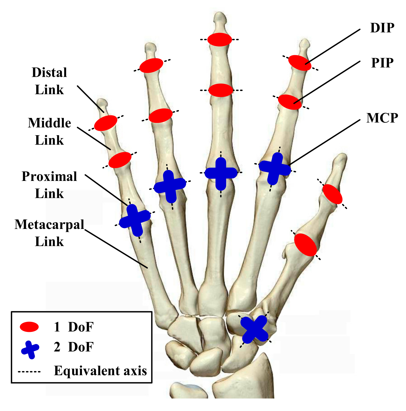
2.1. Anatomy-Based Finger Movement Analysis

There are five fingers in the hand namely the index finger, middle finger, ring finger, little finger and thumb. The thumb includes three independent joints, i.e., the carpo-metacarpal (CMC), metacarpo-phalangeal (MCP), and interpharangeal (IP) joints. The other four fingers include the MCP, proximal phalangeal (PIP) and distal phalangeal (DIP) joints. There exists a larger number of degree of freedom (DoF) within a limited space for the hand, in addition, the internal structure of the synovial joints contains soft tissues, so the joints are not axially aligned in the traditional sense, and the length of the fingers varies greatly in different patients [37]. Although exoskeletons try to solve these problems by adding springs [38], optimizing the linkage structure [39,40,41], adding haptic assist modules [42], and adopting soft robot forms [43,44,45], it is still difficult to apply in clinical practice. When it comes to the structural design of the end-effector type, the complexity of the internal motions and articulations for the hand does not play such an important role, which means it is less sensitive to the hand equivalent model, and thus the model with a fixed axis can be adopted (see Figure 2), which naturally avoids the above problems, so there is still a possibility and necessity for innovation.
As for the characterization of finger movements, a large number of results already exist, which can facilitate our research. It is worth mentioning that a small number of engineering-based modifications have been made to the relevant parameters, which are more in line with the movement habits of human (See Table 1).

2.2. Design Requirements and Preliminary Conception for the Prototype

In practical application scenarios, rehabilitation robots using end-effector perform training by driving coupled movements of the fingers in the F/E motion. They have the advantages of being easy-to-wear and costing little, it’s an important reason that they can be used in medical institutions. Besides, the current finger rehabilitation devices pay less attention to the A/A motion or are simply passively implemented, that is, passive adaptation of A/A motion is achieved by installing passive rotation parts while F/E motion happens.
This results in muscles such as the palmar interossei and the dorsal interossei being unable to be actively trained, which slows the progress of finger rehabilitation and reduces the effectiveness of the training. Therefore, the development of a device with active A/A motion is of clinical importance. In addition, safety is the most important thing that the device needs to be vigilant about during the training process, thus, the following design concepts have been proposed:
  • Rational finger F/E-coupled motion trajectory;
  • Active A/A motion of the four fingers;
  • Compliant control strategy that can ensure safety at all time;
  • Easy-to-wear.
To satisfy these requirements, the F/E and A/A motions are decoupled for consideration. According to the ergonomic and sports anatomy, the index finger plays a crucial role because it is inseparable in almost all finger-related ADL, such as the mouse control in a computer, picking up a cup to drink, sewing clothes with a needle, etc. Thus, for the F/E motion, the analysis has been carried out using the index finger as an example, the other three fingers have a similar motion feature, the Denavit–Hartenberg (D-H) method is used to simulate the range of motion in its natural state (see Figure 3a). The length of the distal link, middle link and proximal link are 24 mm, 25 mm and 46 mm respectively, and the angle for the D-H parameters are shown in Table 1. There exists coupling between DIP and PIP joints, so the fingertip position will not cover all the space in Figure 3a, and the lower edge of the space is closest to the natural F/E motion trajectory, so it is adopted as the design reference.
It is proposed to reproduce the natural motion trajectory through the cam structure. The idea is to establish the equation at the end of the cam by referring to the coupling relationship between the finger joints and presetting partial linkage parameters (see Figure 3b).
Taking the MCP joint as the coordinate origin, a coordinate system is established in the F/E motion plane, and the parametric equation of the trajectory at the fingertip (point C) is established based on the length and coupling relationship of the finger:
x C = 24 cos 3.57 θ 4 + 25 cos 2.57 θ 4 + 46 cos θ 4 z C = 24 sin 3.57 θ 4 + 25 sin 2.57 θ 4 + 46 sin θ 4 ,
A hypothesis is formulated here that the knuckles could reach the maximum bending angle at the same time and thus the proportional relationship between the rotation angles can be quantified according to the dimensional parameters in Table 1, namely, θ3 = 1.57θ4, θ2 = θ4. θ2, θ3 are intermediate transition angles, which are equivalently replaced in the calculation. Considering the length of the finger and the compactness of the overall structure, the size of the finger sleeve, connecting rod and other components are initially set (see Table 2), and the equation for the trajectory parameters at the end of the cam mechanism is established:
x B = x A l A E = 34 cos 3.57 θ 4 + 25 cos 2.57 θ 4 + 46 cos θ 4 15 sin 3.57 θ 4 11 z B = z A l E B = 34 sin 3.57 θ 4 25 sin 2.57 θ 4 46 sin θ 4 15 cos 3.57 θ 4 123
The left part of the curve in Figure 4a is formed by the changes in the DIP joint when the MCP and PIP joints move to the maximum. However, the fingertip needs to be fixed to the finger sleeve, which limits the motion of the PIP joint, in addition, there usually exists a large muscle tension in the fingers, which also limit the range of motion, so the red curve (corresponding angle of the PIP joint is 50–70°) is discarded and the blue part is used as the final design basis (see Figure 4a). Another advantage of this trade-off allows the motor to rotate in one direction during the single pass movement, e.g., the motor can complete the flexion movement without reversing in the latter half of the motion.
In order to facilitate the subsequent kinematic analysis, the parametric equations of the trimmed trajectory are fitted into the form of polynomials, and the results are shown in Figure 4b:
z = 1.556 × 10 6 x 4 0.0001807 x 3 + 0.01311 x 2 0.3356 x 196.3 ,

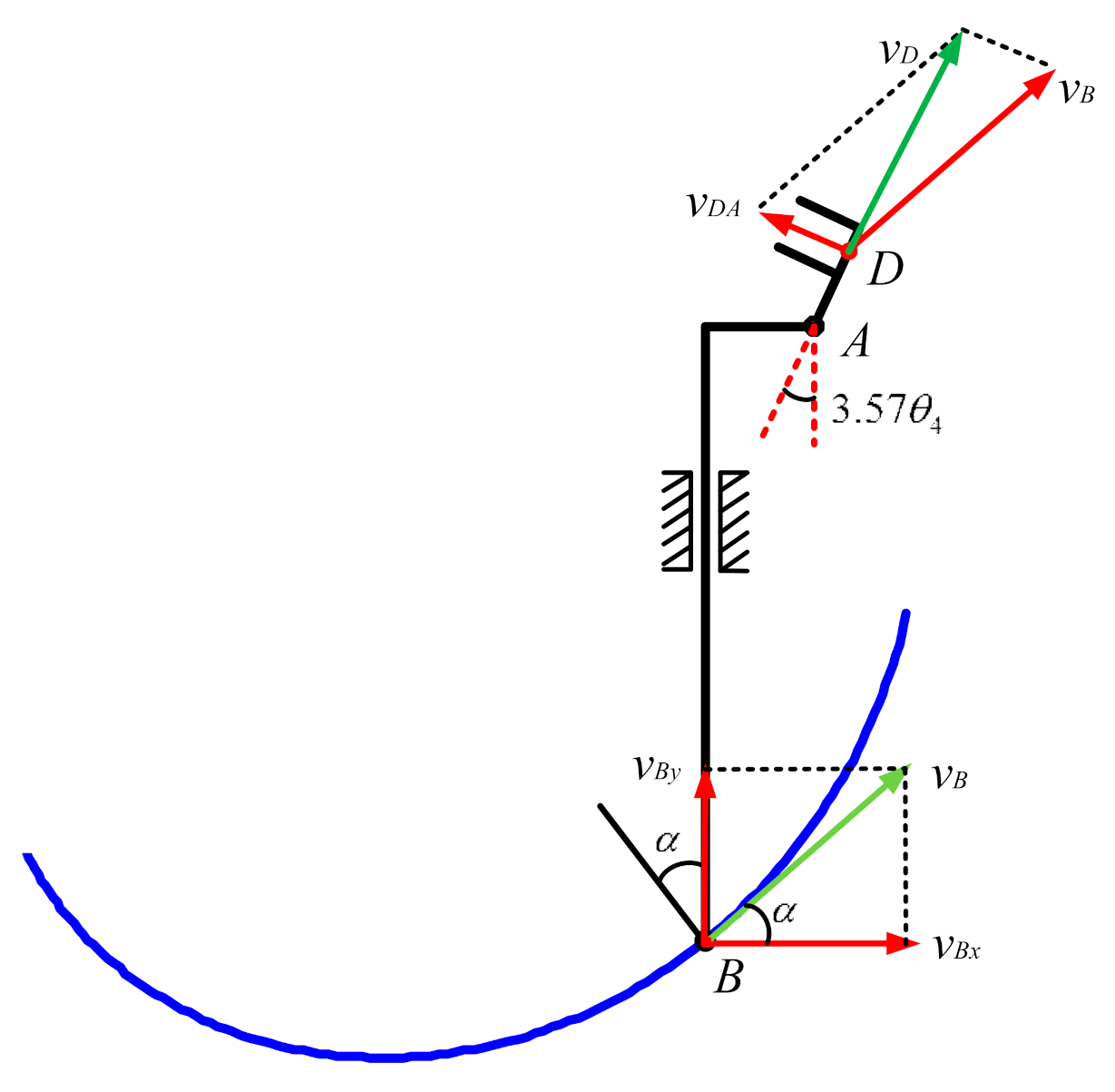
2.3. Kinematic Performance Analysis for the EFRR

During the rehabilitation process, the continuous smoothness of the speed and acceleration of the motion components is an important indicator to ensure that the patient is not subject to force impact, and it is also a reflection of the safety for the device. Therefore, it is necessary to examine these indicators, and in order to facilitate the quantitative analysis, the horizontal velocity (i.e., the moving speed of the slider) at point B is preset to Vbx = 30 mm/s. A sketch of the velocity analysis for the cam mechanism is shown in Figure 5.
In Figure 5, α represents the angle between the instantaneous velocity of point B and the horizontal direction, and the relationship between the points are:
v A = v B x B = v B x t 30 cos α = x B x B 2 + z 2 v D = v A + ω D A l A D
According to the Formulas (2)–(4), it can be concluded that the velocity Vby in the vertical direction at point B and the variation of the joint angle are as follows:
v B y = 0.00018672 x 3 0.016263 x 2 + 0.7866 x 10.068 θ 4 = 0 . 01424 t 3 + 0 . 09116 t 2 0 . 3312 t + 0 . 8307 θ 3 = 0 . 02236 t 3 + 0.1431 t 2 0.52 t + 1.3
To simulate the motion of point D and each joint in ADAMS, some preparations needed to be done first, including deleting nonessential parts (such as bolts, nuts, etc.), defining the initial position and coordinate origin of each part, setting the simulation time and number of motion steps and so on. The results shown in Figure 6 show that the theoretical calculation and simulation of the finger motion basically match within one working cycle, and there is no sudden change in speed and acceleration, and the angle and angular velocity of the three joints of DIP, PIP and MCP also change smoothly without sudden change. This indicates that the motion during the rehabilitation exercise is smooth and the device is safe.

2.4. Illustration of Mechnical Structure for The EFRR

The F/E motion module of the EFRR is shown in Figure 7, including motor, track restraint plate, slide, synchronous belt set, linear bearing, etc. The proMOTION brand DC brush motor is adopted here, the model is 28SYK43, the power 14.8 W, the reduction ratio 64:1, encoder resolution 300 pulses, output TTL level. The curve slot in the track restraint plate is milled based on the fitted curve in the previous section (see Figure 4b). The top of the linear bearing is fitted with a finger sleeve, the bottom is located in the curve slot, and a cylindrical roller is arranged to reduce friction between the linear bearing and the curve slot, this is the advantage of introducing a local degree of freedom. The power from the motor is transferred to the cylindrical roller via the synchronous belt set and the link block, which in turn drives the linear bearing and finger sleeve movement. Pressure sensors have been arranged at the bottom of the sleeve to collect the force in vertical direction from the fingers. The data acquisition cables are placed inside the wire wrap tubes, and it could avoid interference with the sleeve movement during the rehabilitation process. Besides, in order to eliminate the dangling sensation of the patient’s fingers, a one-piece strap has been designed to attach to the sleeve. It increases the comfort for users without additional negative effects.
In the F/E motion module, some necessary details should be described. As for the synchronous belt and the link block (see Figure 8a), the size of the link block is small and it is not easy to make a separated structure. Thus, the synchronous belt is cut, and it is inserted through the holes on each side of the link block, then pressed with the set screws. As for the tensioning structure (see Figure 8b,d), it is necessary when using the belt drive structure, specifically, the mounting bracket for synchronous belt pulley is designed as an independent part, with threaded holes machined on the side for tensioning the belt, and the bottom for fixing itself. Both of the holes are used in conjunction with each other to achieve the tensioning function. As for the limit switches (see Figure 8c), in addition to the design in software programming, a mechanical limit is also necessary to ensure the safety of the device. Here, a micro switch and a touch frame structure are used, and the touch frame has a triangular structure which extends the effective travel of the micro switch and gives the motor enough stopping time, which ensures the safety of system operation and reduces the risk of the micro switch being knocked out.
In addition, EFRR has the function of for A/A motion, the working principle is shown in Figure 9a, and each branched chain represents an F/E motion module. Its lateral movement is achieved by two rotating subs and one moving sub, the mechanical structure is shown in Figure 9b. The motor drives two coaxially arranged synchronous pulleys with different radii. The connecting frame 1 is connected to the upper part of the synchronous belt on the big belt pulley, and the connecting frame 2 is connected to the upper part of the synchronous belt on the small belt pulley. The connecting frame 3 is connected to the lower part of the synchronous belt on the small belt pulley, and the connecting frame 4 is connected to the upper part of the synchronous belt on the big belt pulley. Therefore, one of its working modes is: when the motor rotates counterclockwise, connecting frame 1 and connecting frame 2 move to the left side, connecting frame 3 and connecting frame 4 move to the right side, and the speed of connecting frame 1 and 4 are of the same speed and opposite direction; connecting frame 2 and 3 have the same speed and opposite direction; and the speed ratio of connecting frame 1 and 2 (3 and 4) is the inverse ratio of two pulley diameters, the ratio chosen here is 3:1. The movements of the four connecting frames correspond to the movements of the four fingers, which also conform to the adduction/adduction motion pattern, i.e., the index and little fingers move faster and the middle and ring fingers move slower.

3. Control Strategy of the EFRR

During the rehabilitation training, the driving force changes not only with time, but also with the patient’s muscle tension and the contact force between human and machine. In order to ensure the safety of the patient, an adaptive impedance control strategy based on fuzzy PD was designed, and the control block diagram is shown in Figure 10. Mainly including position control loop, adaptive impedance control loop and safety protection, this strategy can improve the flexibility and adaptability of the device in the unstructured environment to ensure the effective rehabilitation process and avoid secondary injuries to patients.
In the position control loop, the input e(t) is the deviation of the desired position xd from the actual position x. A fuzzy PD controller is applied to the position control loop to calculate the input u(t) of the accused object, TL is the external disturbance term, which mainly includes the disturbance generated by the frictional force of the slider during the power transmission; as for the adaptive impedance control loop, the output of the position control loop is the input of this loop, ef is the difference between the actual contact force fe of the man-machine and the theoretical contact force fd, which is used as the input of the adaptive impedance controller, and the position correction quantity Δx of the controller is the output of this controller, and is also the correction amount of the desired position xd; regarding the safety protection, the input is the actual man-machine contact force fe, and fmax is the safety threshold of the contact force.

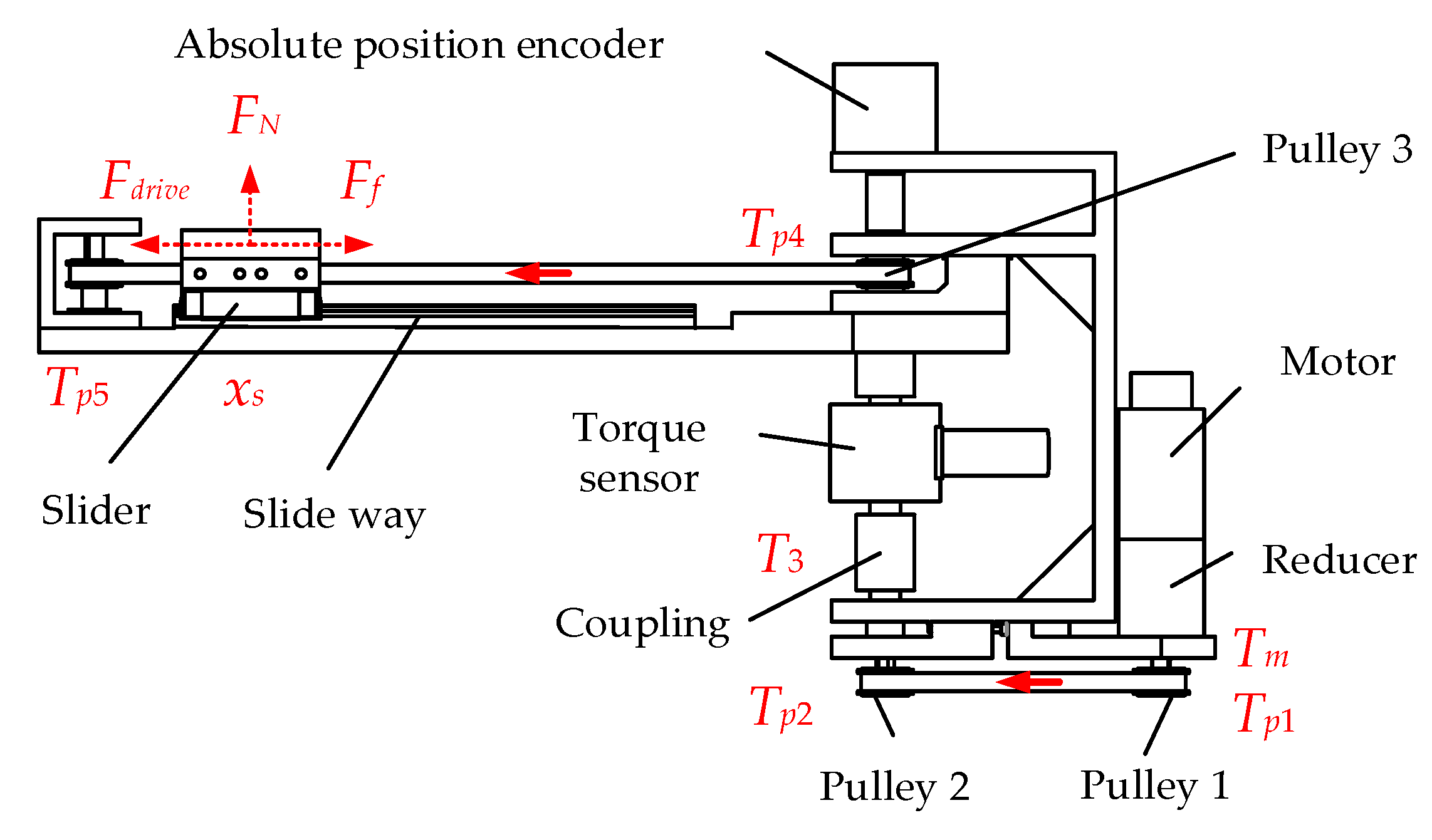
3.1. Dynamic Model Solution of Mechanical Part

As mentioned before, EFRR is modular in design and its four-finger structure is similar, so the analysis of other modules can be obtained by analogy. The dynamics of the F/E motion module from the motor to the slider has been modeled. In order to obtain more information, torque sensors and absolute position encoders were installed on the experimental prototype, as shown in Figure 11.
According to the motion transfer process of the module, the dynamic equations and mathematical relations of the intermediate components can be expressed as:
T m = J s d 2 θ m d t 2 + B s d θ m d t + T p 1 T p 1 = J p 1 d 2 θ m d t 2 + J p 2 d 2 θ m d t 2 + J 3 d 2 θ m d t 2 + J p 4 d 2 θ m d t 2 + J p 5 d 2 θ m d t 2 + F d r i v e d 2 F d r i v e = m t d 2 x s d t 2 + μ v d x s d t + μ c m t g x S = θ m d 2 ,
where, Tm represents the torque of the driving motor, Tp1 is the torque of the pulley 1, Fdrive is the force of the slider and xs indicates the position of the slider. Combining the items in (6), the relationship between motor current and torque T m = K t i a is brought into the result as follows:
T m = 2 d J s + J p 1 + J p 2 + J 3 + J p 4 + J p 5 + m t d 2 4 d 2 x s d t 2 + B s 2 d + μ v d 2 d x s d t + T L ,
where, T L = μ c m t g d 2 is the result of considering the Coulomb friction term in the force analysis of the slider, which has a small effect on the system as a perturbation. In Equation (7), the symbols that are not described are shown in Table 3.

3.2. Fuzzy PD Control Algorithm

The control system of EFRR is carried out on the basis of the fuzzy control PD algorithm, which is used to improve the system response and the tracking performance for the given signal. Fuzzy PD control is a method that combines fuzzy control with a conventional PD algorithm. It adjusts the proportional and differential coefficients by designing fuzzy controller to achieve higher accuracy. The main process includes four steps of fuzzification, rule base establishment, logic judgment and defuzzification. First, by comparing the unit step response curves with different initial parameters, the original adjustment parameters of the controller are determined by using the engineering trial method. They are the k p 0 = 0 . 08 , k d 0 = 0.2 . The input error value of the fuzzy controller is the position error of the slider, the value of the error fuzzy domain is [−3, 3], and the domain of the rate e ˙ is [−1, 1]; the domain of the error for the rate Δkp is [−0.1, 0.1], and the domain of the error for the Δkd is [−0.1, 0.1]. Considering the accuracy of fuzzy expression and response speed, the fuzzy set is chosen as {negative large, negative medium, negative small, zero, positive small, positive medium, positive large}, and the symbolic expression is {NB,NM,NS,ZO,PS,PM,PB}. The triangular affiliation function is chosen to realize the transformation from exact to fuzzy values, and the area center of gravity method is used for defuzzification. The fuzzy control rule table of the Δkp and Δkd are shown in Table 4 and Table 5.

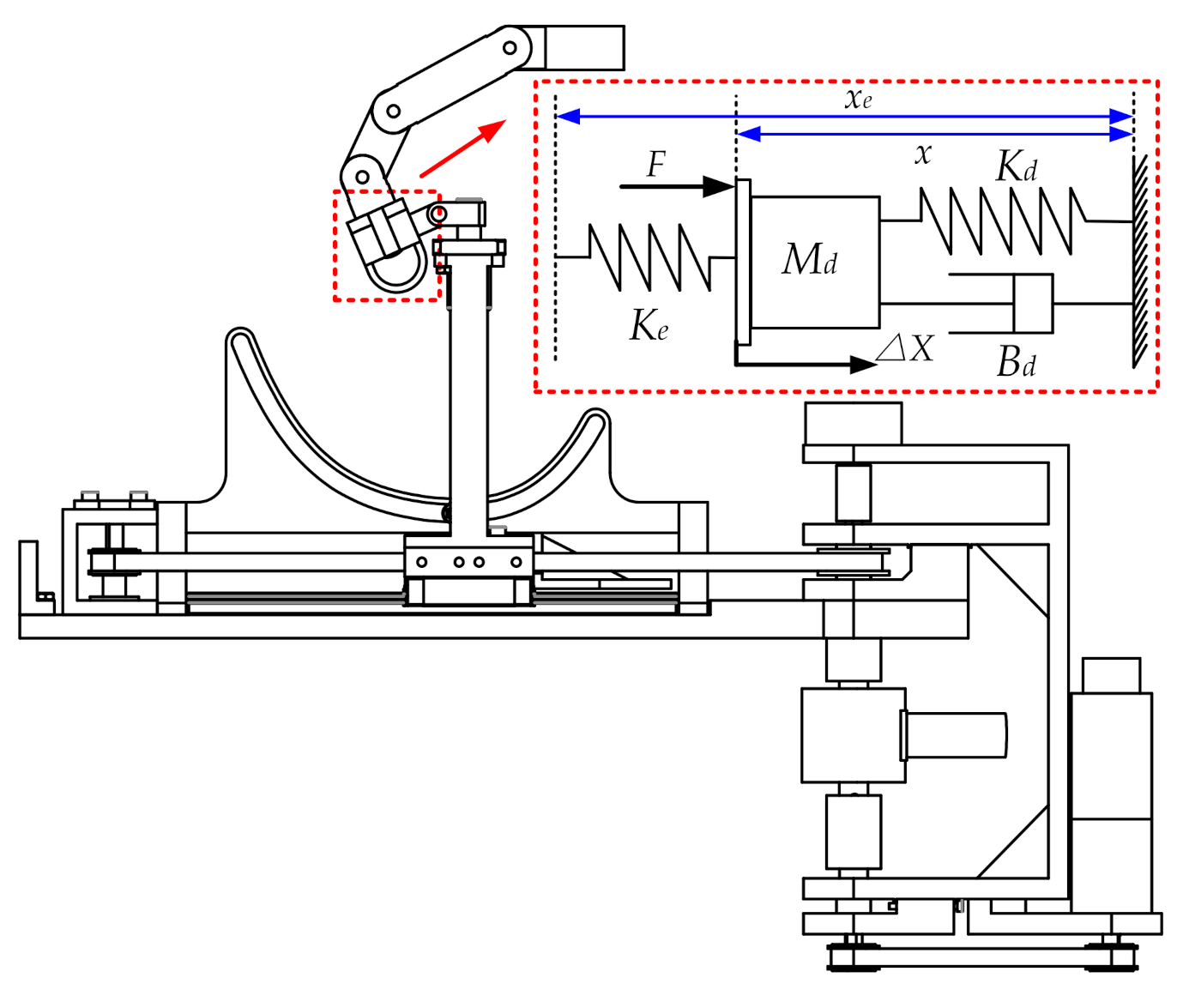
3.3. Adaptive Impedance Control Strategy

In position control mode, the output of the system is aimed at following the given position, and lack of control for the force and torque. Since the patient’s fingertip is connected to the device while training, the torque from the motor will cause damage to the patient when the fingers cannot move according to the preset trajectory due to the excessive muscular tone. Therefore, it is not enough for the robot to have the position tracking feature only, compliant control is also needed to ensure the safety of the patients. Pressure sensors are arranged on the finger sleeve to collect the contact force between man and machine, and position-based adaptive impedance controller has been proposed to guarantee the compliance of the device. This linear adaptive impedance with viscous damping is adequate for the global strategy. The adopted impedance model is:
M d Δ X ¨ + B d Δ X ˙ + K d Δ X = Δ F ,
where, Md, Bd and Kd represents the inertia, damping and stiffness respectively, ΔF represents the deviation of the actual contact force from the target contact force, and ΔX represents the correction amount of the position in the device. There exists one DoF in the flexion/extension motion module and the relationship in Formula (8) could be described by the mass-spring-damping system:
m d x ¨ r x ¨ + b d x ˙ r x ˙ + k d x r x = e f
The equivalent model of the single flexion/extension motion module in contact with the environment is shown in Figure 12.
When the system reaches stability, the condition that the force deviation should satisfy is:
e f = k d f d k e k d x r x e k e + k d
where, the xe is the location of the environment, ke is the actual position of the device, fd is the theoretical force between the device and the environment, xr is the reference position.

3.4. Safety Protection Model

In order to guarantee the safety of the patients during training process and prevent any possible accidents, not only an emergency stop switch is set on the device, but also a protection strategy is added to the control system. Specifically, the threshold of the man-machine interaction force fmax was defined, and when the actual interaction force fe is greater than the threshold fmax, the switch will be connected to x0, the device returns to the initial position, and all the movements stop, which plays the role of the overload protection. The rehabilitation training process can be carried out only under the condition that fe is less than the threshold fmax. In the clinical application, each patient should be evaluated in advance to examine the maximum force he can tolerate, and the criteria for fmax is determined by the maximum force, besides, a setting interface for fmax on the upper computer should be arranged to ensure safer training process.

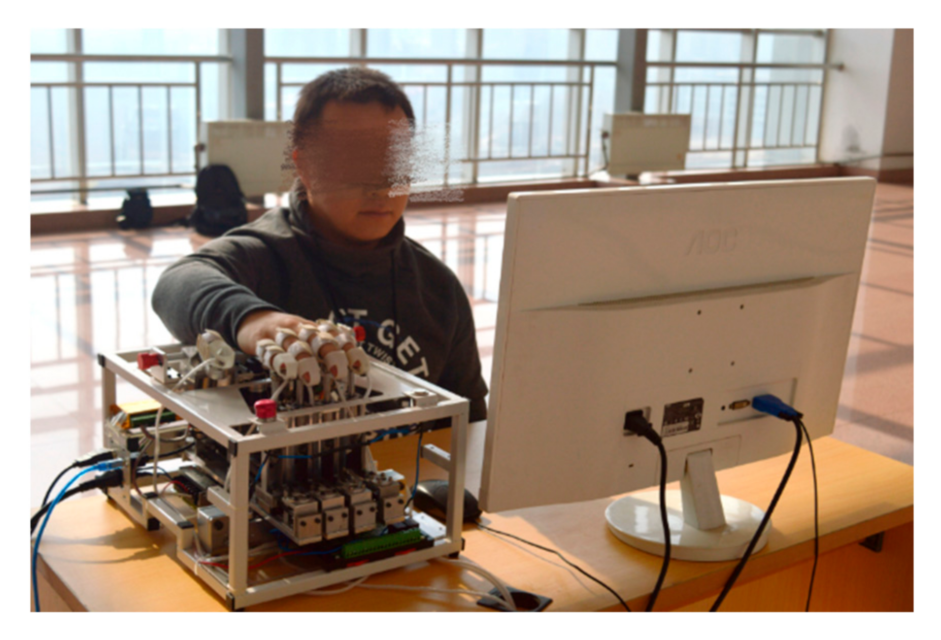
4. Preliminary Experimental Trial of the EFRR

In order to verify the reliability of EFRR’s electromechanical system, and point out the future optimization direction, the necessary preliminary tests has been carried out, including motor driving force tests, position tracking and impedance control experiments. A young male volunteer is recruited to initially verify the performance of the prototype. The experiment scene is shown in Figure 13.
During all the experiments, the fingertips of the volunteer are fixed in the finger sleeve. As for the motor driving force test, the slider moves at the speed of 30 mm/s, and the volunteer applies a constant pressure of 25 N to the sensors at the bottom of the finger sleeve. It is worth mentioning that a 10% deviation is allowed because the force exerted by human hands is not constant. Besides, the force changes could be observed by the host computer to maintain its stability. The driving force is calculated based on the detection result of the torque sensors, and the results are shown in Figure 14.
In Figure 14, the red dotted line is the theoretical calculation curve, the pink area is the allowable range of the driving force caused by the 10% deviation of the contact force, and the blue curve is the experimental data. It could be observed the experimental theoretical calculation curve basically coincide, but, at 0–0.5 s, the experimental data is slightly larger than the theoretical, and even runs out of the allowable range. The possible reason is that the volunteer needs reaction time at the beginning, which causes the finger movement to lag behind the robot. The actual human–machine contact force is greater than 27.5 N (beyond the preset range). Thus, the motor load becomes larger, and so does the force detected by the torque sensor. In 0.5–3.75 s, the volunteer can subjectively adjust the contact force to stabilize it at 25 N by observing the display, so the two curves basically coincide. At 4.13 s, the slider reaches the limit, considering the total length of the slider. The speed is slowly reduced, that is, to less than 30 mm/s, so the measured value is less than the theoretical results at 3.75–4.13 s.
The position control experiment aims to test the tracking performance of EFRR. It consists of the test of fixed position keeping ability and trajectory tracking ability. In the former test (see Figure 15a), the starting position of the slider is zero, and the given position becomes 20 mm at 1s. The purpose is to observe the tracking ability of the device when the given position changes. In the latter test (see Figure 15b), the slider moves sinusoidal from the initial position of 50 mm on both sides, and the observation time is 4 s. It can be observed that no matter the position has a large sudden change or in the case of continuous movement, the lag time of the slider does not exceed 0.1 s, the maximum error does not exceed 4 mm, and no overshoot occurs. There are some reasons that may affect the results of this test. The most likely one is that the tension of the timing belt is not enough, which leads to the backhaul error of the slider, besides, the change of human-machine contact force will also affect the output torque of the motor, which in turn affects the position accuracy.
In the impedance control experiment (see Figure 16), a comparison between traditional impedance and adaptive impedance control was carried out. In traditional impedance control, the contact force would follow the expected value in 0.3 s, and then fluctuate around the expected value of 5 N. The maximum contact force is 7.03 N and the minimum contact force is 2.6 N. In the adaptive impedance control strategy, the contact force follows the expected value in 0.4 s, which is slightly longer than the former. The maximum contact force is 5.95 N and the minimum contact force is 3.6 N. Generally speaking, although the system response is slightly slower than the traditional impedance control, the force following accuracy is higher.

5. Conclusions and Future Work

This paper proposes a finger rehabilitation device named EFRR for stroke patients in clinic or at home. This device adopts the motor-driven approach for the finger rehabilitation and the electronic hardware are placed inside to reduce the overall of the device. This setup can let EFRR adapt to different occasions easier, and is conducive to a wide range of applications. The design of the EFRR has a modularized structure, and it is composed of the components such as synchronous pulleys and belts, which can be easily individually designed. EFRR utilizes cam mechanism to achieve flexion/extension rehabilitation movements and reaches the optimal motion form for the motor during rehabilitation by intercepting the most efficient finger movement law curve, i.e., the motor does not have to reverse during the unidirectional movement of flexion/extension. Moreover, the EFRR achieves the active adduction/abduction rehabilitation movement through one single motor, making up for the neglect of this motion in existing devices with a simple and cost-controllable structure. In addition, some necessary details have been added to the device, such as tensioning structures and limit switches, to ensure the reliability of the equipment. For the control system, a fuzzy PD adaptive impedance control strategy based on position information was designed to control the device for achieving safety, smooth and comfortable. Finally, preliminary experimental trials have verified the effectiveness of the proposed prototype, including motor driving force tests, position tracking and impedance control experiments, and they provide a proof of practicability and industrialization prospect for the proposed prototype. The EFRR is a small rehabilitation device, consisting of a PC and a 430 × 315 × 270 mm actuator, which is compact in the overall size. It is powered by 220 V AC voltage, which is not different from household appliances. In addition, the operation for this device is not complicated and can be operated after simple training. In the future, it could be adapted to the needs of home rehabilitation through further optimization. This becomes even more important especially in the COVID-19 pandemic.
In the future, further improvements are to be made on the EFRR based on patient feedback, including the mechanical design and the control system. For example, lighter materials such as resin or nylon might be used in the noncritical load-bearing parts to reduce the cost and for better transportation. Although the evaluation for this volunteer is positive now, it is also noted that the prototype needs to be tested on real patients instead of volunteers. Quantitative and qualitative assessments (e.g., based on questionnaires, physiological information, etc.) about the equipment are more relevant, and they may expose more problems for the mechanical design and control strategy, that is, clinical tests should be made in the future.

Author Contributions

Methodology, Y.T., H.W. and B.N.; software, Y.Z. and J.D.; validation, J.N.; formal analysis, B.N.; investigation, J.N. and J.D.; data curation, B.N.; writing—original draft preparation, Y.T. and B.N.; writing—review and editing, Y.T. and J.N.; supervision, L.S.; project administration, H.W. All authors have read and agreed to the published version of the manuscript.

Funding

This research was funded by National Natural Science Foundation of China, grant number U1913216; Shanghai Science and Technology Innovation Action Plan, grant number 19441908200; Key research and development program of Hebei, grant number 19211820D and 20371801D.

Institutional Review Board Statement

Not applicable.

Informed Consent Statement

Written informed consent has been obtained from the patient(s) to publish this paper.

Data Availability Statement

Not applicable.

Conflicts of Interest

The authors declare no conflict of interest.

References

  1. Feigin, V.L.; Mensah, G.A.; Norrving, B.; Murray, C.J.; Roth, G.A. Atlas of the Global Burden of Stroke (1990–2013): The GBD 2013 Study. Neuroepidemiology 2015, 45, 230–236. [Google Scholar] [CrossRef]
  2. Feigin, V.L.; Nguyen, G.; Cercy, K.; Johnson, C.O.; Alam, T.; Parmar, P.G.; Abajobir, A.A.; Abate, K.H.; Abd-Allah, F.; Abejie, A.N.; et al. Global, Regional, and Country-Specific Lifetime Risks of Stroke, 1990 and 2016. N. Engl. J. Med. 2018, 379, 2429–2437. [Google Scholar] [CrossRef] [PubMed]
  3. World Health Statistics 2020: Monitoring Health for the SDGs, Sustainable Development Goals. Available online: https://www.who.int/data/gho/publications/world-health-statistics (accessed on 26 April 2021).
  4. Hou, Z.; Zhao, X.; Cheng, L.; Wang, Q.; Wang, W. Recent Advances in Rehabilitation Robots and Intelligent Assistance Systems. ACTA Autom. Sin. 2016, 42, 1765–1779. [Google Scholar] [CrossRef]
  5. Krebs, H.I. Rehabilitation robotics: An academic engineer perspective. In Proceedings of the 2011 Annual International Conference of the IEEE Engineering in Medicine and Biology Society, Boston, MA, USA, 30 August–3 September 2011; pp. 6709–6712. [Google Scholar]
  6. Suarez-Escobar, M.; Rendon-Velez, E. An overview of robotic/mechanical devices for post-stroke thumb rehabilitation. Disabil. Rehabil. Assist. Technol. 2018, 13, 683–703. [Google Scholar] [CrossRef] [PubMed]
  7. Aggogeri, F.; Mikolajczyk, T.; O’Kane, J. Robotics for rehabilitation of hand movement in stroke survivors. Adv. Mech. Eng. 2019, 11. [Google Scholar] [CrossRef]
  8. Hwang, C.H.; Seong, J.W.; Son, D.S. Individual finger synchronized robot-assisted hand rehabilitation in subacute to chronic stroke: A prospective randomized clinical trial of efficacy. Clin. Rehabil. 2012, 26, 696–704. [Google Scholar] [CrossRef] [PubMed]
  9. Pinter, D.; Pegritz, S.; Pargfrieder, C.; Reiter, G.; Wurm, W.; Gattringer, T.; Linderl-Madrutter, R.; Neuper, C.; Fazekas, F.; Grieshofer, P.; et al. Exploratory study on the effects of a robotic hand rehabilitation device on changes in grip strength and brain activity after stroke. Top. Stroke Rehabil. 2013, 20, 308–316. [Google Scholar] [CrossRef] [PubMed]
  10. Dovat, L.; Lambercy, O.; Gassert, R.; Maeder, T.; Milner, T.; Leong, T.C.; Burdet, E. HandCARE: A cable-actuated rehabilitation system to train hand function after stroke. IEEE Trans. Neural Syst. Rehabil. Eng. 2008, 16, 582–591. [Google Scholar] [CrossRef] [PubMed]
  11. Bouzit, M.; Burdea, G.; Popescu, G.; Boian, R. The Rutgers Master II-new design force-feedback glove. IEEE/ASME Trans. Mechatron. 2002, 7, 256–263. [Google Scholar] [CrossRef] [Green Version]
  12. Hesse, S.; Kuhlmann, H.; Wilk, J.; Tomelleri, C.; Kirker, S.G. A new electromechanical trainer for sensorimotor rehabilitation of paralysed fingers: A case series in chronic and acute stroke patients. J. Neuroeng. Rehabil. 2008, 5, 21. [Google Scholar] [CrossRef] [PubMed] [Green Version]
  13. Ben-Tzvi, P.; Ma, Z. Sensing and Force-Feedback Exoskeleton (SAFE) Robotic Glove. IEEE Trans. Neural Syst. Rehabil. Eng. 2015, 23, 992–1002. [Google Scholar] [CrossRef]
  14. Zhang, N.; Niu, B.; Wang, H.; Chen, F.; Yan, H.; Jin, Z. Design of active disturbance rejection controller finger rehabilitation robot structure and control system. Sci. Tech. Engrg. 2019, 19, 166–173. [Google Scholar] [CrossRef]
  15. Zheng, Y.; Chen, L.; Wang, G.; Liu, X.; Dong, X.; Wang, J. A Structure Optimal Design of Training Devices for the Under-Actuated Hand Rehabilitation. J. Xian Jiaotong Univ. 2015, 49, 151–156. [Google Scholar] [CrossRef]
  16. Ito, S.; Kawasaki, H.; Ishigure, Y.; Natsume, M.; Mouri, T.; Nishimoto, Y. A design of fine motion assist equipment for disabled hand in robotic rehabilitation system. J. Frankl. Inst. 2011, 348, 79–89. [Google Scholar] [CrossRef]
  17. Agarwal, P.; Deshpande, A.D. Series Elastic Actuators for Small-Scale Robotic Applications. J. Mech. Robot. 2017, 9. [Google Scholar] [CrossRef]
  18. Agarwal, P.; Fox, J.; Yun, Y.; O’Malley, M.K.; Deshpande, A.D. An index finger exoskeleton with series elastic actuation for rehabilitation: Design, control and performance characterization. Int. J. Robot. Res. 2015, 34, 1747–1772. [Google Scholar] [CrossRef]
  19. Sandoval-Gonzalez, O.; Jacinto-Villegas, J.; Herrera-Aguilar, I.; Portillo-Rodiguez, O.; Tripicchio, P.; Hernandez-Ramos, M.; Flores-Cuautle, A.; Avizzano, C. Design and Development of a Hand Exoskeleton Robot for Active and Passive Rehabilitation. Int. J. Adv. Robot. Syst. 2017, 13. [Google Scholar] [CrossRef] [Green Version]
  20. Cempini, M.; Cortese, M.; Vitiello, N. A Powered Finger–Thumb Wearable Hand Exoskeleton With Self-Aligning Joint Axes. IEEE/ASME Trans. Mechatron. 2015, 20, 705–716. [Google Scholar] [CrossRef]
  21. Choi, W.-H.; Takeda, Y. Geometric Design and Prototyping of a (2-RRU)-URR Parallel Mechanism for Thumb Rehabilitation Therapy. Machines 2021, 9, 50. [Google Scholar] [CrossRef]
  22. Cappello, L.; Meyer, J.T.; Galloway, K.C.; Peisner, J.D.; Granberry, R.; Wagner, D.A.; Engelhardt, S.; Paganoni, S.; Walsh, C.J. Assisting hand function after spinal cord injury with a fabric-based soft robotic glove. J. Neuroeng. Rehabil. 2018, 15, 59. [Google Scholar] [CrossRef]
  23. Yap, H.K.; Jeong Hoon, L.; Nasrallah, F.; Goh, J.C.H.; Yeow, R.C.H. A soft exoskeleton for hand assistive and rehabilitation application using pneumatic actuators with variable stiffness. In Proceedings of the 2015 IEEE International Conference on Robotics and Automation (ICRA), Seattle, DC, USA, 26–30 May 2015; pp. 4967–4972. [Google Scholar]
  24. Jeong, U.; In, H.-K.; Cho, K.-J. Implementation of various control algorithms for hand rehabilitation exercise using wearable robotic hand. Intell. Serv. Robot. 2013, 6, 181–189. [Google Scholar] [CrossRef]
  25. Butzer, T.; Lambercy, O.; Arata, J.; Gassert, R. Fully Wearable Actuated Soft Exoskeleton for Grasping Assistance in Everyday Activities. Soft Robot. 2021, 8, 128–143. [Google Scholar] [CrossRef] [PubMed]
  26. Nycz, C.J.; Butzer, T.; Lambercy, O.; Arata, J.; Fischer, G.S.; Gassert, R. Design and Characterization of a Lightweight and Fully Portable Remote Actuation System for Use With a Hand Exoskeleton. IEEE Robot. Autom. Lett. 2016, 1, 976–983. [Google Scholar] [CrossRef]
  27. Arata, J.; Ohmoto, K.; Gassert, R.; Lambercy, O.; Fujimoto, H.; Wada, I. A new hand exoskeleton device for rehabilitation using a three-layered sliding spring mechanism. In Proceedings of the 2013 IEEE International Conference on Robotics and Automation, Karlsruhe, Germany, 6–10 May 2013; pp. 3902–3907. [Google Scholar]
  28. Felix Orlando, M.; Behera, L.; Dutta, A.; Saxena, A. Optimal Design and Redundancy Resolution of a Novel Robotic Two-Fingered Exoskeleton. IEEE Trans. Med. Robot. Bionics 2020, 2, 59–75. [Google Scholar] [CrossRef]
  29. Cheng, L.; Chen, M.; Li, Z. Design and Control of a Wearable Hand Rehabilitation Robot. IEEE Access 2018, 6, 74039–74050. [Google Scholar] [CrossRef]
  30. Park, Y.; Jo, I.; Bae, J. Development of a dual-cable hand exoskeleton system for virtual reality. In Proceedings of the 2016 IEEE/RSJ International Conference on Intelligent Robots and Systems (IROS), Daejeon, Korea, 9–14 October 2016; pp. 1019–1024. [Google Scholar]
  31. Chiri, A.; Vitiello, N.; Giovacchini, F.; Roccella, S.; Vecchi, F.; Carrozza, M.C. Mechatronic Design and Characterization of the Index Finger Module of a Hand Exoskeleton for Post-Stroke Rehabilitation. IEEE/ASME Trans. Mechatron. 2012, 17, 884–894. [Google Scholar] [CrossRef]
  32. Wu, J.; Huang, J.; Wang, Y.; Xing, K. A Wearable Rehabilitation Robotic Hand Driven by PM-TS Actuators. In Proceedings of the Intelligent Robotics and Applications, Berlin/Heidelberg, Germany, 10–12 November 2010; pp. 440–450. [Google Scholar]
  33. Jones, C.L.; Wang, F.; Morrison, R.; Sarkar, N.; Kamper, D.G. Design and Development of the Cable Actuated Finger Exoskeleton for Hand Rehabilitation Following Stroke. IEEE ASME Trans. Mechatron. 2014, 19, 131–140. [Google Scholar] [CrossRef]
  34. Polygerinos, P.; Wang, Z.; Galloway, K.C.; Wood, R.J.; Walsh, C.J. Soft robotic glove for combined assistance and at-home rehabilitation. Robot. Auton. Syst. 2015, 73, 135–143. [Google Scholar] [CrossRef] [Green Version]
  35. Bertelli, J.; Tavares, K. Little finger abduction and adduction testing in ulnar nerve lesions. Hand Surg. Rehabil. 2018, 37, 368–371. [Google Scholar] [CrossRef] [PubMed]
  36. Calais-Germain, B. Anatomy of Movement; Eastland Press: Seattle, DC, USA, 2015. [Google Scholar]
  37. Jianfeng, L.; Zhaojing, Z.; Leiyu, Z.; Chunjing, T.; Run, J.; Jinhong, F. Review of the Kinematic Compatibility Design of Hand Exoskelentons. J. Shanghai Jiao Tong Univ. 2018, 52, 729–742. [Google Scholar] [CrossRef]
  38. Lu, X.; Yang, Z.; Chen, Y.; Wang, J. Structure Design of a Wearable Device for Hand Rehabilitation. In Proceedings of the 2016 9th International Symposium on Computational Intelligence and Design (ISCID), Hangzhou, China, 10–11 December 2016; pp. 93–96. [Google Scholar]
  39. Hsu, T.-H.; Chiang, Y.-C.; Chan, W.-T.; Chen, S.-J. A Finger Exoskeleton Robot for Finger Movement Rehabilitation. Inventions 2017, 2, 12. [Google Scholar]
  40. Hernández-Santos, C.; Davizón, Y.A.; Said, A.R.; Soto, R.; Félix-Herrán, L.C.; Vargas-Martínez, A. Development of a Wearable Finger Exoskeleton for Rehabilitation. Appl. Sci. 2021, 11, 4145. [Google Scholar] [CrossRef]
  41. Secciani, N.; Bianchi, M.; Ridolfi, A.; Vannetti, F.; Volpe, Y.; Governi, L.; Bianchini, M.; Allotta, B. Tailor-Made Hand Exoskeletons at the University of Florence: From Kinematics to Mechatronic Design. Machines 2019, 7, 22. [Google Scholar] [CrossRef] [Green Version]
  42. Choukou, M.-A.; Mbabaali, S.; Bani Hani, J.; Cooke, C. Haptic-Enabled Hand Rehabilitation in Stroke Patients: A Scoping Review. Appl. Sci. 2021, 11, 3712. [Google Scholar] [CrossRef]
  43. Shahid, T.; Gouwanda, D.; Nurzaman, S.G.; Gopalai, A.A. Moving toward Soft Robotics: A Decade Review of the Design of Hand Exoskeletons. Biomimetics 2018, 3, 17. [Google Scholar] [CrossRef] [Green Version]
  44. Tarvainen, T.V.J.; Fernandez-Vargas, J.; Yu, W. New Layouts of Fiber Reinforcements to Enable Full Finger Motion Assist with Pneumatic Multi-Chamber Elastomer Actuators. Actuators 2018, 7, 31. [Google Scholar] [CrossRef] [Green Version]
  45. Tarvainen, T.V.J.; Yu, W. Pneumatic Multi-Pocket Elastomer Actuators for Metacarpophalangeal Joint Flexion and Abduction-Adduction. Actuators 2017, 6, 27. [Google Scholar] [CrossRef] [Green Version]
Figure 1. Prototype of the EFRR. EFRR: end-effector finger rehabilitation robot.
Machines 09 00110 g001
Figure 2. Equivalent model of the human hand.
Machines 09 00110 g002
Figure 3. (a) The range of motion for the index finger in its natural state; (b) a sketch of the cam structure that reproduces the natural motion of the finger.
Machines 09 00110 g003
Figure 4. (a) Trajectory constraint curves and its trade-offs of the cam structure; (b) fitted curve of the trajectory.
Machines 09 00110 g004
Figure 5. The velocity analysis for the cam mechanism.
Machines 09 00110 g005
Figure 6. Analysis of the key point in the scheme. (a) Speed change of the finger sleeve; (b) acceleration speed change of the finger sleeve; (c) angle change of the three finger joints; (d) angular velocity change of the joints.
Machines 09 00110 g006
Figure 7. The flexion/extension motion module of the EFRR.
Machines 09 00110 g007
Figure 8. Necessary details of the module. (a) The synchronous belt and the link block; (b) the tensioning structure; (c) the limit switches; (d) drawings of the tensioning structure.
Machines 09 00110 g008
Figure 9. Introduction of the adduction/adduction module. (a) The working principle; (b) the drive structure.
Machines 09 00110 g009
Figure 10. Control strategy of the EFRR: adaptive impedance control strategy based on fuzzy PD.
Machines 09 00110 g010
Figure 11. The dynamics of the flexion/extension motion module from the motor to the slider.
Machines 09 00110 g011
Figure 12. The equivalent model of the single module in contact with the environment.
Machines 09 00110 g012
Figure 13. (a) Prototype of the EFRR; (b) scenes of volunteers wearing EFRR for experiments.
Machines 09 00110 g013
Figure 14. Comparison of the simulation and real situation for driving force.
Machines 09 00110 g014
Figure 15. (a) Fixed location tracking results; (b) sinusoidal trajectory tracking results.
Machines 09 00110 g015
Figure 16. The left shows the results of conventional impedance control experiments; the right shows the results of adaptive impedance control experiments.
Machines 09 00110 g016
Table 1. Parameters of finger motion characteristics.
JointsDoFMovementRange (°)Torque (N·m)
FingersMCP2A/A0~450.16
F/E0~700.29
PIP1F/E0~1100.29
DIP1F/E0~70\
ThumbCM2A/A0~600.3
F/E0~900.3
MP1F/E0~600.26
IP1F/E0~700.26
Table 2. Parameters of the preset components.
SymbolsImplicationValue (mm)
lCDLength of the finger sleeve10
lADLength of the finger sleeve nod15
lAELength of horizontal linkage11
lEBLength of vertical connecting rod123
Table 3. Parameters in Equation (5).
NumberSymbolsImplicationUnit
1KtTorque constant of the motor\
2iaCurrent of the motorA
3TpiTorque of the pulley iN·m
4T3Torque of the sensorN·m
5JsRotational inertia of the motor and reducerkg·m2
6JpiRotational inertia of the pulley ikg·m2
7J3Rotational inertia of the torque sensorkg·m2
8mtMass of the slider and the object on itkg
9dRadius of the pulleysm
10BsMotor damping factor (converted to reducer)\
11µvCoefficient of viscous friction of slide way\
12µcCoulomb friction coefficient of slide way\
Table 4. Fuzzy rule of the Δkp.
e/deNBNMNSZOPSPMPB
NBPBPBPMPMPSZOZO
NMPBPBPMPSPSZONS
NSPMPMPMPSZONSNS
ZOPMPSPSZONSNMNM
PSPSZOZONSNSNMNM
PMPSNSNSNMNMNMNB
PBZONMNMNMNMNBNB
Table 5. Fuzzy rule of the Δkd.
e/deNBNMNSZOPSPMPB
NBPSNSNBNBNBNMPS
NMPSNSNBNMNMNSZO
NSZONSNMNMNSNSZO
ZOZONSNSNSNSNSZO
PSZOZOZOZOPBZOZO
PMPBPSPSPSPSPBPB
PBPBPMPMPSPSPBPB
Publisher’s Note: MDPI stays neutral with regard to jurisdictional claims in published maps and institutional affiliations.

