1. Introduction
The bearing-rotor system is widely used in many rotating machineries, such as industrial compressors, steam turbines and aero engines. These shafts are usually composed of several sections which may not reach the proper design state due to structural characteristics or insufficient machining during the installation process [
1,
2]. As a result, the initial bending is inevitably generated and dynamic vibration of the rotor system is increased together with mass eccentricity. It has been proven to have an important influence on the dynamic response of rotor systems, and more alternating stresses acting on the shaft may increase the probability of unpredicted crack or rubbing faults [
3,
4]. Crack monitoring using vibrations is always the hot topic in fault diagnosis of mechanical equipment. De Lacalle proposed an assessment method of reliability and failure probability by comparing numerical simulation and experimental results [
5]. Copo developed an inspection scheduling method of gas turbine based on a probabilistic crack propagation. When the model was established, many uncertainties in material properties, defect inspection capabilities, weld geometry and loads have also been taken into consideration [
6].
Recently, great attentions have focused on the time-varying stiffness of a cracked rotor in vibration analysis and fault diagnosis [
7,
8]. Three different models of fatigue crack are widely adopted in the stability analysis of rotor system at present, namely, the open model, the switching model and the breathing model. The switching crack model believes that the transition of crack state is completed immediately and has many applications in rotor crack fault and dynamic parameter identification [
9,
10]. For the large rotors running at low speed, crack state changes gradually during rotation. As the crack section is subjected to the alternating tensile and compressive stresses, there is a continuous variation between the open and closed state of the crack. Just like the human breathing process, the contact area of the crack segment decreases gradually when the closed crack begins to open, and the contact area increases when the open crack begins to close. Mayes used a continuous first-order cosine model to describe the change of crack state, and formed a simple breathing model which was considered to be closer to the actual situation and accepted by researchers [
11]. An improved breathing mechanism proposed by Al-Shudeifat has been widely applied to crack detection and nonlinear behavior analysis of cracked rotor systems in recent years [
12]. Many assumptions and approximations in traditional breathing functions are removed and the harmonic balance method is employed to solve vibration [
13]. The semi discretization method is also extensively used to solve the differential equations, and Urbikain believes that this method is more effective to obtain a dynamic response [
14,
15]. This mechanism is developed for the large and heavy shaft of rotating machines of a breathing crack. In these cases, the horizontal line passing through the centroid of a closed section is taken as the neutral axis if the shaft diameter is large enough.
As for the non-gravity dominant rotors with transverse cracks, several modified breathing models were explored to avoid the influence of mass [
16]. The breathing mechanism may be dominated by unbalanced force or other forces, and calculating the area moment of inertia of the uncracked segment becomes more complicated. Especially, detecting the change of dynamic response becomes very difficult if the direction of unbalance happens to be the same as the direction of the crack [
17,
18]. Subsequently, many breathing functions dominated by different dynamic loadings are continuously developed due to different types of cracked rotors or operating conditions [
19,
20]. In order to obtain a more accurate time-varying stiffness, the stress intensity factors and strain energy density are employed to determine crack state and neutral axis [
21,
22]. Rubio proposed a method based on the stress intensity factor of an open crack with sickle shape to determine the relative depth and front position of the crack [
23]. However, these methods are established in an ideal state and the initial bending is taken as one part of mass imbalance or neglected for simplification [
24].
The current studies on initial bending deformation of a rotor system are mostly aimed at its effect on the dynamic response. Identification of bending faults are based on the difference in the dynamic response of bearing and shaft [
25,
26]. Yang found if the initial bending and geometrical nonlinearity coexist in a rotor system, the vibrations are obviously increased by the initial bending’s degree and the jump phenomenon appears [
27]. Dynamical results confirmed that obvious changes in both vibration equation and breathing functions of the crack are taking place due to initial bending. The tension stress field and compression stress field change with the bending response of rotating shaft, and the overall closed area is also different from that calculated by the traditional models [
28,
29]. Deviations are inevitably generated when calculating the moments of inertia of the closed area and the time-varying stiffness using these functions. Thus, an important problem to be solved firstly for crack fault diagnosis is to obtain the accurate time-stiffness functions of the rotor system with initial bending. That is one important reason that the stability of cracked rotor obtained in previous studies is different from the actual situation and it is far from enough to assess engineering machinery conditions using previous models [
30].
Hence, accurate breathing functions and dynamical responses of cracked rotors with initial bending are presented here. Firstly, the influence of initial bending on dynamic response of a rotating shaft is analyzed based on the finite element equations. The difference from previous studies is that the initial bending and mass imbalance are separated in dynamic modeling and state transition of the crack. Then, the neutral axis position and area moment of inertia of overall closed portion are calculated accurately by integral technology. After the time-varying stiffness matrix is obtained, vibration equation of the system is established and the stability is investigated. Finally, numerical simulation is employed to compare the results with traditional ones. It is found that the initial bending is an important factor influencing the breathing mechanism and stability regions of the crack rotor.
2. Stability and Improved Breathing Function
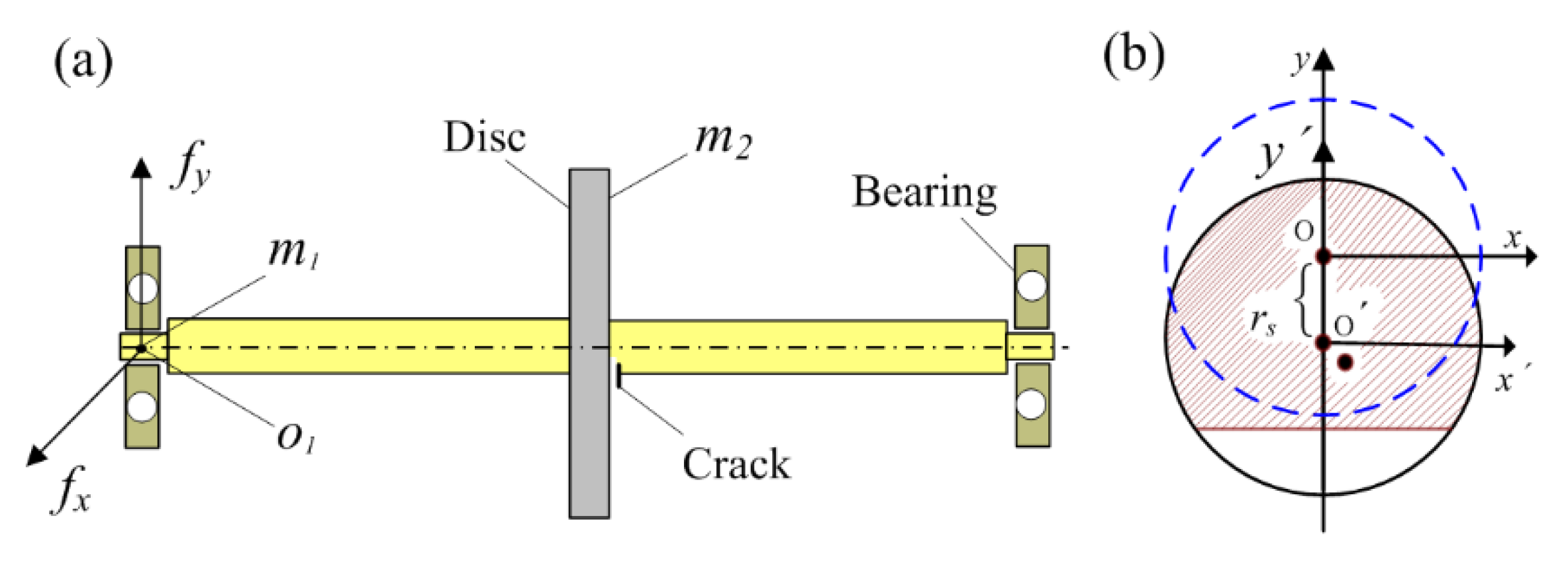
A simplified rotor model composed of a shaft and a disc installed at the middle point of the shaft is shown in
Figure 1. The shaft with static deformation is supported by two journal bearings. The transverse crack is supposed to be in the same position as the disc. Assuming initial displacement of the centroid
is
as shown in
Figure 1, another point besides
is the center of mass with the eccentric distance
ε (
).
Neglecting torsional vibration, only lateral vibration is considered and the vibration equation of the cracked rotor with initial bending can be established as [
29].
where,
is the displacement of bearing,
is the displacement of disc,
is the initial deflection of the shaft,
are mass matrixes,
are damping matrixes,
are gyroscopic matrix,
are time-varying stiffness which should be formulated. Assuming the angle between initial bending and normal direction of the crack is zero here.
is unbalance direction vector,
F is oil force calculated by the formula for short journal bearing.
and
are vectors.
The parameters involved in the rotor–bearing system are shown in
Table 1, which also can be found in Refs. [
3,
28]. By defining an initial bending coefficient as
, let
, the Equation (1) can be transformed in united form as
where,
B is generalized coefficient matrix,
A is parameter matrix of initial bending,
,
.
The displacement of point is calculated as , where is the dynamic response due to unbalanced forces.
According to the traditional rotor dynamics, the homogeneous equation of Equation (2) is transformed as
where,
,
. As
, Equation (1) can be solved as
,
is rotating speed.
is response phase of unbalance force.
is the angle between initial bending and displacement vector calculated as
If eccentricity of the disc is not considered, Equation (5) can be written as
[
31]. It can be seen that the displacement of rotating shaft is the unbalance response base on the initial bending. Initial bending amplitude does not affect the calculation of
which can be seen from Equation (6).
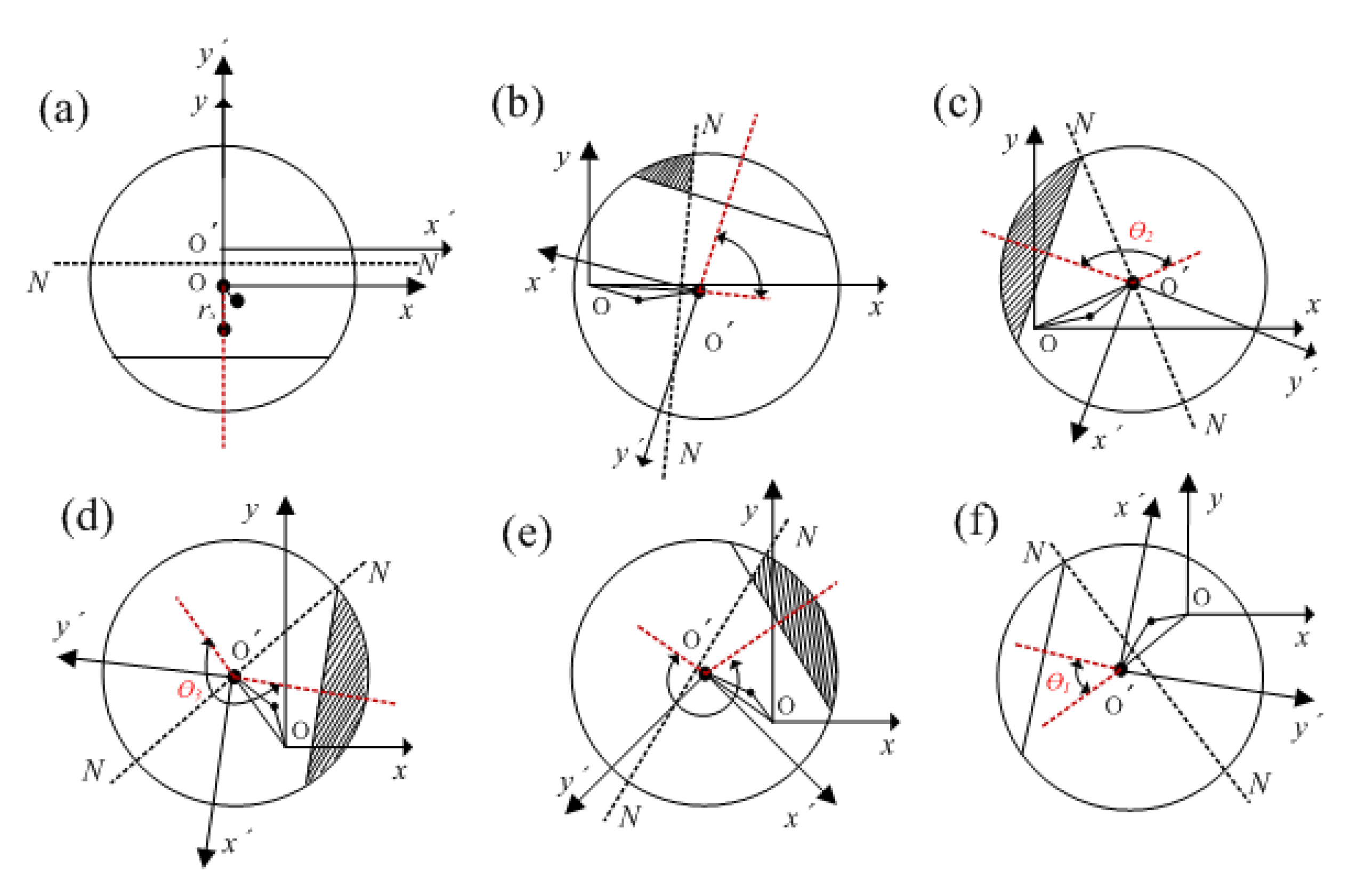
Assuming crack edge is parallel to the fixed X axis at the beginning, and the neutral axis rotates after the shaft starts to rotate as shown in
Figure 2. The angle between displacement vector and rotating
-axis is an important parameter to determine the crack state, which is denoted as
and calculated as [
27]
The crack state is usually determined by the angle difference between rotation and whirl calculated as or , where is the rotation angle of the shaft. However, this difference in the current literature is due to the displacement of rotating shaft which can be obtained only after establishing the complete dynamic model of a rotor system. Thus, the effect of whirl motion is mostly not considered or calculated by a simplified stiffness matrix based on former breathing functions. As the initial bending was taken as one part of the unbalance, the angle was not considered in previous studies. Hence, the breathing functions used before are approximate or simplified models. As a result, the dynamic response calculated by these approximate models is inconsistent with the actual situation.
The examples with and without
are compared here and shown in
Table 2, crack angle is
and other parameters can be found in
Table 1. Three cases of different speed are simulated as Ω = 200 rad/s, Ω = 500 rad/s and Ω = 800 rad/s. At the end of open state of the crack, the angles with initial bending are delayed by 0.03, 0.07 and 0.37 rad, respectively. Hence, the growth rates of these intervals are much bigger than those of rotating speed. The range of fully open state increases to 2.121 from the original result 2.096, the range of fully closed state is still the same as 2.095 and the other two intervals are both reduced from 1.46 to 1.034. Hence, the conversion of crack state becomes much faster than the old model. It’s very interesting that the interval size of the fully closed state remains the same at any rotating speed. But the size of fully open state is increased, while the sizes of other two conversions are reduced and only a half of the size increase of fully open state. Another point that should be noted is that the rotating speed has an important effect on the phase delay of these intervals but has little effect on their sizes.
As
, the crack is fully open and the moment of inertia of closed portion can be obtained from Refs. [
5,
22] as
As
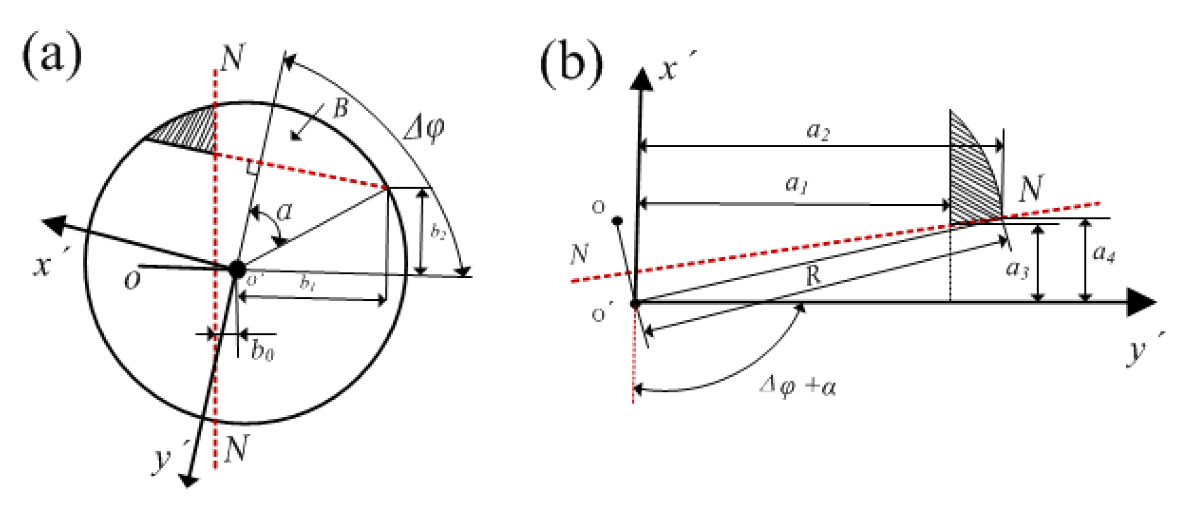
, the crack state transforms from open to closed as shown in
Figure 2b which is described in detail in
Figure 3.
The integration limits for calculating the crack area are given as
The area of the crack portion remaining open is calculated as
where
denotes transverse crack edge,
is the distance from neutral axis to point
. The static moment of the remaining open area is calculated as
According to stresses balance formula
, σ is the normal stress,
A is the area of overall cross-section denoted as
.
is the area of non-crack portion,
Ac is the area of closed portion. Assuming that stress concentration is not considered, the stress balance equation can be transformed by Hooke’s law as
, where
is the distance to neutral axis,
E is Young’s modulus and
ρ is bending radius. Since
, the balance formula changes as
. As we all know, static moment is usually used to calculate the centroid of areas, i.e.,
. Thus, many researchers adopted the centroid formula to calculate the position of neutral axis. Hence, the distance from the neutral axis to point
can be obtained as
Thus the neutral axis in rotating coordinate system
is written as
The integration limits involved are given as
The moments of the closed portion about rotating axes are calculated as
Hence, the overall moment of inertia is given as
where,
Although the change of neutral axis is taken into consideration in a traditional breathing model, the moment of inertia and area of closed portion are not calculated accurately. in Equation (24) is the moment loss because the closed area is reduced by the shift of neutral axis. A similar difference can be found in Equation (21). As a result, the moment of inertia about the rotating axis is smaller than the previous results in the transformation of crack state from open to closed.
As
, the crack is fully closed and the moments of inertia are the same as the case without a crack, given as
As
, the area and static moment of open portion can be calculated as
Hence, the displacement of the centroid is
, and the neutral axis can be obtained as
Similar to the second stage, the angle between rotating
and neutral axis changes from
to
. The moments of inertia are calculated as
As an open portion of the crack region increases, neutral axis gradually moves away from point
o. Therefore, the area still remaining closed is larger than the previous results and the last terms in Equations (27) and (28) are the increases of the moment of inertia. Till then, the moments of inertia about rotating axes are calculated in a whole rotating period. Hence, the moments of inertia about fixed axes can be calculated as [
24]
Then, the area moments of inertia about the centroidal axes which are parallel to the fixed x and y axes during rotation can be calculated by the parallel axis theorem. The displacement of neutral axis is simply calculated as
,
. Hence, the stiffness matrix of the crack cross-section is given by
where,
l is length of the shaft. Many applications of Equation (36) can be found in the literature of dynamical modeling of the crack shaft, and the coupling stiffness is not considered before because it is too small compared with other two stiffness matrices.
Therefore, it can be seen that the initial bending changes the position of the neutral axis and the area of closed portion, playing an important role in determining the breathing functions of a cracked rotor. It should be taken into consideration in vibrational characteristics and stability analysis of rotor systems. As the stability of solution of Equation (1) is the same as that of Equation (2) according to the theory of nonlinear system stability, the solution of Equation (2) is expressed as the product of exponential and periodic components and expanded into the Fourier series by Floquet theory as
where,
is Floquet exponent,
are coefficient vectors. Substitute Equation (37) into Equation (2) and the coefficient vector equation is obtained as
where
is coefficient matrix of harmonics,
P2,
P1,
P0 are constant matrix calculated by
To ensure Equation (38) has nontrivial solutions, the determinant of coefficient matrix should be equal to zero and is expressed as
where
I is a unit matrix,
Z is transition matrix calculated by
Hence, the eigenvalues of matrix Z are usually used as an indicator of the system stability. If all real parts of these eigenvalues are negative, the system can be confirmed to be stable. Otherwise, if one or more of the real parts are greater than zero, the system is unstable. Particularly, if some of these real parts are equal to zero while others are all negative, the system is in a critical state. This method has been widely applied in stability analysis of cracked rotors, and proved to be useful for identification of crack shape parameters and prediction of stable regions. As initial bending is also an important parameter affecting the breathing mechanism of the crack, it is appropriate and necessary to investigate the stability of cracked rotor by this method.
3. Simulation and Discussion
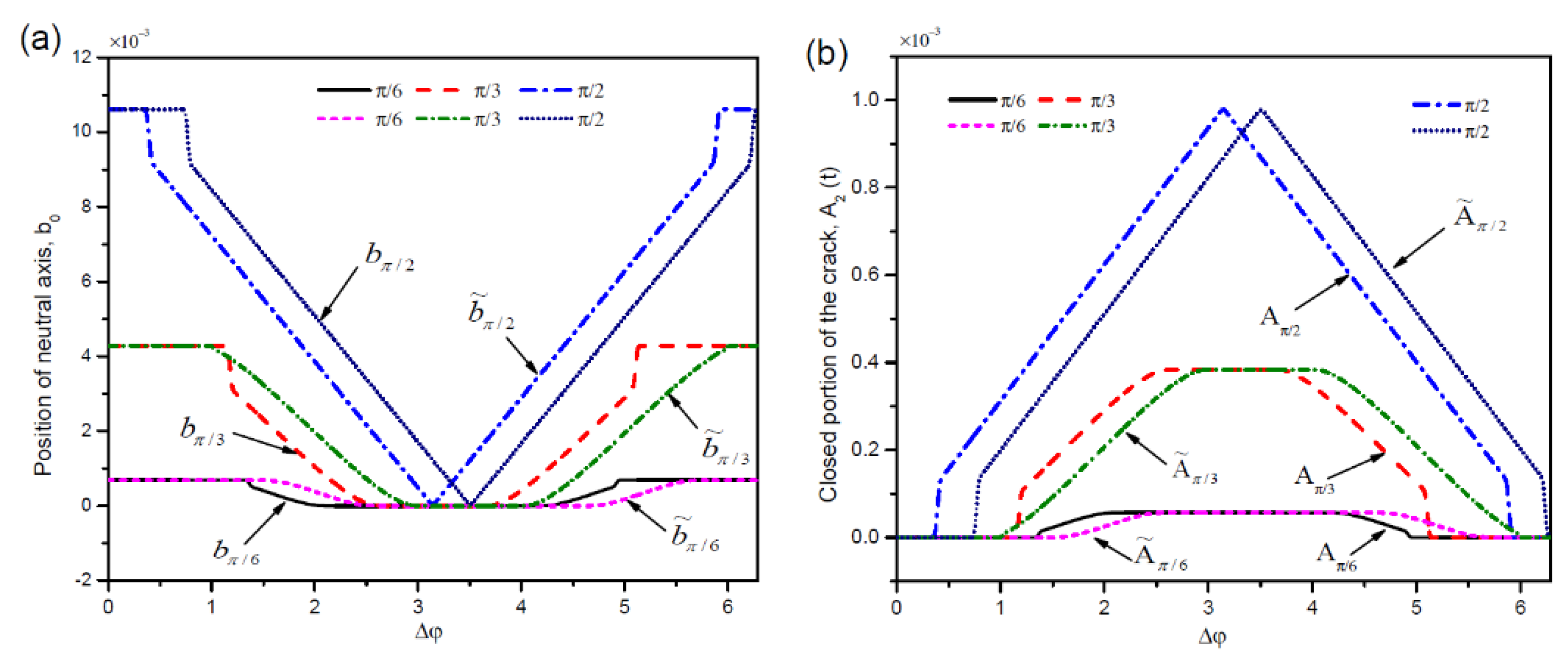
The influence of initial bending on vibrational characteristics obtained by the improved functions is compared with that of a traditional model. Firstly, the displacement of the neutral axis and closed area of the crack region are calculated as
, Ω = 200 rad/s. Three cases of different crack angles
α =
π/6,
α =
π/3 and
α =
π/2 are plotted in
Figure 4. Phase differences of neutral axis position and closed portion area are found to be similar but reverse. In low speed with
α =
π/6, the phase delay is not obvious in the whole rotating period. As the crack grows, the differences become bigger and bigger. When the crack state changes from fully open to closed, the closed portion areas calculated by the improved functions are much smaller than the results obtained by the previous method. Because the change of neutral axis was not considered and approximate arc area was adopted to replace actual closed area in the simplified algorithm.
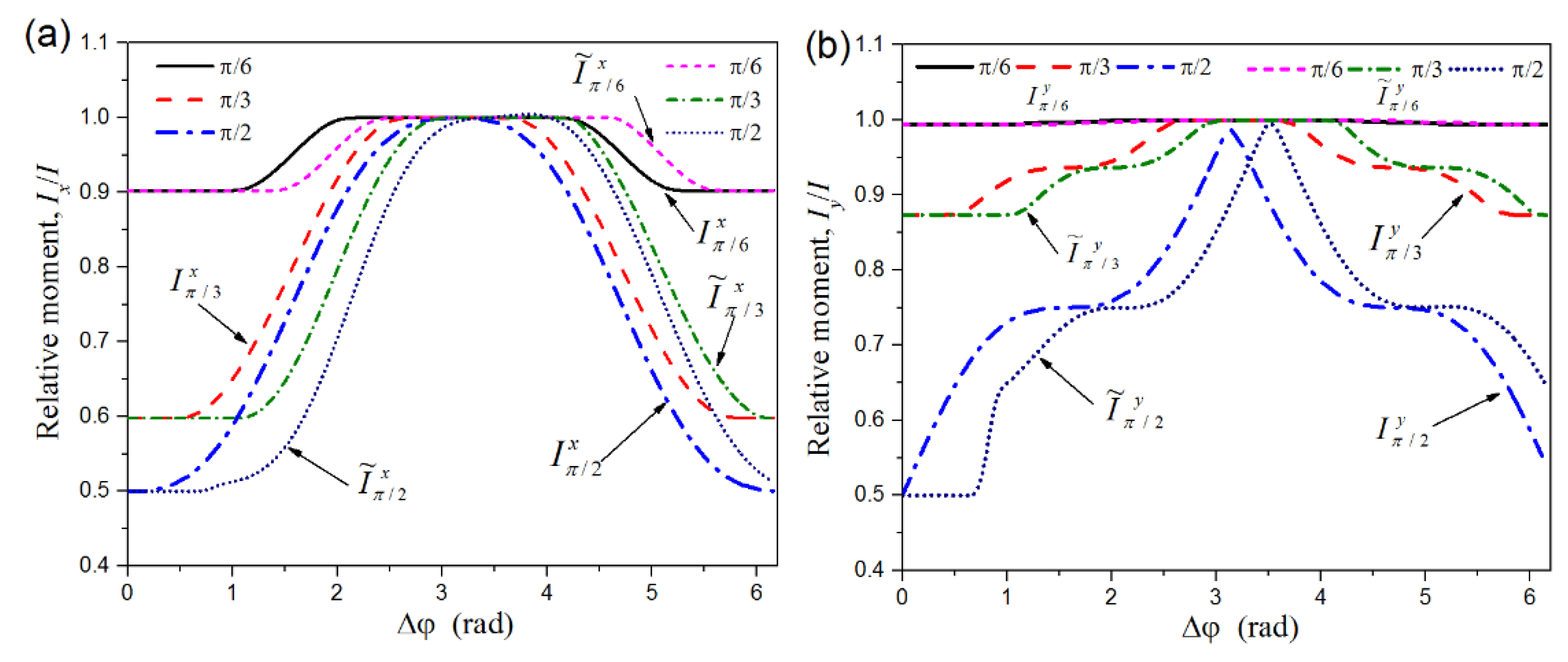
The moments of inertia of overall closed area are plotted in
Figure 5. As
α =
π/6, the relative moment about X axis is delayed by a small phase, and the relative moment about Y axis almost remains the same in the whole rotating period. When the crack angle grows to π/3 or π/2, the delayed phase increases a lot because the crack portion is much bigger than the first case. Especially, the delays in transition of crack state from open to closed are much larger than the delays from closed to open in both
and
directions. The same trend can be found in the moments about fixed axes which are no longer plotted here. Obviously, these varieties are not only a certain phase delay made by the initial bending, but also the range of each crack state as exhibited in
Table 2. There’s an obvious difference between the relative moments about the X and Y axes, the variation curves in the right figure is very closed to the original curves at the midpoint of the both conversion processes. These differences will bring many changes to the dynamic response of the rotor system.
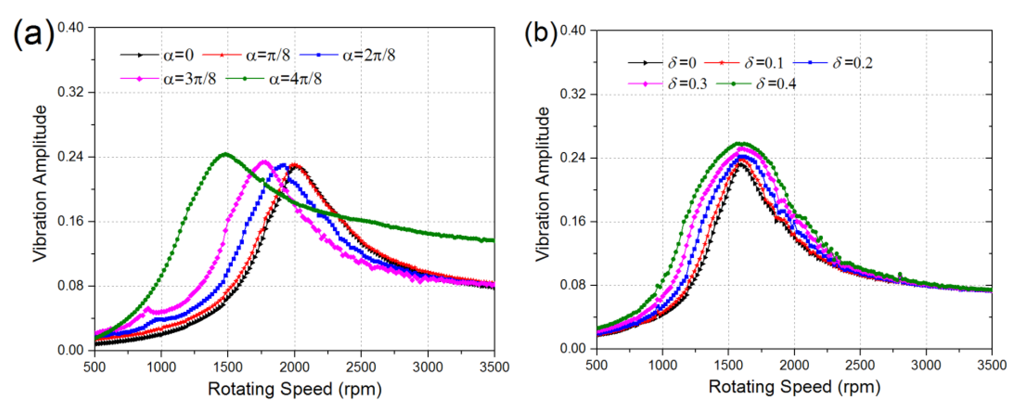
The amplitude-speed diagram with the growth of crack angle and initial bending are plotted in
Figure 6.
Figure 6a shows the change of amplitude along with the growth of speed and crack angle, and the initial bending is not considered in this case. If a value bigger than 0.16 is taken as excessive vibration, the dangerous region is [1780, 2360] when crack is not occurred. The first critical speed of the rotor system is around 2080, and the critical speed should be higher than 1.2 times the working speed to maintain normal operation in practical engineering. Hence, the safe speed of this rotor should be lower than 1730 or higher than 2500 for a flexible shaft. As the crack angle grows to π/8, there is no obvious change. The resonant region changes to [1640, 2120] and [1500, 2260] when the crack angle grows to 2π/8 and 3π/8, respectively. Obviously, the rotating speed entering the resonance region became lower due to the decrease of stiffness, and the vibration amplitude also increases a little. The safe speed of the rotor system is also reduced to 1580 and 1470, and it is easier to become a flexible rotor above the first critical speed. Of course, the safe rotating speed should also be lower than 70% of the next critical speed. Especially, the overall rotating range becomes dangerous region if the crack angle grows to π/2.
When the working speed of rotor system is higher than the critical speed, the rotor has to pass through the resonant region. Thus, many measures are developed to limit the amplitude of the resonant region in project, such as increasing damping, changing the flexible connection and active control device. These issues are not discussed here, but a simple damping program is used to limit the larger amplitude in the resonance area in the numerical simulation.
Figure 6b shows the vibrations of a rotor system with the growth of initial bending and rotating speed, all the results are obtained as the crack angle is π/6. The first curve is almost the same as the first curve in
Figure 6a, because a small crack has little effect on the amplitude. The resonant regions of the other four cases are [1420, 1980], [1320, 2040], [1240, 2120] and [1160, 2160], respectively. A great difference can be found by comparing the vibration amplitudes changing with the growth of crack angle and initial bending. The position of resonant regions has hardly changed while the interval size of the resonant region is enlarged.
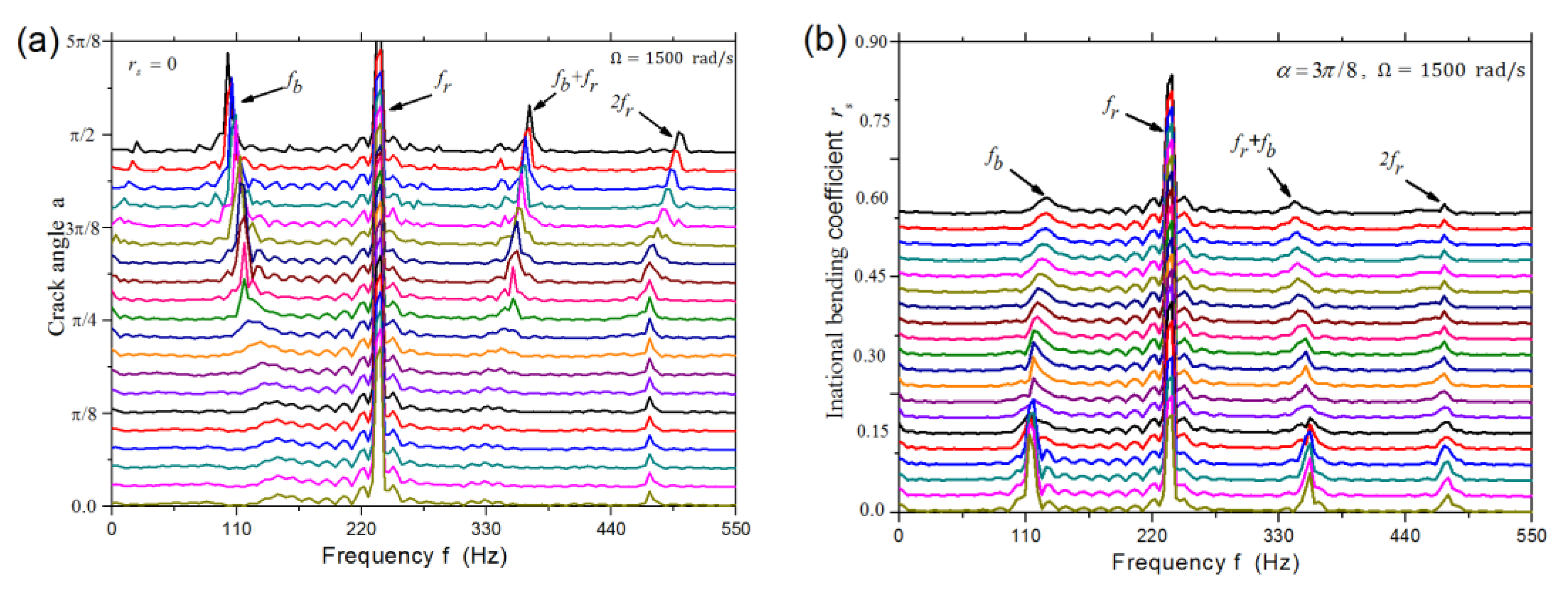
It is interesting to compare the spectrogram of the dynamic response affected by crack angle and initial bending as shown in
Figure 7. As the crack grows, many new frequency components appear continuously besides the excitation frequency. For example, the natural frequency and combined components appears when the crack angle grows to π/4. The natural frequency drops due to the decrease of time-varying stiffness, while the combined and multiple frequencies rise. On the contrary, these frequency components decrease gradually with the increase of initial bending. Finally, only the excitation frequency component remains obvious, which is consistent with the case of unbalanced excitation. Furthermore, the natural frequency increases slightly while the combined frequency drops a little.
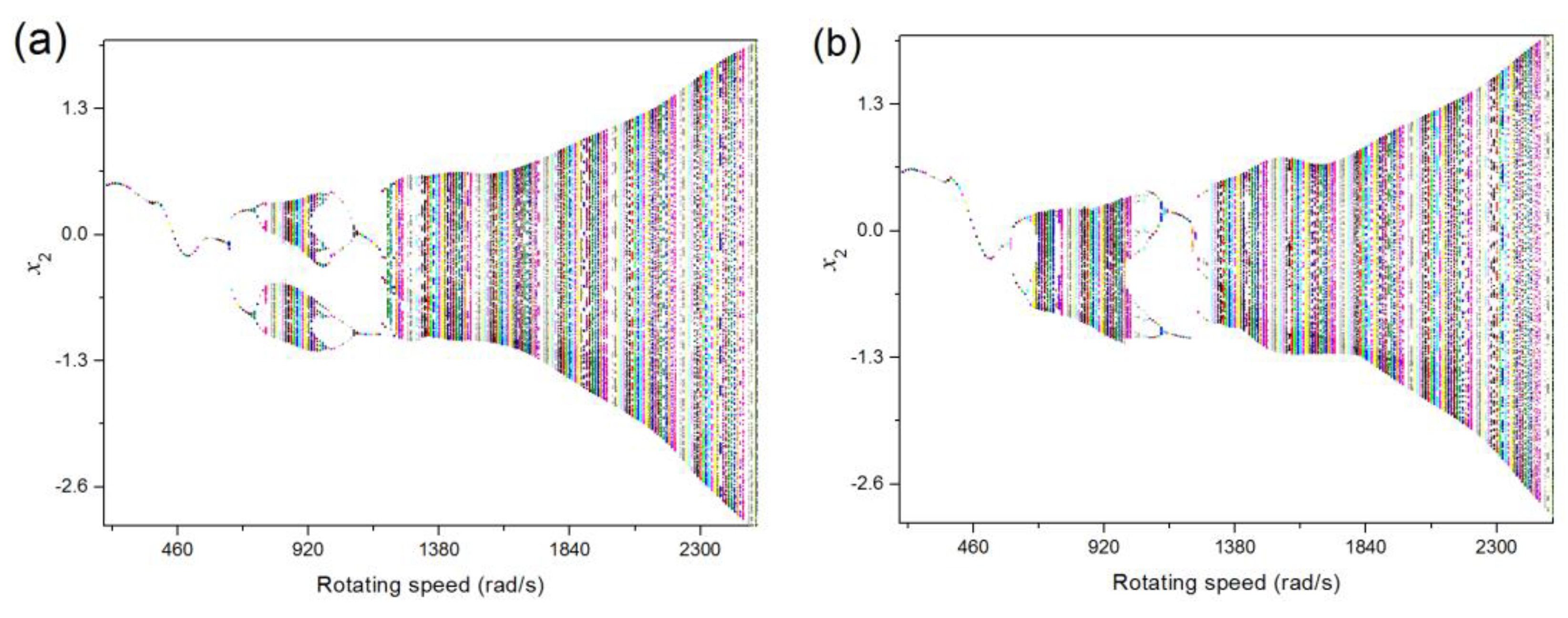
The bifurcations of the two models are plotted in
Figure 8. The biggest difference of the two figures is that the motion of rotor undergoes two period double bifurcations in [600, 800] rad/s when initial bending is not taken into considered. Only the first bifurcation remains and the second bifurcation disappears, then the motion of rotor goes directly into a chaotic response in the right case. This indicates the nonlinearity of the rotor system is increased by the initial bending.
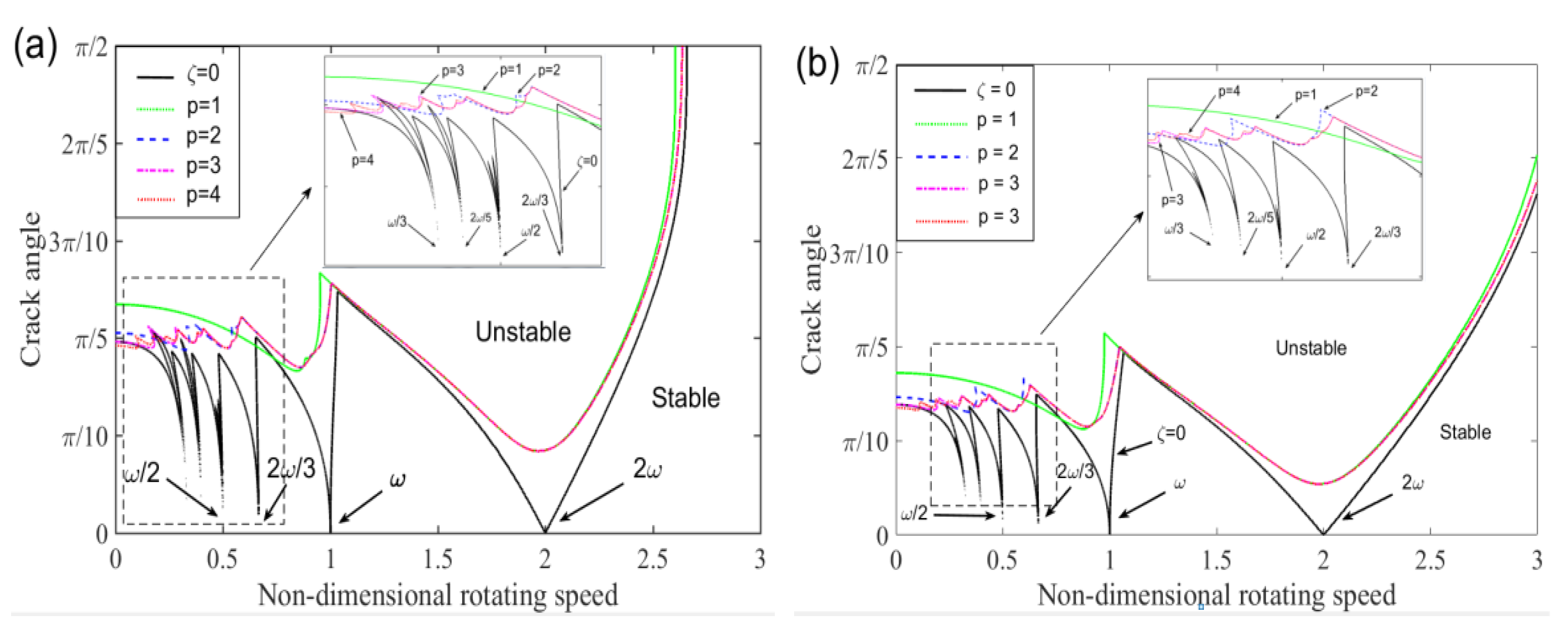
In general, stability regions are reduced by the effect of initial bending. At the beginning of the boundary between stable and unstable regions, the crack angle in the case without initial bending is about 0.2π while the angle is reduced to 0.15π with initial bending. Especially, the stable regions are much smaller than the stable regions without initial bending as rotating speed approaches a multiple or a fractional multiple of the natural frequency. The original tortuous boundary becomes smooth and extends laterally as rotating speed exceeds the natural frequency in
Figure 9b.
Therefore, the rotor system with initial bending or dynamic bending may cause an unstable response or even rubbing fault. Hence, the dynamics of a rotor system with rubbing fault caused by shaft bending has attracted a lot of attentions in recent years. By comparing the dynamic characteristics between the results calculated by the improved model with initial bending and former model, many differences can be found and used for vibration detection, stability analysis and fault diagnosis of rotor systems.


