Concept Paper

Investigation of Surface Modification of 60CrMoV18-5 Steel by EDM with Cu-ZrO2 Powder Metallurgy Green Compact Electrode †

by
Maria Balanou
1,
Panagiotis Karmiris-Obratański
1,2,*,
Beata Leszczyńska-Madej
3,
Emmanouil L. Papazoglou
1 and
Angelos P. Markopoulos
1
1
Laboratory of Manufacturing Technology, School of Mechanical Engineering, National Technical University of Athens, 157 80 Athens, Greece
2
Department of Manufacturing Systems, Faculty of Mechanical Engineering and Robotics, AGH University of Science and Technology, 30-059 Cracow, Poland
3
Department of Materials Science and Non-Ferrous Metals Engineering, Faculty of Non-Ferrous Metals, AGH University of Science and Technology, 30-059 Cracow, Poland
*
Author to whom correspondence should be addressed.
This paper is an extended version of our conference paper published in IManEE 2020: Balanou, M.; Karmiris-Obratański, P.; Papazoglou, E.L.; Galanis, N.I.; Markopoulos, A.P. Surface modification of tool steel by using EDM green powder metallurgy electrodes. IOP Conference Series: Materials Science and Engineering, 2021, Volume 1037.
Machines 2021, 9(11), 268; https://doi.org/10.3390/machines9110268
Submission received: 28 September 2021 / Revised: 26 October 2021 / Accepted: 31 October 2021 / Published: 3 November 2021
(This article belongs to the Special Issue Feature Papers to Celebrate the First Impact Factor of Machines)

Abstract

:
Electrical discharge machining (EDM) is a non-conventional machining process, which is mostly used for machining of difficult-to-cut materials. These materials are often used in engineering applications that require improved surface properties; thus, surface modification is desirable in these cases. In the recent past, it has been observed that EDM is an alternative surface modification process due to migration of material from the electrode to the workpiece surface. Surface modification can be done with powder metallurgy (P/M) electrode as tool. The aim of this work is to examine the surface modification of the tool steel Calmax (Uddeholm) by EDM process using Cu-30 wt.% ZrO2 P/M green compact electrode. The influence of peak current (Ip) and pulse-on (Ton) on the Material Transfer Rate (MTR) and Surface Roughness (SR) was investigated and the surface characteristics were also evaluated by scanning electron microscopy (SEM). The experimental results confirm the material migration from the electrode to the machined surface and show that the higher MTR of 46.5 mgr/min is achieved on the combination of Ip = 9 A and Ton = 25 μs and the Ra varies from 3.72 μm to 7.12 μm.

1. Introduction

In engineering applications, the lifetime of the machined parts is an important topic. The surface failure is mainly caused when the machined parts are exposed to aggressive conditions such as high temperatures and complicated corrosive environments. Therefore, it is necessary to enhance the mechanical and chemical properties of the materials. The improvement of surface properties using conventional methods such as chemical vapor deposition (CVD)/physical vapor deposition (PVD), plasma arc spraying, and ion implantation, requires a high cost of equipment, and the experimental condition is complicated [1]. However, in recent years, Electrical Discharge Machining has been considered as an alternative approach for surface modification [2,3].
EDM is a non-conventional machining process used for machining difficult-to-cut materials and complex geometrical shapes. EDM is used in a lot of industries such as aerospace, automotive, micro-electronics, biomedical, die, and mold production [4]. In this process, electric sparks formed between the electrode and the workpiece separated by dielectric fluid. Τhe electric discharges lead to higher temperatures than the melting point of the materials at the point of discharge. As a result, melting and vaporization of the electrodes take place. Material is removed from both the electrodes due to erosion, and a small crater is created on the tool electrode and the workpiece surface [5,6]. An amount of the molten material is re-solidified at the base of the crater. Then, a layer is formed which is referred to as White Layer (WL). Thus, the formation of this kind of coating has led to the technique of surface modification by EDM. This process is also termed Electric Discharge Coating (EDC).
The machined surface can be modified in different ways, including conventional electrode materials, powder metallurgy (P/M) electrodes, and powder suspended in dielectric fluid [7]. Powder Metallurgy electrodes are technologically feasible for the EDM process, in which the desirable properties of materials can be combined. Chakraborty et al. [8] in their review described the phenomenon of the surface modification by EDC, which is to enhance the surface of the substrate by depositing material from the electrode to the workpiece using a powder metallurgical tool. The tool electrode in this approach is made of compacted powder materials such as TiC, WC, Ti, Ta, Cu, Cr, etc. The tool is crushed in a power press at specific pressures. P/M tools are very sensitive to pulse duration and pulse current, while the influence of powder metallurgical tools on output reactions such as tool wear, MRR, and Material transfer rate is considerably different compared to other traditional electrodes. It is worth mentioning that compared to the conventional electrodes, P/M electrodes discharge higher energies during the machining operation, and they can be mixed at different compaction loads [9,10]. All of the above lead to formation of thicker WL, but it is also associated with increased vulnerability to micro-cracking.
The machined surface can be modified in different ways, which include conventional electrode materials, powder metallurgy (P/M) electrodes, and powder suspended in dielectric fluid [11]. Powder Metallurgy electrodes are technologically feasible for the EDM process, in which the desirable properties of materials can be combined. Powder metallurgy parameters such as compacting pressure and sintering temperature affect the electrode performance [12]. Depending on the sintering temperatures, P/M electrodes are termed green compact, semi-sintered, and sintered P/M electrodes. However, due to the weak bond between the powder particles, the powder metallurgy green compact or semi-sintered electrodes are used to transfer proper materials to create a layer over the workpiece surface.
There is a high scientific interest in the surface modification by EDC using sintered and green PM electrodes [13,14,15]. In more details, Patowari et al. [16] studied the surface integrity of C-40 steel in EDM. WC-Cu P/M green compact tools were used. Material Transfer Rate (MTR), Tool Wear Rate (TWR), and Surface Roughness (SR) were considered as the output responses. It was found that WC was deposited over the work surface and formed a hard and uniform layer. Ton and Ip have significant influence over the process. Gill and Kumar [17] machined a hot die steel (H11) using a Cu-Mn powder metallurgy electrode. The formations of cementite, ferrite, and manganese carbide phases were responsible for the increase in micro-hardness (MH). Gülcan et al. [18] investigated the effect of Cu–Cr and Cu-Mo powder metal tool electrodes on EDM performance outputs. SAE 1040 steel was used as workpiece material. They revealed that electrode material was deposited as a layer over the machined surface, which provides high surface hardness, corrosion, and strong abrasion resistance. Kumar et al. [19] analyzed MTR and SR on OHNS workpiece using CrB2-Cu powder metallurgy electrode. It was established that the desired deposition of the hardened composite layer was found on the workpiece. Chundru et al. [20] studied the surface modification of Ti6Al4V alloy using a TiC/Cu PM electrode made with particle size varying from nano- to micron. They indicated that the high reactive surface area of nanoparticles made far better surface alloying than the other tool electrodes. Hence, better surface roughness and improved hardness values were obtained. Using P/M green compact tools, Mazabhuiya and Rahang [21] performed a reverse pattern generation by EDM on an aluminum 6061 alloy. The experimental results revealed that the surface roughness varied from 1.7 µm to 5.83 µm, which was affected by increased pulse-on time and peak current. Saemah, Kar, and Parowari [22] conducted experiments on surface modification of AA7075 using green P/M Inconel-aluminum electrodes by EDC. Experimental results show that MTR is related to the pulse-on time as Ton increases the MTR decreases. Additionally, EDC is increasing the surface hardness by up to 2.5 times its value.
The literature shows that very few works have been executed for enhancing the surface properties of materials by EDM using a hard ceramic powder to produce a P/M electrode. Based on this, the present work investigates the deposition of zirconia over tool steel by EDM. Zirconia deposition into tool steel makes the material suitable for applications at high temperatures and aggressive environments. As a transition metal oxide, Zirconia (ZrO2) exists in three polymorphic forms, monoclinic (stable up to 1197 °C), tetragonal (stable between temperatures 1197 °C–2300 °C), and the cubic form (stable in temperatures ranges 2300 °C–2750 °C) [23]. Compared to other zirconia, cubic zirconia has higher hardness, strength and toughness, and thermal shock resistance. It has been observed that monolithic zirconia is used in the biomedical industry due to its increased mechanical properties, corrosion-resistant behavior [24], inhibited bacterial invasion, biocompatibility, and hemocompatibility [25,26]. To the best of our knowledge, no available bibliography describes the potential of surface modification by using any form of ZrO2 modified by EDC. The goal of this research is to define the machining conditions by using composite green electrodes. The desirable properties of ZrO2, like mechanical resistance, good refractory capacity, and high chemical stability that its crystalline structure makes ZrO2 a promising candidate material for structural and functional applications [27]. The deposition of zirconium oxide over tool steel would probably form a hard surface layer because of the formation of compounds and phases by reacting with the base material. Therefore, zirconia deposition into tool steel makes the material suitable for applications at high temperatures and aggressive environments. The purpose of this work is the production of zirconia coating over tool steel by EDM. In particular, ZrO2 powder along with Cu powder was used to fabricate a green compact P/M electrode for EDM, with the purpose to transfer the electrode material to the tool steel Calmax (Uddeholm). To the best of the author’s knowledge, this study is the first try to use an oxide, ZrO
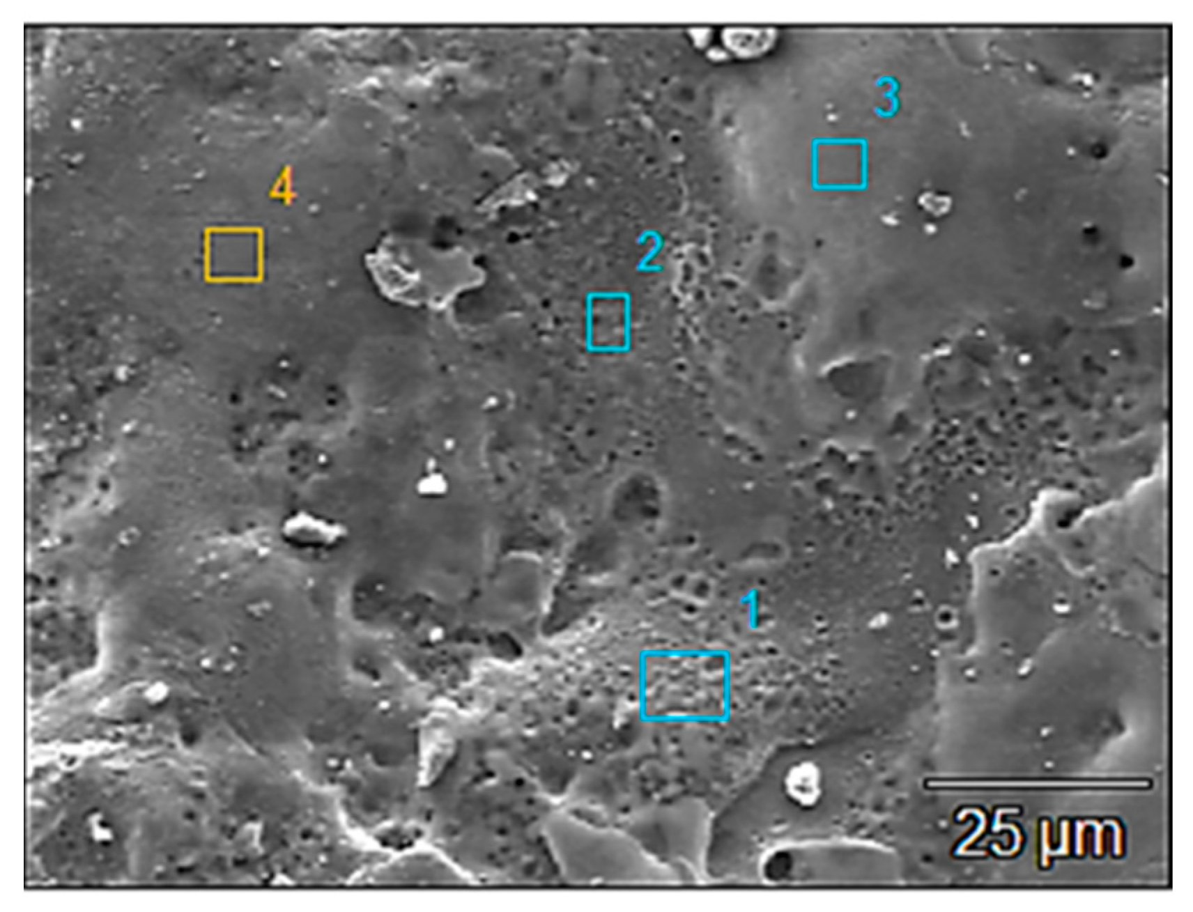
2, to fabricate a P/M electrode for EDM. The effect of peak current (Ip) and pulse-on time (Ton) on the material transfer rate and the surface roughness were investigated. The modified surface was characterized by scanning electron microscopy (SEM) and EDX maps on the cross-sections.

2. Materials and Methods

EDM was used for surface modification of tool steel and the electrode material was used as a green compact electrode consisting of Cu and ZrO2 powders formed by P/M. The Cu and ZrO2 powder mixtures at 70:30 weight ratio were blended and the powder mixture was compacted under 100 MPa pressure using a hydraulic press. The electrode was made in a cylindrical shape with a diameter of 20 mm and a height of 15 mm. It should be mentioned that sintered Cu-ZrO2 P/M electrode was also fabricated. However, it was observed, after a number of tests, that the material deposition was not sufficient. Therefore, a green compact electrode was chosen for the experiments. The bond between the powder particles of the green compact electrode is less, compared to sintered electrodes. Hence, the green compact was used to transfer proper materials.
For experimentation, a die-sinking EDM (AgieCharmillesRoboform 350 Sp) was used. Calmax (Uddeholm) was selected as the workpiece material. This steel is a medium alloyed tool steel. It is commonly used in components subjected to high abrasion such as cold work and plastic injection molding applications that involve high hardness and abrasion resistance. Table 1 shows the chemical composition of the workpiece. The dimension of the workpiece used in the experiments was 85 × 29 × 7 mm. A full-scale series of experiments was carried out and two machining parameters, peak current and pulse-on time, were selected for the experiments. 
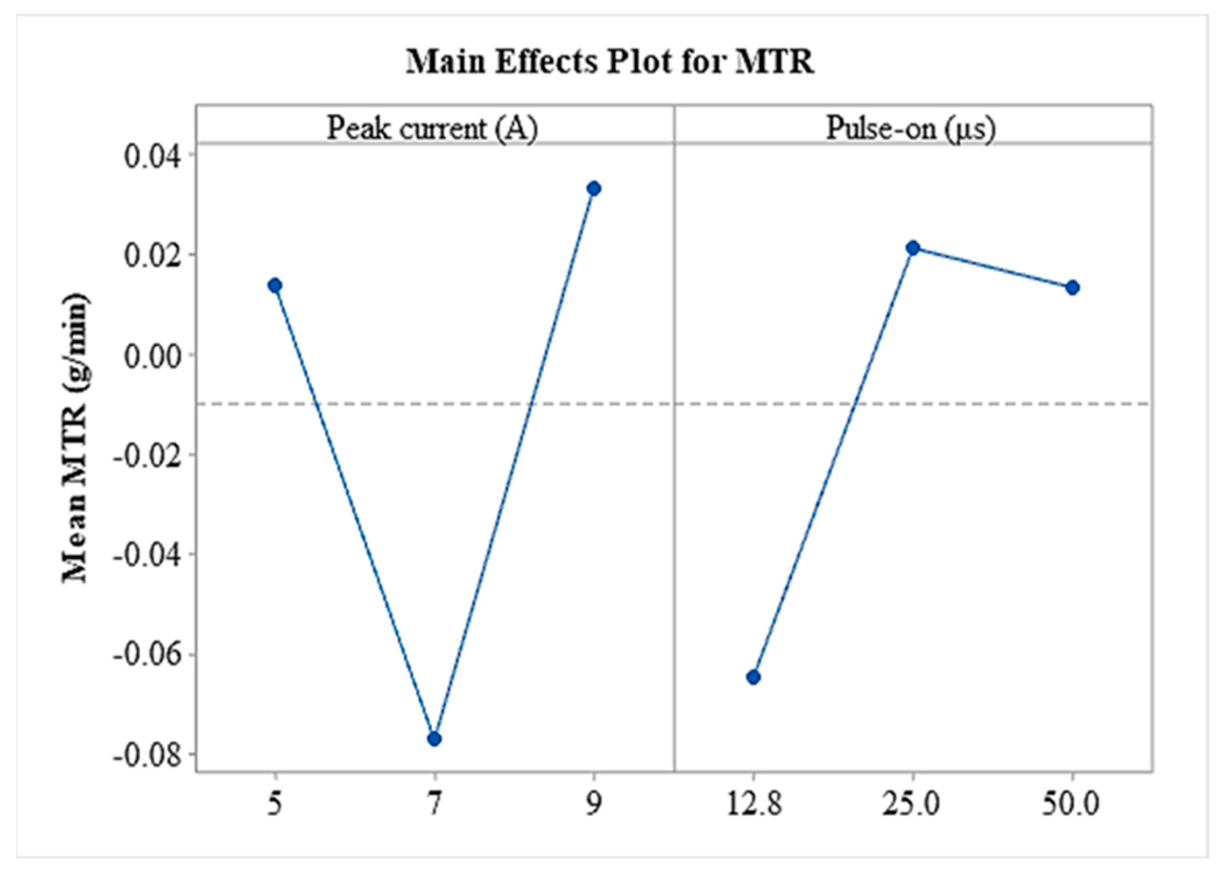
Table 2 gives the selected levels. Each parameter had three levels. Thus, nine experiments were conducted. The peak current varied from 5 to 9 A, and the pulse-on time from 12.8 to 50 μs.
Peak current and pulse-on time were used to study the effect of the material transfer rate (MTR) and surface roughness (SR). The MTR was calculated by measuring the weight difference of the workpiece before and after EDM for a specific machining time, using Equation (1):
MTR = W i     W f t  
where Wi and Wf are the weight of the workpiece before and after the machining (g) and t the machining time (min). SR of the machined surface was measured by TOPO 01P contact profilometer. The roughness parameters that were analyzed are maximum roughness, Rz and, average surface roughness Ra. The cut-off length was set at 2.5 mm with a cut-off length of 8 mm. The machined surfaces, as well as the cross-section, were further investigated using a scanning electron microscope (SEM), Hitachi SU-70, equipped with energy dispersive spectroscopy (EDS) and confocal laser scanning microscopy. The surface topography was measured and depicted by using a VHX-7000 ultra-deep-field microscope (KEYENCE, Mechelen, Belgium), equipped with 20-2000x objective lenses, and based on the Focus Variation Microscopy (FVM) technique. FVM is similar to confocal microscopy, and it is based on a white light LED source that, before it reaches the measuring surface, passes through a semi-transparent mirror and a lens. Then, the reflected light from the focused points returns through the lens, and a beam splitter directs it onto a photonic detector, which registers the geometric and photometric information. That is to say, by employing FVM, colorful 3D surface measurements of high resolutions can be obtained, whilst the small focus depth of a classical optical system and the vertical scanning are combined.

3. Results

The results of MTR and SR parameters are shown in Table 3.

3.1. Surface Characterization

The characterization of the EDMed surface is necessary to determine the surface quality of the material. The EDMed surface is directly related to the discharge energy, and thus, to the machining conditions. During the process, the high heat energy generated by the electric discharges, melts and evaporates the materials at the point of discharge. As a result, a small cavity is created. The majority of the molten material is expelled by the dielectric fluid. However, a small amount of the molten material that cannot be flushed away is re-solidified and is deposited on the machined surface to form a white layer.
SEM micrographs for the machined surface of tool steel at different machining parameters are shown in Figure 1. Some irregularities on the machined surface such as craters, ridges of re-deposited molten metal, debris particles, micro-voids, and micro-cracks have been observed. The high discharge energy affects the size of the craters and also the density of ridges on the machined surface. The increased peak current and pulse-on time generate high heat energy and produce more molten material. Bigger craters and high ridges of re-solidified molten metal are created. Longer pulse-on time allows the plasma column to expand beyond the point of electrical discharge, leading to larger diameter craters. On the other hand, the high peak current results in a deeper crater on the machined surface. The micro-voids are due to the gas bubbles released by the molten material. Micro-cracks appeared due to the residual stresses induced during the process. Residual stresses are generated in the material during EDM because of the phase transformations and the high thermal stresses that exceed the tensile strength of the machined material. The density of micro-cracks depends on the workpiece material, the dielectric fluid, and generally is increased as the discharge energy increases. Lee and Tai [8] have examined the relationship between the cracks density and the machining parameters. Kremer et al. [27] found that ultrasonic vibrations produse less micro-cracks on the surface layer machined by EDM. Their experimental results revealed that higher peak current and shorter pulse-on time can reduce the cracks density. The presence of micro-cracks and micro-voids significantly reduced the fatigue, wear, and corrosion resistance of the material [4].
The effect of the machining parameters on surface topography can also be observed from the 3-D views of the surface topographies plots in Figure 2, where different colors indicate different heights. It can be seen that the surface features, such as size of craters and ridges, are more intense as the peak current and pulse-on time grow higher with the combination of 5 A and 12.8 μs to 9 A and 50 μs.
The EDS analysis of the different regions of the machined surface in Figure 3 confirms the material transfer of the electrode material (Zr and Cu) to the machined surface, as shown in Table 4. The spectrum in Figure 4 for the chemical analysis of the whole area of the machined surface also indicates the presence of Cu and Zr. Additionally, an increase in C appeared due to the kerosene breakdown under high temperature. The high carbon content leads to the formation of carbides. The formation of the carbides contributes to the enhancement of the micro-hardness of the material. The machined surface was further analyzed by EDS mapping of the alloying elements, see Figure 5. A uniform distribution of zirconium and areas rich in Fe and Cu on the machined surface was observed. The uniform distribution of zirconium, unlike copper, implies the creation of compounds by reacting with the base material during the process and re-solidified to form a modified surface.The presence of compounds and phases of Fe and carbides in the tool surface contributes to the enhancement of the micro-hardness of the material.
The cross-section of EDMed surfaces under varying conditions was investigated by SEM analysis, as shown in Figure 6. A non-uniform recast layer was formed on the surface by the re-solidification of the unexpelled molten metal. This inhomogeneity of the recast layer can be justified by the random scattering of electrical discharges on the surface. From Figure 6a–c, it can be seen that the thickness of the white layer depends on the discharge energy. The white layer thickness (WLT) increases as the pulse current and pulse-on time increase. This is attributed to the fact that as the discharge energy increases, more heat is placed on the electrodes, and consequently, more volume of the molten material is produced. The amount of molten material cannot be effectively flushed away by the dielectric fluid and re-solidified on the machined surface to form the WL. Therefore, the thickness of the WL depends on the amount of molten material produced during the process due to high discharge energy [9,20,28]. In particular, the average white layer thickness (AWLT) was smaller when the peak current was 5 A and pulse-on time 12.8 μs, namely 3.57 μm, and thicker when the peak current was 9 A and pulse-on time 50 μs, namely 9.38 μm. More careful investigation of the white layer at the cross-section shows that the surface crack extends in the recast layer, and also the presence of micro-voids was revealed, see Figure 6a,d. Beneath the white layer, the heat affected zone was observed, which was formed due to heating, but not melting.
The white layer seems to consist of a composite structure with white particles in the gray matrix. The EDS mapping (Figure 7) reveals that the white particles are rich in Cu. The composite structure of the white layer appeared due to the localized melting of the steel by the electric sparks and the following mixing with the deposited electrode material. The presence of Zr and Fe at this layer results in the formation of compounds or phases of Fe in the white layer. The machining conditions determine the formation of the compounds that will occur. Figure 8 shows the formation of multiple layers. These layers perhaps appeared because of molten metal ejection from the molten pool and the subsequent solidification into an existing recast layer. The EDS line scan was also applied across to the recast layer. It can be seen that zirconium elemental distribution is steady along the whole line, indicating that Zr has been diffused into the layer. On the other hand, copper decreased at the White Layer/HAZ interface region.

3.2. Material Transfer Rate

MTR is one of the most major performance measures and is influenced by the machining parameters. It was measured by taking the mass difference of the workpiece before and after and dividing the result with machining time, see Equation (1). During EDM, with the increase in peak current, discharge energy increases, resulting in a higher rate of tool electrode erosion and consequently higher MTR. Moreover, as the pulse-on increases, the per-pulse discharge energy also increases, leading to higher erosion as well [12]. Nevertheless, the underlying physical mechanism is far more complicated since material transfer from the electrode and material removal from the workpiece are taking place simultaneously during EDM. Hence, the MTR pertains to the final material transfer balance, and it has to be studied not only as an absolute value, but comparatively as well. The positive values of MTR represent a dominant material removal mechanism that results in an overall material removal, while the negative values imply a dominant material deposition mechanism, and hence, a greater workpiece weight after its machining [22].
In the Main Effects Plot, the mean response values for each level of control parameter or process variable are presented. It is commonly employed to compare the relative impact strength, and the effects of various factors on a certain response index. The sign of the Main Effect Plot indicates the direction of the effect, and namely, whether the average response value increases or decreases in respect to a specific factor, while the magnitude (deflection from horizontal level) pertains to the strength of the impact. Thus, in the following analysis, the Main Effects Plot is utilized as a representative index of how the machining parameters affect the MTR and the SR.
Based on the Main Effects Plots of Figure 9 and the respective results of Table 3, it is deduced that the MTR is stable, with only an exception for the combination of 7 A and 12.8 μs (MTR = −0.2493 gr/min). The positive values of MTR denote that the material removal rate is greater than the deposition rate, while the negative MTR for 7A and 12.8 μs implies the opposite, namely, a higher deposition rate compared with the removal rate. It is important to clarify that for all the machining combinations, irrespective of whether MTR is positive or negative, material deposition is taking place, thus, for all the combinations there is the capability of surface modification. Nevertheless, and since this method is proposed not for material removal, but mainly for surface modification through material transfer from the electrode to the workpiece, MTR values close to zero and even negative can be considered as preferable. In conclusion, aiming at the most efficient surface modification by employing EDM, the machining parameters combinations have to result in the melt of sufficient amount of electrode material, while, at the same time, to allow its deposition on the machined surface.
Analysis of variance (ANOVA) was conducted to found the significance of each parameter, and the results for MTR are shown in Table 5. The ANOVA test was carried out at a 5% significant level. It is noticed that pulse-on time has the lower value of p.

3.3. Surface Roughness of the Machined Surface

As it has been mentioned above, the amount of energy released during the EDM process affects the surface roughness of the machined element. The surface after the machining is covered with overlapping craters, created due to the removal of material, along with irregular flow marks and debris particles. The lower peak current and shorter pulse-on time result in less erosion of the material. This leads to lower surface roughness because of the small-sized craters. Otherwise, higher peak current and longer pulse-on time cause rougher surfaces. The high discharge energy produces large-sized and a high amount of molten metal that gets deposited over the surface. This causes a higher but non-uniform distribution of the deposited molten material into the workpiece, subsequently on a rougher surface [20,29]. Hence, the morphology of the surface includes micro-irregularities, macro-deviations, and surface waviness [30,31].
The surface roughness is measured by the sum of the maximum valley depth and maximum peak height, Rz, and an arithmetical mean of local peaks, Ra. The measured surface roughness parameters, Ra and Rz, for every sample are listed in Table 3. According to the plots in Figure 10a, it can be observed that the mean value of Ra is reduced when the peak current is increased from 7 to 9 A. At this peak current, the high spark energy increases, resulting in a higher amount of molten material and deeper craters. However, the molten material which was not removed from the machining zone is re-solidified at the base of the craters. Therefore, the depth of the crater is decreased, and subsequently, the Ra also decreased. In the pulse-on time main effect plot, it can be noticed that Ra elevates slowly with an increase in pulse-on time from 12.8 to 25 μs and with further increase in pulse-on time, Ra is also increased up to 42.9%. Similar observations are made for the Rz from the main effect plot in Figure 10b. More specifically, the Rz is improved for higher peak current. On the other hand, Rz is increased up to 51.7% with an increase in pulse-on time.
Analysis of variance (ANOVA) was conducted to find the significance of each parameter, and the results for SRa and SRz are shown in Table 6. It is observed that pulse-on time does significantly influence SRa and SRz (p < 0.05).

4. Conclusions

The present study illustrated the use of EDM for surface modification of tool steel Calmax using Cu-ZrO2 P/M green compact electrode. Peak current (Ip) and the pulse-on time (Ton) were used as input parameters. Material transfer rate has been calculated and surface roughness parameters have been measured, namely Ra and Rz. The machined surfaces were investigated using SEM and confocal laser scanning microscopy to study the machined surface characteristics. From the experimental results, the conclusions are summarized as follows:
  • Surface modification of tool steel Calmax was successfully distributed by using Cu-ZrO2 P/M green compact electrode.
  • Average white layer thickness increases as the peak current and pulse-on time increases.
  • The existence of micro-cracks and micro-voids are revealed within the white layer.
  • The white layer consists of a composite structure with white particles (rich in Cu) in the gray matrix (rich in Fe).
  • EDS analysis shows the presence of electrode elements and a large increase in carbon content on the workpiece surface, which confirms the successful deposition of Cu and Zr. Additionally, according to the EDS line scan analysis, Zr has been diffused into the layer.
  • From the ANOVA analysis pulse-on time parameter has significant influence over MTR and SR.
  • The experimental results show that the higher depositions were achieved, i.e., 46.5 mgr.min, for the combination of pulse current 7A and pulse on time 25 μs.
  • Ra varies from 3.72μm for the combination of Ip = 7A and Ton = 50 μs to 7.12 μm for the combination of Ip = 9 A and Ton = 50 μs.

Author Contributions

Conceptualization, E.L.P. and P.K.-O.; methodology, M.B., E.L.P. and P.K.-O.; software, E.L.P. and M.B.; validation, E.L.P. and P.K.-O. and M.B.; formal analysis E.L.P. and M.B.; investigation, B.L.-M., E.L.P. and P.K.-O.; resources, A.P.M. and P.K.-O.; data curation, E.L.P. and M.B.; writing—original draft preparation, M.B., E.L.P. and P.K.-O.; writing—review and editing, B.L.-M. and A.P.M.; visualization, E.L.P. and P.K.-O.; supervision, B.L.-M. and A.P.M.; project administration, A.P.M.; funding acquisition, A.P.M. and P.K.-O. All authors have read and agreed to the published version of the manuscript.

Funding

This research project was partly supported by program “Excellence initiative—research university” from the A.G.H. University of Science and Technology, grant number IDUB: 2035.

Institutional Review Board Statement

Not applicable.

Informed Consent Statement

Not applicable.

Data Availability Statement

The data presented in this study are available on request from thecorresponding author.

Conflicts of Interest

The authors declare no conflict of interest.

Nomenclature

EDMElectrical Discharge Machining
EDCElectrical Discharge Coating
P/MPowder Metallurgy
AWLTAverage White Layer Thicknessμm
EfinElectrode weight after machininggr
EstElectrode weight before machininggr
HAZHeat Affected Zoneμm
IpPulse-on currentA
MTRMaterial Transsfer Ratemm3/min
RaMean Roughnessμm
RzMaximum peak to valley heightμm
SCDSurface Crack Densitym/mm2
SQSurface Quality
STSurface Topography
TonPulse-on timeμs
tmachMahining timemin
WfinWorkpiece weight after machininggr
WstWorkpiece weight before machininggr
WLWhite Layer
ρelElectrode densitygr/mm3
ρwWorkpiece densitygr/mm3
EDSEnergy DispersiveSpectroscopy
SEM Scanning Elec tron Microscopy
FVMFocusVariationMicroscopy
Adj MSAdjustedmeansquares
Adj SSAdjustedsums of squares
Seq SSSequentialsums of squares

References

  1. Chen, Y.F.; Chow, H.M.; Lin, Y.C.; Lin, C.T. Surface modification using semi-sintered electrodes on electrical discharge machining. Int. J. Adv. Manuf. Technol. 2008, 36, 490–500. [Google Scholar] [CrossRef]
  2. Suzuki, T.; Kobayashi, S. Mechanisms of TiC layer formation on high speed steel by a single pulse in electrical discharge machining. Electrochim. Acta 2013, 114, 844–850. [Google Scholar] [CrossRef]
  3. Gill, A.S.; Kumar, S. Investigation of Micro-Hardness in Electrical Discharge Alloying of En31 Tool Steel with Cu–W Powder Metallurgy Electrode. Arab. J. Sci. Eng. 2018, 43, 1499–1510. [Google Scholar] [CrossRef]
  4. Muhammad, P.J. (Ed.) Electrical Discharge Machining (EDM): Types, Technologies and Applications; Nova Science Publishers: New York, NY, USA, 2015. [Google Scholar]
  5. Ho, K.H.; Newman, S.T. State of the art electrical discharge machining (EDM). Int. J. Mach. Tools Manuf. 2003, 43, 1287–1300. [Google Scholar] [CrossRef]
  6. Tsai, H.C.; Yan, B.H.; Huang, F.Y. EDM performance of Cr/Cu-based composite electrodes. Int. J. Mach. Tools Manuf. 2003, 43, 245–252. [Google Scholar] [CrossRef]
  7. Kumar, S.; Verma, A. Surface modification during electrical discharge machining process—A review. Mater. Today Proc. 2020, 46, 5228–5232. [Google Scholar] [CrossRef]
  8. Chakraborty, S.; Kar, S.; Dey, V.; Ghosh, S.K. The phenomenon of surface modification by electro-discharge coating process: A review. Surf. Rev. Lett. 2018, 25, 1830003. [Google Scholar] [CrossRef]
  9. Mussada, E.K.; Patowari, P.K. Characterisation of layer deposited by electric discharge coating process. Surf. Eng. 2015, 31, 796–802. [Google Scholar] [CrossRef]
  10. Naik, S. Study the Effect of Compact Pressure of P/M Tool Electrode on Electro Discharge Coating (EDC) Process. Master’s Thesis, National Institute of Technology, Rourkela, India, 2013. [Google Scholar]
  11. Kumar, S.; Singh, R.; Singh, T.P.; Sethi, B.L. Surface modification by electrical discharge machining: A review. J. Mater. Process. Technol. 2009, 209, 3675–3687. [Google Scholar] [CrossRef]
  12. Samuel, M.P.; Philip, P.K. Power metallurgy tool electrodes for electrical discharge machining. Int. J. Mach. Tools Manuf. 1997, 37, 1625–1633. [Google Scholar] [CrossRef]
  13. Das, A.; Misra, J.P. Experimental investigation on surface modification of aluminum by electric discharge coating process using TiC/Cu green compact tool-electrode. Mach. Sci. Technol. 2012, 16, 601–623. [Google Scholar] [CrossRef]
  14. Chakraborty, S.; Kar, S.; Dey, V.; Ghosh, S.K. Optimization and surface modification of Al-6351 alloy using Sic-Cu green compact electrode by electro discharge coating process. Surf. Rev. Lett. 2017, 24, 1–12. [Google Scholar] [CrossRef]
  15. Chakraborty, S.; Kar, S.; Dey, V.; Ghosh, S.K. Multi attribute decision making for determining optimum process parameter in EDC with SI and Cu mixed powder green compact electrodes. J. Sci. Ind. Res. 2018, 77, 229–236. [Google Scholar]
  16. Patowari, P.K.; Mishra, U.K.; Saha, P.; Mishra, P.K. Surface integrity of C-40 steel processed with WC-Cu powder metallurgy green compact tools in EDM. Mater. Manuf. Process. 2011, 26, 668–676. [Google Scholar] [CrossRef]
  17. Gill, A.S.; Kumar, S. Surface Roughness and Microhardness Evaluation for EDM with Cu-Mn Powder Metallurgy Tool. Mater. Manuf. Process. 2016, 31, 514–521. [Google Scholar] [CrossRef]
  18. Gülcan, O.; Uslan, İ.; Usta, Y.; Çoğun, C. Performance and surface alloying characteristics of Cu–Cr and Cu–Mo powder metal tool electrodes in electrical discharge machining. Mach. Sci. Technol. 2016, 20, 523–546. [Google Scholar] [CrossRef]
  19. Kumar, P.; Sivakumar, M.K.; Jayakumar, N. Surface Modification on OHNS Steel Using Cu-CrB2 Green Compact Electrode in EDM. Mater. Today Proc. 2018, 5, 17389–17395. [Google Scholar] [CrossRef]
  20. Chundru, V.R.; Koona, R.; Pujari, S.R. Surface Modification of Ti6Al4V Alloy Using EDMed Electrode Made with Nano- and Micron-Sized TiC/Cu Powder Particles. Arab. J. Sci. Eng. 2019, 44, 1425–1436. [Google Scholar] [CrossRef]
  21. Mazarbhuiya, R.M.; Rahang, M. Reverse EDM process for pattern generation using powder metallurgical green compact tool. Mater. Manuf. Process. 2020, 35, 1741–1748. [Google Scholar] [CrossRef]
  22. Sarmah, A.; Kar, S.; Patowari, P.K. Surface modification of aluminum with green compact powder metallurgy Inconel-aluminum tool in EDM. Mater. Manuf. Process. 2020, 35, 1104–1112. [Google Scholar] [CrossRef]
  23. Pirvaram, A.; Talebzadeh, N.; Rostam, M.; Leung, S.N.; O’Brien, P.G. Evaluation of a ZrO2/ZrO2-aerogel one-dimensional photonic crystal as an optical filter for thermophotovoltaic applications. Therm. Sci. Eng. Prog. 2021, 25, 100968. [Google Scholar] [CrossRef]
  24. Cubillos, G.I.; Olaya, J.J.; Bethencourt, M.; Cifredo, G.; Blanco, G. Resistance to corrosion of zirconia coatings deposited by spray pyrolysis in nitrided steel. J. Therm. Spray Technol. 2013, 22, 1242–1252. [Google Scholar] [CrossRef]
  25. Kaliaraj, G.S.; Vishwakarma, V.; Kirubaharan, K.; Ramachandran, T.D.D.; Muthaiah, B. Corrosion and biocompatibility beha-viour of zirconia coating by EBPVD for biomedical applications. Surf. Coat. Technol. 2018, 334, 336–343. [Google Scholar] [CrossRef]
  26. Kaliaraj, G.S.; Vishwakarma, V.; Kirubaharan, A.M.K. Biocompatible zirconia-coated 316 stainless steel with anticorrosive behavior forbiomedical application. Ceram. Int. 2018. [Google Scholar] [CrossRef]
  27. Patowari, P.K.; Saha, P.; Mishra, P.K. An experimental investigation of surface modification of C-40 steel using W–Cu powder metallurgy sintered compact tools in EDM. Int. J. Adv. Manuf. Technol. 2015, 80, 343–360. [Google Scholar] [CrossRef]
  28. Kremer, D.; Lebrun, J.L.; Hosari, B.; Moisan, A. Effects of Ultrasonic Vibrations on the Performances in EDM. CIRP Ann. 1989, 38, 199–202. [Google Scholar] [CrossRef]
  29. Tijo, D.; Kumari, S.; Masanta, M. Ceramic-metal Composite Coating on Steel Using a Powder Compact Tool Electrode by the Electro-Discharge Coating Process. Silicon 2018, 10, 1625–1637. [Google Scholar] [CrossRef]
  30. Kar, S.; Chakraborty, S.; Dey, V.; Ghosh, S.K. Optimization of Surface Roughness Parameters of Al-6351 Alloy in EDC Process: A Taguchi Coupled Fuzzy Logic Approach. J. Inst. Eng. Ser. C 2017, 98, 607–618. [Google Scholar] [CrossRef]
  31. Balanou, M.; Karmiris-Obratański, P.; Papazoglou, E.L.; Galanis, N.I.; Markopoulos, A.P. Surface modification of tool steel by using EDM green powder metallurgy electrodes. IOP Conf. Ser. Mater. Sci. Eng. 2021, 1037, 012014. [Google Scholar] [CrossRef]
Figure 1. SEM micrographs of the machined surface (a) Ip = 5 A and Ton = 12.8 μs, (b) Ιp = 7 A and Ton = 25 μs and (c) Ιp = 9 A and Ton = 50 μs.
Machines 09 00268 g001
Figure 2. Surface topography of the machined surface based on the FVM for (a) Ip = 5 A, Ton = 12.8 μs and SRa = 3.72 μm, (b) Ιp = 7 A, Ton = 25 μs and SRa = 4.89 μm and (c) Ip = 9 A, Ton = 50 μs and SRa = 6.29 μm.
Machines 09 00268 g002
Figure 3. SEM micrograph of the machined surface for Ip = 5 A and Ton = 12.8 μs.
Machines 09 00268 g003
Figure 4. SEM micrograph and EDS spectrum of machined surface for Ip = 5 A and Ton = 25 μs.
Machines 09 00268 g004
Figure 5. EDS mapping of the machined surface for Ip = 5 A and Ton = 12.8 μs.
Machines 09 00268 g005
Figure 6. Cross-section of EDMed surfaces showing the thickness of the white layer: (a) Ip = 5 A, Ton = 12.8 μs and AWLT = 3.57 μm, (b) Ιp = 7A, Ton = 50 μs and AWLT = 6.58 μm, (c) Ip = 9 A, Ton = 50 μs and AWLT = 9.38 μm and (d) Ip= 9 A, Ton = 50 μs.
Machines 09 00268 g006
Figure 7. EDS mapping of the cross section of the machined surface for Ip = 9 A and Ton = 50 μs.
Machines 09 00268 g007
Figure 8. SEM micrographs of the cross section of the machined surface for Ip = 5 A and Ton = 12.8 μs.
Machines 09 00268 g008
Figure 9. Main effect plot of the MTR.
Machines 09 00268 g009
Figure 10. Main effect plot (a) for Ra, and (b) for Rz.
Machines 09 00268 g010
Table 1. Chemical composition of work piece material Calmax (Uddeholm).
CSiMnCrMoVFe
Typical Analysis %0.60.350.84.50.50.2Balance
Table 2. Inputparameters.
ParametersLevel 1Level 2Level 3
Peak Current Ip (A)57 9
Pulse-on time Τon (μs)12.82550
Duty Factor (η)0.5
Dielectric Fluid Kerosene
Table 3. Experimental results.
Exp. No.Ip (A)Ton (μs) MTR   ( g min ) Ra (μm)Rz (μm)
1512.80.02283.7261.08
25250.00724.3488.04
35500.01176.27101.96
4712.8−0.24935.7599.93
57250.01034.8984.8
67500.00827.12129.14
Table 4. Detailed EDS analysis of the machined surface for Ip = 5A and Ton = 12.8 μs corresponding to Figure 3.
Weight%ZrCu
Point 11.378.24
Point 23.9515.90
Point 32.0210.65
Point 40.4258.78
Table 5. ANOVA analysis for MTR.
Source DFAdj SSAdj MSF-ValueP-Value
Ip (A)10.0005720.0005720.060.817
Ton (μs)10.0065090.0065090.660.446
Error60.0588140.009802
Table 6. ANOVA analysis for SRa and SRz.
Source DFAdj SSAdj MSF-ValueP-Value
SRa
Ip (A)10.29930.29930.580.473
Ton (μs)16.68596.685913.070.011
Error60.0588140.009802
SRz
Ip (A)17.877.870.030.871
Ton (μs)12574.512574.519.450.022
Error61634.43
Publisher’s Note: MDPI stays neutral with regard to jurisdictional claims in published maps and institutional affiliations.

