1. Introduction
The constant increase in natural catastrophic events such as earthquakes, fires, and hurricanes has pushed research towards the development of robotic devices capable of performing patrolling and rescue tasks, as discussed, for example, in References [
1,
2]. BIGDOG [
3], Momaro [
4], DOGGO [
5], and Mini-Mini Cheetah [
6] are valuable design examples within the rich literature on the topic. Some designs have also evolved into commercial products such as SPOT (Boston Dynamics), ANYMAL (ANYbotics), and AlienGo (Unitree Robotics), as reported, for example, in Reference [
7]. The intended operation tasks for the abovementioned robots consist mainly on identification of the environment, inspection of key features, detection of dangerous materials, and locomotion on unstructured environments with the presence of obstacles of different sizes and shapes. In this context, legged locomotion has been found to be the most effective strategy, since it allows us to overcome obstacles, whose size is comparable with a leg size. Nevertheless, legged locomotion is quite challenging from design and operation viewpoints, as it is requiring high-level multidisciplinary knowledge in mechanics, control, programming, and sensing, as also outlined in Reference [
8].
Multiple-legged locomotion has attracted specific attention from the research team led by Professor Carbone in the last 15 years, also aiming at developing proper design procedures and innovative designs for cost-oriented and user-friendly solutions in specific locomotion tasks, as well as proposing locomotion architectures ranging from biped to hexapod, as reported, for example, in References [
8,
9,
10,
11,
12,
13,
14].
This paper proposes the design of a four-legged robot for exploration and rescue tasks as a challenging mechatronic concept to be developed as a master students teamwork within the classes of Mechatronics delivered at University of Calabria, Italy. Accordingly, this paper proposes a general design procedure to address the specific technical challenges of quadruped locomotion. Moreover, it also aims at demonstrating the effectiveness of a “learning-by-doing” teaching approach where master students are stimulated to gain in-depth knowledge on a challenging multidisciplinary topic, learning skills and expertise which is often difficult to master through other traditional teaching approaches.
With the above premise, this work describes the key design and operation challenges on the development of a full quadruped robotic prototype including all hardware, control, sensors and software components. Namely, in this paper,
Section 2 describes the attached problem and the design steps towards a conceptual design. Then,
Section 3 provides kinematics modeling and analyses for a proper type and size synthesis of a leg.
Section 4 addresses the dynamic modeling and analyses also aiming at a proper selection and sizing of the required actuators. The last section describes the manufacturing of a proof-of-concept prototype including all hardware and sensory components. This is followed by a description of the proposed control hardware and software followed by results of preliminary tests, which have been carried out for validating the feasibility and effectiveness of the proposed design choices.
2. The Attached Problem and the Proposed Conceptual Design
Inspection and rescue tasks are characterized by several design requirements and constraints, which are briefly outlined, for example, in References [
1,
2]. Accordingly, it is fundamental to undergo a systematic design approach for being able to fulfil the expectations and needs of specific application tasks.
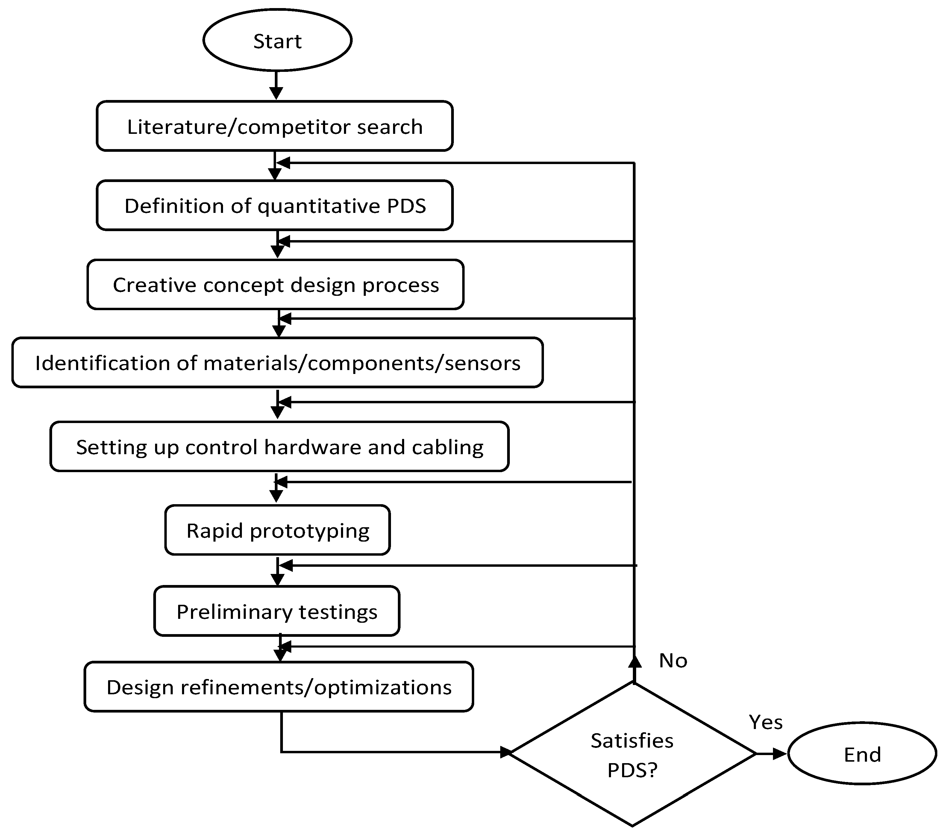
A feasible design procedure has been defined through key design steps as outlined in the flow-chart of
Figure 1. In particular, the very first step consists of an in-depth analysis of the available literature for identifying quantitative data regarding the prescribed design requirements and constraints. These quantitative data can be collected into a product design specification (PDS) table, as reported, for example, in
Table 1. This first step can be followed by a team brainstorming session for identifying the main challenges and potential design concepts/solutions, which can be technically allow the prescribed product design specification. Quantitative and qualitative comparisons among multiple design concepts or choices may lead on reaching a consensus on a specific design concept. The next design step consists of quantitative calculations (i.e., kinematics and dynamics modeling) and software aided simulations aiming at identifying the most appropriate materials, hardware components, sensors as well as for performing mechanism type and size syntheses.
The specific proposed attached problem is providing a valuable engineering design learning benchmark, as it requires us to address several key challenging theoretical and practical aspects, including theoretical kinematics and dynamics aspects. Furthermore, the proposed design procedure and approach can be understood as a valuable general-purpose learning-by-doing educational means, which can be used and replicated as an effective learning approach for mechanical engineering masters’ students, who are engaged and stimulated towards gaining complex theoretical, simulation, operation, and experimental testing skills with the development of a complex mechatronic system. Furthermore, the proposed specific design solution has the merit and novelty to propose a topology with just 2-dofs kinematic architecture for each leg, in combination with a crank and rope driving mechanism and a balancing spring. This proposed solution is demonstrated to be a very effective solution for achieving dynamic walking and trotting gaits while keeping a reasonable cost-oriented and user-friendly design.
This phase might require multiple iterations until a proper solution is confirmed to fulfil design performance expectations based on the product-design-specifications checklist. This phase can be conveniently followed by a rapid prototyping phase in which one can achieve preliminary experimental proof of the proposed design concept. This phase might require reiterating the whole design process in case any key performance results are below the expectations. Moreover, there might be multiple design refinement/optimization phases until the proposed design reaches its final stage.
3. Kinematic Analysis
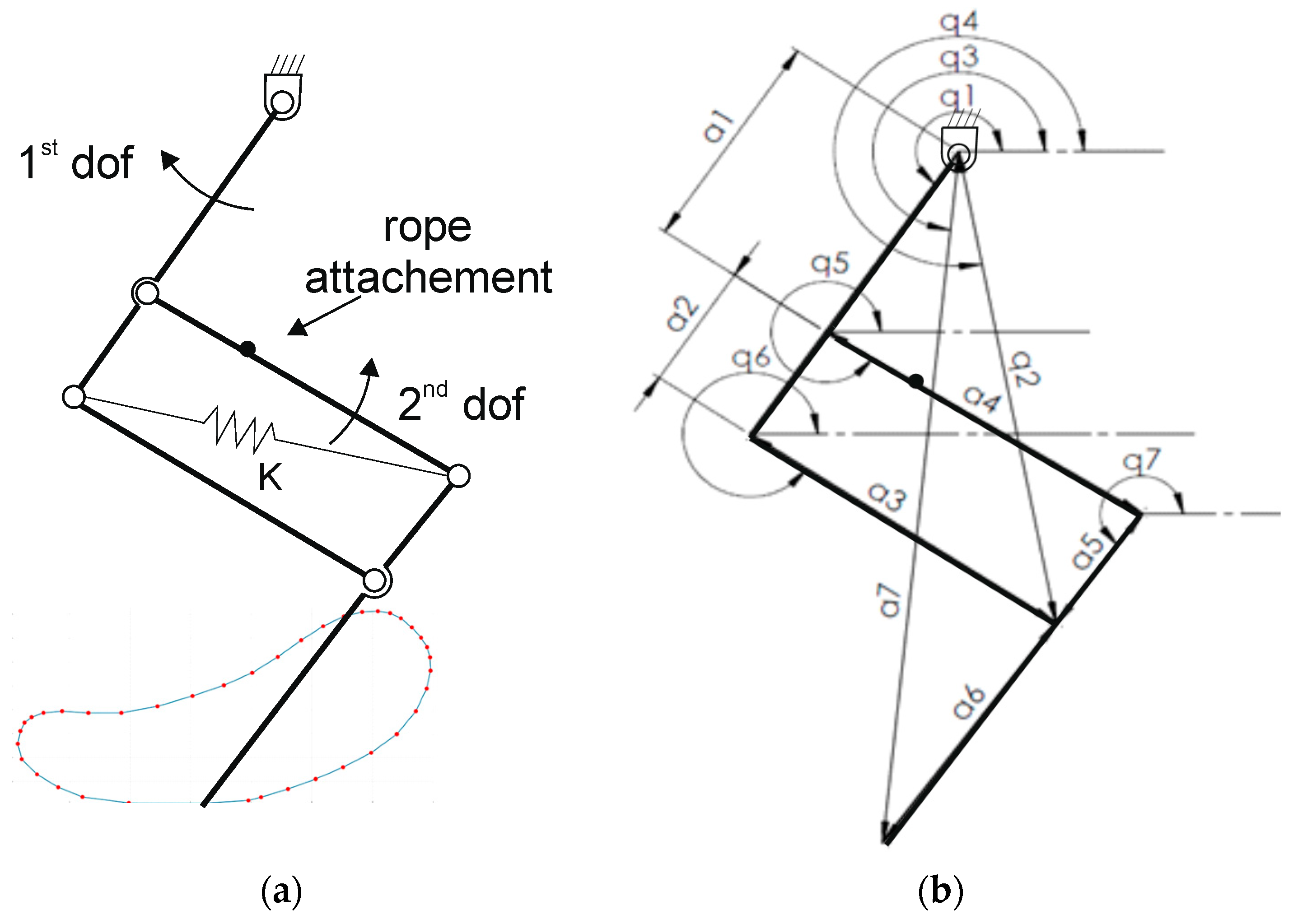
As shown in
Figure 2, a four-bar mechanism is used to actuate the robot’s leg, operated by using a crank and a rope. The mechanism is obtained through the assembly of four links with revolute joints. The degrees of freedom of this kinematic mechanism are two, one relating to the rotation of the crank connected to the frame with an additional revolute joint connecting to the rope that activates the movement of the four-bar mechanism, as reported in
Figure 2a. In this section, the direct kinematics model is developed and solved by following the design variable that are reported in
Figure 2 and
Table 2. This model provides the position of the paw in terms of X and Y coordinates once the values of the joint variables q
1 and q
2 are assigned.
The direct kinematics model was developed by using the closing polygon method or close-loop method [
14], identifying three of the possible polygons in the kinematic scheme of
Figure 3.
where a
1, a
2, a
3, a
4, a
5, and a
6 are the dimensions of the various links that make up the kinematic scheme; a
7 is the virtual segment that traces the position of the point of contact with the ground; and q
2 indicates the length of the rope that activates the four bar mechanism. A Cartesian reference frame was chosen, as reported in
Figure 4. Accordingly, one can consider the projections along X and Y axes of the vector Equations (1)–(3). Using the abovementioned projections, it is possible to obtain a system of six equations in six unknowns, namely q
3, q
4, q
5, q
6, q
7, and a
7, as reported in Equation (4).
The system of Equations (4) was solved by means of the Matlab symbolic calculation software, in order to obtain the end-effector positions as function of the input angle,
, and the length of the rope,
.
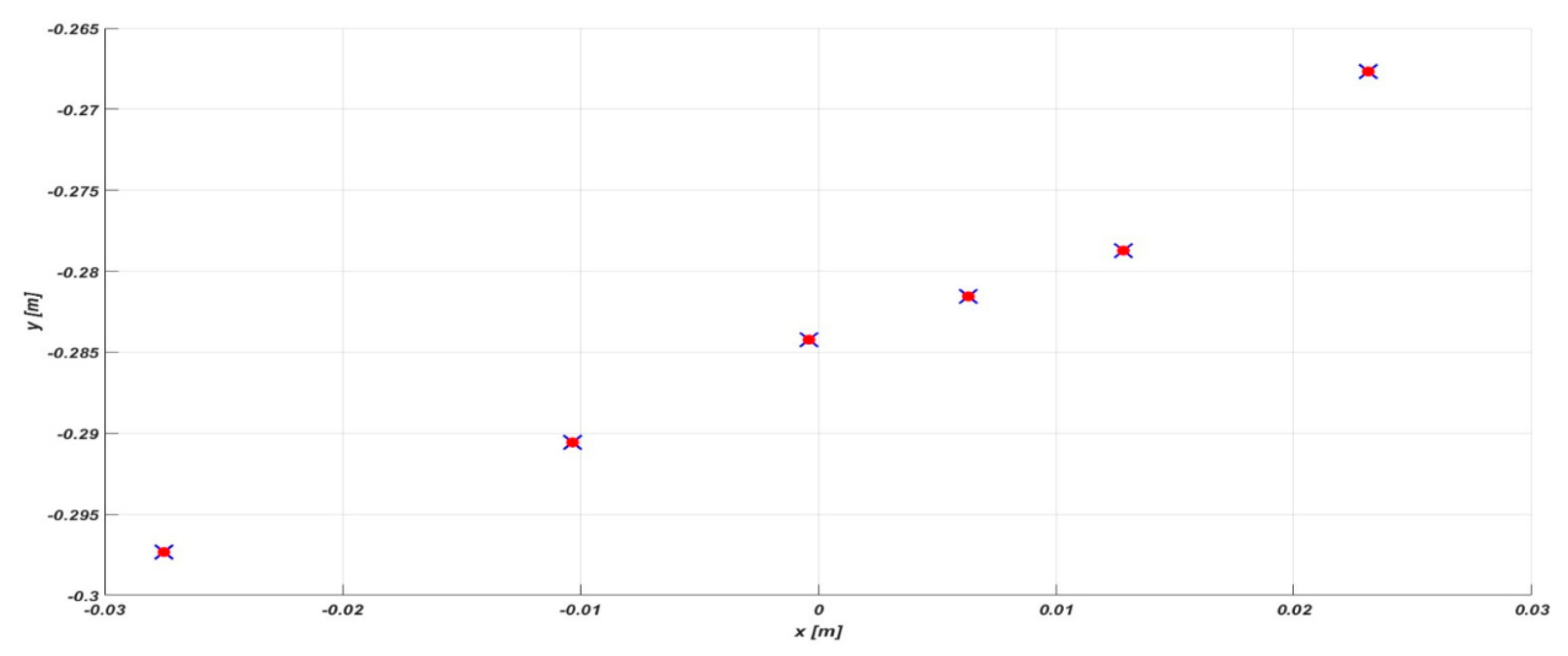
By solving the system of Equation (4), it is possible to obtain the positions
and
, as indicated in Equations (5) and (6). These equations represent the X and Y positions plotted by the virtual link
indicated in
Figure 3. The validation of the kinematic model developed in this section was carried out by comparing the respective values obtained through a multi-body model created on SimMechanics.
Figure 3 shows the overlap of the points obtained from the solved kinematic model Equation (4) and the points extracted from the multi-body model created on the SimMechanics simulation software. Thus, this validates the correctness of the proposed analytical model.
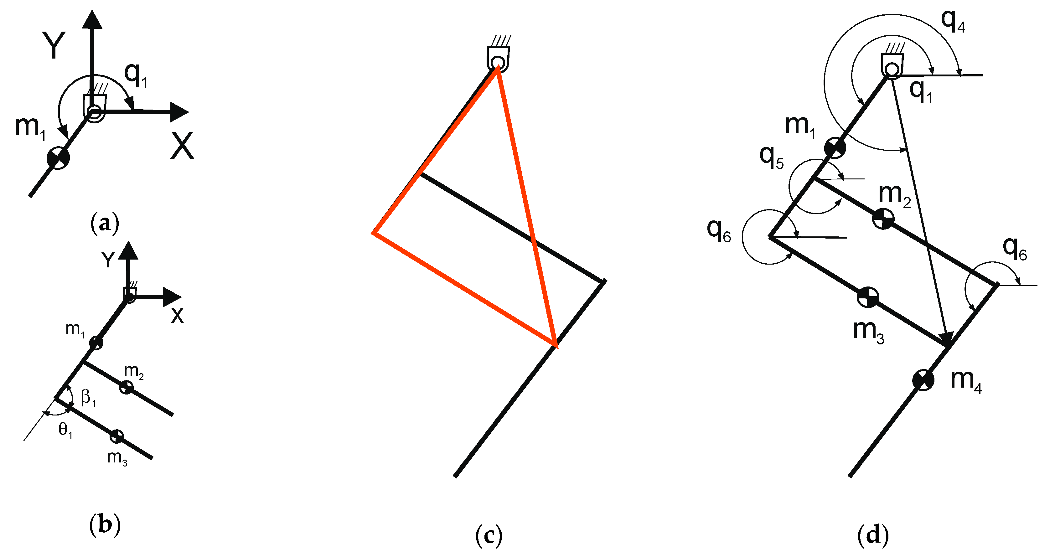
Figure 4 shows the geometric relationships used to evaluate the position of the centers of mass of the links that compose the whole mechanism. The position of the mass m1 coincides with the center of mass of the link of length l
1 = a
1+a
2, and the position of the center of mass
can be obtained as follows:
where c
1 and s
1 stand for cos(q
1) and sin(q
1), l
1 = a
1+a
2 is the length of the first link, and
indicates the position of the center of mass m
1 along the components X, Y and Z. The position of the masses m
1 and m
2 indicated in
Figure 4b is obtained starting from the geometric considerations referring to the triangle shown in
Figure 4c. By applying Carnot’s theorem, it is possible to obtain the angle θ
1 as a function of the length of the segment q
2 as follows:
where q
2 is the length of the segment in
Figure 5c, a
3 is the length of link three in
Figure 4c, and
is the angle formed by links one and three visible in
Figure 5c. Once the angle
is known, it is possible to obtain the angle
shown in
Figure 4b and obtain the position of the centers of mass
,
, and
as follows:
where a
3, a
4, a
5 and a
6 are the lengths of the segments visible in
Figure 5c. The position of the center of mass m4 in
Figure 5d is determined by considering that geometric constraint is given by the parallelism of link 1 and link 4. Accordingly, the angles q
1 and q
7 are always kept at the same value.
4. Dynamic Analysis
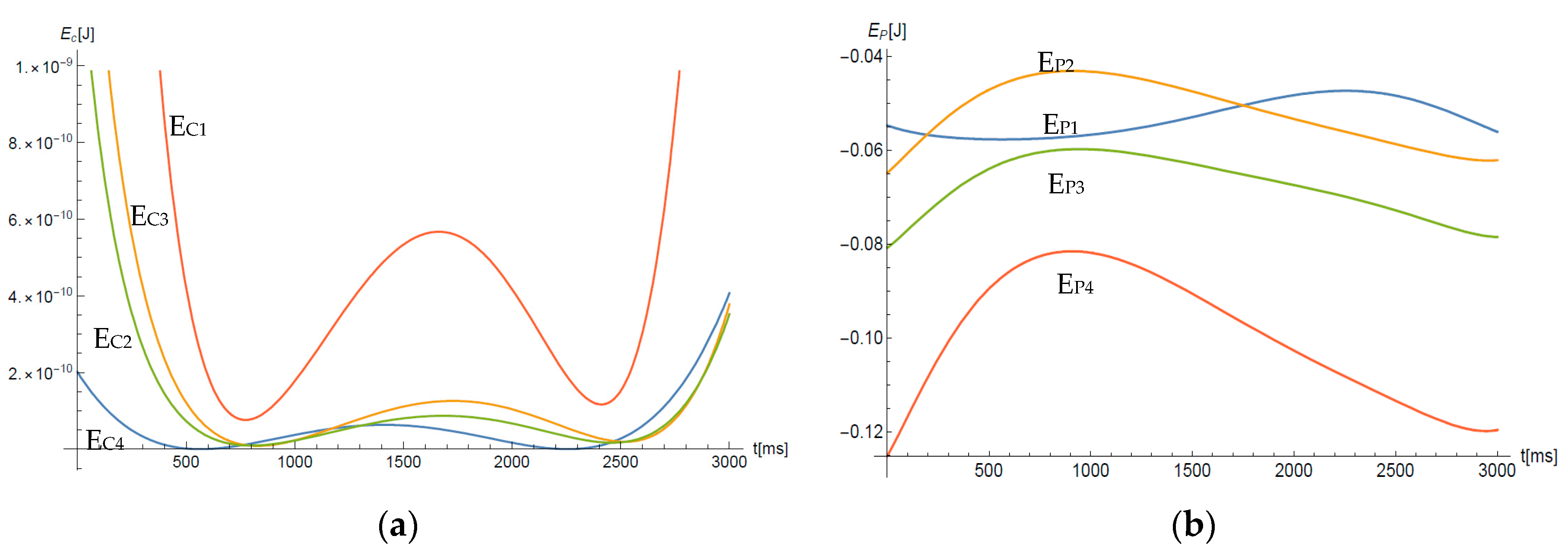
A dynamic analysis was developed for the kinematic model that operates the robot paw for making a suitable choice of servomotors. The approach used is the energy approach as based on the Euler–Lagrange formulation. Starting from Equations (7) and (9)–(11), the kinetic and potential energy of the kinematic scheme in
Figure 2 was evaluated, taking into account the presence of a spring installed at the diagonal of the four bar (a
2, a
3, a
4, and a
5), between the joints 7 and 6 of
Figure 5. This spring has the function of a gravity balancing element, useful to bring the paw back into contact with the ground when the rope corresponding to the segment has stretched q
2, as shown in
Figure 5.
The kinetic and potential energy values shown in
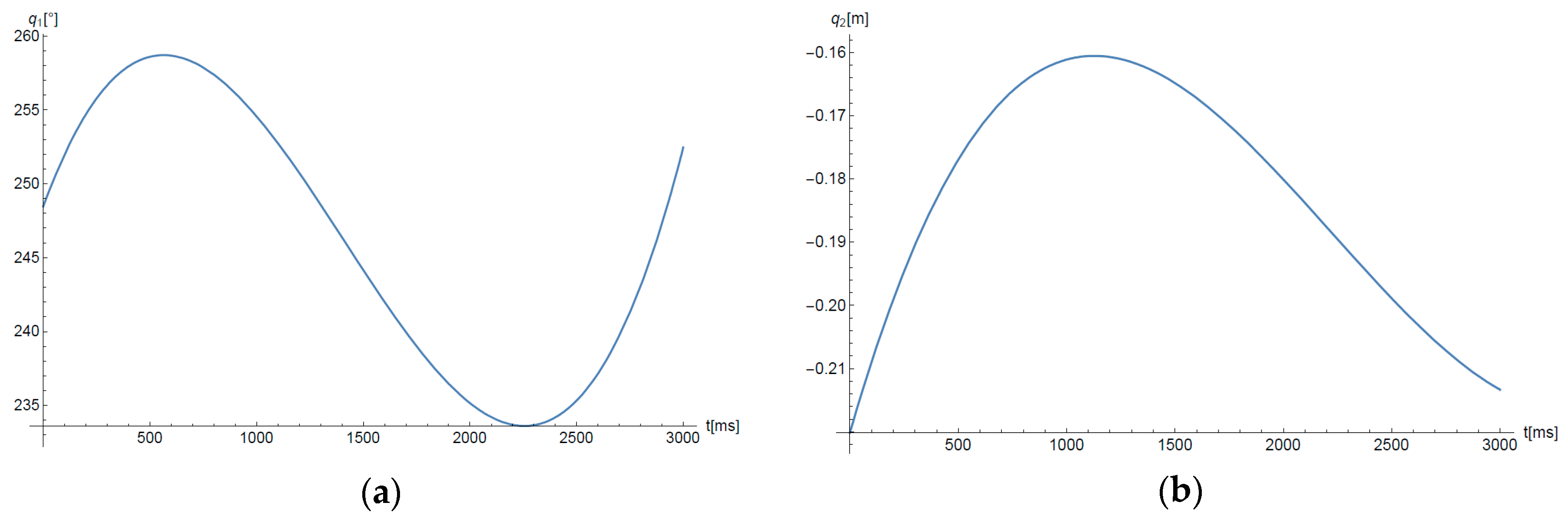
Figure 6a,b were obtained by assigning to the joint variables q
1 and q
2 of the third order polynomial paths, so as to trace a closed circular path in the paw–ground contact area. The assigned trajectories are shown in
Figure 7 and
Figure 8, where one can note a maximum lift of about 0.22 m and a maximum step size of about 0.14 m for a maximum leg size of about 0.5 m at nominal standing configuration.
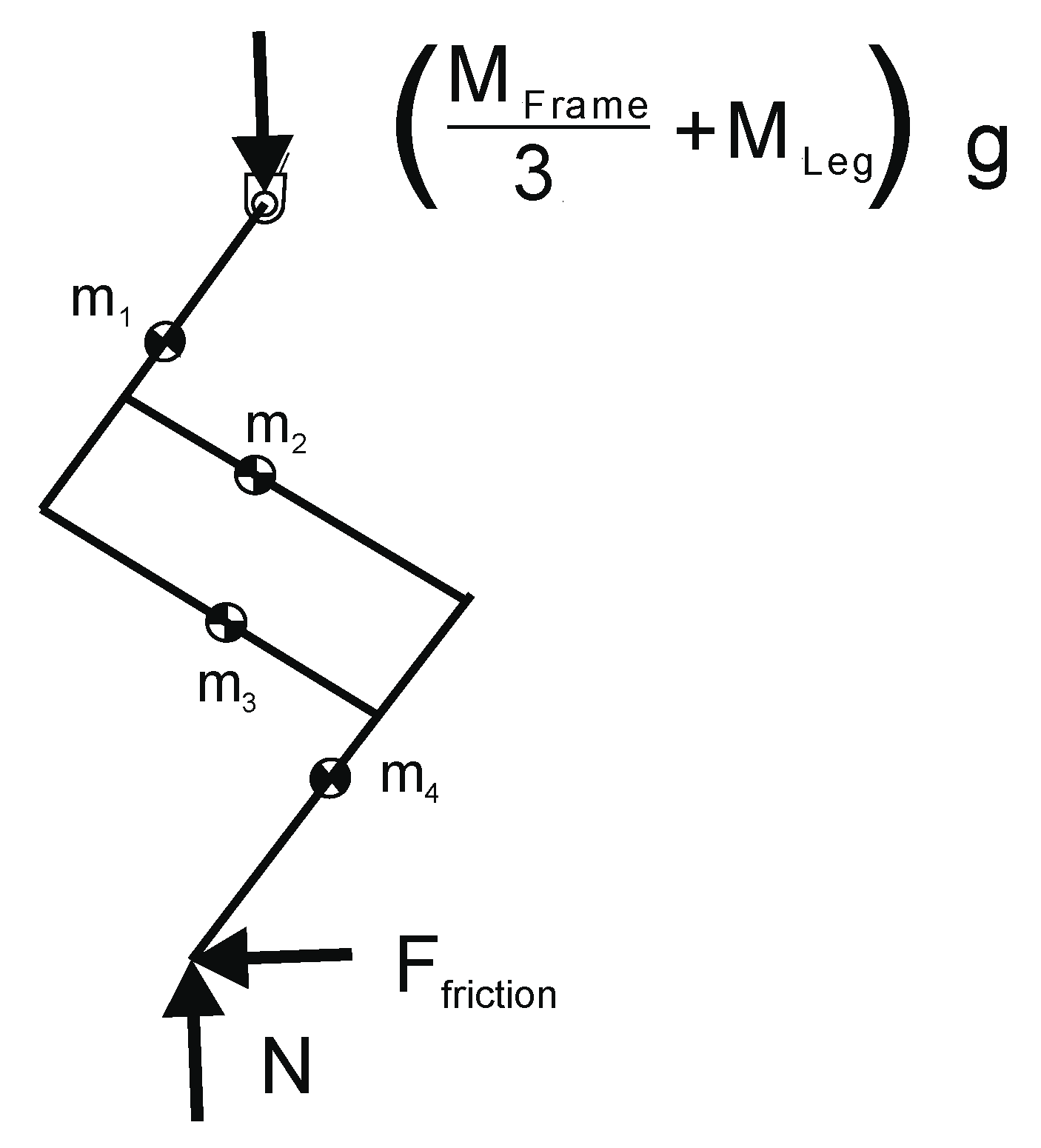
The forces N and F
Friction are present in the model of one leg, as shown in
Figure 5, and were evaluated according to Equations (12) and (13), as follows:
where N is the constraint reaction deriving from contact with the ground,
is the mass of the frame of the entire robot,
is the weight of the single leg, g is the gravitational acceleration constant (9.81 m/s
2),
is the force of friction, and K
d is the dynamic friction coefficient considering a contact of the rubber-cement type and with a value equal to 0.5. One should note that Equation (12) refers to the case of three legs in contact with the ground while only a single leg is lifted up. Accordingly, the mass of the frame,
, is distributed equally among three legs, and the mass of the single lifted leg,
, sums up to compute the total normal force, N, acting on each leg in contact with the ground.
The weight force of the frame weighs on the movement of the paw only when it appears to be in contact with the ground; therefore, in reference to the trajectory traced in
Figure 8, a time of contact with the ground equal to 0.4 s was estimated. From these considerations, we can build a dynamic model based on Lagrange’s equations. After calculating the potential and kinetic energy of the system, as shown in
Figure 6a,b the Lagrangian function is calculated according to Equations (12) and (13).
where
and
, respectively, represent the total and potential kinetic energy of the entire system in
Figure 6. Lagrange’s equations were obtained starting from Equation (14), as follows:
where
is the resisting torque due to the constraint reaction, N, and
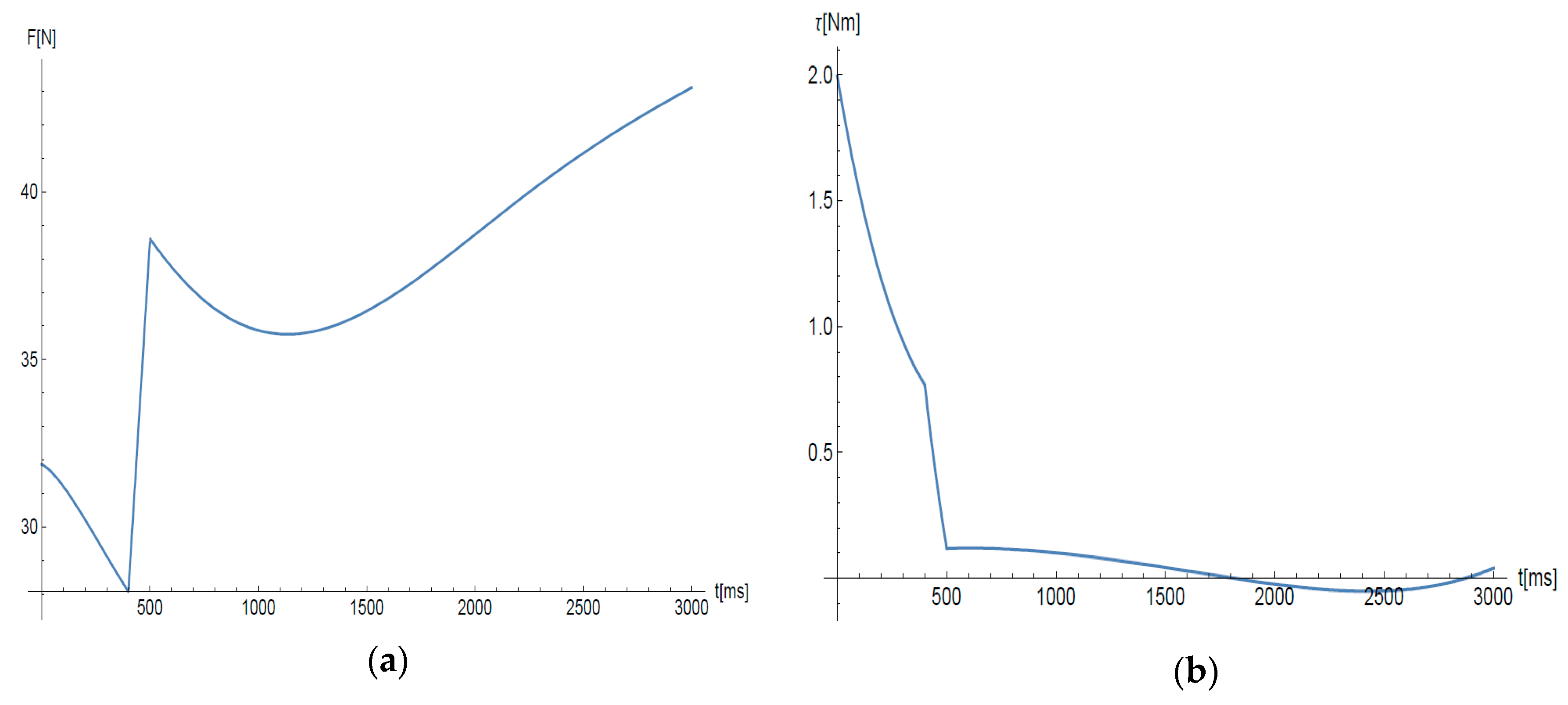
is the resisting torque generated by friction during the time of contact. Equations (15) and (16) were solved through the Wolfram Mathematica software, providing the torque and actuation force results needed to follow the trajectory in
Figure 8.
As can be seen from
Figure 9b, the torque to be applied is maximum at the time interval during which the paw touches the ground. Subsequently, there is a drastic decay of the torque values, due to a short transient during which the paw detaches from the ground. This is justified by the fact that the torque required to rotate the paw in the air must essentially contrast only its own weight. The transient duration was defined from practical viewpoint, with a very small value, equal to 0.1 s. Furthermore, a linear trend of the forces was assumed during the transient phase. As far as the tension of the rope is concerned, it can be noted (in
Figure 9a) that the constraint reaction contributes positively to the lifting of the leg during contact with the ground. Thus, this is decreasing the force necessary to lift it.
5. Hardware Selection and Prototyping
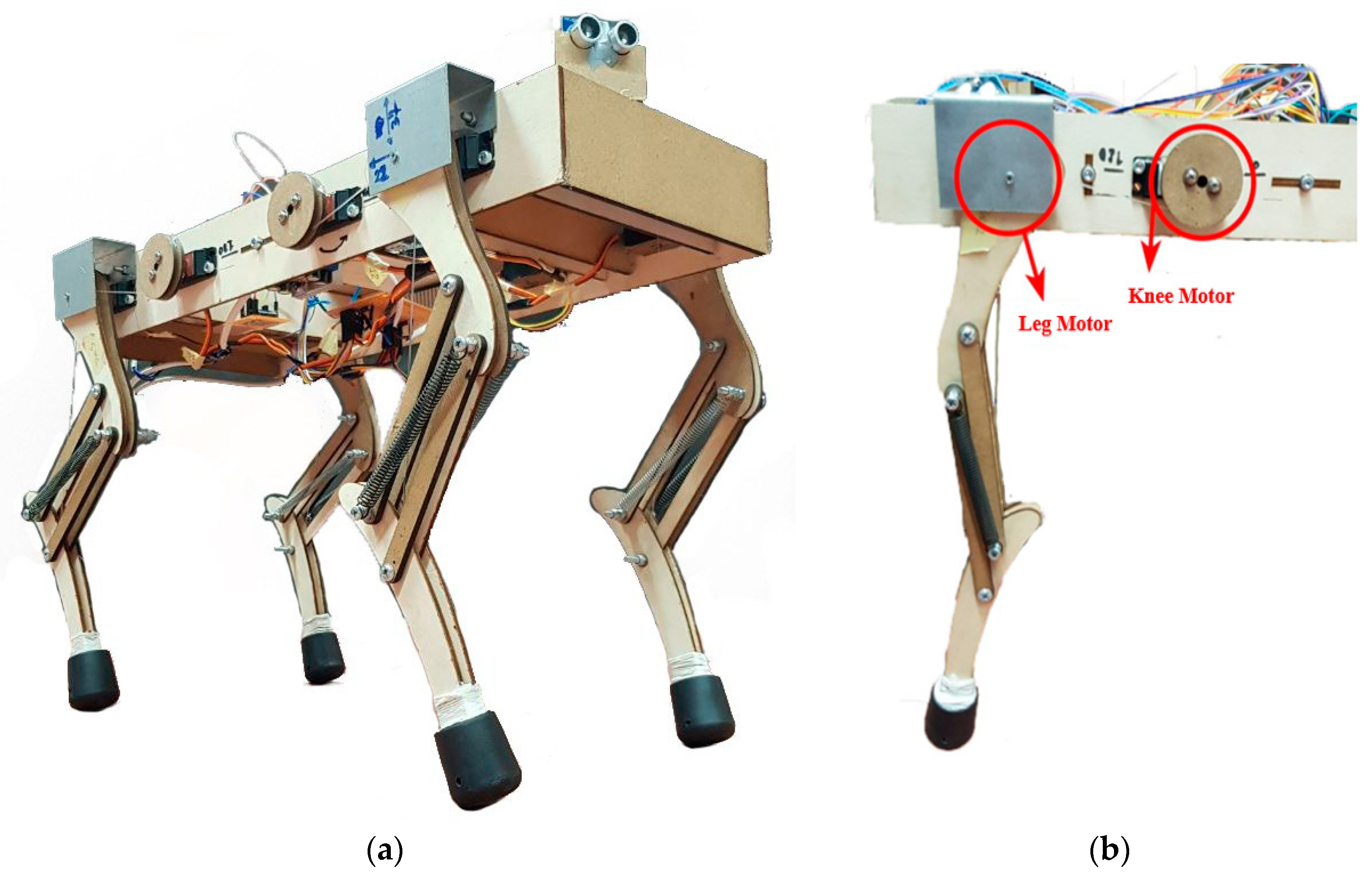
Eight motors are needed to actuate the robot, i.e., two on each leg. One actuates hip movement, and the other one actuates knee movement, as detailed in
Figure 10.
In this case, it is necessary to precisely control the position of the motors. This is achieved by using commercial servo motors (
Figure 10b). They allow us to control the angular position in a range between 0° and 180°, in a close-loop control, including an absolute encoder. Moreover, they are easily programmable with an Arduino board. The choice of motors was made starting from the results obtained in
Section 4, with the results of the inverse dynamics in
Figure 9a,b. The maximum actuation torque values of 2 Nm were detected for the leg motor, while the maximum force required to move the rope is about 45 N. Since the radius of the pulley is 2 cm, the maximum torque that the motors must exert to rotate the pulley will be approximately 0.9 Nm. Eight identical motors were selected, to simplify the control architecture. A JX Servo PDI-HV5932MG [
15] was selected with a 6.0 V power supply. In this case, the servomotor is delivering a torque of 2.5 Nm, which is higher than the maximum required peak torque, as reported in
Figure 9b.
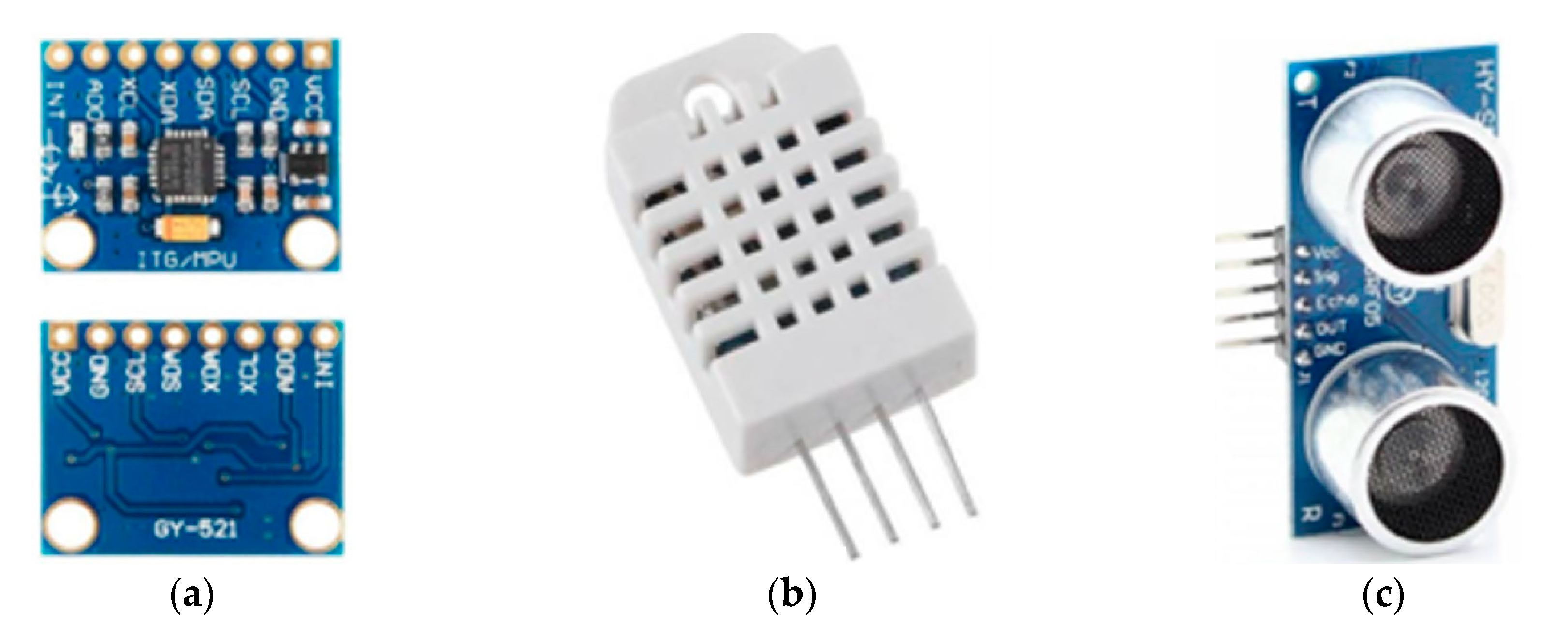
The robot is equipped with several sensors allowing the acquisition of data relating to both the robot external and internal environment. There is an IMU (inertial measurement unit) sensor providing accelerometers and gyroscopes, which allow monitoring of the dynamics of a moving robot body. The chosen IMU sensor is the GY-521 MPU-6050 (
Figure 11a). The InvenSense GY-521 MPU-6050 sensor [
16] contains, in a single integration, a three-axis MEMS accelerometer and a three-axis MEMS gyroscope. Its operation is very accurate, as based on a 16-bit analog/digital converter for each channel. As a result, it manages to simultaneously capture the values of the X, Y, and Z axes.
The measurement of temperature and humidity of the external environment is carried out via a DHT22 sensor (
Figure 11b). This sensor allows us to detect the relative humidity and temperature of an environment and to transmit it digitally through a single wire (in addition to the two necessaries for power supply) to a microcontroller [
17]. The humidity sensor is of the capacitive type. It uses a maximum of 2.5 mA in work and allows us to acquire a maximum of one sample each 2 s. The humidity measurement varies from 0 to 100%, with a typical accuracy of ±2%. As for the temperature, the DHT22 has a measuring range between −40 and + 80 °C, with an accuracy of 0.5 °C, by using a DS18B20 sensor integrated inside the robot body. To detect the presence of objects in the immediate vicinity, an ultrasound SRF05 sensor is used (
Figure 11c). This sensor is equipped with a microcontroller that provides all the processing functions. It is enough to send an impulse and read the return echo, to establish the distance of the obstacle or object in front. It can identify even small obstacles and objects from a minimum distance of 3 cm up to 3 m [
18]. Like all ultrasonic sensors, it is insensitive to light, so it can also be used outdoors. It is also ideal for applications requiring greater precision or range. The sensitive workspace of this sensor is quite wide, and it can be optimized by adjusting its sensitivity threshold.
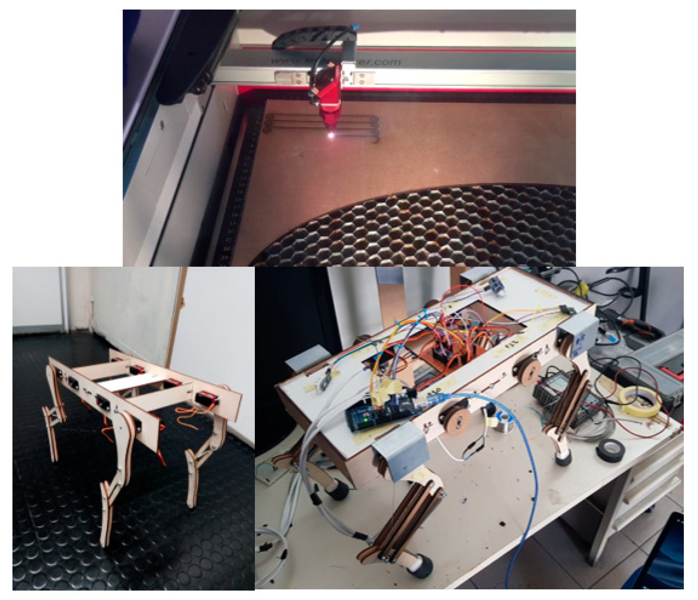
With reference to
Figure 12, it can be observed that the proof-of-concept prototype was made by using low-cost off-the-shelf components. The structure is mostly made of wood; the components were laser-cut and assembled through bolts and gluing. Steel parts were also made to support the load on the leg motors, while the rope that moves the knee is a nylon fishing line.
After generating the complete CAD model, the 2D files were exported for cutting, and the pieces were assembled, considering the moving parts and the games necessary for moving the links. The springs were chosen based on the torque delivered by the servo motors and based on the weight of the robot pitch; they aim at returning the robot to an upright configuration.
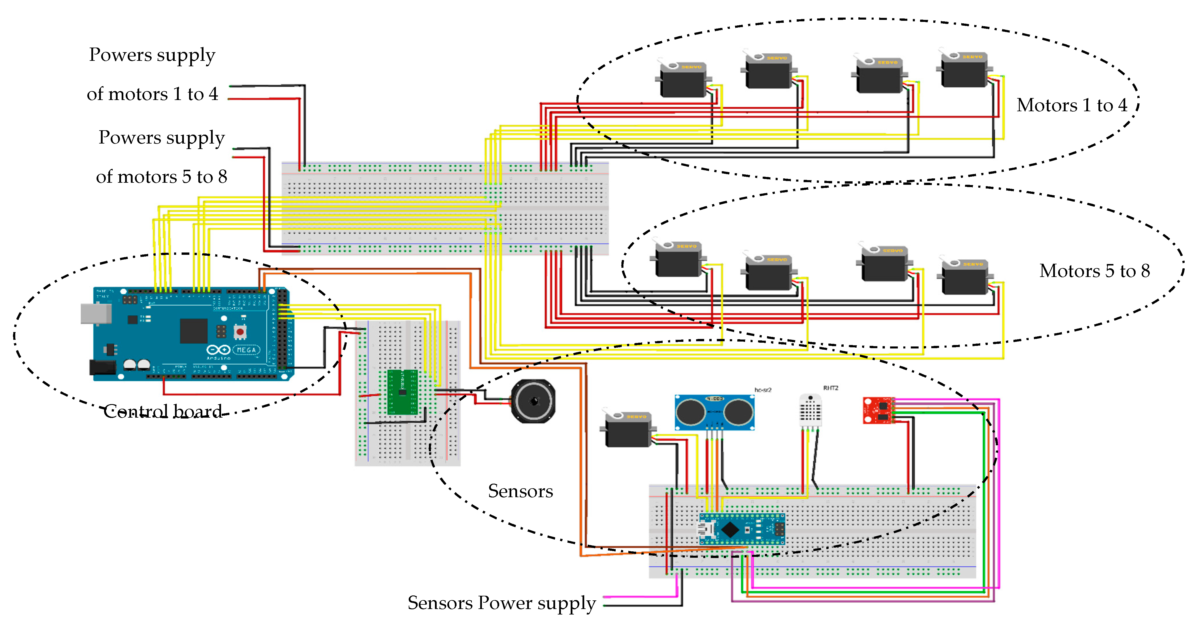
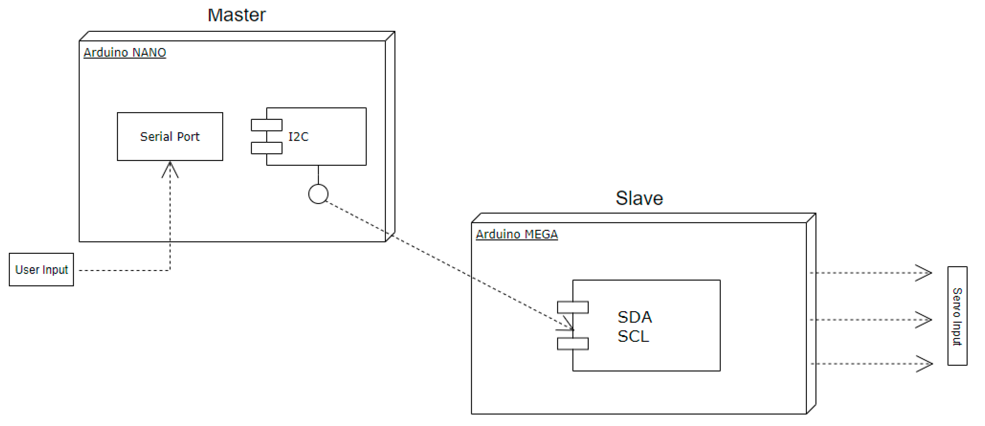
Figure 13 outlines the electrical wiring of the prototype with a 12 V input power supply. Voltage regulators are used to provide 6 V as input power for the servomotors. Voltage regulators were doubled, to guarantee a maximum 15 A output current. This value was calculated by considering that each servomotor must be powered at 6V −5A (30 W), to provide the required torque (2.5 Nm). The sensors, instead, require a 5 V power supply, which is always supplied by using a stabilized voltage regulator. An Arduino MEGA 2560 R3 controller is also powered through the same regulator. As shown in
Figure 13, two Arduino controllers were used: an Arduino MEGA 2560 R3 in combination with an Arduino NANO. Communication between the two Arduinos was achieved via I2C communication. The Arduino Nano has the master role and communicates with a PC, serially, sending the sensor data and receiving input commands by a user, from a specifically developed graphic user-interface. The Arduino NANO transmits the commands to the Arduino MEGA, which begins the calculation for the gaits. The master-and-slave Arduinos are connected via two SDA (serial data)–SCL (serial clock) standard communication cables. Only the pins with PWM (pulse-width modulation) outputs are connected to the Arduino MEGA for controlling the servomotors, while the Arduino NANO is connected via I2C not only to the Arduino MEGA but also with the 3-axis accelerometer (IMU), the radar sensor, and the temperature and humidity sensor.
6. Main Programming Architecture
The control and sensors’ feedback architecture is entirely managed by the Arduino NANO controller, as shown in
Figure 14. The program compiled and loaded on the sensor controller acts as the master for the whole system. In fact, it simulates multi-thread processes that allow it to be able to quickly acquire information from the sensors without ever stopping (as in the case of a single process). The reading of the outputs of all the peripherals is carried out simultaneously, and all the data are subsequently sent to the various viewers. The
delay() function can be avoided through a technique based on the system clock, which slows down the data transmission speed. This technique therefore simulates a parallel execution of all reading processes. The process begins with the creation of a class that is used for the creation of objects in the programming. It includes attributes and methods that will be shared by all objects created (instances), starting with the class. The objects that can be instantiated by the class are events (I2C reading from the sensors, reading, and writing on the serial port). The attributes related to the objects of the class define the time that elapses between the execution of an action and its subsequent repetition. This time is evaluated by counting the milliseconds, starting from the system activation time, using the
millis() function. The logic of the object ensures that the system does not stop until a predetermined time interval is exceeded; once exceeded, the process linked to the object itself is reactivated. In this case, the I2C communication requires the master to take the action command from the serial port that the user wants the robot to do and send it back to the motor controller, in the form of Byte.
As shown in
Figure 14, the servomotors are controlled through the Arduino MEGA 2560 R3 controller. The
#servo library was used to control the movement of the servomotors, which automatically manages PWM communication. To facilitate programming and control logic, a special class was created that manages each leg and all legs of the robot.
7. Preliminary Testing Results
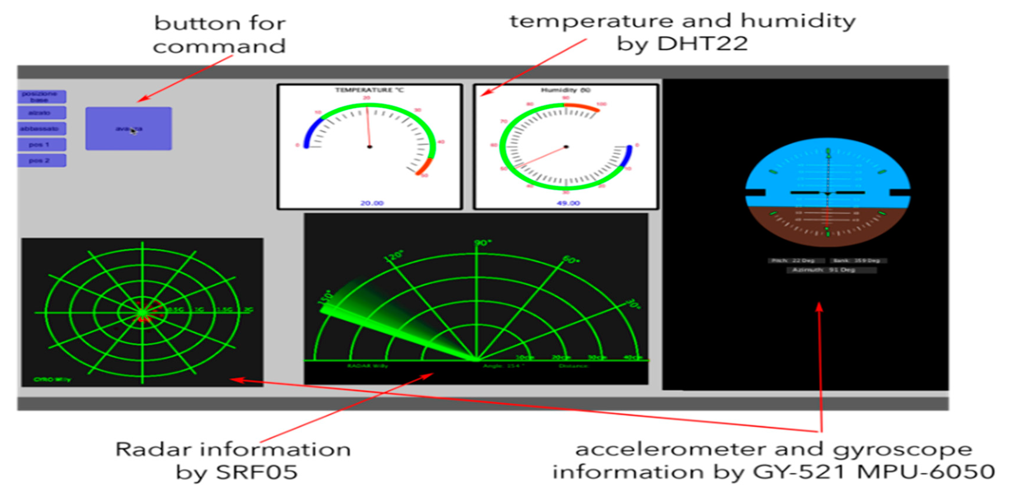
A dedicated user interface was developed in Java programming language, as shown in
Figure 15, with the aim of making the output signal from the sensors as user-friendly as possible. This allowed us to conduct a series of preliminary tests and a preliminary comparison of the robot’s performance. For each test, the robot covered a total distance of about three meters, demonstrating the synchronization speed, this led to defining an optimal walking speed that allowed us to obtain maximum walking stability.
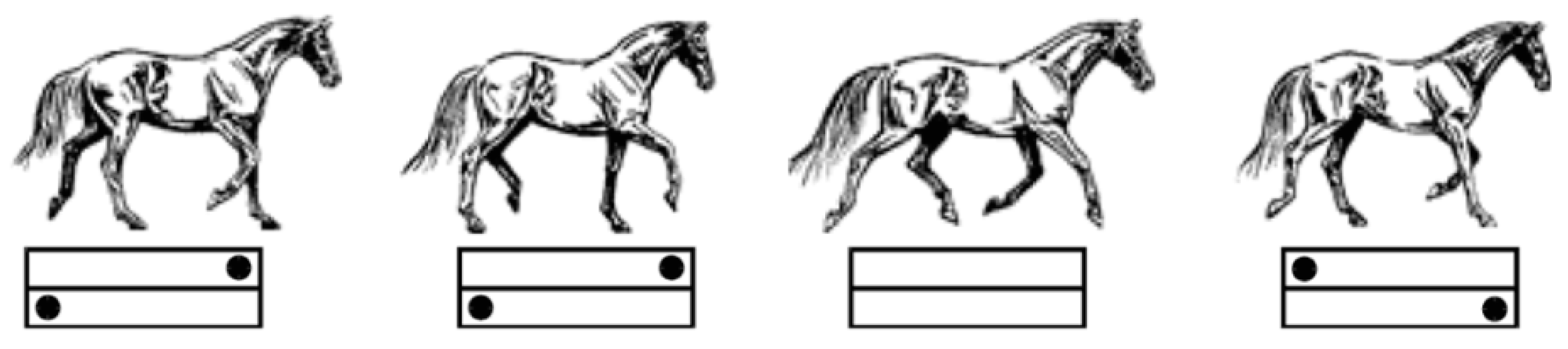
A specific motion strategy was implemented proposed in the scheme of
Figure 16 with a sequence of diagonally opposite legs can rest or move alternatively. The gait sequence starts from the right rear and front left and then vice versa, as also discussed in References [
14,
19].
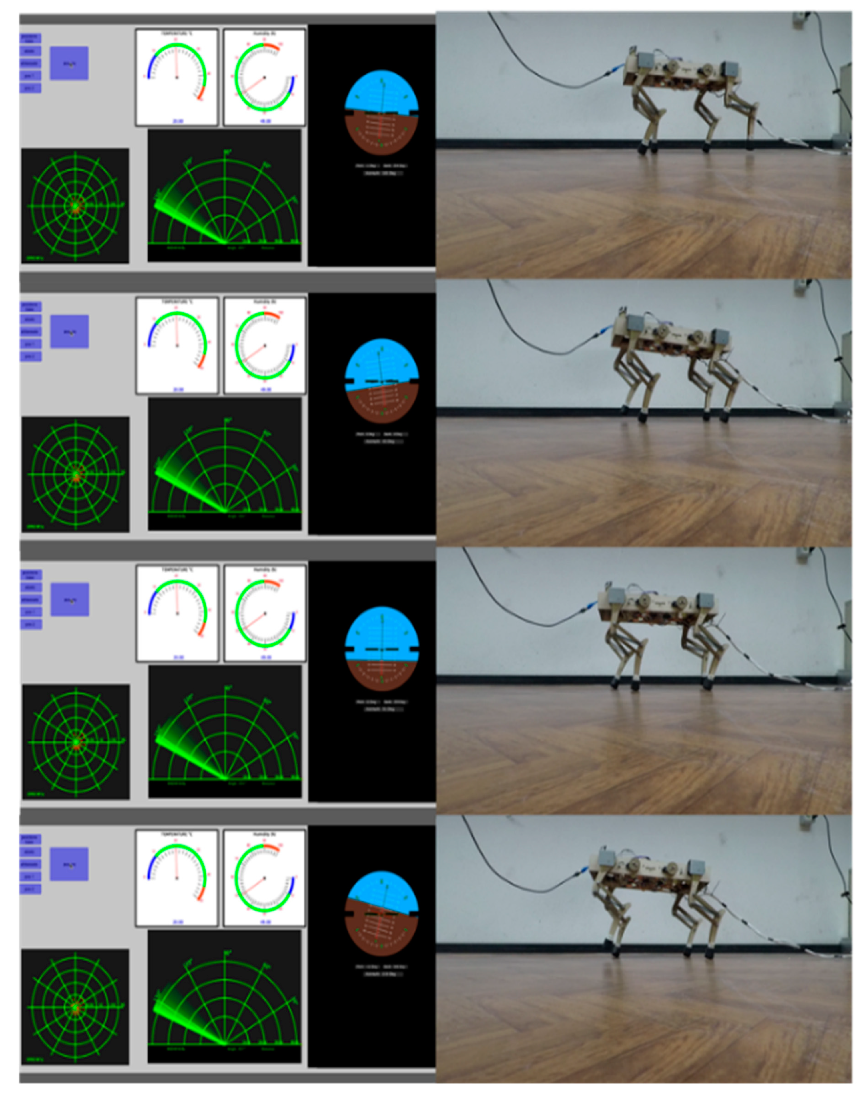
Figure 17 reports some snapshot frames taken from videos of the experiments. Through the frames, one can clearly see that the synchronization movements of the legs are allowing the robot to walk, for instance, at very low speed. In such a case, the center of gravity must always be within the stability triangle area described by connecting the three support points. When increasing the speed, we achieve a dynamic motion by using a trot gait strategy. In this case, the support points shift from three to two, and a dynamic equilibrium needs to be achieved by considering the inertia of the robot body.
Figure 17 confirms that the desired dynamic gait was successfully achieved.
The reported experiments have preliminarily demonstrated the proper operation of the prototype in achieving complex dynamic gaits. They also demonstrate the effectiveness of the attached very challenging topic for successfully engaging students towards learning very complex theoretical, numerical, and practical skills. Further studies will be carried out in future, to explore the potential use of the built prototype for multiple applications including exploration, patrolling, surveillance of unstructured environments, as proposed, for example, in References [
20,
21,
22].
8. Conclusions
This paper outlines the conceptualization, design, and proof-of-concept manufacturing of a low-cost and user-friendly four-legged robot that is fulfilled within a proposed general design procedure. Each design phase is discussed for identifying the main features and key points as part of a multidisciplinary approach. Namely, the proposed procedure includes (but it is not limited to) mechanism design, kinematic, and dynamic modeling/simulation, to inform a proper design procedure and to achieve a proper selection and adaptation of off-the-shelf components. The proposed design procedure results in developing a specific leg design topology with 2-dofs kinematic architecture for each leg, in combination with a crank and rope driving mechanism and a balancing spring. A prototype was built based on the proposed procedure, and it was integrated with all the mechatronic components, including control and sensory hardware. A specific user-interface and software was also developed based on a dedicated master–slave Arduino architecture. An experimental validation was successfully reported to demonstrate the fulfilment of the desired key performances in terms of static and dynamic gaits, as well as in terms of real-time collection of environment data. These successful results were obtained by a team of masters’ students within a teamwork project. This also demonstrates the effectiveness of the proposed challenging multidisciplinary mechatronic design task as an effective means for non-conventional learning of multiple complex topics. In particular, it demonstrates that the proposed interesting and very challenging topic can successfully engage students towards learning very complex theoretical, numerical, and practical skills.

 ,
, 


