1. Introduction
In recent years, medical devices for motion assistance have become of great interest in research due to their wide range of applications, ranging from rehabilitation therapies to motion exercises for patients in recovering, from exercising for elderly people to motion augmentation for healthy people for better motion capabilities [
1,
2,
3,
4,
5].
Some of the proposed solutions provide help for specific articulations, while others provide full limb support. Different mechanism purposes result in different devices or exoskeletons with a variety of performances.
Each human articulation is defined by specific anatomy and motion characteristics; therefore, the design of a medical device is directly linked to the requirements of the specific articulation (e.g., [
6]). Among them, elbow articulation seems not to be properly addressed and in literature few assisting devices can be found [
7,
8,
9,
10,
11]. One of the proposed devices is CADEL (CAble Driven device for Elbow assistance), whose design has been conceived specifically to provide a specific solution for elbow articulation with wearable user-oriented features [
12,
13].
Cable-driven systems have attracted great interest [
14], even with parallel architectures, as documented for example in conferences like [
15,
16], in special issues [
17], and in special sessions in Robotics conferences [
18,
19]. In particular, parallel manipulators with cable architectures are sources of novel designs for medical service applications, like, for example, Refs. [
20,
21].
Alternatives to cables have been shown during the years [
22,
23]. In particular, Ref. [
22] shows a soft material that could be used as soft actuator, and Ref. [
23] describes a pneumatic actuator that can be activated with a heat source, so without the need for an external compressor. The applications for the aforementioned technologies, even if promising, have been limited to the research field. Their specifications, in terms of power consumption and movement times, are not suitable for an easy-to-use, portable device, like CADEL.
In terms of existing solutions, many devices have been proposed over the years [
1,
24]. However, most of the time, the proposed designs are related to clinical usage and the devices are not easy to move. The aim of CADEL is to create a device that is easy to carry and can be easy to be used in a home environment for home exercises.
During the last few years, lab experiences with CADEL prototype at LARM 2 in Rome Tor Vergata were carried out to evaluate the feasibility of the solution but also to identify any efficiency issues for practical usage in home user-oriented applications [
25]. Home user-oriented applications are of great importance due to the long and repetitive rehabilitative sessions the patients have to perform [
26], which usually require the presence of a physiotherapist in dedicated structures. Moreover, after specific trauma, numerous research shows how it is important to constantly perform specific exercises during the following months [
27,
28,
29,
30].
Starting from the lab experiences with the CADEL prototype, an improved CADEL mechanism design has been developed [
31,
32]. In this paper, a refinement of this mechanism design is presented, in which practical production aspects have been considered. The final design has been tested both with numerical simulations and experimental tests on a healthy subject, also for characterizing the feasibility of the proposed improvements and new solution.
2. Elbow Motion Requirements
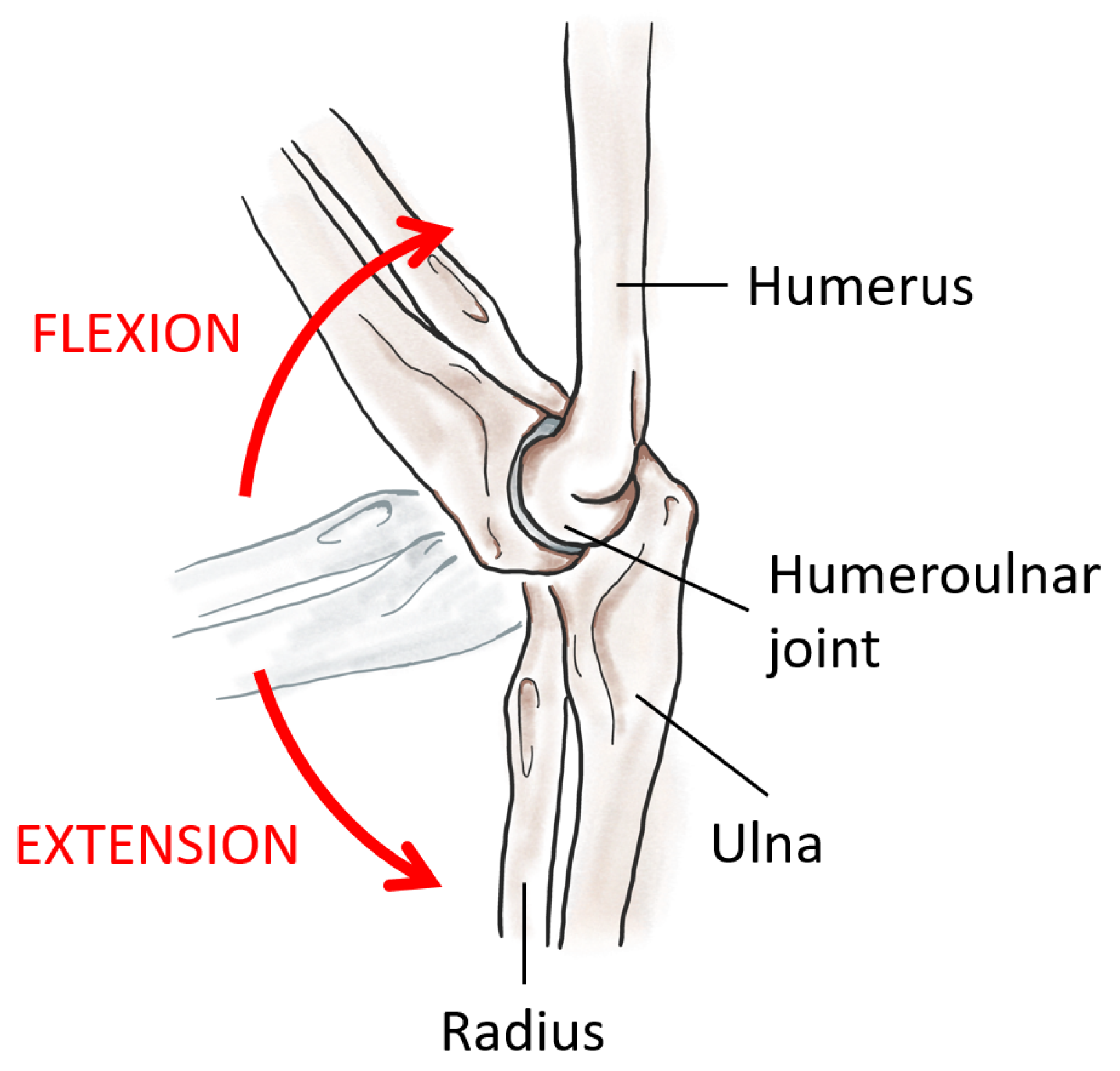
The elbow anatomy is characterized by three joints which connect the arm and forearm bones (humerus, radius, and ulna) (
Figure 1). These three joints allow the two rotations of the forearm: the flexion–extension and the rotation around the forearm’s axis.
Among these two rotations, the predominant is the flexion–extension. Flexion and extension movements are provided by antagonist muscles, and therefore each movement can be used to exercise different muscle fibers. These movements can be described as a rotation around the elbow axis, perpendicular to the sagittal plane that is formed by the axes of the arm and forearm. The overall range of motion is usually around
, starting from the full extension (forearm aligned with the arm) [
34]. For a
m tall man, mean values for the lengths of arm and forearm are
mm and
mm, respectively [
35].
The maximum range of motion allowed by the device depends not only on human anatomic limbs (as aforementioned), but also on shape, size, and position of the rings. In particular, in the full extension (forearm aligned with the arm), the angle is equal to , while, in the full flexion, it is . The latter value is due to the interference between upper and lower ring platforms that prevent the complete flexion of the elbow.
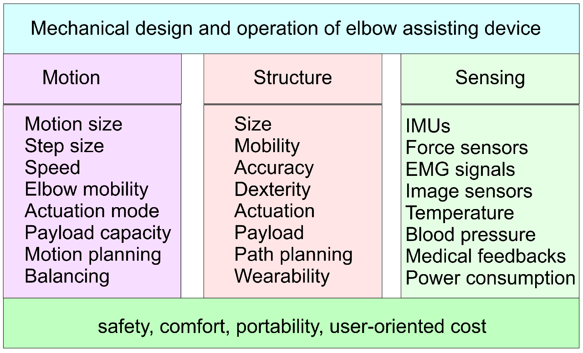
Figure 2 summarizes main aspects that have been considered in the conception and design of the structure and the operation of the CADEL device with specific attention and rethinking in the improvements for the CADEL.3 solutions.
In particular, considering the motion assistance purpose, first attention is paid to the sizes of motion capability in terms of an identification of the range and resolution of the motion to be assisted. This also includes an evaluation of speed both in healthy users and in exercising patients as related to the elbow and whole arm capability. The quality and quantity of expected assisted motion will give an indication of the actuation features in terms of size and mode that can also be constrained from the payload coming from the active (no reactive elbow) or passive (full power of the arm) mode, or from additional loads for exercising/training purposes. The assisted motion can be planned with desirable timelines and motion characteristics with a suitable path planning of the driving cables taking into account the above considerations and the next ones on the other aspects which can affect or be required to have a properly assisted elbow motion. Balancing is a feature which can be understood not only as from dynamics point of view for having properly regulated and minimized the forces on the cables and arm, but even in considering a synergy of the action coming from the arm, with awareness or not from the user, and the feedback from the sensing equipment for device regulation and medical monitoring. Consequently, the structure features can be considered from requirements and peculiarities in the general but specific application in terms of the size and mobility of all the components of the device. This will require achieving a mechanical design of the parts with proper characteristics that are calibrated for human arms and their elbows. One key aspect in the design requirements can be considered the wearability of the device in the sense that it can be fairly easily worn on a user arm, even without help, and with a final comfort even during the device operation. This will require carefully considering the anatomic characteristics for the fixture of the ring platform on the arm and the cable handling, mainly during initial wear.
The operation and the efficiency of CADEL device can also be understood from sensing features to regulate the motion and action of the device and to monitor and evaluate its efficiency in the response of the elbow users. Thus, basic sensors are needed to regulate the device, such as IMU (Inertial Measurement Unit) for motion control and force sensors for cable tension control. Power consumption can be considered a practical aspect to limit both the energy flowing near the arm and to minimize the overall design. In addition, medical/clinic sensors are not only used to track the effect of the assisted motion on the anatomy of a patient, but they can even be used to better tune the assisted motion with respect to the status and response of the patient. Thus, sensors such as for local temperature and arm blood pressure can be a very promising complement to EMG sensors to detect the reaction and activation of the tissues and muscles serving on elbows. Medical feedback may include other sensors as requested by a specific patient and specific motion assistance as asked by medical operators supervising the device operation.
For all the above aspects, the main requirements for a successful design and improvement of the CADEL device can be well recognized in safety, comfort, portability, and user-oriented cost. Safety is a crucial point for any medical device and in the CADEL solution may require some more attention, not only for the direct contact of the platforms on the arm body, but also for the presence of tensioned cables near the arm body yet. Safety must be considered also against the device itself not only for an efficient operation but ultimately for patient satisfaction. Comfort is an issue which can decide the acceptance or not of a medical device, and must be considered at several levels in healthy and unhealthy users. Portability can be considered a key issue since the specific application for elbow motion assistance is thought for user anatomy in different environments, but mainly home. Finally, the cost is a final index which decides the acceptance and usage of any product, and particularly of medical devices when compared with normal assistance by an operator.
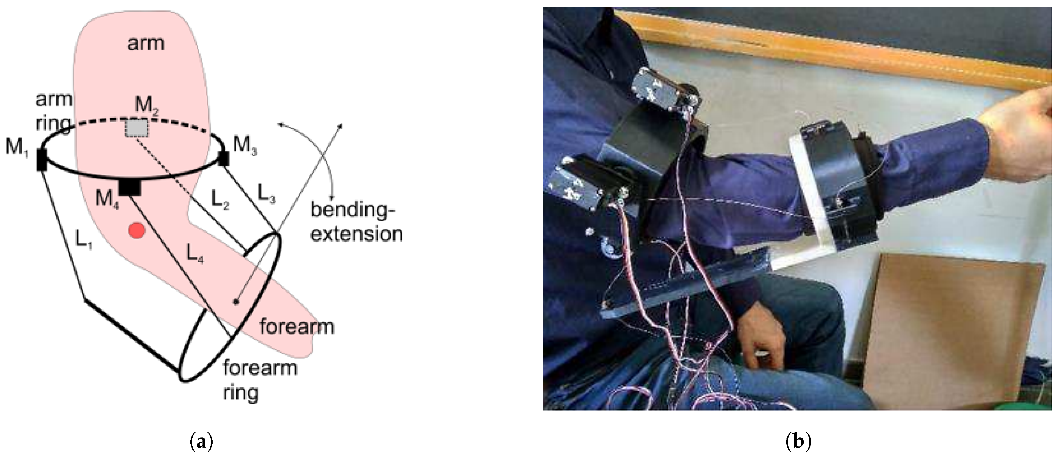
In
Figure 3, the original design of CADEL device is presented with a conceptual scheme in
Figure 3a and with a lab testing configuration in
Figure 3b. In particular, referring to
Figure 3a, the ring arm, which is worn on the arm body, is characterized by the four servomotors
actuating the cables
which are operated as pairs with antagonism mode (one pulls and the other release, and vice versa). Two cables in a pair (
and
) are used for bending/extension forearm motion, while at the same time the other two (
and
) are actuated quasi-statically to keep the arm motion in its sagittal plane. Otherwise, these two last cables can be used to assist the rotation motion of the forearm completing a wrist rotation. Alternatively, they can be neglected and even not included in the design and operation of CADEL if the above motion assistance is not required. Anyway, in each motion, both pairs have a cable that drives the motion (“master-cable”) and a cable that follows the consequent movement (“slave-cable”). In
Figure 3b, the wearability of the first prototype at LARM 2 in Rome is shown with its features but with critical aspects of bulky design, uneasy wearability, and not completely satisfactory efficient operation.
With its improved design, CADEL.3 has improved mostly the flexion–extension assistance of the original prototype, so, in the following sections, the paper is focused on this particular movement. The desired maximum range of motion has been considered from (full extension) to (maximum passive flexion).
3. The Improved Mechanism Design
CADEL is a device that has been conceived to assist the movement of the elbow of a patient. As a result, it has specific requirements (
Figure 2): in terms of motion, since it must provide specific help in a specific range of motion and payload; in terms of structure, since it has to be compact and easy to wear; in terms of sensing, since it has to provide a bunch of parameters to the medical operators.
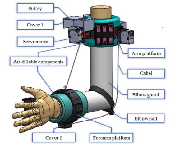
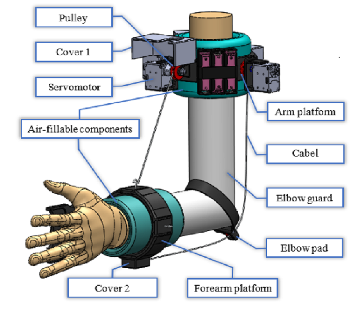
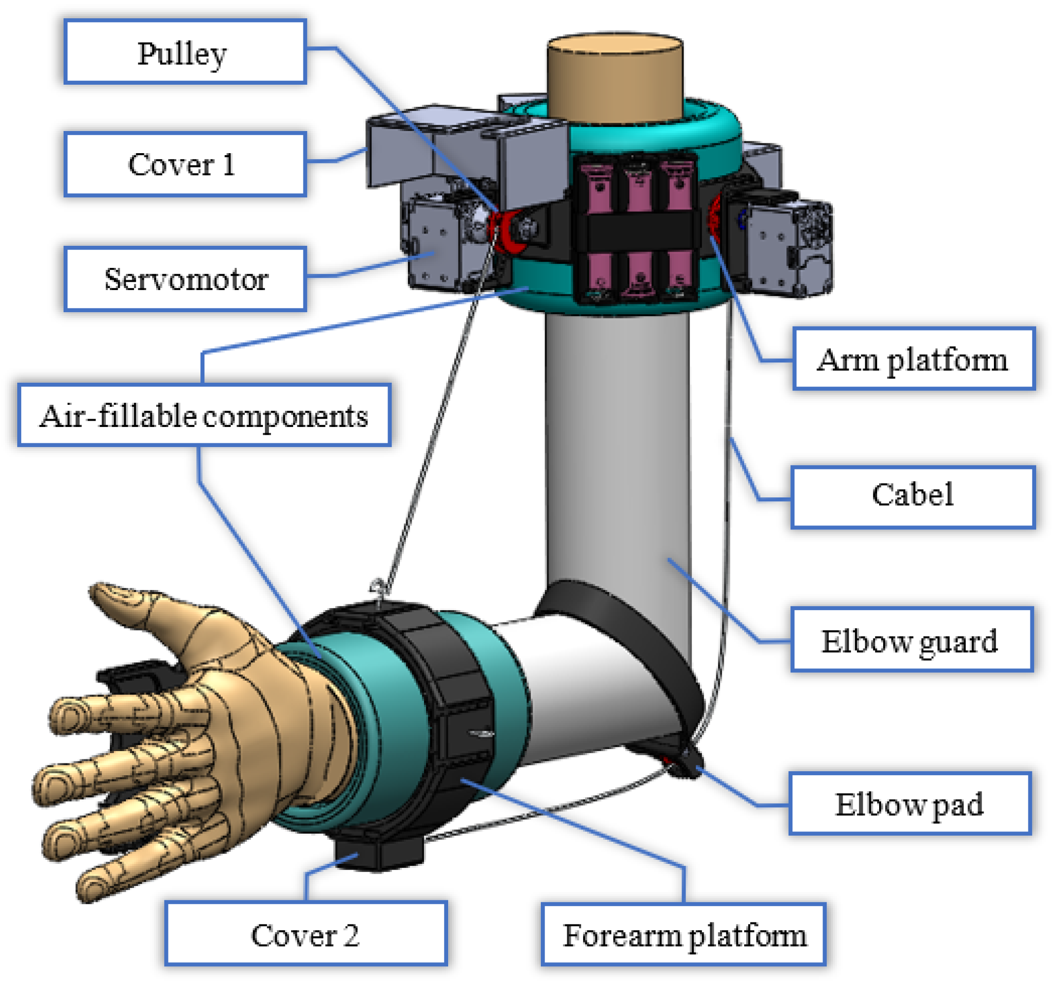
To fulfill all these requirements, the design of CADEL.3 device (
Figure 4) is made up of the following parts:
Arm platform and forearm platform, as two rigid bodies that are used to include all the moving parts (e.g., the motors);
Two air-fillable components that are used to easily fix the platforms to the limbs and to provide a good centering of the platforms around arm and forearm axes thanks to a homogeneous pressure applied by the air;
Four cables, as the driving elements for the motion assistance/guidance, two for each movement;
Four servomotors Dynamixel with associated pulleys, two for each pair of cable. The motion transmission is allowed by a crankshaft that is fitted to each motor to ensure the correct rotation;
An elbow guard that wraps around the arm and connects the two air-fillable components. This component is used to improve wearability with proper stable location of the platforms;
An elbow pad with a pulley to constrain cable passage around the elbow;
An Arduino board with an additional specific shield to control Dynamixel servomotors, both installed within a box;
Three Li-ion batteries and related current-tension stabilization system, which are on the arm platform.
In order to improve wearability, at first, the cables are winded up around the motor’s pulleys; once the device has been worn by using the air-fillable components, cables can be pulled and attached to the forearm platform through proper hooks. Nylon has been chosen as cable’s material since it can provide good elongation and low friction along with good tensile strength. As from previously reported simulations, the maximum front cable elongation is equal to mm at the maximum tension, while the rear cable reaches an elongation of mm under the same circumstances. Theoretical analysis demonstrates that these values can be neglected because cable elongation leads to an angular variation at an elbow joint less than , and it does not influence the average value reached by the device in the central part of the assisted movement.
The platforms have been equipped with two additional covers to protect device components. The first one (cover 1 in
Figure 4) is placed upon the front motor to protect both the device and the patient during the flexion movement. A hole on the cover has been included to allow cable passage. The second one (cover 2 in
Figure 4) is placed on the bottom part of the forearm platform and allows the patient to rest the forearm on a surface (e.g., a table) without the worry of harming the rear cable.
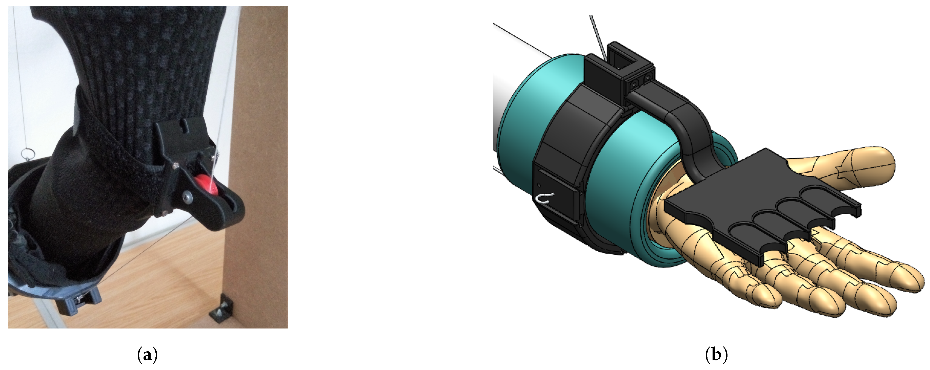
As for the pulley to be placed at the elbow to allow cable passage, a few solutions have been tested and considered. The final design in
Figure 5a uses a single pulley with a cable entry to protect the pulley from any contact with surfaces and to prevent the cable to unwrap from the pulley. In the proposed design, the connection between the pulley and the elbow guard is made up of Velcro to ensure both flexibility and stability.
In addition, for patients who are affected by flexor spasticity of the hand, a removable corrector tool as in
Figure 5b is introduced as an aid to straighten and open patient’s hand, aligning it along the forearm direction with the aim to ensure comfortable position during an exercise.
In summary, the design improvements in CADEL.3 with respect to the original CADEL device can be identified in:
reshaped design of platforms;
air-fillable components for stable and comfort wear;
elbow pad;
elbow guard;
on board batteries;
cover for exercise fixture;
flexor spasticity aid.
In addition, the principal elements that allow for reducing the weight of the structure are:
the optimization of the design, which includes a reduction of 15 mm in the length of the lower ring (improving at the same time stability and comfort during the motion) and the reconfiguration of the motor supports and pulleys for a better location on the upper ring;
the complete removal of the bottom part of the forearm platform (
Figure 3b) in favor of the elbow pad;
the correct realization of the customized components with 3D Printing Manufacturing with attention to printing parameters such as infill and profile structure.
These improvements result directly in an overall reduced volume, since more components are fixed to the arm platform, and improved wearability, since the cables can be fixed once the device is worn. In fact, there are no additional cables (e.g., from Arduino to the motors) that may tangle on the patient, and the device can be worn by pulling the elbow guard. In this way, it is easier for medical operators and for domestic use to carry around the device and to start the physical therapy with a more efficient operation.
The CADEL improvements proposed here have been designed and verified by an analysis procedure both from formulation and simulations whose results are reported in the next section.
4. Performance Analysis
Considering the above-mentioned design requirements, geometrical analyses have been performed through simulations. CADEL.3 dimensions have been chosen starting from the lengths that are listed [
35] for a
m tall man.
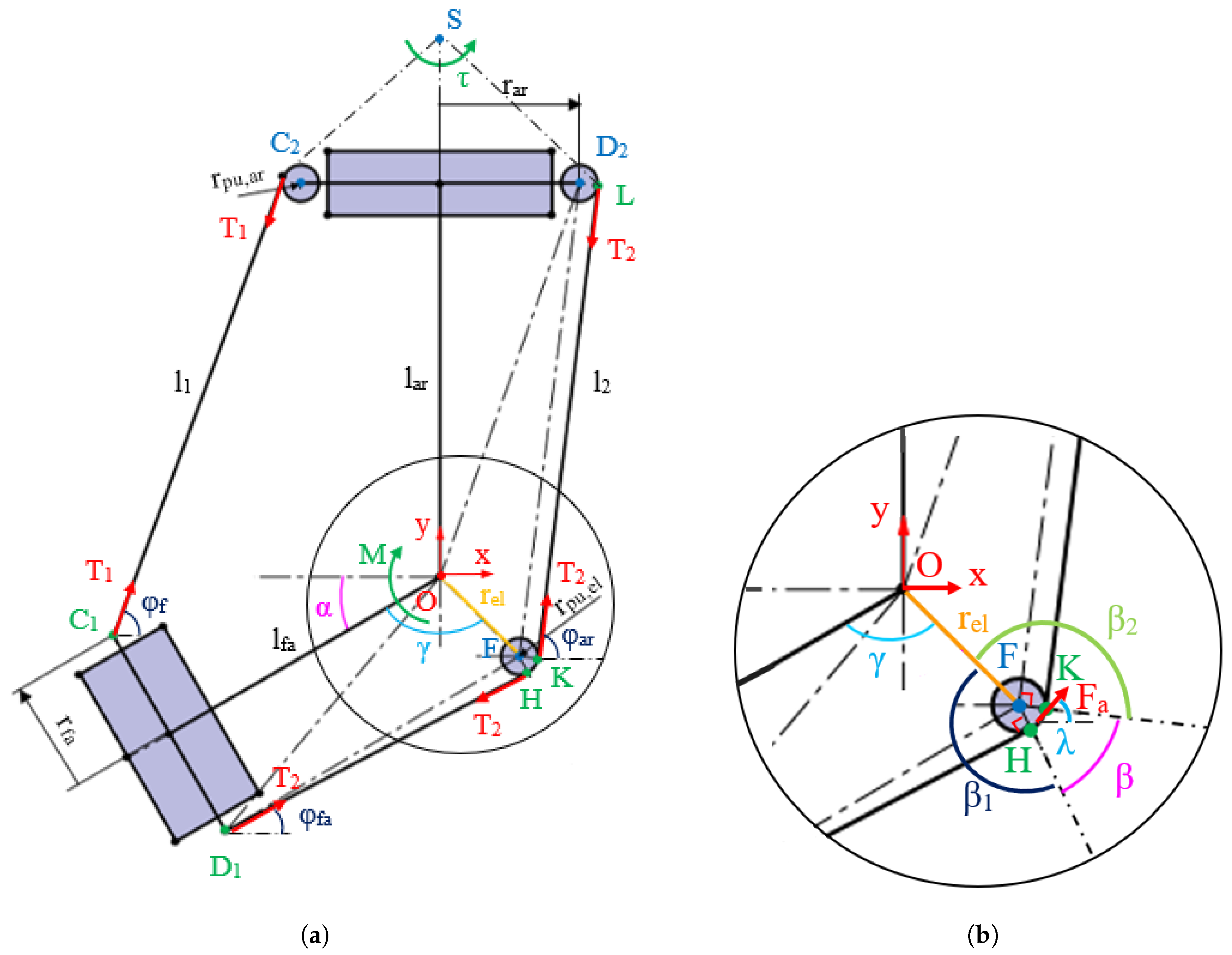
Figure 6 shows the kinematic scheme of CADEL.3. The flexion–extension movement is described by angle
;
is the length of the front cable,
is the length of rear cable;
and
are respectively
and
cable anchor points on the forearm platform, and
,
, and
F are the centers of the pulleys of the cable
, cable
and elbow, respectively.
The resulting device position on the upper limb and its dimensions are listed in
Table 1. These dimensions have been chosen so that the two platforms do not collide during the exercises and to place them in a position on the arm and forearm in order to avoid any slipping, i.e., close to the maximum point of enlargement of the arm muscles during the exercises.
In the simulation, the two platforms are perfectly fixed to the two parts of the limb respectively, and the arm is considered to be fixed. The origin frame for the simulation is fixed on the arm at the elbow joint. From
Figure 6, it is possible to compute front cable length as
where
Rear cable length
is equal to the sum of three segments given by
with
The coordinates of the reference points in
Figure 6 can be expressed as
Using scheme in
Figure 6b, it is possible to compute the value of the angle
as
where
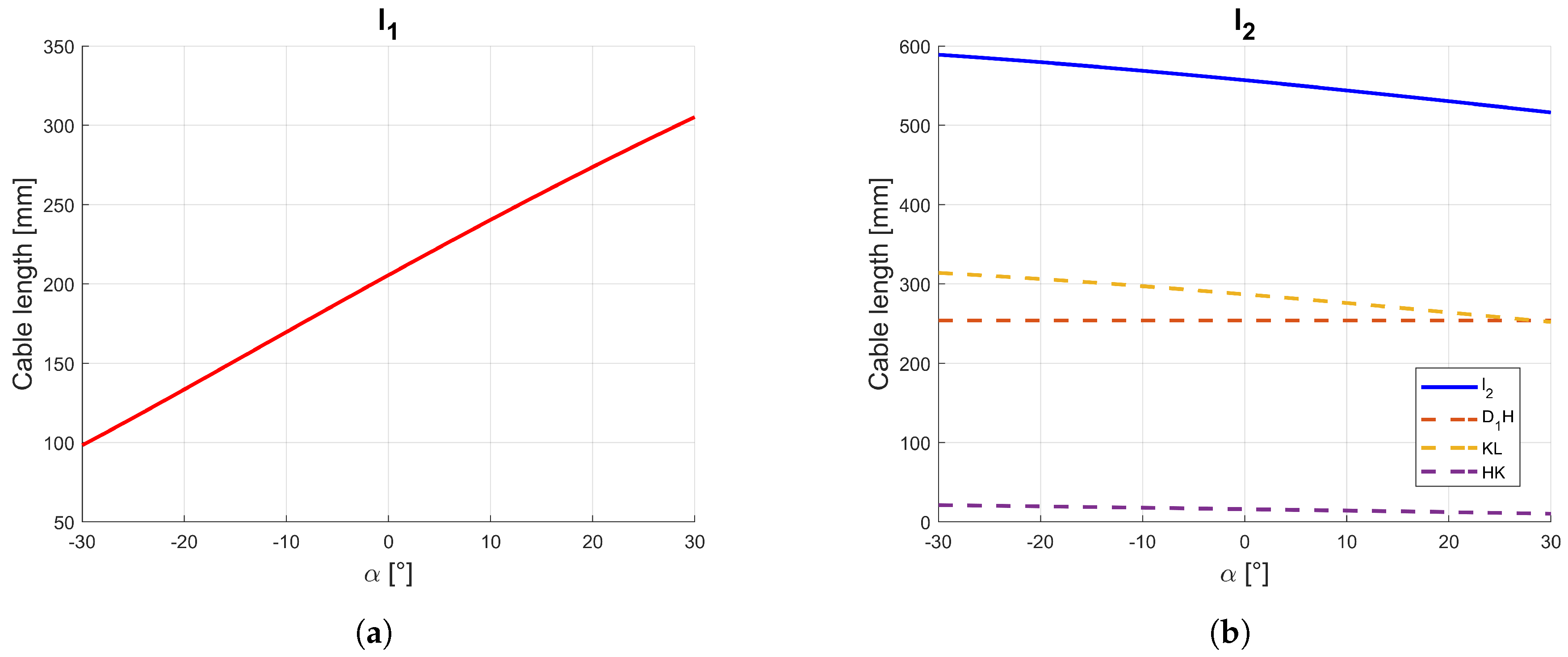
During the simulation of the extension motion, cables length variation can be evaluated by Equations (
1)–(
7) with results in
Figure 7, where both
and
cables present a near-linear trend which increases for
and decreases for
. In particular, referring to
cable,
presents a constant value of
mm (since the elbow pulley is fixed with the forearm) and
changes between
mm and
mm. The near-linear trend of cable’s lengths is useful since it gives a more fluid movement of the device with a convenient control law for the motors. Moreover, the small range of the
cable length that is wrapped on the elbow pad pulley ensures low friction and limited power consumption.
A static analysis has been performed by using the model in
Figure 6 with the forces and torques which are applied to the system as coming from the action of the servomotors. In order to simulate the resistant moment that can be exerted by a patient at the elbow, a moment of
Nm is applied to the elbow joint, while the tension of the “slave-cable” (posterior during flexion, anterior during extension) is assumed equal to 5 N in order to pull the cable and to prevent the cable from slipping out of the elbow pulley guide.
Then, referring to
Figure 6a, during an assisted motion it is possible to calculate master cable tensions as
with
e
as versors of forces
and
on the forearm, respectively,
z-axis versor, and
,
, and
angles that are formed by the cables with respect to the
x-axis (
Figure 6),
is the friction coefficient which is due to the action of rolling friction force
that is inclined by an angle
with respect to the horizontal, which is estimated as the average between
and
.
From
Figure 6b, angles
,
and
can be computed equal to
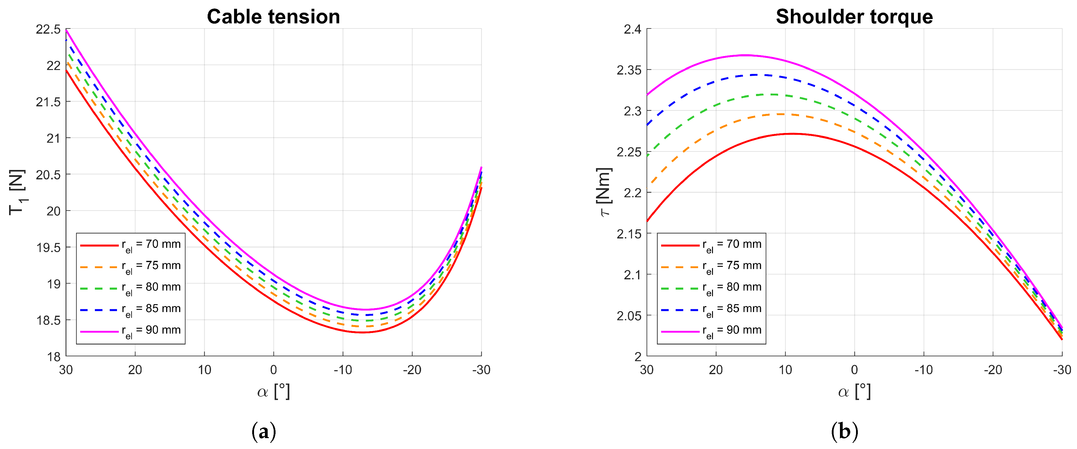
Simulation results from Equations (
8)–(
12) are reported in
Figure 8 with significant outcomes. To find the most efficient and patient-friendly trend for cable tension and shoulder torque, the distance of the elbow pad pulley from the elbow can be adjusted within 70 mm and 90 mm. The minimum value of the elbow radius represents the most favorable condition, since it ensures no contact of the posterior cable with the forearm platform or with the body limb during motion. As shown in
Figure 8a, however, even slight increases of
does not influence the overall behavior of the structure since peak tension of
is around 22 N with a minimum value of around
N, with a fluctuation due to
of about
N.
Thanks to the design configuration, using Equations (
8) and (
9), the motor torque
and motor power
of the servomotors can be calculated by
where
and
are the angular velocities of the motors that move the cables
and
respectively.
To test the impact of the device movement on a patient, the torque applied to the shoulder can be calculated as a result of all the forces shown in
Figure 6a. The shoulder is considered as a hinge that is placed
mm above the elbow [
35] and the resulting reacting torque
of the shoulder can be calculated as
where
is the distance between the shoulder hinge
S and the elbow,
and
are the vectors that connect the shoulder hinge to the points of application of the forces
and
on the arm platform, and
is the versor of
on the arm.
Simulation results are summarized in the plots in
Figure 8. in particular,
Figure 8b shows how
has a higher impact on shoulder torque
when the elbow is extended (±0.15 Nm) rather than when the elbow is flexed (±0.015 Nm). Those are actually low value variation since, even in the least favorable condition (elbow extended), changing
from 70 mm to 90 mm gives an increase of around
in shoulder torque only.
5. Prototype and Experimental Characterization
A prototype of CADEL.3 has been built with the proposed improvements at the Laboratory of Robotics of the Department of Industrial Engineering of the University of Padua. Whilst most of the components were selected as being available as commercial products, some parts such as the platforms, covers, and pulleys have been built by using a FDM (Fused deposition modeling) 3D printer.
The weight of the entire structure is of 10 N, so that it is possible to move around CADEL.3 with no excessive effort. Moreover, the retractable cables and the compactness of the platforms result in an overall compact device. Due to the fact that all the electronics and the sensors are placed on the arm platform, there are no additional cables which may annoy a patient during movement executions.
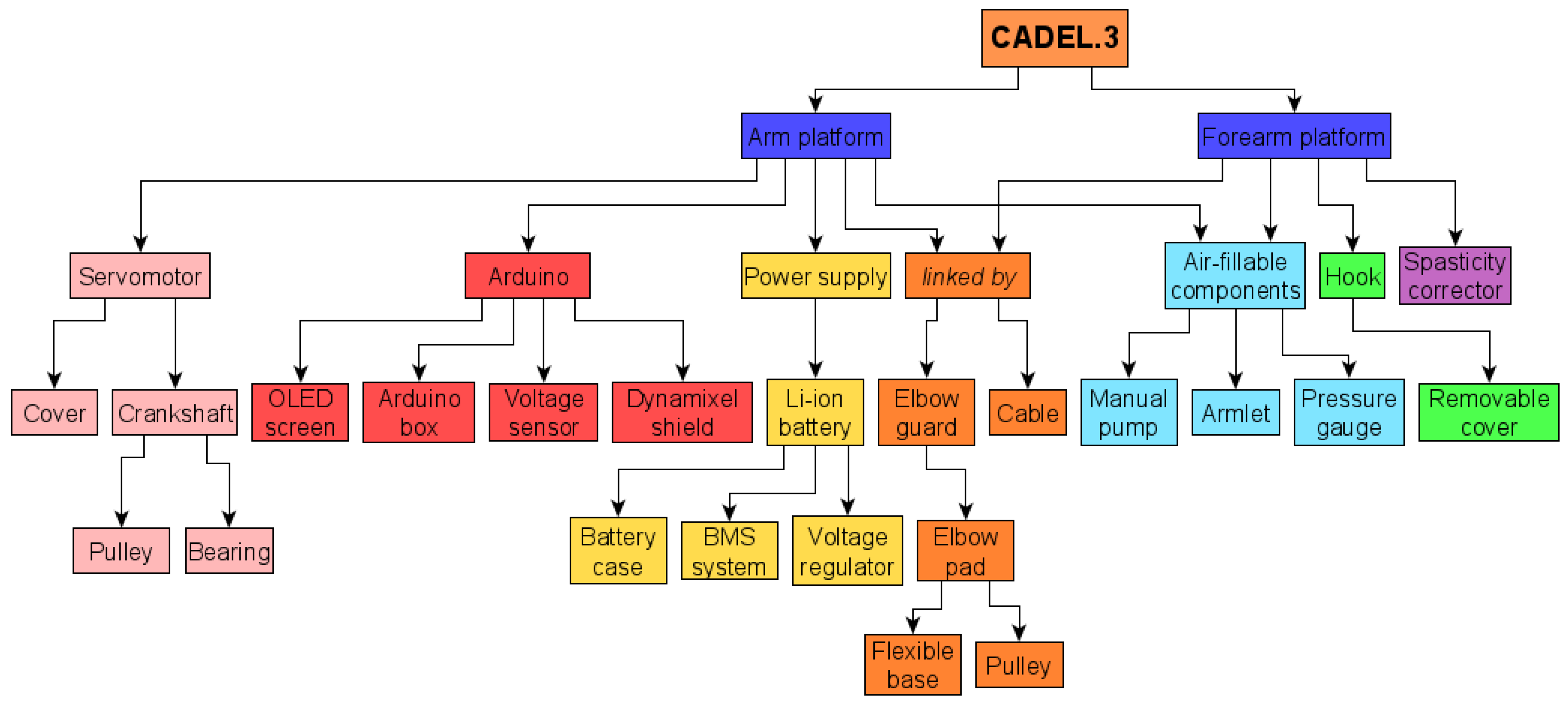
To better highlight all components’ locations inside the prototype, a block diagram is reported in
Figure 9, where the connections between the components are clearly indicated.
Thanks to this block diagram, it is also possible to carry out a cost analysis. Most of the components were selected as available as commercial products in Italy, with a total cost of €330. The remaining components, built by using a 3D printer, have a cost impact that depends on the different variables that can be considered in the evaluation. Considering only material cost, the latter is strictly related to the weight of all 3D components that have been printed with the Fused Deposition Modeling (FDM) technology. All the components weigh 450 g for a material cost of €30. The total cost of the reported prototype is equal to €360, as from the experience at the Laboratory of Robotics of the University of Padova.
Four Dynamixel XL430-W250 servomotors [
36] have been installed on the arm platform. In the proposed solution, only the motors which move cables
and
are controlled and used to operate the motion assistance. To control the motors, an Arduino UNO WiFi Rev.2 board is connected to a tension sensor and an OLED i2c display is implemented for an operator’s interaction. The control law for the motor actions is a traditional trapezoidal speed control law.
The Dynamixel XL430-W250 DC motor proved to be adequate for the execution of the required movement. In fact, its stall torque is Nm, which is significantly larger than the maximum value that is required by the motors during the exercise. Therefore, even more compact motors could be used. At the same time, the reduced power values do not require the use of high-performance and long-lasting batteries, and once again with the advantage of a reduction in weight, size, and cost of the prototype for a completely economic and portable version.
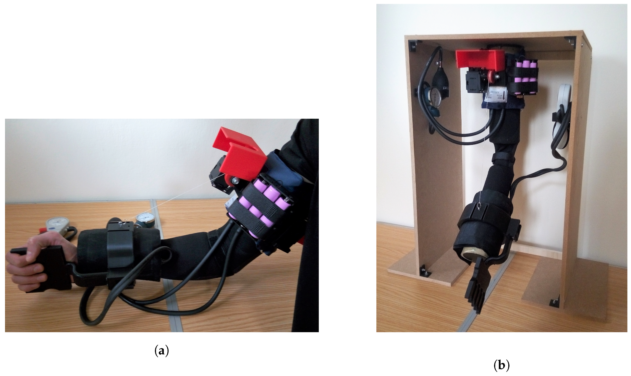
CADEL.3 has been worn for lab testing by healthy humans as in
Figure 10a and no issues have been addressed with regard to wearability. To test the effectiveness of the solution, a test bench has been built as in
Figure 10b. The testbed is made up of a wooden structure that holds the prototype, a circular part that is fixed with respect to the structure (simulating the arm), and another circular part that is connected to the previous one by a rotative joint (simulating the forearm).
The prototype has been tested both in flexion and extension within a range of motion of
(within its workspace of
described in
Section 2), and significant results are reported in
Figure 11 and
Figure 12.
An experimental analysis for a rehabilitation therapy was carried out with the prototype, with five flexion–extension cycles of the robotic arm. Each cycle took a total of s. For each movement, the parameters related to position, rotation speed, torque, and mechanical power were evaluated thanks to the sensors inside the servomotors. To simulate the resistant motion acting in the patient’s elbow, a resistant load was also varied at each test, depending on the motion: namely, for the flexion motion, a weighted wrist strap of 15 N was applied on the forearm, and, for the extension motion, an elastic band, with a middle value of 10 N during the elongation, wrapped the bench wrist.
The range of angular velocity given to the device depends on the speed of the two DC motors. As shown in
Figure 7, the anterior cable variation is larger than the posterior one, so the anterior servomotor must be faster than the posterior one. For this reason, since the upper speed limit is imposed by the anterior motor and it is equal to 57 rpm, the lower speed limit is imposed by the posterior motor and is equal to 1 rpm.
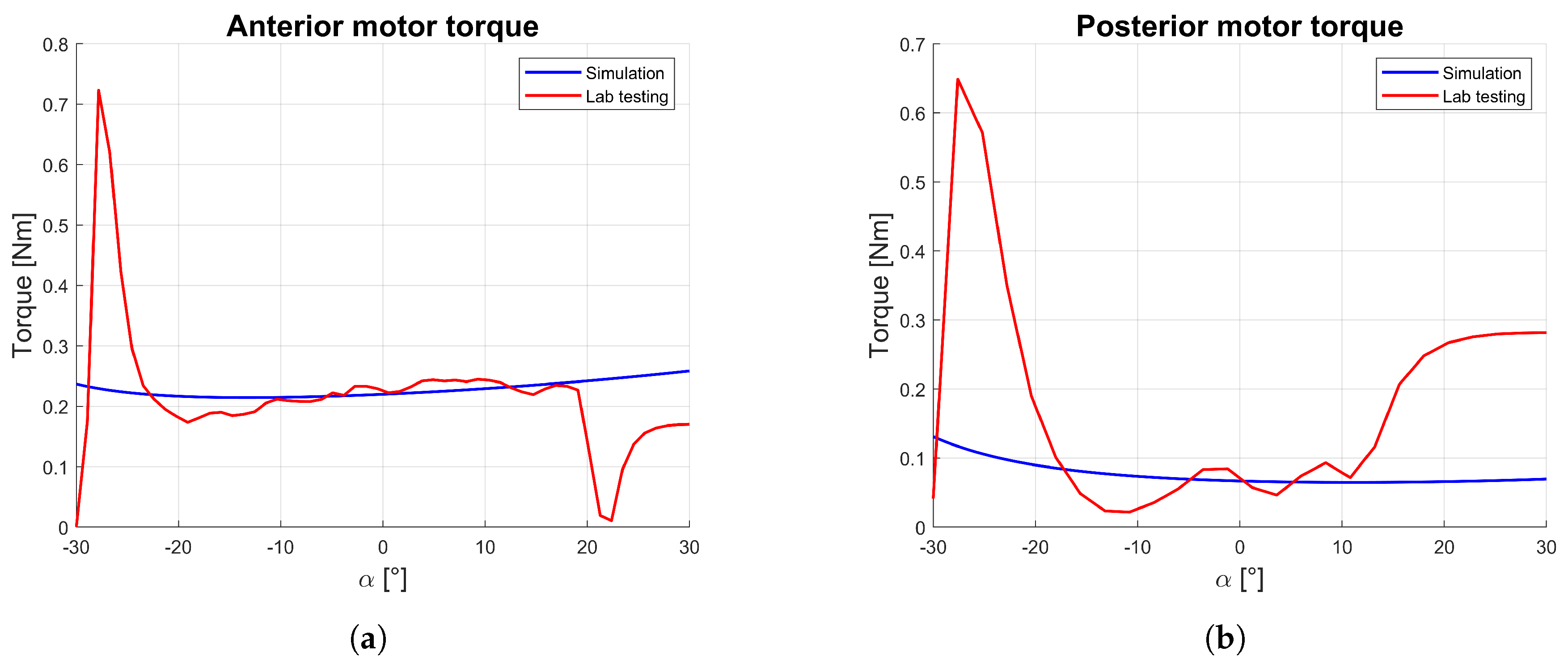
The comparison between the simulation and the experimental results of torque (
Figure 11) indicates as the average value during elbow flexion values
Nm, while the elbow extension required less torque as equal to
Nm. In both situations, the experimental middle value is close to the simulated one, with a near-parabolic trend with a peak at the beginning and end of motion.
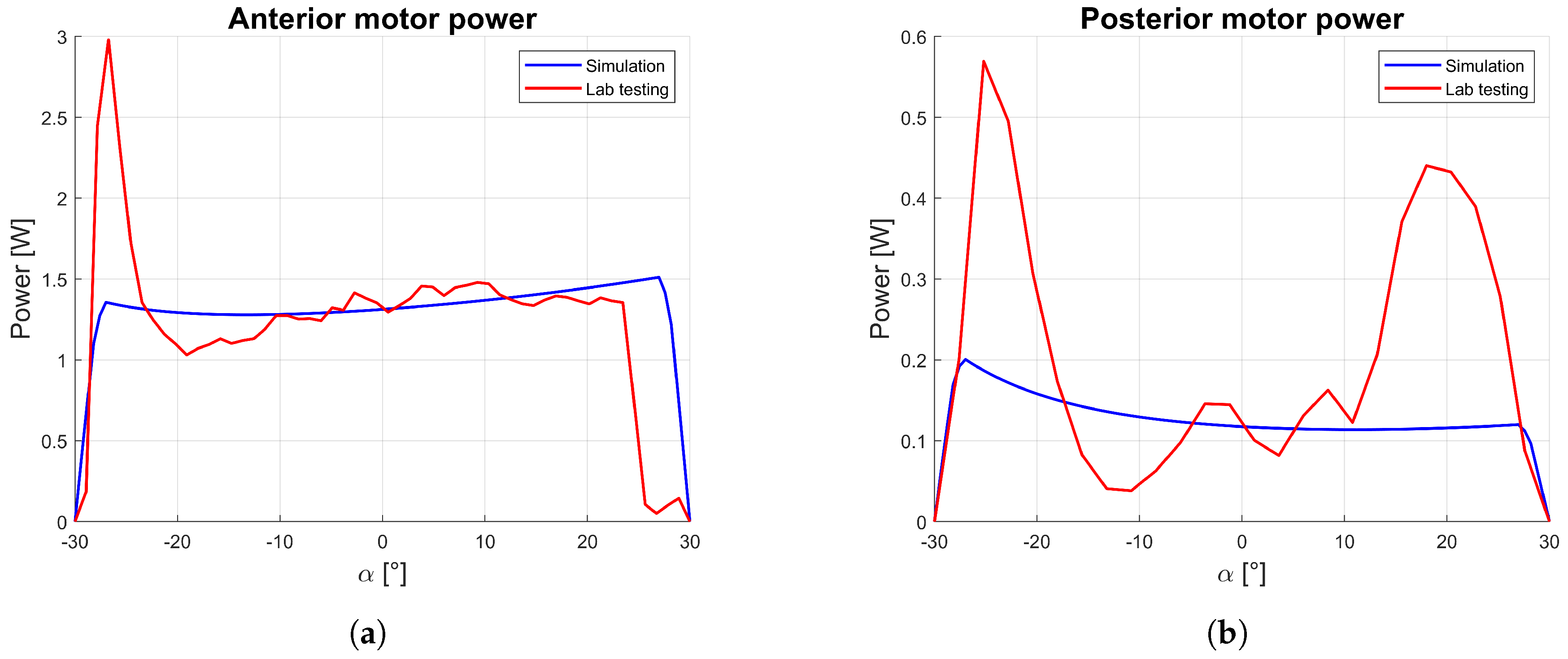
This consideration is similar for mechanical motor power as reported in
Figure 12, which is indirectly estimated by using Equation (
14). In particular, the analytical angular velocity is calculated by computing a symmetrical trapezoidal velocity profile with a specific actuation time and mean velocity. After measuring the average supply current and voltage, the electrical power consumption is equal to
W, and the average battery life is about 30 h (which correspond to approximately 18,000 cycles), demonstrating the suitability of the device for prolonged domestic use.
At the beginning and at the end of movement, there are large differences between results of simulations and tests. This is due to the different origin of the results: the simulation results have been estimated with a quasi-static analysis, while the laboratory tests have been detected during a dynamic motion. Therefore, the first approach does not consider the peaks of torque at the movements’ extremities that motors have to impose to start and finish the motion during the acceleration phases. In particular, at the beginning of both flexion and extension motions, the motor has to accelerate to reach the maximum speed (thus requiring a high torque); at the end of the motion, torque is reduced for the flexion motion since the weight of the forearm helps the deceleration, whilst, during the extension motion, the weight of the forearm is countering the deceleration. Anyway, this difference is not relevant for the test validation as per the aim to verify the correct behavior within the central part of the movement.
From the results, it is clear how the simulation model is coherent with the experimental results. CADEL.3 is shown to be a lightweight and compact device which is suitable for portability, and its operation is characterized by limited power consumption, so that CADEL.3 can be used for a long period of time without the need for recharging. The torques applied by the motors during the movements are limited, so that even more compact motors could be used.
6. Conclusions
Improvements in CADEL.3 prototype have faced all the issues that were raised with previous versions of CADEL design. By reducing the overall dimensions and by halving the total weight of the device, CADEL.3 proves its practical usage in home user-oriented applications with comfort and portability features. CADEL.3 design is based on new design solutions, such as the usage of lightweight platforms, air-inflatable components, elbow guards to improve wearability, and a new cable passage at the elbow. A pulley has been placed on the elbow and, as a result, a constant torque is applied by the rear cable to the elbow with low friction between cables and elbow guard, giving important benefits in terms of patient comfort and power consumption. In addition, other advantages have been achieved for the patient comfort and safety by using the air-inflatable components, the spasticity hand corrector tool, and the protective boxes from the moving parts.
In future developments, it can be planned to improve also the pronation–supination motion assistance, activating the other two motors in the present version to compensate potential lateral movements of the forearm. In this way, it will be possible to carry out experimental tests directly on patients who need elbow rehabilitation. For this reason, the use of additional sensors such as EMG, blood pressure, and body temperature sensor is planned for a fully medical device.
7. Patents
The CADEL device has been patented [
13] or has a patent pending [
32].


